Simultaneous Estimation of Rebar Diameter and Cover Thickness by a GPR-EMI Dual Sensor


Abstract
1. Introduction
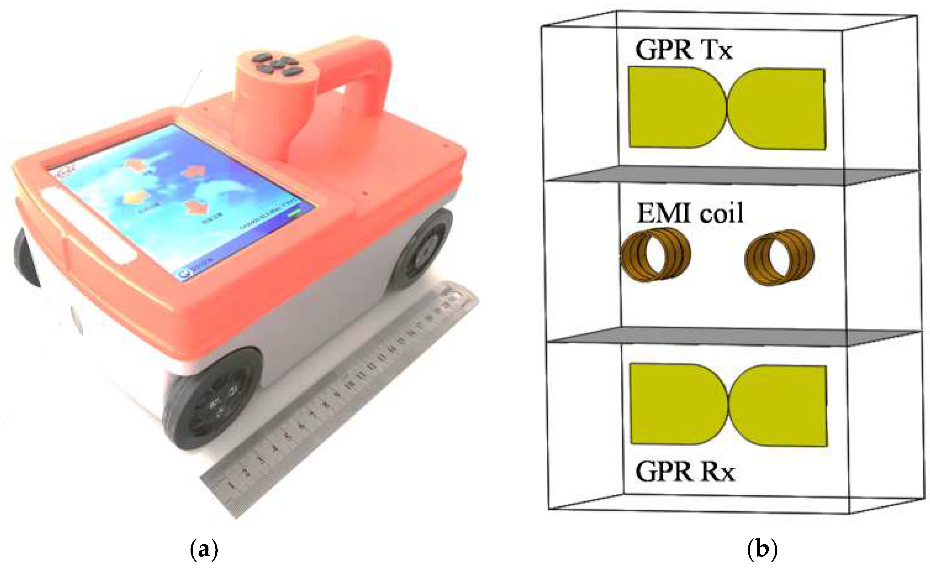
2. GPR-EMI System
2.1. System Description
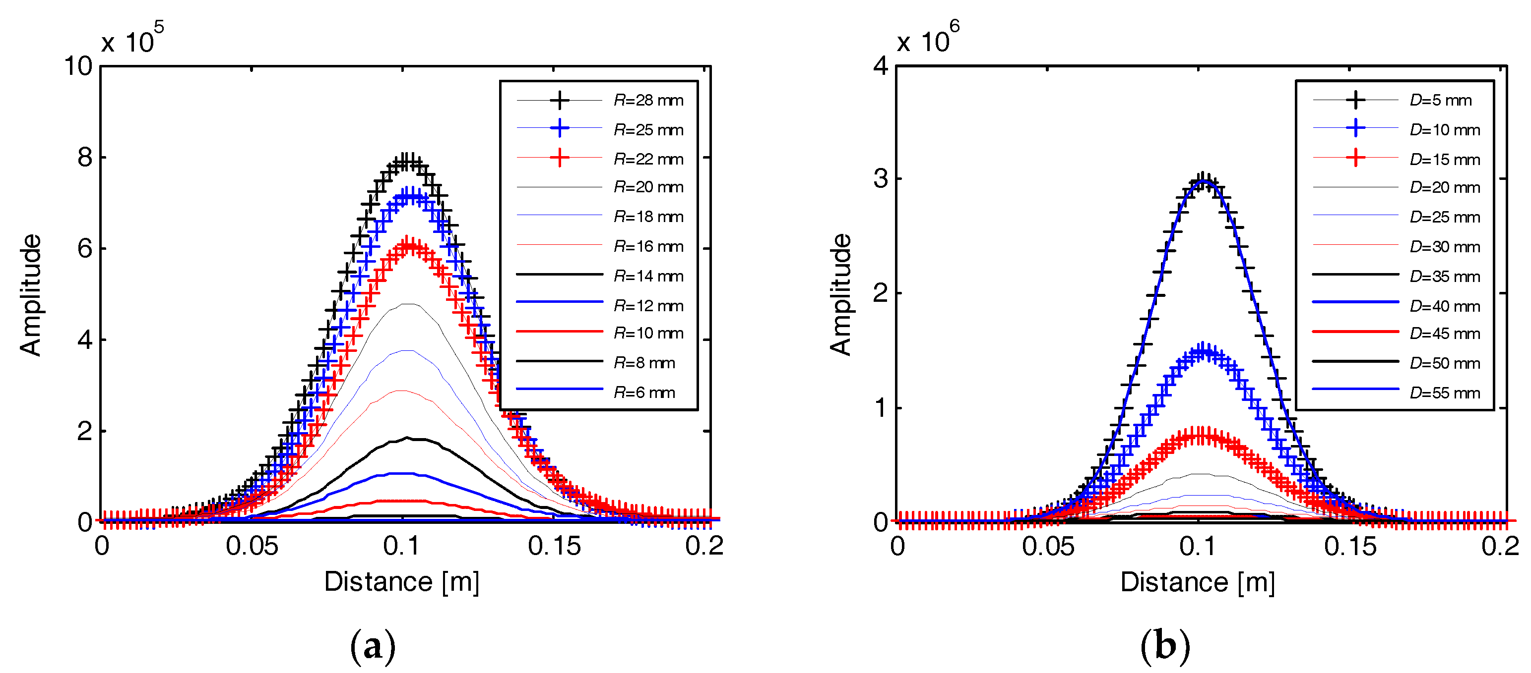
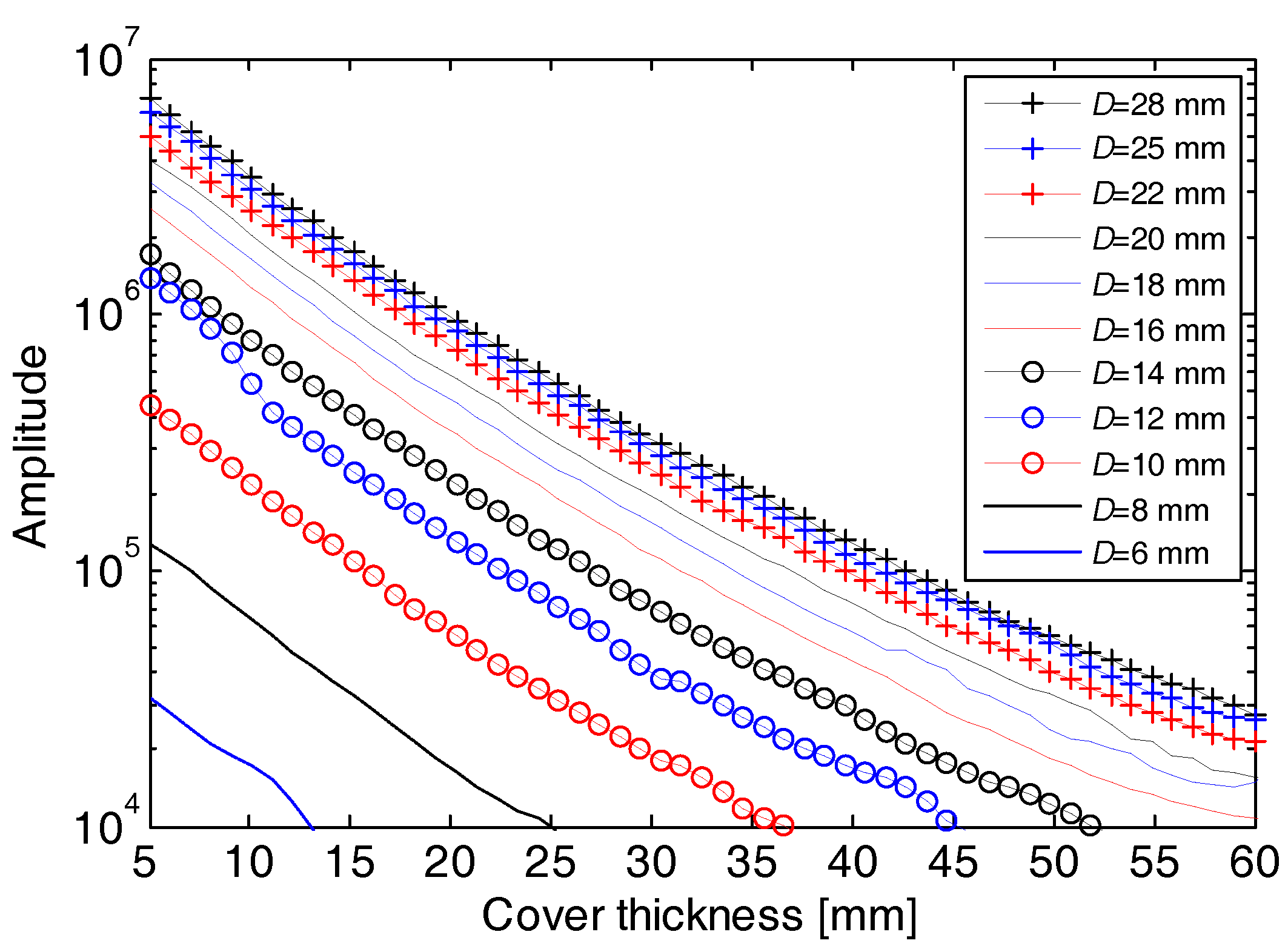
2.2. EMI Calibration
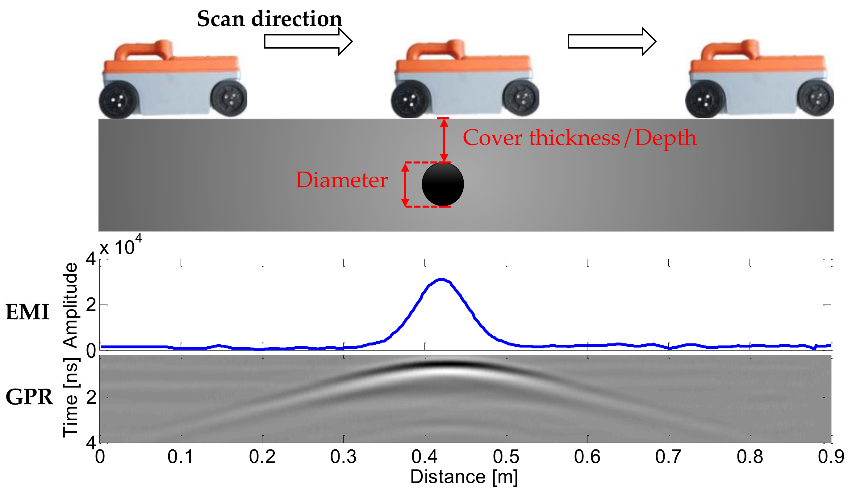
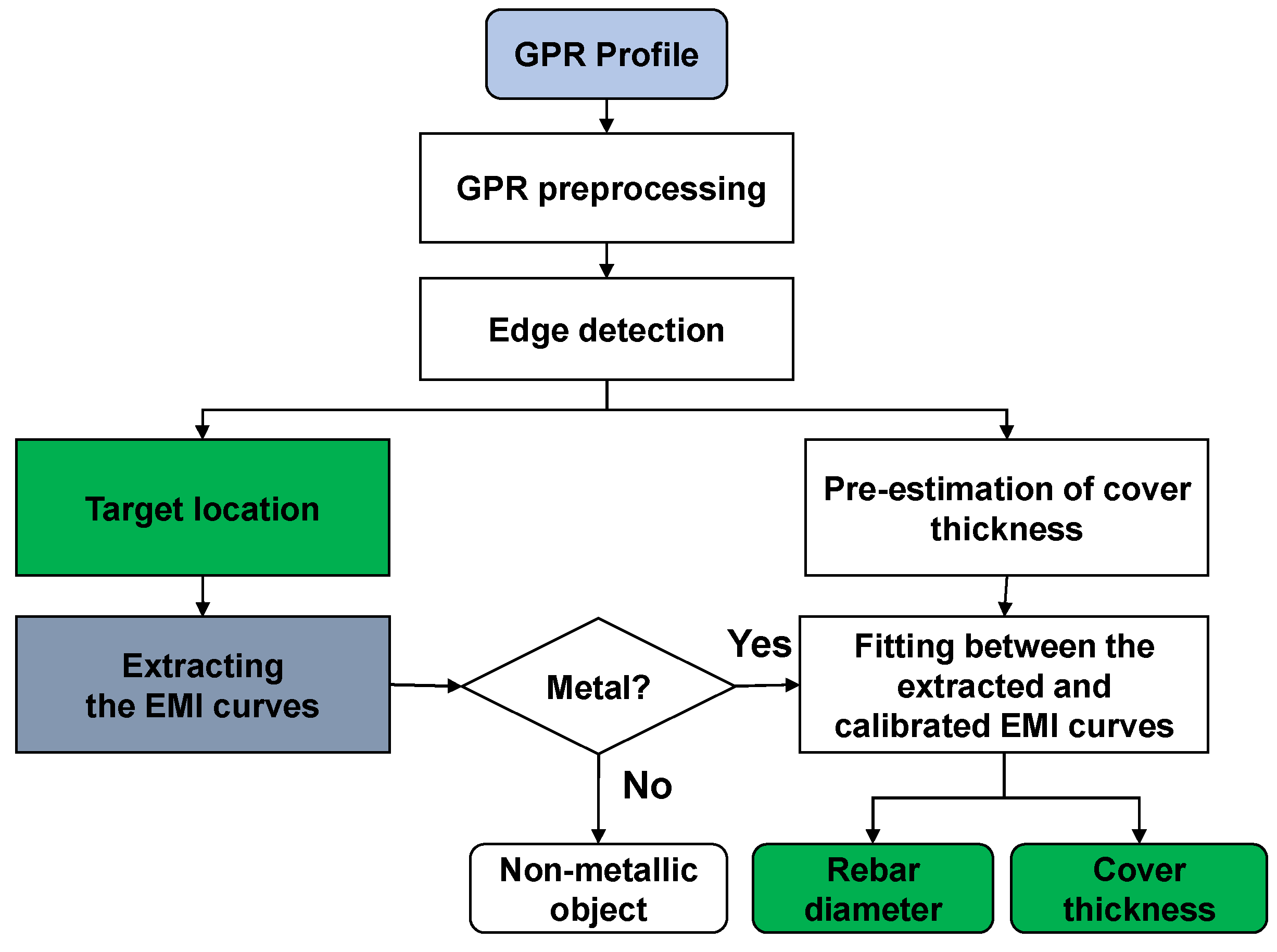
3. Data Processing
- (a)
- The GPR data is preprocessed to increase the signal to noise ratio. A sequence of standard GPR processing techniques are implemented, including DC removal, zero-time correction, band-pass filtering, amplitude scaling, median filtering, and background removal [42].
- (b)
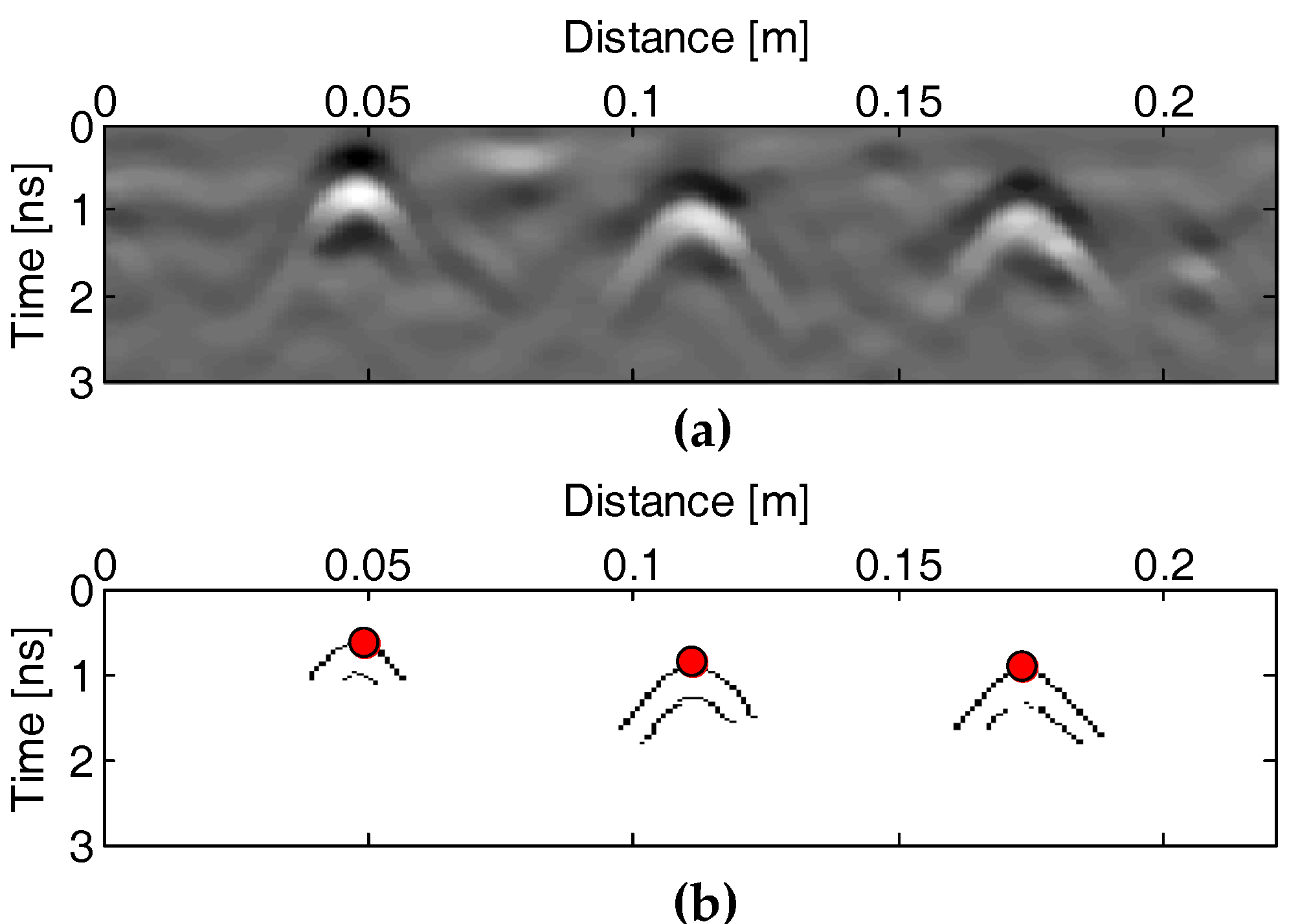
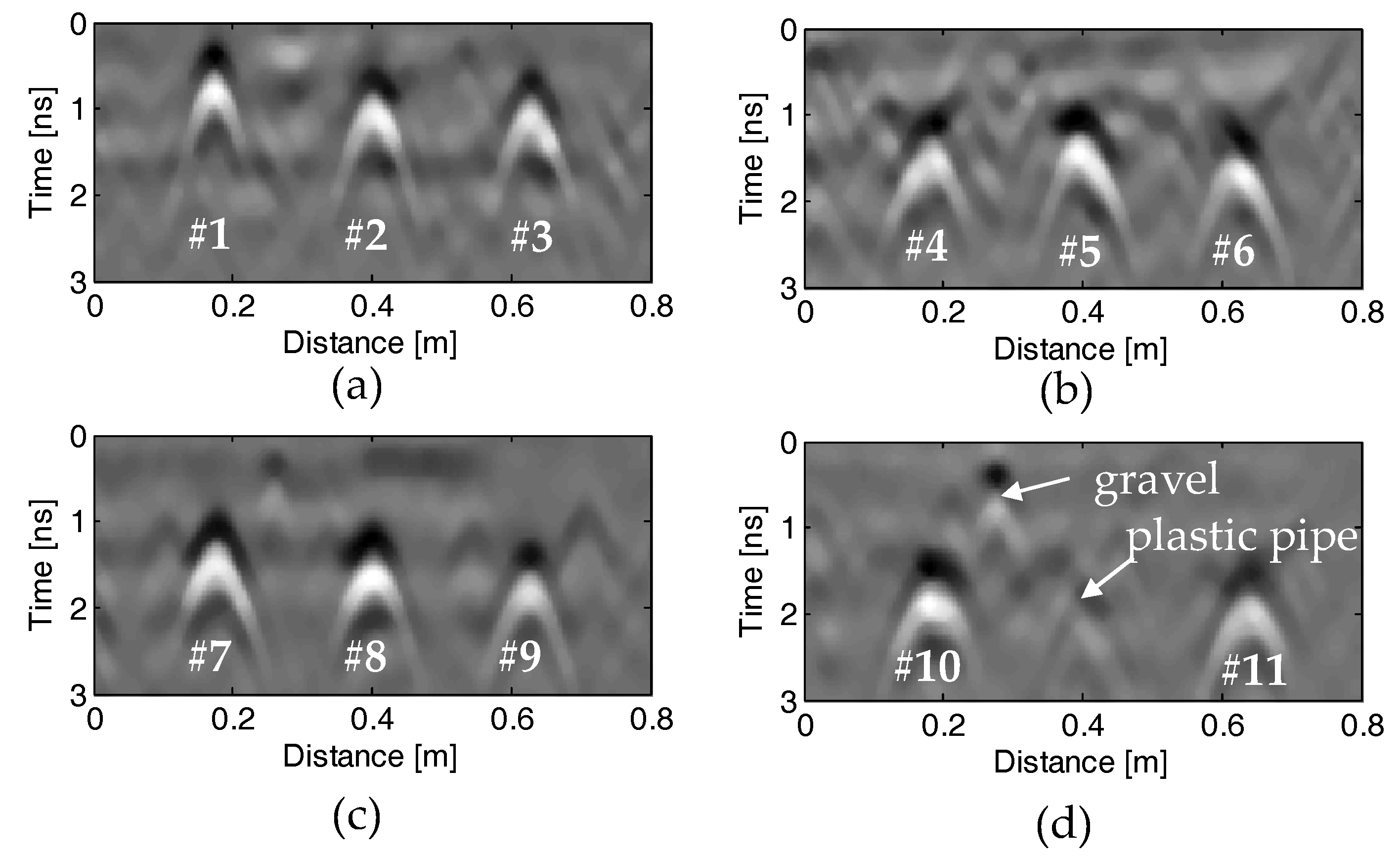
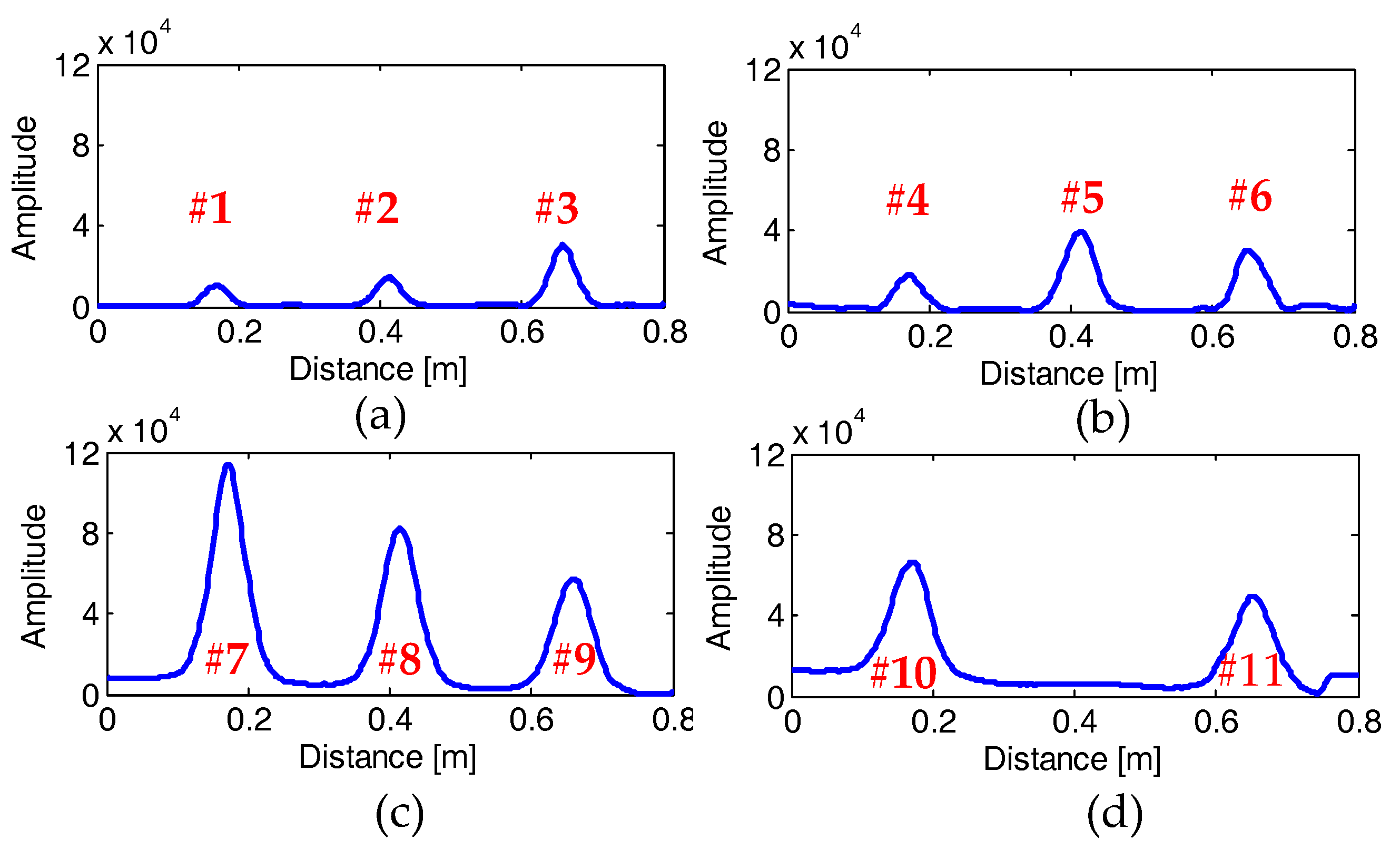
- The hyperbolae from the buried rebars in the GPR profiles are extracted by an edge detection algorithm after pre-processing, and their apex coordinates are picked up for locating the rebar and roughly estimating the cover thickness, as shown in Figure 7. The Sobel operator is used for the edge detection [43]. Figure 7a,b respectively show the preprocessed GPR profile and the binary image after the edge detection. It shows that the Sobel operator is effective for the rebar hyperbola extraction in the GPR profile even if the signal to clutter ratio is high.
- (c)
- Localization of the buried rebar and extraction of the effective EMI curve. From the horizontal coordinate of the detected hyperbolic apexes, the horizontal location of buried rebar can be accurately determined, which is further used to extract the effective EMI curves from the embedded rebar. The effective EMI curve centers on the rebar location with the span defined as twice of the FWHH, and it contains the majority of the useful information in the EMI response while stays away from the noise level. The EMI amplitude, with the location corresponding to the hyperbolic apex of the GPR profile, is used to judge whether the GPR hyperbola is reflected by a rebar or a plastic pipe. If the EMI amplitude is close to the noise level, the reflective object is judged as non-metallic; otherwise, it is judged as a metallic rebar.
- (d)
- Pre-estimation of the cover thickness. Knowing the time coordinate (t) of the hyperbolic apex, the two-way travel time of EM waves propagating from the air-concrete interface to the embedded rebar is used to roughly estimate the cover thickness by:where D is the cover thickness (m), v is the EM wave velocity in the concrete (m/ns), and t is the two-way travel time (ns). The velocity is calculated by:where c is the EM wave velocity in free space, i.e., 0.3 m/ns, and εr is the relative permittivity of the concrete. Taking the heterogeneity of the concrete compositions and the intrusive moisture into account, we assign εr ranging from 4 to 10 [44,45]. The permittivity is utilized to estimate the possible range of rebar cover thickness, which is used as a constraint condition for the accurate estimation of the rebar diameter and cover thickness in the following step.
- (e)
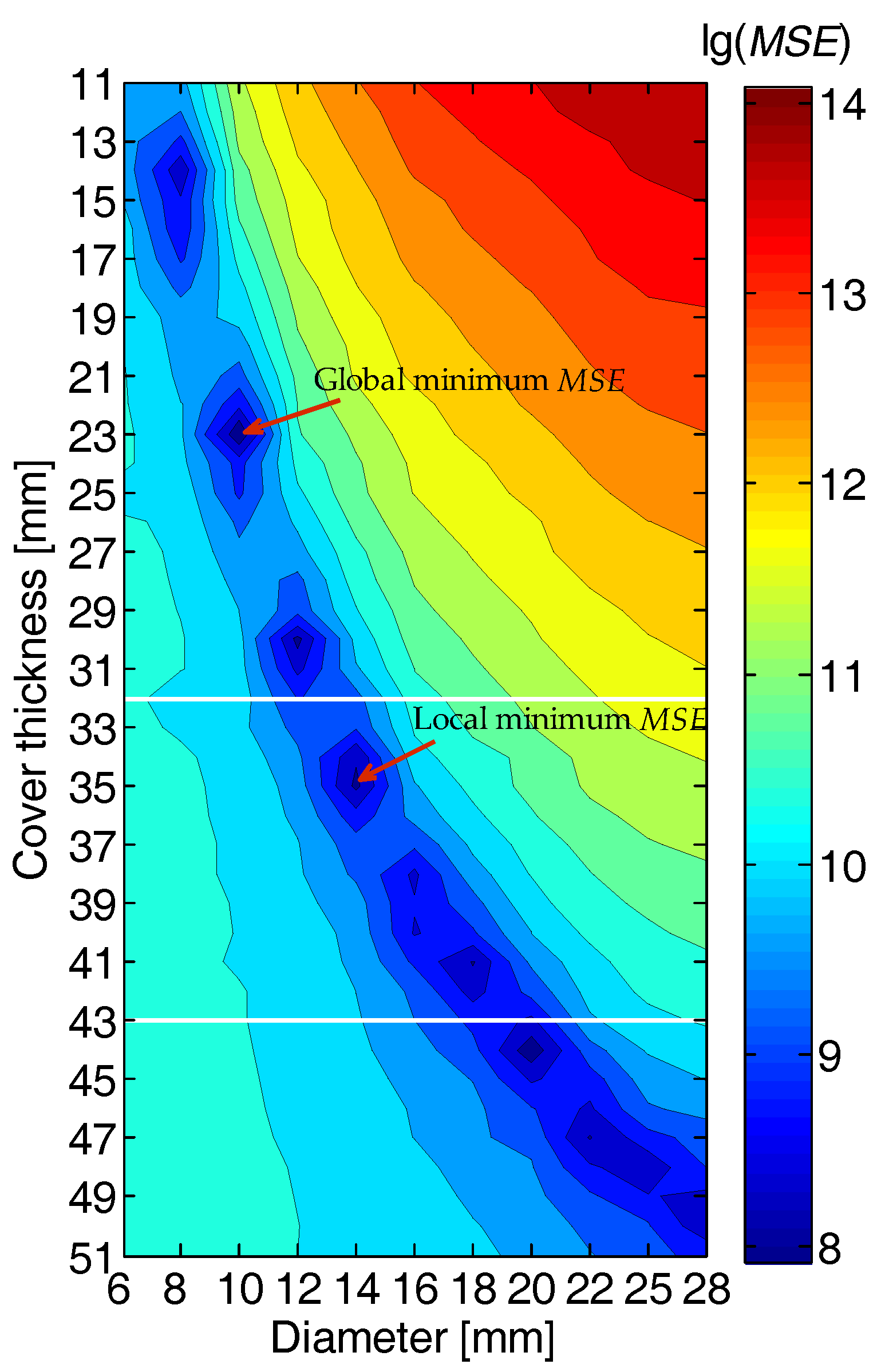
- Determination of the rebar diameter and cover thickness. Through calculating the mean square errors between the EMI data extracted from the field measurement and those calibrated in the laboratory in advance (as stated in the previous section), the rebar diameter and cover thickness are simultaneously estimated through searching the local minimum mean square error under the constraint of the GPR-estimated cover thickness. The error function is expressed by:where f(x) is the in-situ measured EMI curve, is the calibrated EMI curves, i and j are respectively the serial numbers standing for various rebar diameter and cover thickness in the calibration experiment, x is the horizontal coordinate of the EMI curve, l is the intercept length of the extracted effective EMI curve, which is twice of the FWHH as stated above, and MSE is the mean square error. The search of the local minimum MSE is implemented under the constrained scope of the cover thicknesses that are estimated by GPR data in the previous step. This constraint condition avoids multiple solutions of rebar diameter and cover thickness, and thus can improve the estimation accuracy.
4. Laboratory Experiments
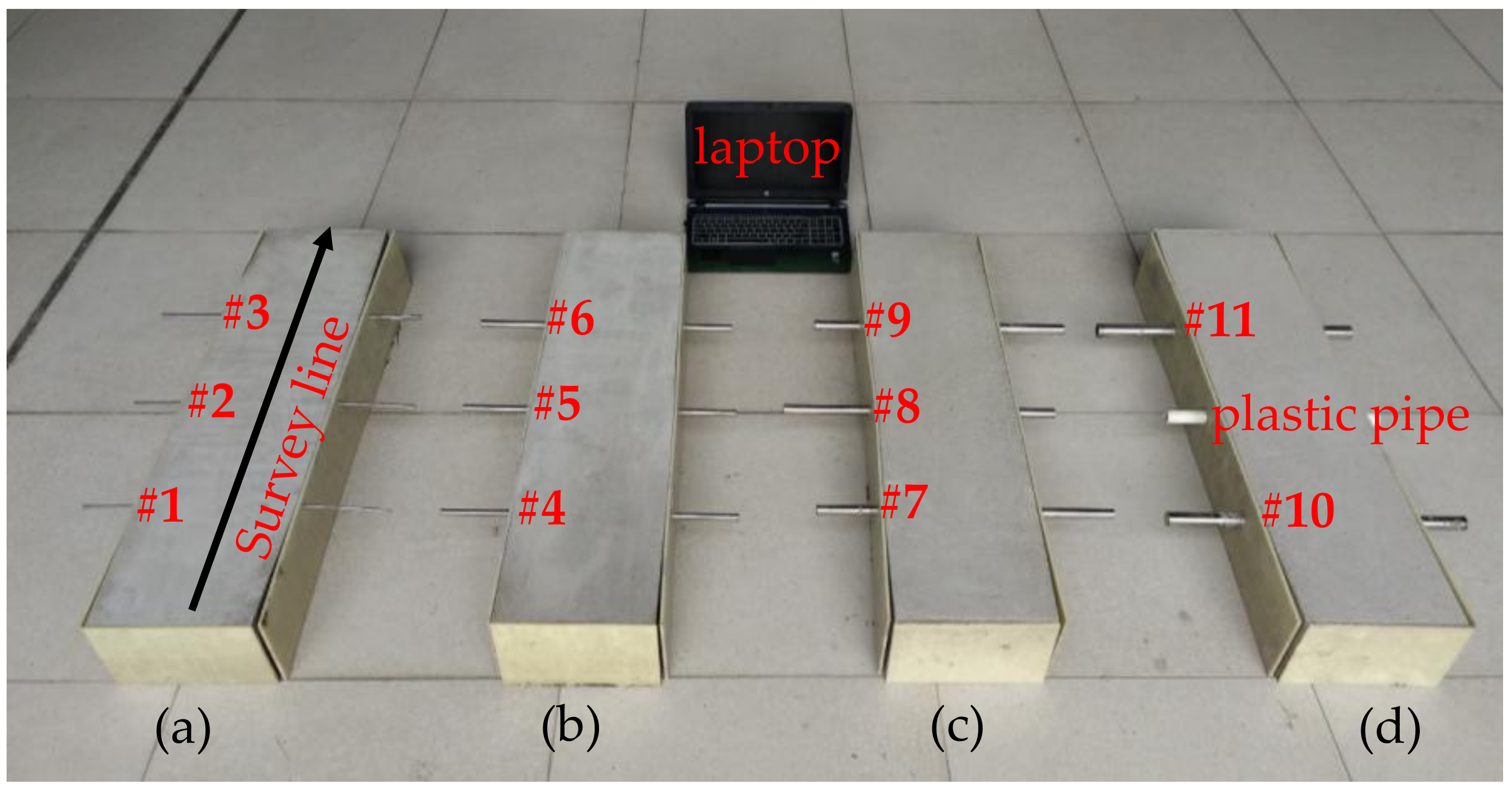
4.1. Experimental Setup
4.2. Results
5. Field Test
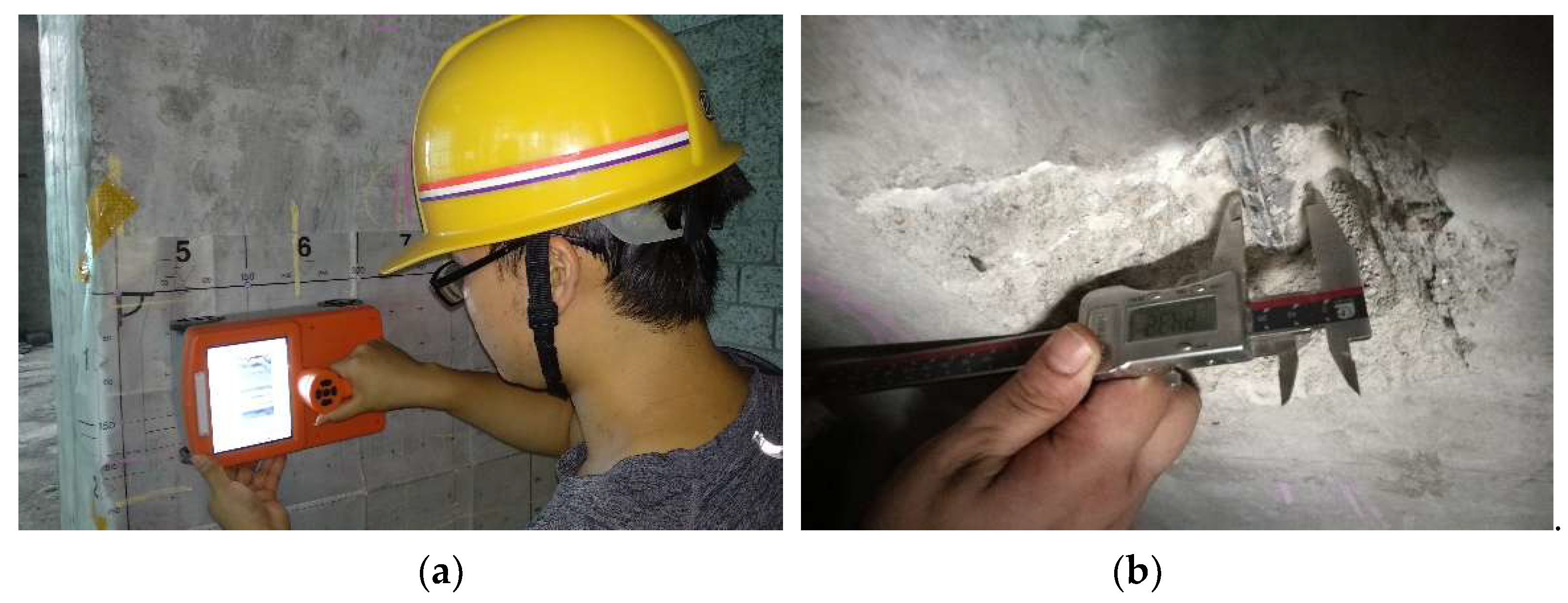
5.1. Site Description
5.2. Results
6. Conclusions
Author Contributions
Funding
Acknowledgments
Conflicts of Interest
References
- McCann, D.M.; Forde, M.C. Review of NDT methods in the assessment of concrete and masonry structures. NDT E Int. 2001, 34, 71–84. [Google Scholar] [CrossRef]
- Utsi, V.; Utsi, E. Measurement of reinforcement bar depths and diameters in concrete. In Proceedings of the Tenth International Conference on Grounds Penetrating Radar, Delft, The Netherlands, 21–24 June 2004; pp. 659–662. [Google Scholar]
- Rens, K.L.; Wipf, T.J.; Klaiber, F.W. Review of Nondestructive Evaluation Techniques of Civil Infrastructure. J. Perform. Constr. Facil. 1997, 11, 152–160. [Google Scholar] [CrossRef]
- Gaydecki, P.A.; Burdekin, F.M. An inductive scanning system for two-dimensional imaging of reinforcing components in concrete structures. Meas. Sci. Technol. 1994, 5, 1272–1280. [Google Scholar] [CrossRef]
- Gaydecki, P.; Silva, I.; Fernandes, B.T.; Yu, Z.Z. A portable inductive scanning system for imaging steel-reinforcing bars embedded within concrete. Sens. Actuators A Phys. 2000, 84, 25–32. [Google Scholar] [CrossRef]
- Allidred, J.; Chua, J.; Chamberlain, D. Determination of reinforcing bar diameter and cover by analysing traverse profiles from a cover meter. In Proceedings of the International Symposium Non-Destructive Testing in Civil Engineering, Berlin, Germany, 26–28 Sepetember 1995; pp. 721–728. [Google Scholar]
- Fernandes, B.T.; Silva, I.; Gaydecki, P.A. Vector extraction from digital images of steel bars produced by an inductive scanning system using a differential gradient method combined with a modified Hough transform. NDT E Int. 2000, 33, 69–75. [Google Scholar] [CrossRef]
- Quek, S.; Gaydecki, P.; Zaid, M.A.M.; Miller, G.; Fernandes, B. Three-dimensional image rendering of steel reinforcing bars using curvilinear models applied to orthogonal line scans taken by an inductive sensor. NDT E Int. 2003, 36, 7–18. [Google Scholar] [CrossRef]
- Sivasubramanian, K.; Jaya, K.P.; Neelemegam, M. Covermeter for identifying cover depth and rebar diameter in high strength concrete. Int. J. Civ. Struct. Eng. 2013, 3, 557–563. [Google Scholar]
- Alldred, J. Improvement to the orthogonal method for determining reinforcing bar diameter using a cover meter. In Proceedings of the Sixth International Conference on Structural Faults and Repair, London, UK, 3–5 July 1995; pp. 11–15. [Google Scholar]
- Zaid, M.; Gaydecki, P.; Quek, S.; Miller, G.; Fernandes, B. Extracting dimensional information from steel reinforcing bars in concrete using neural networks trained on data from an inductive sensor. NDT E Int. 2004, 37, 551–558. [Google Scholar] [CrossRef]
- Algernon, D.; Hiltunen, D.R.; Ferraro, C.C.; Ishee, C. Rebar detection with cover meter and ultrasonic pulse echo combined with automated scanning system. J. Transp. Res. Board. 2011, 2251, 123–131. [Google Scholar] [CrossRef]
- Prego, F.J.; Solla, M.; Puente, I.; Arias, P. Efficient GPR data acquisition to detect underground pipes. NDT E Int. 2017, 91, 22–31. [Google Scholar] [CrossRef]
- Liu, H.; Deng, Z.; Han, F.; Xia, Y.; Liu, Q.H.; Sato, M. Time-frequency analysis of air-coupled GPR data for identification of delamination between pavement layers. Constr. Build. Mater. 2017, 154, 1207–1215. [Google Scholar] [CrossRef]
- Liu, H.; Sato, M. In situ measurement of pavement thickness and dielectric permittivity by GPR using an antenna array. NDT E Int. 2014, 64, 65–71. [Google Scholar] [CrossRef]
- Liu, H.; Takahashi, K.; Sato, M. Measurement of dielectric permittivity and thickness of snow and ice on a brackish lagoon using GPR. IEEE J. Sel. Top. Appl. Earth Obs. Remote Sens. 2014, 7, 820–827. [Google Scholar] [CrossRef]
- Zhou, F.; Miorali, M.; Slob, E.; Hu, X. Reservoir monitoring using borehole radars to improve oil recovery: Suggestions from 3D electromagnetic and fluid modeling. Goephyiscs 2018, 83, WB19–WB32. [Google Scholar] [CrossRef]
- Ciarletti, V.; Corbel, C.; Plettemeier, D.; Cais, P.; Clifford, S.M.; Hamran, S.E. WISDOM GPR designed for shallow and high-resolution sounding of the martian subsurface. Proc. IEEE 2011, 99, 824–836. [Google Scholar] [CrossRef]
- He, X.; Zhu, Z.; Liu, Q.; Lu, G. Review of GPR rebar detection. In Proceedings of the Progress in Electromagnetics Research Symposium, Beijing, China, 23–27 March 2009; pp. 804–813. [Google Scholar]
- Chang, C.W.; Lin, C.H.; Lien, H.S. Measurement radius of reinforcing steel bar in concrete using digital image GPR. Constr. Build. Mater. 2009, 23, 1057–1063. [Google Scholar] [CrossRef]
- Zanzi, L.; Arosio, D. Sensitivity and accuracy in rebar diameter measurements from dual-polarized GPR data. Constr. Build. Mater. 2013, 48, 1293–1301. [Google Scholar] [CrossRef]
- Wiwatrojanagul, P.; Sahamitmongkol, R.; Tangtermsirikul, S.; Khamsemanan, N. A new method to determine locations of rebars and estimate cover thickness of RC structures using GPR data. Constr. Build. Mater. 2017, 140, 257–273. [Google Scholar] [CrossRef]
- Kalogeropoulos, A.; van der Kruk, J.; Hugenschmidt, J.; Busch, S.; Merz, K. Chlorides and moisture assessment in concrete by GPR full waveform inversion. Near Surf. Geophys. 2011, 9, 277–285. [Google Scholar] [CrossRef]
- Chen, W.; Shen, P.; Shui, Z. Determination of water content in fresh concrete mix based on relative dielectric constant measurement. Constr. Build. Mater. 2012, 34, 306–312. [Google Scholar] [CrossRef]
- Hong, S.; Lai, W.L.; Helmerich, R. Experimental monitoring of chloride-induced reinforcement corrosion and chloride contamination in concrete with ground-penetrating radar. Struct. Infrastruct. Eng. 2015, 11, 15–26. [Google Scholar] [CrossRef]
- Hong, S.; Wiggenhauser, H.; Helmerich, R.; Dong, B.; Dong, P.; Xing, F. Long-term monitoring of reinforcement corrosion in concrete using ground penetrating radar. Corros. Sci. 2017, 114, 123–132. [Google Scholar] [CrossRef]
- Gu, P.; Beaudoin, J.J. Dielectric behaviour of hardened cementitious materials. Adv. Cem. Res. 1997, 9, 1–8. [Google Scholar] [CrossRef]
- AL-Qadi, I.L.; Lahouar, S. Measuring layer thicknesses with GPR–Theory to practice. Constr. Build. Mater. 2005, 19, 763–772. [Google Scholar] [CrossRef]
- Shihab, S.; Al-Nuaimy, W. Radius estimation for cylindrical objects detected by ground penetrating radar. Subsurf. Sens. Technol. Appl. 2005, 6, 151–166. [Google Scholar] [CrossRef]
- Ristic, A.V.; Petrovacki, D.; Govedarica, M. A new method to simultaneously estimate the radius of a cylindrical object and the wave propagation velocity from GPR data. Comput. Geosci. 2009, 35, 1620–1630. [Google Scholar] [CrossRef]
- Brunzell, H. Detection of shallowly buried objects using impulse radar. IEEE Trans. Geosci. Remote Sens. 1999, 37, 875–886. [Google Scholar] [CrossRef]
- Mechbal, Z.; Khamlichi, A. Determination of concrete rebars characteristics by enhanced post-processing of GPR scan raw data. NDT E Int. 2017, 89, 30–39. [Google Scholar] [CrossRef]
- Windsor, C.G.; Capineri, L.; Falorni, P. The estimation of buried pipe diameters by generalized Hough transform of radar data. In Proceedings of the Progress in Electromagnetic Research Symposium, Hangzhou, China, 22–26 August 2005; pp. 345–349. [Google Scholar]
- Liu, H.; Xing, B.; Zhu, J.; Zhou, B.; Wang, F.; Xie, X.; Liu, Q.H. Quantitative stability analysis of ground penetrating radar systems. IEEE Geosci. Remote Sens. Lett. 2018, 15, 522–526. [Google Scholar] [CrossRef]
- Feng, X.; Sato, M.; Liu, C. Subsurface imaging using a handheld GPR MD system. IEEE Geosci. Remote Sens. Lett. 2012, 9, 659–662. [Google Scholar] [CrossRef]
- Van Meirvenne, M.; Van De Vijver, E.; Vandenhaute, L.; Seuntjens, P. Investigating soil pollution with the aid of EMI and GPR measurements. In Proceedings of the 15th International Conference on Ground Penetrating Radar, Brussels, Belgium, 30 June–4 July 2014; pp. 1006–1009. [Google Scholar]
- Yoder, R.E.; Freeland, R.S.; Ammons, J.T.; Leonard, L.L. Mapping agricultural fields with GPR and EMI to identify offsite movement of agrochemicals. J. Appl. Geophys. 2001, 47, 251–259. [Google Scholar] [CrossRef]
- Inman, D.J.; Freeland, R.S.; Ammons, J.T.; Yoder, R.E. Soil investigations using electromagnetic induction and ground-penetrating radar in southwest Tennessee. Soil Sci. Soc. Am. J. 2002, 66, 206–211. [Google Scholar] [CrossRef]
- Saey, T.; Delefortrie, S.; Verdonck, L.; De Smedt, P.; Van Meirvenne, M. Integrating EMI and GPR data to enhance the three-dimensional reconstruction of a circular ditch system. J. Appl. Geophys. 2014, 101, 42–50. [Google Scholar] [CrossRef]
- Gao, Y.; Ye, S.; Zhang, X.; Fang, G. Novel detection system based on EMI and UWB radar. Electron. Meas. Technol. 2015, 38, 128–134. (In Chinese) [Google Scholar]
- China National Standards GB-T 1499.2-2018. Steel for the Reinforcement of Concrete—Part 2: Hot Rolled Ribbed Bars; China National Standards: Shenzhen, China, 2018. (In Chinese)
- Cassidy, N.J. Ground penetrating radar data processing, modelling and analysis. In Ground Penetrating Radar: Theory and Applications, 1st ed.; Jol, H.M., Ed.; Elsevier Science: Amsterdam, The Netehrlands, 2009; pp. 141–176. ISBN 978-0-444-53348-7. [Google Scholar]
- Ansari, M.D.; Mishra, A.R.; Ansari, F.T. New divergence and entropy measures for intuitionistic fuzzy sets on edge detection. Int. J. Fuzzy Syst. 2018, 20, 474–487. [Google Scholar] [CrossRef]
- Senin, S.F.; Hamid, R. Ground penetrating radar wave attenuation models for estimation of moisture and chloride content in concrete slab. Constr. Build. Mater. 2016, 106, 659–669. [Google Scholar] [CrossRef]
- Cassidy, N.J. Electrical and magnetic properties of rocks, soils and fluids. In Ground Penetrating Radar: Theory and Applications, 1st ed.; Jol, H.M., Ed.; Elsevier Science: Amsterdam, The Netehrlands, 2009; pp. 41–72. ISBN 978-0-444-53348-7. [Google Scholar]
- Comite, D.; Galli, A.; Catapano, I.; Soldovieri, F. The role of the antenna radiation pattern in the performance of a microwave tomographic approach for GPR imaging. IEEE J. Sel. Top. Appl. Earth Obs. Remote Sens. 2017, 10, 4337–4347. [Google Scholar] [CrossRef]
- Pettinelli, E.; Di Matteo, A.; Mattei, E.; Crocco, L.; Soldovieri, F.; Redman, J.D.; Annan, A.P. GPR response from buried pipes: Measurement on field site and tomographic reconstructions. IEEE Trans. Geosci. Remote Sens. 2009, 47, 2639–2645. [Google Scholar] [CrossRef]


| No. | Cover Thickness | Diameter | |||||
|---|---|---|---|---|---|---|---|
| True | GPR Pre-Estimated | Estimated | Error | True | Estimated | Error | |
| #1 | 15 mm | 11–19 mm | 14 mm | 6.7% | 6 mm | 6 mm | 0 |
| #2 | 21 mm | 18–28 mm | 21 mm | 0 | 8 mm | 8 mm | 0 |
| #3 | 25 mm | 20–31 mm | 25 mm | 0 | 10 mm | 10 mm | 0 |
| #4 | 37 mm | 31–42 mm | 36 mm | 2.7% | 12 mm | 12 mm | 0 |
| #5 | 35 mm | 32–43 mm | 35 mm | 0 | 14 mm | 14 mm | 0 |
| #6 | 42 mm | 38–49 mm | 41 mm | 2.4% | 16 mm | 16 mm | 0 |
| #7 | 32 mm | 31–41 mm | 33 mm | 3.1% | 18 mm | 18 mm | 0 |
| #8 | 38 mm | 36–47 mm | 39 mm | 2.6% | 20 mm | 20 mm | 0 |
| #9 | 43 mm | 40–53 mm | 43 mm | 0 | 22 mm | 20 mm | 9.1% |
| #10 | 46 mm | 43–56 mm | 47 mm | 2.2% | 25 mm | 25 mm | 0 |
| #11 | 50 mm | 47–60 mm | 50 mm | 0 | 28 mm | 28 mm | 0 |
| No. | Cover Thickness | Rebar Diameter | ||||
|---|---|---|---|---|---|---|
| Measured | Estimated | Error | Measured | Estimated | Error | |
| ① | 36.8 mm | 35 mm | 4.9% | 24.7 mm | 25 mm | 1.2% |
| ② | 23.4 mm | 24 mm | 2.6% | 27.7 mm | 28 mm | 1.1% |
| ③ | 46.2 mm | 46 mm | 0.4% | 24.3 mm | 25 mm | 2.9% |
| ④ | 46.8 mm | 46 mm | 1.7% | 24.4 mm | 25 mm | 2.5% |
© 2018 by the authors. Licensee MDPI, Basel, Switzerland. This article is an open access article distributed under the terms and conditions of the Creative Commons Attribution (CC BY) license (http://creativecommons.org/licenses/by/4.0/).
Share and Cite
Zhou, F.; Chen, Z.; Liu, H.; Cui, J.; Spencer, B.F.; Fang, G. Simultaneous Estimation of Rebar Diameter and Cover Thickness by a GPR-EMI Dual Sensor. Sensors 2018, 18, 2969. https://doi.org/10.3390/s18092969
Zhou F, Chen Z, Liu H, Cui J, Spencer BF, Fang G. Simultaneous Estimation of Rebar Diameter and Cover Thickness by a GPR-EMI Dual Sensor. Sensors. 2018; 18(9):2969. https://doi.org/10.3390/s18092969
Chicago/Turabian StyleZhou, Feng, Zhongchang Chen, Hai Liu, Jie Cui, Billie F. Spencer, and Guangyou Fang. 2018. "Simultaneous Estimation of Rebar Diameter and Cover Thickness by a GPR-EMI Dual Sensor" Sensors 18, no. 9: 2969. https://doi.org/10.3390/s18092969
APA StyleZhou, F., Chen, Z., Liu, H., Cui, J., Spencer, B. F., & Fang, G. (2018). Simultaneous Estimation of Rebar Diameter and Cover Thickness by a GPR-EMI Dual Sensor. Sensors, 18(9), 2969. https://doi.org/10.3390/s18092969