1. Introduction
With the spread of social networking services, such as Instagram and Twitter, in recent years, the need to take photographs on a daily basis has increased [
1,
2,
3,
4,
5]. Additionally, lifelogging, in which photographs are taken automatically, is attracting attention in the memory rehabilitation field [
6,
7,
8]. We use smartphones and digital cameras when taking photographs. If you want to use your smartphone or camera to take photographs, without missing important moments, you need to be ready to take a picture at any time. In other words, it is necessary to always be equipped with a smartphone or a camera just as you would be if you were a cameraman. Realistically, it is difficult to be ready with your smartphone or camera at any time. If you use eyeglass-type terminals equipped with cameras, such as the SmartEyeglass SED-E1 (Sony Corp., Tokyo, Japan) [
9], you will not have to be always be prepared; however, since the shutter needs to be pressed manually, you will always have to leave your hands available to operate the shutter. Eyeglass-type terminals, such as GLΛSS (X Development LLC., CA, USA) [
10,
11,
12] etc., using voice recognition technology, have functions that enable you to take photographs with just your voice, without using your hands. However, voice technology has a disadvantage because the accuracy of the recognition is influenced by surrounding noise, and only registered languages can be used. Additionally, in locations where silence needs to be maintained, photographs cannot be taken with due consideration of courtesy. Methods other than voice recognition include operating the shutter by blinking, and the development of devices [
13] that can be attached to glasses; however, if you close your eyes, it will be difficult to capture an important scene that you want to preserve while looking at it.
The SenseCam is an effective device for use in lifelogging [
14,
15]. It is a lightweight, non-invasive digital camera, and is used by being hung around one’s neck like a pendant. It uses light, heat, or time as photograph triggers, and automatically takes pictures independently (without the user operating by hand) of the user’s will. The SenseCam, with its wide-angle lens can capture pictures over a wide range. Using this, lifelogging is capable of building autobiographical memories for improving memory, which is useful for memory rehabilitation in the elderly and those with mild forms of Alzheimer’s disease [
6,
7,
8].
The lightweight, non-invasive wearable camera is suited for taking photographs for Instagram, Twitter, and lifelogging. Because there are countries, such as Japan, where taking photographs of people without their permission is punishable by law, it is important, particularly in the case of photographs that will be published on the Net, to ensure that additional people are not photographed. When using wearable cameras for Instagram or Twitter photography, it is important to be able to take pictures when the user wants to take pictures by exercising their free will, and to be able to take pictures close to the scenes the user is looking at (only scenes the user intended). A mechanism by which surrounding people can be aware pictures being taken is also required to prevent non-consensual photography.
To match the landscape seen by your eyes and the captured photographs and videos, it is necessary to attach the camera close to your eyes (i.e., it is necessary to install the camera in your own line of sight). Methods of realizing this include a method of embedding a camera in an eyeglass-type terminal [
9,
10,
11,
12] and a method in which the eyeglass seal is equipped with a camera [
13]. However, those people who are already wearing glasses would need to insert a lens at a degree matching their own eyesight into the camera-embedded glasses, and this would increase the cost of installation. Alternatively, if you are attaching a camera to the glasses that you are currently using, the extent to which the shape of the camera attachment section and the temples of the spectacles match greatly affects the stability of the camera, and thus directly influences the quality of the picture taken.
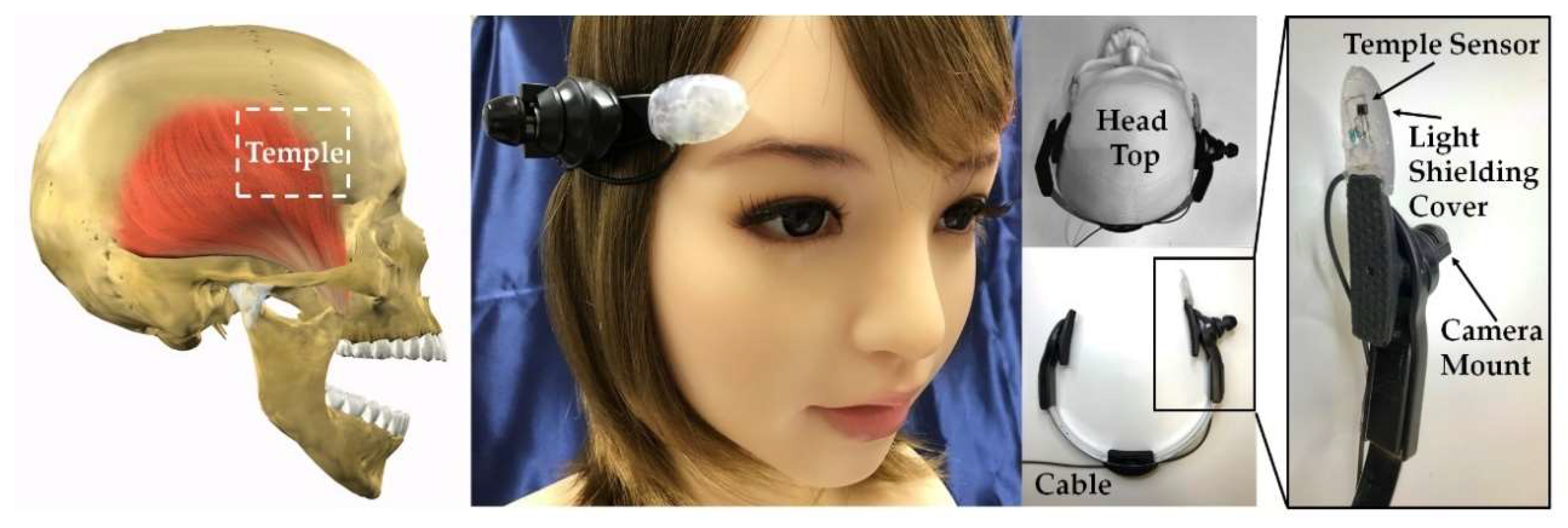
Therefore, we developed a compact, lightweight wearable terminal that can take pictures and video, by the user’s volition, from a position and angle close to the eyeline of the user. This wearable terminal has a mechanism by which it can both take pictures hands-free and it is easy for surrounding people to know that pictures are being taken. We have attached a small camera to the head of the participant and developed a head-mounted camera that can capture photographs and video, hands-free, by simply opening and closing your mouth. Opening and closing the mouth is an action that most people can perform simply, even if they cannot move their arms and legs freely or speak the specific language registered in the device, and the extension and contraction of the temporalis that accompanies the opening and closing of the mouth can be freely done by most people. Activating the shutter “press button” by moving the temporal muscle changes a freely movable part of the body for the button, and this can be linked reliably to the shutter operation. Measuring the opening and closing of the mouth is achieved by attaching a sensor for measuring the movement of the temporalis, which is one of the muscles in the chin, to the head of the participant. More specifically, shape changes near the temple that move with the extension and contraction of the temporalis, are measured by the sensor. Of methods for measuring the extension and contraction of the temporalis, it is conceivable to use muscle potential, but in order to make the device compact and lightweight, we used optical sensors for the biosensor (details are explained in
Section 2). The temporalis is one of the muscles closest in position to the head-mounted camera, so by using the temporalis for the shutter operation, the camera and biosensor can be concentrated in one area of the body, thus making the device more compact.
This device is in a head-mounted form that does not interfere with the wearing of glasses, so it can be worn by both those who use as well as those who do not use glasses on a daily basis. Additionally, the opening and closing of the mouth to operate the shutter is distinguished from opening and closing related to speaking, eating, and breathing in everyday life, by using the operation of “opening your mouth continuously for approximately one second and then closing it again”, which is rarely encountered during everyday life. As the temporalis is also moved during the chewing operation, it is considered possible that the shutter operation would be activated by “clenching the back teeth for one second” [
16,
17], but in this study we adopted the use of opening and closing of the mouth, which could be used even by people with bad teeth. Additionally, opening and closing of the mouth can signify to those around you that you are taking a picture. In other words, in case the subject of the photograph is a human, it is possible to communicate the timing of the shutter to the subject, and this also prevents voyeuristic photos. Of course, in addition to communicating the timing of the shutter to the subject by opening your mouth with this method, you can also use your voice. In this study, we aim to realize operation with a small-scale system configuration, compared to voice operations, which require a microphone and advanced voice recognition software. Moreover, not only can this method be used in the same way as voice recognition, by people who cannot use their hands and feet freely, but because it is not restricted by the language used, it can be used by a large number of people. Thus far, we have succeeded in the development, as a hands-free switching device, of an earphone-type device known as the earable TEMPO [
18,
19,
20,
21,
22]. The earable TEMPO, by the user moving their tongue, can start/stop a portable music player “without anyone noticing”. As earphones are a compulsory item for a portable music player, if we use the earable TEMPO, it will be possible to operate the portable music player with a minimal amount of system configuration. This earable TEMPO can also be applied to the shutter operation, but with a head-mounted camera, building the device for operating the shutter into the equipment being worn means that the system configuration can be reduced. Moreover, rather than the movement of the tongue, which nobody would notice, opening and closing one’s mouth, which those around you would be aware of, is considered more suitable as a shutter operation.
In this paper, as part of the research and development for a head-mounted camera that can operate a shutter, hands-free, by simply opening and closing the mouth in one-second intervals, we examine the interface (mouthwitch) for measuring the opening and closing of the mouth for a one-second interval, and correctly operating the ON/OFF switch and pressing the button, based on these measurement results. The results of the performance evaluation tests will also be discussed.
The mouthwitch is named after the meaning of the device switch for opening and closing the mouth (Mouth + switch). Its name is also from the fact you can operate the device without using your hands, simply with a movement of the mouth, looks as if a witch was using magic (Mouth + witch).
3. Evaluation Tests
3.1. Test Subject
The test subjects were 8 healthy people (males and females between the ages of 21 and 44 years old, with a mean age of 24.5 years old), and these were referred to as A, B, C, D, E, F, G, and H, respectively. The test subjects consisted of people who had no self-recognition of pain in the mouth or head area, and those people who were receiving treatment for the mouth or head area were also excluded. This device can also place a camera in the line of vision of the study subjects and, because the camera is attached to the right-side of the head area on this device, test subjects whose right eye was stronger were used.
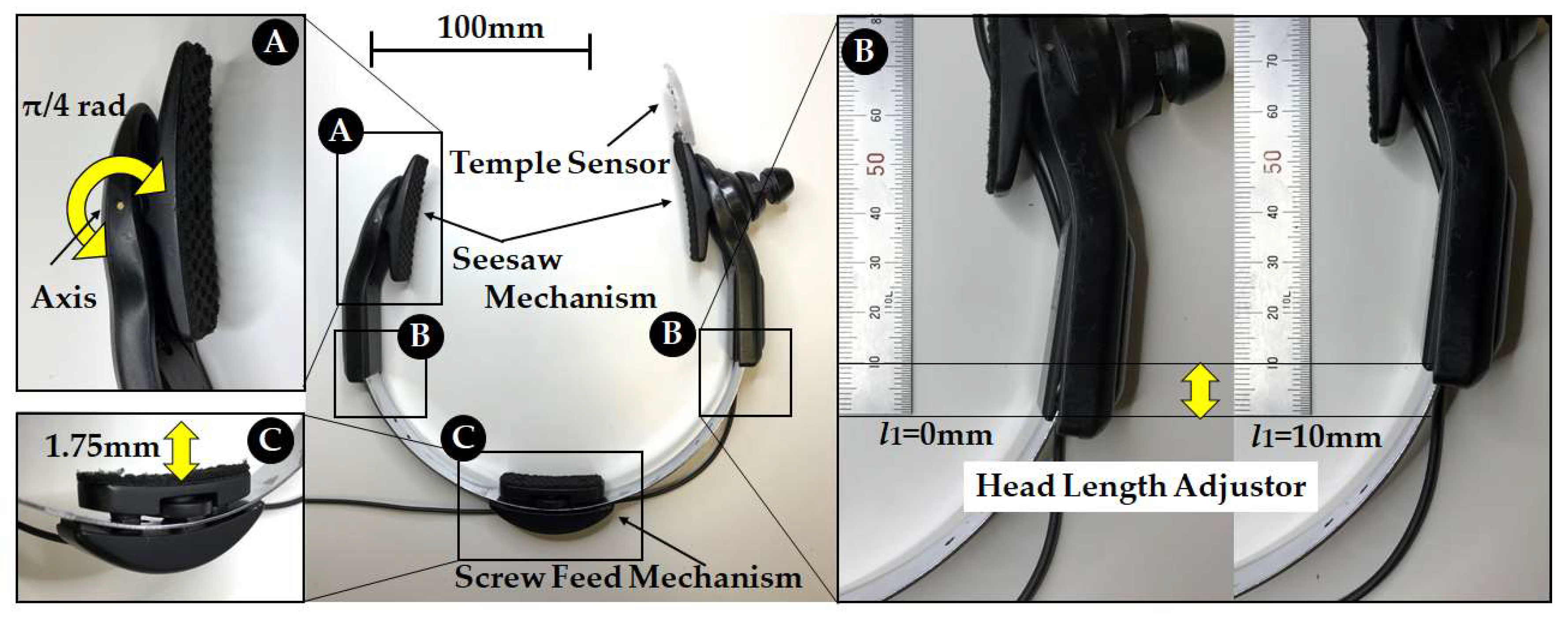
The test subjects had a head of between 150 mm and 165 mm. The head-mounted equipment shown in
Figure 2 and
Figure 3 fit the head of the participant well without being either too big or too small. For each test subject, B and C in
Figure 2 were adjusted so that the head-mounted equipment was fixed securely to the head of the participant, and the temple sensor was set so that it was positioned on the temple of the test subject. Test subjects for whom the head-mounted equipment did not match their heads, or those who felt uncomfortable due to the tightening (clamping force) of the head-mounted equipment, were excluded.
This study was approved by the “Shinshu University ethics committee concerning research into humans”, and research cooperation was obtained after fully explaining the research to subjects in advance. Additionally, for all tests, the mouthwitch (equipment attached to the head), was cleaned with a brush and then washed and disinfected with ethanol disinfectant in consideration of hygiene issues.
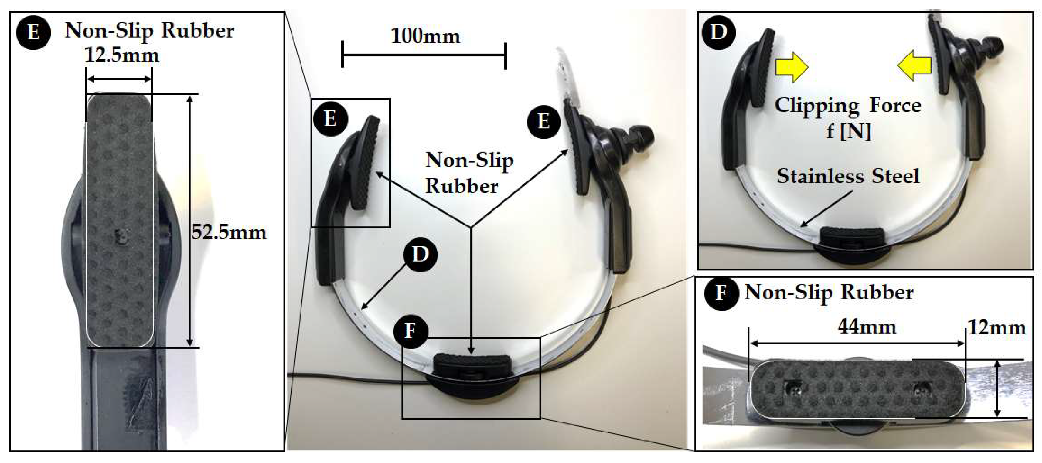
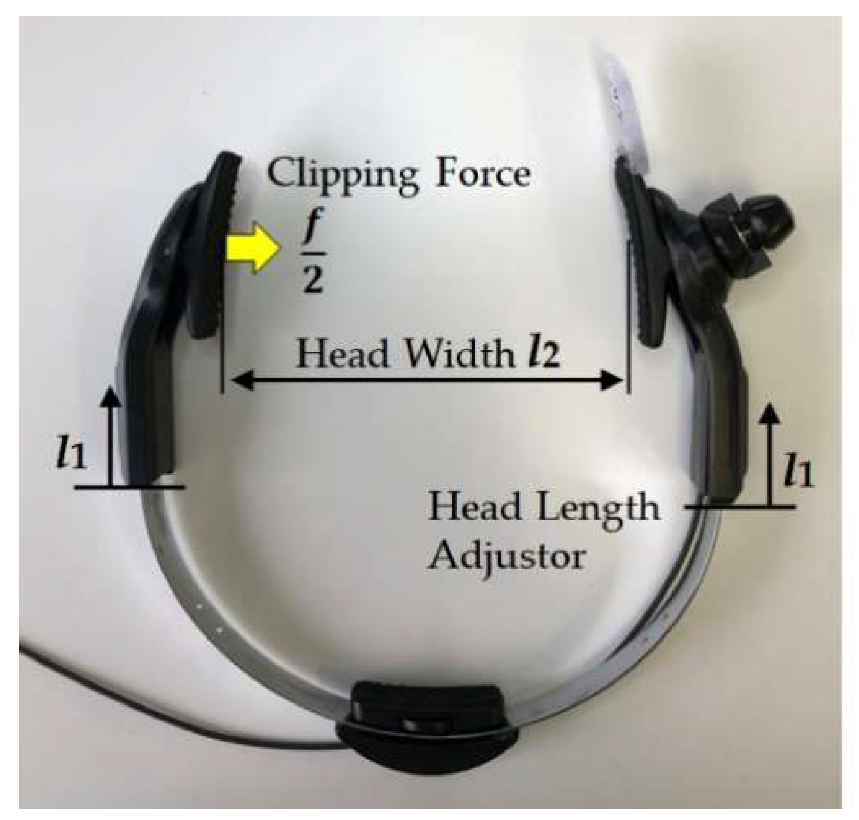
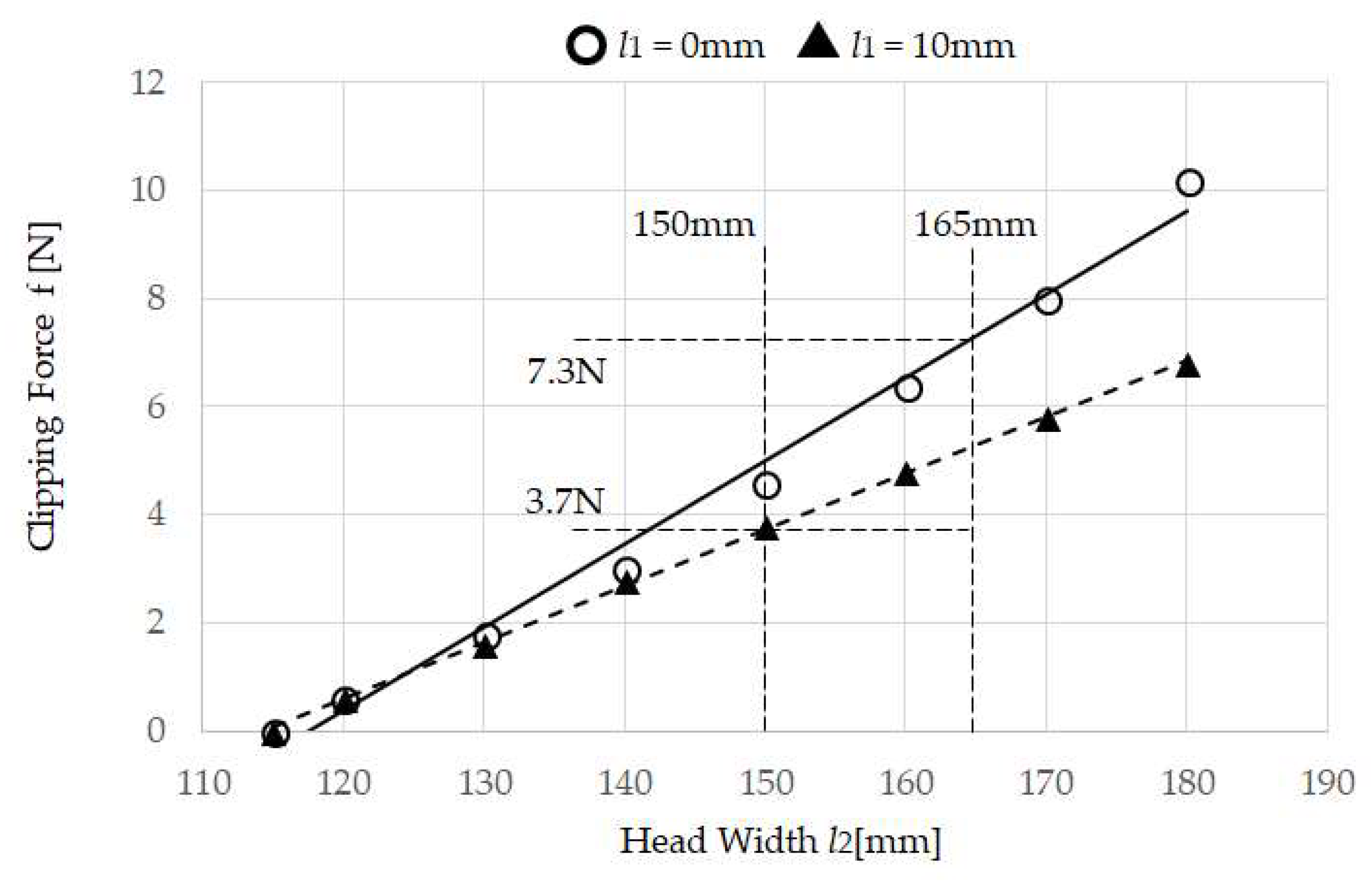
3.2. Measuring the Clipping Force f of Head-Mounted Equipment
The head-mounted equipment shown in
Figure 2 and
Figure 3 measures the relationship between clipping force f of the temporal area and the head width. When the Head Length Adjustor
l1 for the head-mounted equipment in
Figure 5 is changed within 0 and 10 mm, and when the Head Width
l2 is changed within 120 mm and 180 mm at 10 mm increments, Digital Force Gauge ZP-200N (IMADA Co., Ltd., Toyohashi, Japan) [
27] is used as the Clipping Force
f/2 N. Note that when the clipping Force
f/2 is ON (at non-load),
l2 is 115 mm.
3.3. Measurement of Data for Creating Ground Truth
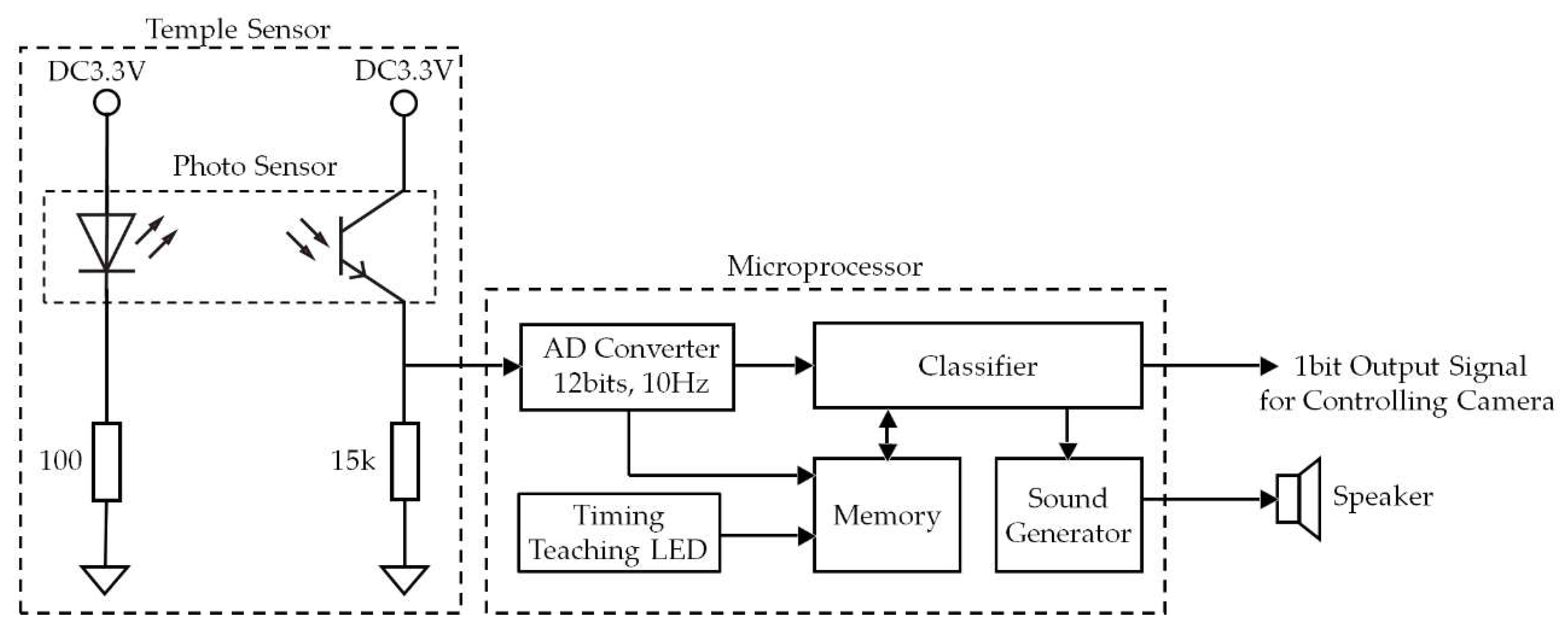
In the state where the temple sensor is attached to the head of the test subject, the “operation in which the mouth was opened for 1 s and then closed (TMC)” was executed 110 times to match the timing in which the LED to indicate timing was lit up, and the value measured by the temple sensor at that time was recorded. This measurement was carried out indoors so that sunlight did not influence the temple sensor.
From the measurement results using the method in
Section 2.2, ground truth was performed once for each test subject. The LED to indicate timing was repeated ten times with 1 s ON and 1 s OFF.
3.4. Mouthwitch Evaluation Test
This evaluation test evaluated performance when resting, speaking, chewing (chewing gum), walking, and running. The speaking test was carried out to investigate the effect that moving the mouth when speaking had on the mouthwitch operation (judgment of TMC). The gum chewing test was conducted to investigate the extent of the effect that such an action had on the judgment of TMC because the temporal muscles are also extended and contracted when chewing. The walking and running tests were conducted to investigate what effects body oscillations conducted for the purposes of walking or running have on the mouthwitch TMC judgment.
In this evaluation test, the test subjects rested for 180 s, then stated each of the alphabet letters from A, B, and C to Z once, chewed gum 100 times, walked for 80 s, and engaged in running for 80 s. Furthermore, in accordance with the lighting up of the timing indicator LED, the subjects carried out TMC 10 times each. For the gum chewing test, 3.0 g of gum (LOTTE Co., Ltd., Tokyo, Japan) [
28] was chewed. The 80 s of walking involved the total time for 10 TMC of approximately 2 s each time, and 60 s spent not performing TMC. The timing indicator LED had the lighting timing set in accordance with the test content in advance. In the speaking test, when performing TMC, A, B, and C to Z were not vocalized, and these were spoken between TMC and TMC. Additionally, as in the gum chewing test, the chewing of gum was not performed during the time of TMC only and, during this time, the gum was kept in the subject’s mouth, with chewing of the gum only taking place between TMC and TMC.
In this test, the ground truth was set in advance in the memory of the test device in accordance with the test subject. Every time measurement was performed with the temple sensor (every 0.1 s), the correlation coefficient with ground truth was calculated, and when the correlation coefficient value was 0.9 or higher, the sound “Do (C)” was generated as the shutter sound, instead of operating the shutter, and played from the speakers.
The timing indicator LED lighting situation, the temple sensor measurement values, and the correlation coefficient between the measurement value and ground truth, were automatically recorded in the tablet terminal connected to the device in
Figure 1.
This measurement was carried out indoors so that environmental light, such as sunlight, did not influence the temple sensor.
3.5. Head-Mounted Equipment Evaluation Test
In these evaluation tests, we investigated the impact on the TMC measurement results of reattaching the mouthwitch and using it over a long period of time, to evaluate the head-mounted equipment. We asked test subject G to attach and remove the mouthwitch 20 times, and perform TMC once, matching the flashing of the timing display LED every time it is reattached. We recorded the correlation coefficient of the TMC measurement values and the ground truth over 20 times. Next, we asked test subject G to attach the mouthwitch and perform TMC 10 times, matching the flashing of the timing display LED. Following this, we asked the subject to watch a 60-min drama with the mouthwitch continuously attached. The drama that test subject G was asked to watch was the TV drama “Bewitched”, which was broadcast in America in 1964. After watching the drama, they were asked to perform TMC 10 more times, matching the flashing of the timing display LED. Then we recorded the correlation coefficient of the TMC measurement values and the ground truth over these 20 times.
5. Discussion
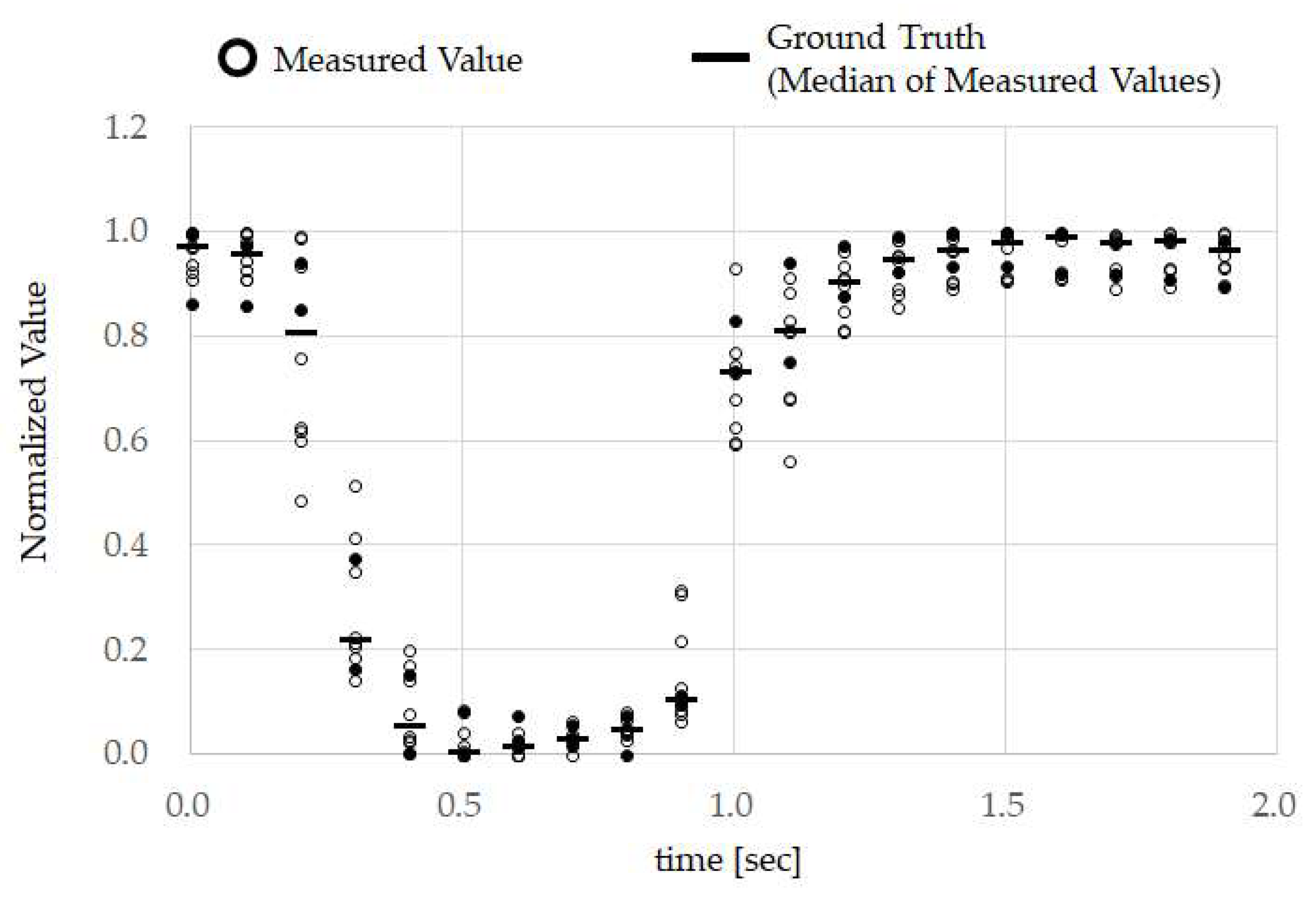
From the results in
Figure 7, it can be seen that, when test subject A opened their mouth, the normalized calculation values decreased, and when they closed their mouth, the values increased. In other words, we can also see that performing TMC made the calculation wave take on a “U” shape. Furthermore, from
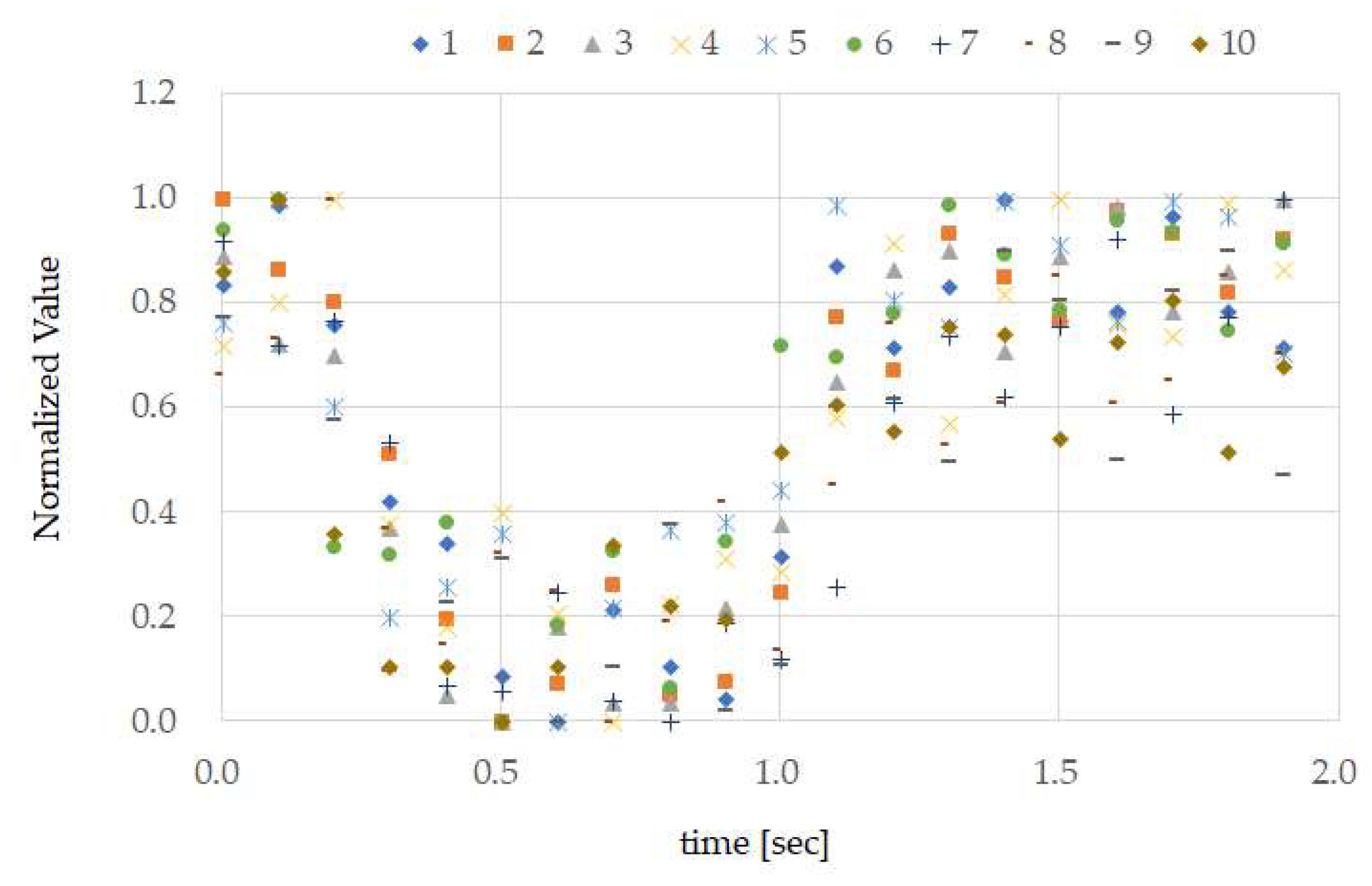
Figure 7, we can see that there was high reproducibility in TMC. From the ground truth in
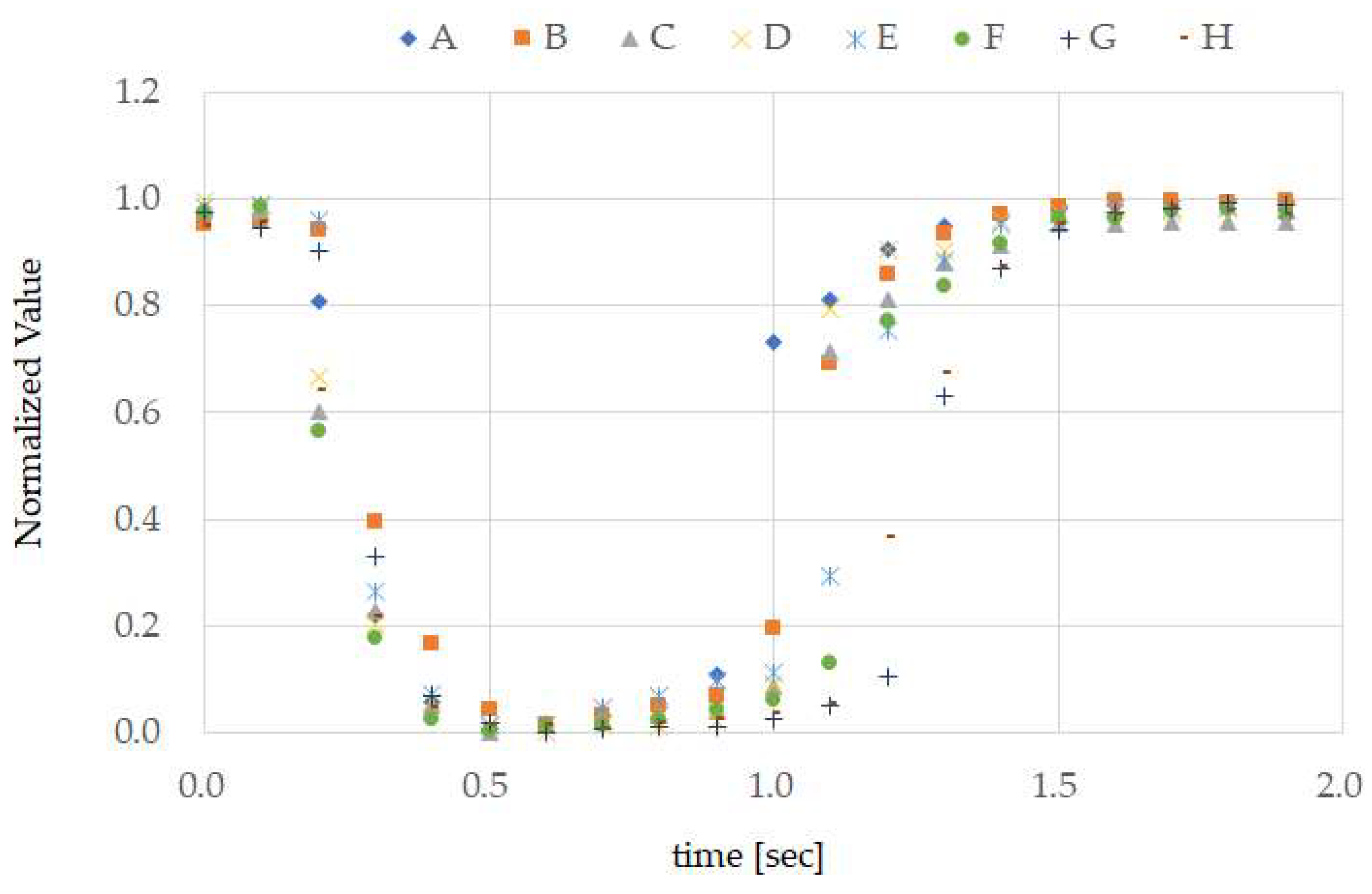
Figure 8, it is evident that the TMC calculation wave is “U”-shaped for other test subjects as well. Although not shown in this paper, there was also high reproducibility of TMC from test subjects B to H. The difference in ground truth with other test subjects shown in
Figure 8 was the time during which the mouth was continually open. As, in this way, consistency was seen in the measurement results of the small number of 8 test subjects with different genders and ages, and sufficient investigation may be possible even with this number.
The mean values for
accuracy when speaking and running from
Table 1 were 0.002 lower than the comparative figures for other operations. The values are not thought to be at such a low level as to be problematic. As speaking and running are operations that are accompanied by the opening and closing of the mouth, the opening and closing of the mouth is a common point with TMC. It is thought that this common point influenced
accuracy.
From the
precision results in
Table 1, we can see that there were no cases of mouthwitch mistakenly judging TMC even though the test subject had not performed TMC. Incidentally, one opens and closes one’s mouth when breathing while running; however, because this movement is different from opening one’s mouth for 1 s continuously and then closing it (TMC), mouthwitch does not mis-detect breathing while running for TMC.
As we can see from
recall in
Table 1, despite test subjects A, B, C, and D performing TMC while running, there were times when this was not classified as TMC by the classifier. Additionally, even though test subjects F and H performed TMC while speaking and walking, there were times when this was not classified as TMC by the classifier. These facts were observed using the results in
Figure 8. If we focus on the normalized values of each test subject from 1.0 to 1.5 s on the time axis in
Figure 8, we can see that, compared to test subjects A, B, C, and D, the time opening their mouth from 0.1 to around 0.3 s appears to be longer. Running, compared to speaking and walking, requires a faster breathing tempo and larger bodily movements (movements that are more frenetic within the unit time). In other words, when running, it is considered that the noise overlapping the temple sensors had a higher frequency compared to that when speaking and walking. Based on this, we can see that compared to movements with a high noise frequency, such as running,
recall of low frequency TMC generated by lengthening the time that the mouth is opened has a better score. On the other hand, compared to slower movements, such as speaking and walking (movements with a low noise frequency), high frequency TMC generated by shortening the time the mouth is continually opened, and
recall has a better score. As shown in
Figure 9, the temple sensor measurement waveform is distorted when running. This is because, for the signal due to TMC, the amplitude of noise from breathing when running, and breathing and head-mounted equipment vibration when running, is too large to ignore. This high amplitude noise is linked to a reduction in
recall. There is a method of increasing clip force f, as a means of preventing vibration in the head-mounted equipment. A method in which the area of the Non-Slip Rubber shown in
Figure 3 is increased, and the material of the Non-Slip Rubber is changed to absorb more vibration, can be considered. As methods that increase the clipping force f raise the physical burden on the test subject, moving forward, we would like to proceed with a method of improving the Non-Slip Rubber. If we consider that mouthwitch will be used in everyday scenarios, this may not be used because photo blur may occur when taking pictures while running. Therefore, in addition to improving
recall when running, it is also necessary to equip it with a function to track vibration and to adjust the shutter speed.
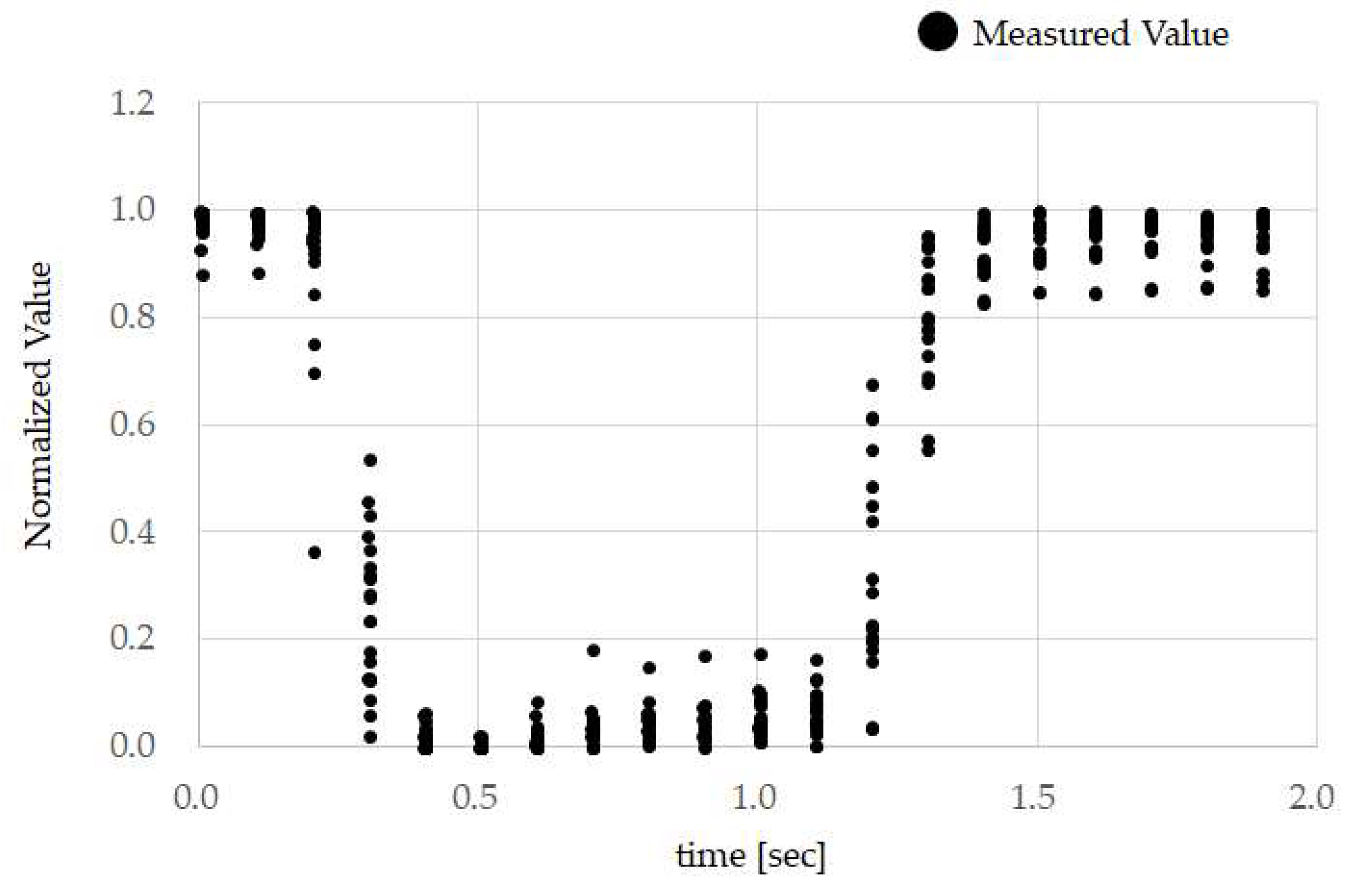
Based on the results of
Figure 10, the correlation coefficient between ground truth and TMC was maintained, even when reattaching the mouthwitch. From the results of
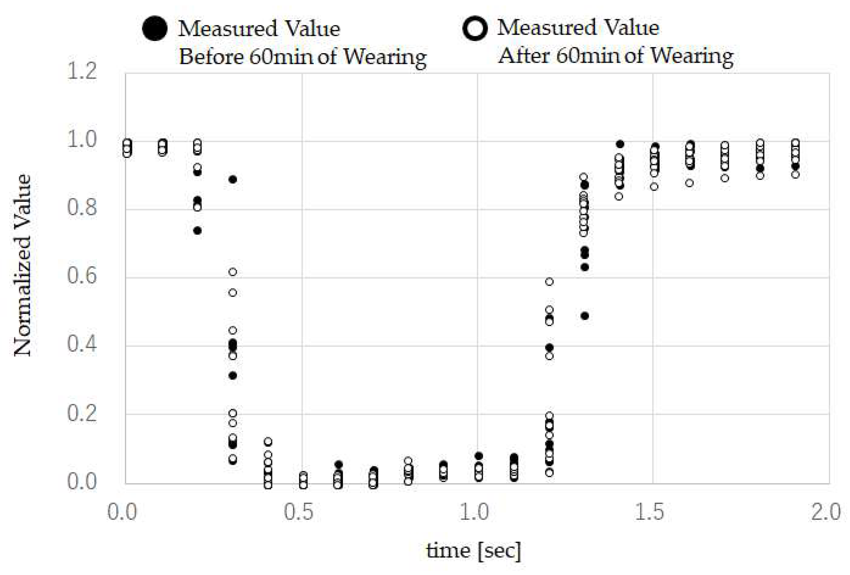
Figure 11, the correlation coefficient between ground truth and TMC was maintained, even after continuing to attach the mouthwitch continuously for 60 min. These results suggest that calibration is not required when reattaching the mouthwitch, or when using it over a long period of time. This also shows that the head-mount equipment was fixed securely to the head of test subject G.
Through verification tests, we can see that TMC has high reproducibility when resting, and this can be carried out rapidly, and performed simply and correctly without the test subject practicing.
These results suggest that TMC is suitable for movements where the objective is to operate a camera. Because mouthwitch can be integrated with headphones, it is highly compatible with devices that handle voice information, and because it does not obstruct your line of sight, it can be safely used in everyday life. For this reason, in addition to cameras, this can also be utilized for hands-free operation for devices, such as smartphones and music players, that are currently operated by hand. This may also lead to the development of wearable devices with new concepts using the mouthwitch. In the future, we would like to increase the number of temple sensors and place them on both the left and right temples, thus expanding the current 1-bit switch function to 2 bits.
Because the temple sensor uses an infrared sensor, sunlight that includes strong infrared waves is thought to affect the temple sensor measurement values. Moving forward, we need to survey this impact, and, where necessary, improve the temple sensor blocking cover, and provide environmental light filtering through signal processing, such as with modulation and demodulation technology. Additionally, since the user operates the shutter operation by opening and closing the mouth with mouthwitch, the gestures for this operation may cause those who do not know what mouthwitch is to feel that the TMC movements are strange. When looking at the user performing TMC, the subject may laugh, and this may make a good picture, but in a serious situation, the user may be mistaken for making light of the situation with the opening and closing of their mouth; therefore, when using mouthwitch, depending on the situation, it may be necessary for the user to cover their mouth with a mask. Additionally, so that the user easily understands that they can operate the shutter by opening and closing their mouth, it is necessary to raise awareness by using a signifier on the main unit of the mouthwitch, such as by displaying an icon [
29,
30,
31]. In this way, in consideration of the actual operation of mouthwitch, it is also necessary for any proposal to consider customs and etiquette. By continuing to resolve the aforementioned issues and improving the tests and systems in a variety of environments, we aim to make mouthwitch a more practical solution.
6. Conclusions
We have developed a head-mounted camera operation interface (mouthwitch) in which the taking of pictures with a compact, lightweight head-mounted camera can be achieved, hands-free, by “opening your mouth continuously for approximately one second and then closing it again (TMC)”. Mouthwitch, using the originally developed temple sensor, optically measures changes in the shape of the temples that occur when the mouth is opened and closed. Based on these measurement results, the mouthwitch then judges whether this is TMC in which the user is intending to operate the camera shutter and, based on these measurement results, sends the shutter operation 1-bit control signal to the camera. The prototype in this paper is not equipped with a camera and, instead of this, when the prototype recognizes TMC, it outputs a “Do” noise, as a shutter noise, from the speakers.
We performed tests to evaluate the operations of mouthwitch in 8 subjects (males and females from 21 to 44 years old), when resting, speaking, chewing, walking and running. From these results, we confirmed that “opening your mouth continuously for approximately one second and then closing it again” could be performed reliably by all subjects, that the measurement results of shape changes that occur in the skin near the temples have high reproducibility, and that because they are performed swiftly, they are suitable for the camera shutter operation. Additionally, the mean values for accuracy across all 8 test subjects were 1.000 in case of resting, chewing, and walking, and 0.998 for speaking and running. At the same time, the mean precision values for all items was 1.000, and the recall mean values were 1.000 for resting and chewing, 0.988 for speaking, 0.975 for walking, and 0.875 for running. From the above results, we can see that, although there were times when the TMC performed by test subjects when running could not be recognized by the prototypes device, during the other items, TMC could be recognized with a high probability. Additionally, when the test subject could not perform TMC, this was not mis-detected by the prototype device as TMC.
Moving forward, we are aiming to improve recall when running and to improve the head-mounted equipment. Furthermore, we would like to consider customs and etiquette as matters requiring consideration when actually operating mouthwitch when making proposals. Additionally, we aim to improve tests and the system in a variety of environments and make mouthwitch a more practical solution.


