Self-Alignment MEMS IMU Method Based on the Rotation Modulation Technique on a Swing Base


Abstract
:1. Introduction
2. Coordinate Frame Definition
- (1)
- e frame: Earth-fixed frame, with its x- and y-axes fixed on the equatorial plane, with the z-axis fixed along the rotational axis of the earth.
- (2)
- i frame: Inertial frame, formed by the solidification of the earth coordinate system in inertial space.
- (3)
- n frame: Navigation frame. In this work, its x-, y-, and z-axes point to the local east, north, and upward, respectively, which are used for the navigation and attitude representation calculations.
- (4)
- b frame: Body frame. Its origin is at the center of the IMU and the x-, y-, and z-axes point to the right, front, and upward, respectively.
- (5)
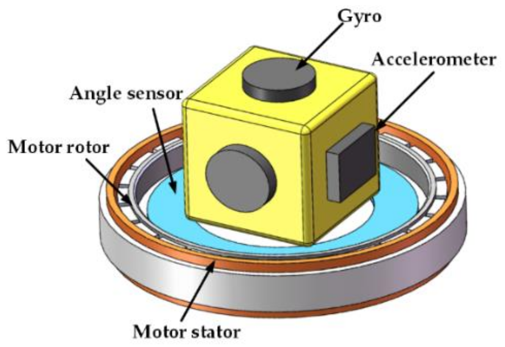
- s frame: IMU frame. Its axes coincide with the sensitive axes of the inertial sensors, and its origin is defined as the origin of the IMU. Additionally, the s frame turns in sync with the rotation of the IMU.
- (6)
- ib0 frame: Body inertial frame, formed by fixing the b frame in inertial space at the initial time of the inertial alignment process.
3. Rotation Modulation Technique
3.1. Rotation Modulation Technique Principle
3.2. Rotation Scheme Design
- (1)
- Number of rotating axes. Single axis rotation and dual axis rotation are both common rotation processes. Single axis rotation is inexpensive with a simple structure and high reliability, but it cannot modulate all constant errors. Dual axis rotation can modulate all constant errors, but the complexity and cost are greater. Considering the dual axis rotation scheme reduces the advantages of MEMS IMU, such as its low cost and small size, we decided to use the single axis rotation scheme.
- (2)
- Selection of the rotation axis. The selection of the rotation axis for MEMS IMU must consider that the error along the rotation axis cannot be modulated. Therefore, considering which axis rotation can minimize the effect of unmodulated errors on attitude is important. In the literature [5], gyro errors in the horizontal plane cause a larger attitude error, so the rotation scheme around the z-axis is better than the rotation around the x- or y-axis. Therefore, we chose the rotation scheme around the z-axis.
- (3)
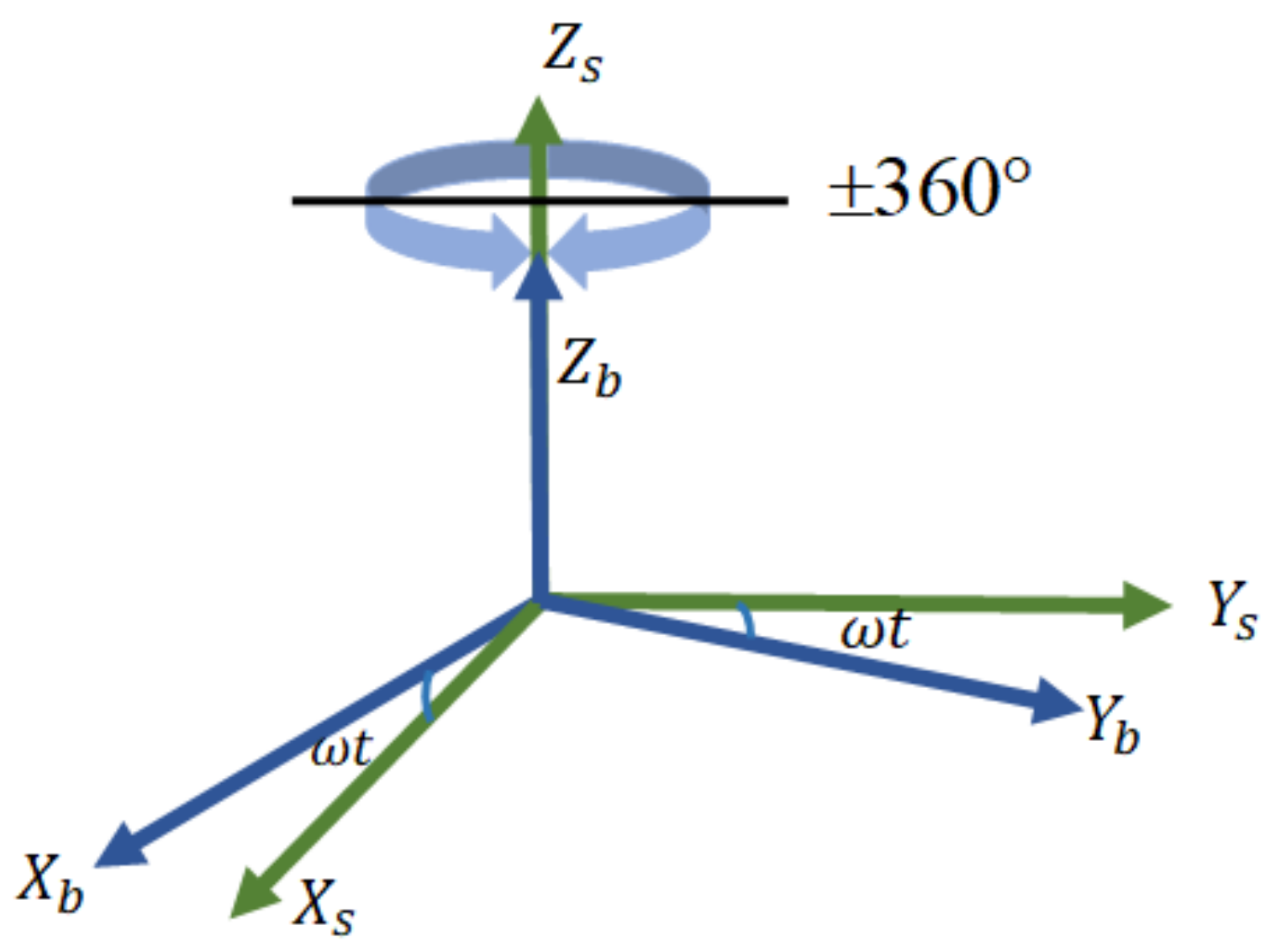
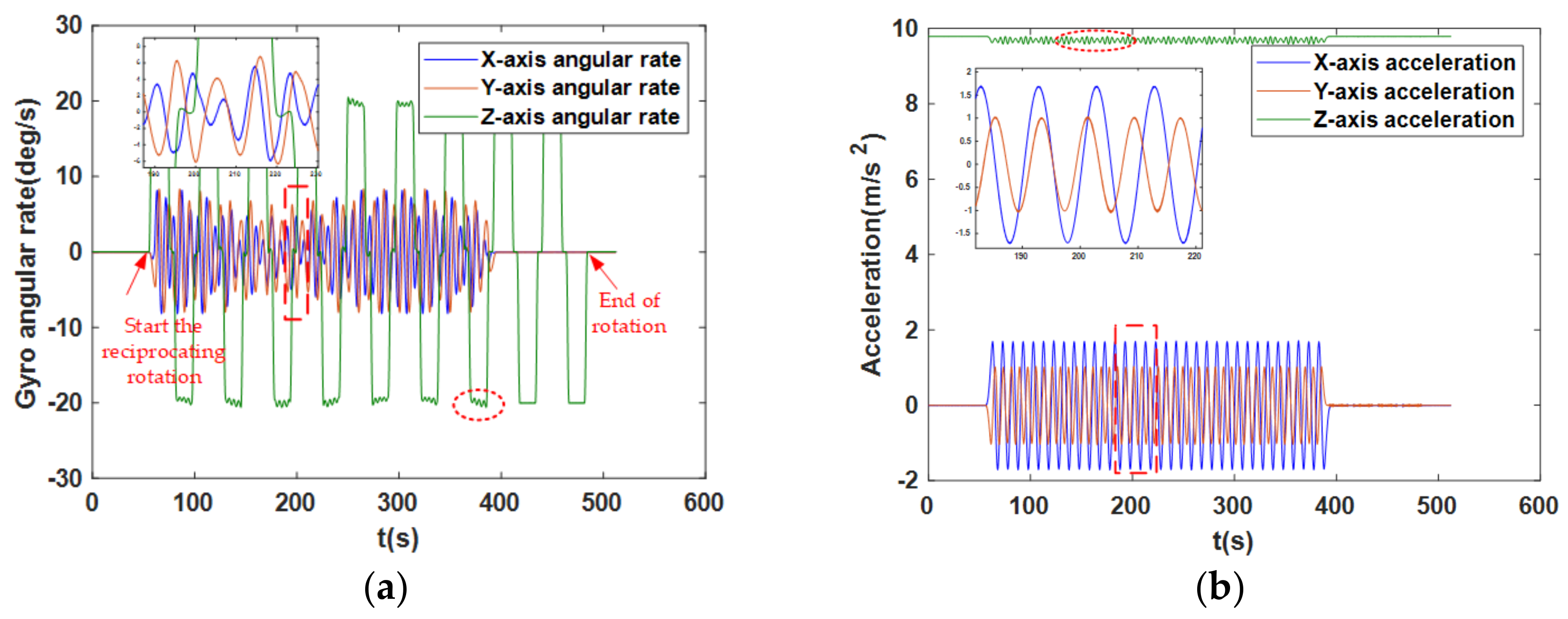
- Rotation direction. Two single axis rotation schemes, namely unidirectional rotation and reciprocation rotation, were discussed. The scale factors for gyros and accelerometers are usually considered to be constant in a relatively stable environment for a short time [5,44]. However, due to the existence of residual errors in the scale factor, the angular rate of unidirectional rotation coupled with the scale factor error creates a larger error. In contrast, the reciprocation rotation can offset the error caused by the scale factor [32]. As shown in Figure 3, a complete reciprocation rotation cycle includes 360 degrees of rotation about the z-axis in the counterclockwise (positive) direction, and then a rotation cycle in the clockwise (negative) direction. This method has been used in previous work [32,45], and was also used in this paper.
- (4)
- Rotation continuity. The reciprocation rotation scheme can be used for continuous rotation or an alternating rotating-stopping scheme. During continuous rotation, the constant error is modulated into a cosine signal. The alternate rotating-stopping scheme rotates a certain angle and stops at the current position before continuing to rotate to the next position. For high-end INS, the short-term stop time will not significantly impact the navigation error, but for the MEMS IMU, the navigation error be significantly increases when rotation stops [46]. Therefore, we used a continuous rotation scheme in this paper.
- (5)
- Angular rate of rotation. The RMT effect is related to the angular rate of rotation. Theoretically, the faster the rate of rotation, the more obvious the effect of error suppression [47,48]. However, for practical engineering applications, a too fast angular rate of rotation cause control difficulties, high frequency noise, and additional error caused by the motor. For high-end INS, a smaller rotational angular rate allows more precise control of the motor. Regardless, a high rotation rate can significantly inhibit the effect of the errors of MEMS inertial sensors. Therefore, the effect of error suppression should be considered, along with avoiding the direction transformation errors caused by the excessive rotation rate. Accordingly, a comprehensive consideration of the above factors and for convenience of calculation, the simulation and experimental rotational angular rate was set to 20°/s.
4. Rotating MEMS IMU Alignment Principle
4.1. Coarse Alignment
4.2. Fine Alignment
5. Simulation and Experimental Analysis
5.1. Simulation Test
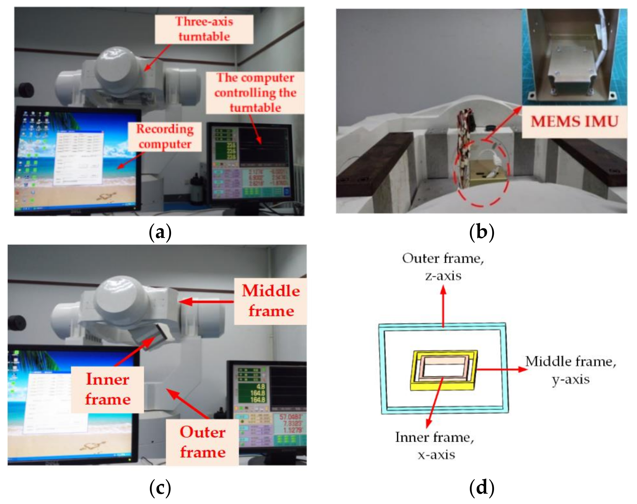
5.2. Physical Experiment Setup
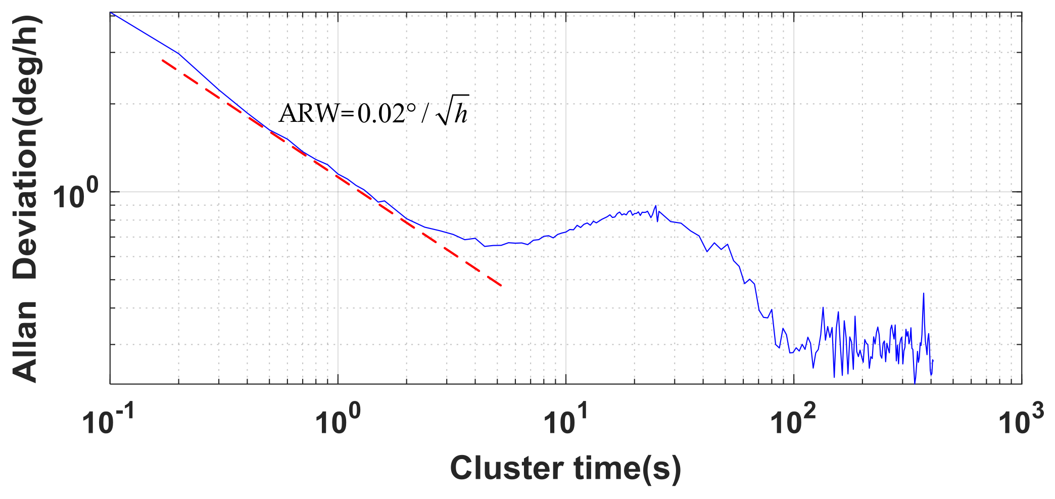
5.3. Allan Variance Method
5.4. Turntable-Based Alignment Experiment
5.5. Result Analysis
5.6. Irregularity of Platform Rotation Discussion
6. Conclusions
Acknowledgments
Author Contributions
Conflicts of Interest
References
- Deppe, O.; Dorner, G.; König, S.; Martin, T.; Voigt, S.; Zimmermann, S. MEMS and FOG Technologies for Tactical and Navigation Grade Inertial Sensors—Recent Improvements and Comparison. Sensors 2017, 17, 567. [Google Scholar] [CrossRef] [PubMed]
- Yamane, D.; Konishi, T.; Safu, T.; Tachibana, K.; Teranishi, M.; Chen, C.-Y.; Chang, T.-F.M.; Sone, M.; Machida, K.; Masu, K. Long-term vibration characteristics of MEMS inertial sensors by multi-layer metal technology. In Proceedings of the 2017 19th International Conference on Solid-State Sensors, Actuators and Microsystems (TRANSDUCERS), Kaohsiung, Taiwan, 18–22 June 2017; pp. 2187–2190. [Google Scholar]
- Du, S. Rotary Inertial Navigation System with a Low-cost MEMS IMU and Its Integration with GNSS. Ph.D. Thesis, University of Calgary, Calgary, AB, Canada, 2015. [Google Scholar]
- Zhang, Y.; Zhou, B.; Song, M.; Hou, B.; Xing, H.; Zhang, R. A Novel MEMS Gyro North Finder Design Based on the Rotation Modulation Technique. Sensors 2017, 17, 973. [Google Scholar] [CrossRef] [PubMed]
- Du, S.; Sun, W.; Gao, Y. MEMS IMU error mitigation using rotation modulation technique. Sensors 2016, 16, 2017. [Google Scholar] [CrossRef] [PubMed]
- Yang, B.; Xu, X.; Zhang, T.; Sun, J.; Liu, X. Novel SINS Initial Alignment Method under Large Misalignment Angles and Uncertain Noise Based on Nonlinear Filter. Math. Probl. Eng. 2017, 2017, 5917917. [Google Scholar] [CrossRef]
- Liu, M.; Gao, Y.; Li, G.; Guang, X.; Li, S. An improved alignment method for the Strapdown Inertial Navigation System (SINS). Sensors 2016, 16, 621. [Google Scholar] [CrossRef] [PubMed]
- Lu, B.; Wang, Q.; Yu, C.; Gao, W. Optimal parameter design of coarse alignment for fiber optic gyro inertial navigation system. Sensors 2015, 15, 15006–15032. [Google Scholar] [CrossRef] [PubMed]
- Jiancheng, F.; Sheng, Y. Study on innovation adaptive EKF for in-flight alignment of airborne POS. IEEE Trans. Instrum. Meas. 2011, 60, 1378–1388. [Google Scholar] [CrossRef]
- Li, H.; Pan, Q.; Wang, X.; Jiang, X.; Deng, L. Kalman filter design for initial precision alignment of a strapdown inertial navigation system on a rocking base. J. Navig. 2015, 68, 184–195. [Google Scholar] [CrossRef]
- Liu, X.; Xu, X.; Zhao, Y.; Wang, L.; Liu, Y. An initial alignment method for strapdown gyrocompass based on gravitational apparent motion in inertial frame. Measurement 2014, 55, 593–604. [Google Scholar] [CrossRef]
- Li, Q.; Ben, Y.; Yang, J. Coarse alignment for fiber optic gyro SINS with external velocity aid. Opt. Int. J. Light Electron. Opt. 2014, 125, 4241–4245. [Google Scholar] [CrossRef]
- Liu, X.; Liu, X.; Song, Q.; Yang, Y.; Liu, Y.; Wang, L. A novel self-alignment method for SINS based on three vectors of gravitational apparent motion in inertial frame. Measurement 2015, 62, 47–62. [Google Scholar] [CrossRef]
- Ma, T.; Gao, Y. Application and comparison of two methods for alignment of FOG SINS. In Proceedings of the 2010 8th World Congress on Intelligent Control and Automation, Jinan, China, 7–9 July 2010; pp. 3581–3584. [Google Scholar]
- Zhang, T.; Zhu, Y.; Zhou, F.; Yan, Y.; Tong, J. Coarse Alignment Technology on Moving Base for SINS Based on the Improved Quaternion Filter Algorithm. Sensors 2017, 17, 1424. [Google Scholar] [CrossRef] [PubMed]
- Havinga, M.C. Flight test results of a MEMS IMU based transfer alignment algorithm for short range air-to-air missiles. In Proceedings of the AIAA Guidance, Navigation, and Control (GNC) Conference, Boston, MA, USA, 19–22 August 2013; p. 5244. [Google Scholar]
- Chu, H.; Sun, T.; Zhang, B.; Zhang, H.; Chen, Y. Rapid Transfer Alignment of MEMS SINS Based on Adaptive Incremental Kalman Filter. Sensors 2017, 17, 152. [Google Scholar] [CrossRef] [PubMed]
- Gao, S.; Wei, W.; Zhong, Y.; Feng, Z. Rapid alignment method based on local observability analysis for strapdown inertial navigation system. Acta Astronaut. 2014, 94, 790–798. [Google Scholar]
- Li, T.; Zhang, H.; Niu, X.; Gao, Z. Tightly-Coupled Integration of Multi-GNSS Single-Frequency RTK and MEMS-IMU for Enhanced Positioning Performance. Sensors 2017, 17, 2462. [Google Scholar] [CrossRef] [PubMed]
- Wang, M.; Feng, G.; Yu, H.; Li, Y.; Yang, Y.; Xiao, X. A loosely coupled MEMS-SINS/GNSS integrated system for land vehicle navigation in urban areas. In Proceedings of the 2017 IEEE International Conference on Vehicular Electronics and Safety (ICVES), Vienna, Austria, 27–28 June 2017; pp. 103–108. [Google Scholar]
- Hu, Z.; Su, Y. Initial alignment of the MEMS inertial measurement system assisted by magnetometers. In Proceedings of the 2016 31st Youth Academic Annual Conference of Chinese Association of Automation (YAC), Wuhan, China, 11–13 November 2016; pp. 276–280. [Google Scholar]
- Wang, W.L.J. Effective Adaptive Kalman Filter for MEMS-IMU/Magnetometers Integrated Attitude and Heading Reference Systems. J. Navig. 2013, 66, 99–113. [Google Scholar]
- Wang, D.; Lv, H.; Wu, J. In-flight initial alignment for small UAV MEMS-based navigation via adaptive unscented Kalman filtering approach. Aerosp. Sci. Technol. 2017, 61, 73–84. [Google Scholar] [CrossRef]
- Wang, D.; Lv, H.; Wu, J. Augmented Cubature Kalman filter for nonlinear RTK/MIMU integrated navigation with non-additive noise. Measurement 2017, 97, 111–125. [Google Scholar] [CrossRef]
- Yuan, D.; Ma, X.; Liu, Y.; Zhang, C. Dynamic initial alignment of the MEMS-based low-cost SINS for AUV based on unscented Kalman filter. In Proceedings of the OCEANS 2016—Shanghai, Shanghai, China, 10–13 April 2016; pp. 1–6. [Google Scholar]
- Iozan, L.I.; Kirkkojaakkola, M.; Collin, J.; Takala, J.; Rusu, C. Using a MEMS gyroscope to measure the Earth’s rotation for gyrocompassing applications. Meas. Sci. Technol. 2012, 23, 025005. [Google Scholar] [CrossRef]
- Johnson, B.R.; Cabuz, E.; French, H.B.; Supino, R. Development of a MEMS gyroscope for northfinding applications. In Proceedings of the IEEE/ION Position, Location and Navigation Symposium, Indian Wells, CA, USA, 4–6 May 2010. [Google Scholar]
- Johnson, B.; Christ, K.; Endean, D.; Mohr, B.; Supino, R.; French, H.; Cabuz, E. Tuning fork MEMS gyroscope for precision northfinding. In Proceedings of the 2015 DGON Inertial Sensors and Systems Symposium (ISS), Karlsruhe, Germany, 22–23 September 2015; pp. 1–10. [Google Scholar]
- Jiang, Y.F. Error analysis of analytic coarse alignment methods. IEEE Trans. Aerosp. Electron. Syst. 2002, 34, 334–337. [Google Scholar] [CrossRef]
- Feng, S.; Tong, C. Accuracy analysis of coarse alignment based on gravity in inertial frame. Chin. J. Sci. Instrum. 2011, 32, 2409–2415. [Google Scholar]
- Hide, C.; Moore, T.; Hill, C.; Abdulrahim, K. Investigating the use of rotating foot mounted inertial sensors for positioning. In Proceedings of the 25th International Technical Meeting of The Satellite Division of the Institute of Navigation (ION GNSS 2012), Nashville, TN, USA, 17–21 September 2012. [Google Scholar]
- Sun, W.; Wang, D.; Xu, L.; Xu, L. MEMS-based rotary strapdown inertial navigation system. Measurement 2013, 46, 2585–2596. [Google Scholar] [CrossRef]
- Collin, J. MEMS IMU carouseling for ground vehicles. IEEE Trans. Veh. Technol. 2015, 64, 2242–2251. [Google Scholar] [CrossRef]
- Zhuo, P.; Rong, Z.; Guo, M.F.; Gang, L.; Luo, S.H. Strong tracking filter based SINS initial alignment for large misalignment angles. J. Chin. Inst. Technol. 2015. [Google Scholar] [CrossRef]
- Gao, Z.; Mu, D.; Gao, S.; Zhong, Y.; Gu, C. Robust adaptive filter allowing systematic model errors for transfer alignment. Aerosp. Sci. Technol. 2016, 59, 32–40. [Google Scholar] [CrossRef]
- Huang, C.; Su, W.; Liu, P.; Ma, M.; Huang, C.; Su, W.; Liu, P.; Ma, M. Application of Adaptive Kalman Filter Technique in Initial Alignment of Strapdown Inertial Navigation System. In Proceedings of the 29th Chinese Control Conference, Beijing, China, 29–31 July 2010; pp. 2087–2090. [Google Scholar]
- Ali, J.; Ushaq, M. A consistent and robust Kalman filter design for in-motion alignment of inertial navigation system. Measurement 2009, 42, 577–582. [Google Scholar] [CrossRef]
- Geller, E.S. Inertial System Platform Rotation. IEEE Trans. Aerosp. Electron. Syst. 1968, AES-4, 557–568. [Google Scholar] [CrossRef]
- Titterton, D.; Weston, J. Strapdown Inertial Navigation Technology. Aerosp. Electron. Syst. Mag. IEEE 2004, 20, 33–34. [Google Scholar] [CrossRef]
- Levinson, E.; Willcocks, M.; Ter Horst, J. The next generation marine inertial navigation is here now. In Proceedings of the 1994 Position Location and Navigation Symposium, Las Vegas, NV, USA, 11–15 April 1994; pp. 121–127. [Google Scholar]
- Levinson, E.; Majure, R. Accuracy Enhancement Techniques Applied to the Marine Ring Laser Inertial Navigator (MARLIN). Navigation 1987, 34, 64–86. [Google Scholar] [CrossRef]
- Heckman, D.W.; Baretela, L.M. Improved affordability of high precision submarine inertial navigation by insertion of rapidly developing fiber optic gyro technology. In Proceedings of the IEEE 2000 Position Location and Navigation Symposium (Cat. No. 00CH37062), San Diego, CA, USA, 13–16 March 2000; pp. 404–410. [Google Scholar]
- Jia, Y.; Li, S.; Qin, Y.; Cheng, R. Error Analysis and Compensation of MEMS Rotation Modulation Inertial Navigation System. IEEE Sens. J. 2018, 18, 2023–2030. [Google Scholar] [CrossRef]
- Niu, X.; Li, Y.; Zhang, H.; Wang, Q.; Ban, Y. Fast Thermal Calibration of Low-Grade Inertial Sensors and Inertial Measurement Units. Sensors 2013, 13, 12192–12217. [Google Scholar] [CrossRef] [PubMed]
- Zaitsev, D.; Antonov, A.; Krishtop, V. Angular MET sensor for precise azimuth determination. In Proceedings of the The International Conference on Micro- and Nano-Electronics, Zvenigorod, Russian, 30 December 2016; p. 102241H. [Google Scholar]
- Xu, T.; Wang, B.; Wang, X.Y. Research on Rotating Modulated Strap-Down Inertial Navigation System Based on Micro-Electro-Mechanical Systems (MEMS) Sensors (RMSINS). Appl. Mech. Mater. 2012, 148–149, 192–197. [Google Scholar] [CrossRef]
- Wang, X.; Wu, J.; Wang, T.X.W. Analysis and Verification of Rotation Modulation Effects on Inertial Navigation System based on MEMS Sensors. J. Navig. 2013, 66, 751–772. [Google Scholar] [CrossRef]
- Sun, F.; Sun, W.; Gao, W.; Ben, Y. Research on the technology of rotational motion for FOG strapdown inertial navigation system. In Proceedings of the 2009 International Conference on Mechatronics and Automation, Changchun, China, 9–12 August 2009; pp. 4913–4918. [Google Scholar]
- Gaiffe, T.; Cottreau, Y.; Faussot, N.; Hardy, G. Highly compact fiber optic gyrocompass for applications at depths up to 3000 meters. In Proceedings of the 2000 International Symposium on Underwater Technology (Cat. No. 00EX418), Tokyo, Japan, 26 May 2000; pp. 155–160. [Google Scholar]
- Sun, F.; Lan, H.; Yu, C.; Elsheimy, N.; Zhou, G.; Cao, T.; Liu, H. A Robust Self-Alignment Method for Ship’s Strapdown INS under Mooring Conditions. Sensors 2013, 13, 8103–8139. [Google Scholar] [CrossRef] [PubMed]
- Safarinejadian, B.; Yousefi, M. Static alignment of inertial navigation systems using an adaptive multiple fading factors Kalman filter. Syst. Sci. Control Eng. 2015, 3, 351–359. [Google Scholar] [CrossRef]
- Zhao, X.M.; Zhao, S.; Wang, X.L.; Zhou, L.F.; Wang, Q. In-motion alignment based on strong tracking filter. J. Chin. Inst. Technol. 2015, 23, 141–144. [Google Scholar]
- Wang, L.; Wu, L.; Guan, Y.; Wang, G. Online sensor fault detection based on an improved strong tracking filter. Sensors 2015, 15, 4578–4591. [Google Scholar] [CrossRef] [PubMed]
- Li, J.Q.; Zhao, R.H.; Chen, J.L.; Zhao, C.Y.; Zhu, Y.P. Target tracking algorithm based on adaptive strong tracking particle filter. IET Sci. Meas. Technol. 2016, 10, 704–710. [Google Scholar]
- Hou, H.; El-Sheimy, N. Inertial sensors errors modeling using Allan variance. In Proceedings of the 16th International Technical Meeting of the Satellite Division of The Institute of Navigation (ION GPS/GNSS 2003), Portland, OR, USA, 9–12 September 2003. [Google Scholar]


| Item | Pitch | Roll | Heading |
|---|---|---|---|
| Amplitude () | 5 | 8 | 10 |
| Cycle (s) | 6 | 7 | 5 |
| Swing center () | 0 | 0 | 30 |
| Axes | Gyro error | Accelerometer Error | ||
|---|---|---|---|---|
| Constant Drift () | Random Noise () | Constant Bias (μg) | Random Noise () | |
| x-axis | 10 | 0.02 | 100 | 10 |
| y-axis | 10 | 0.02 | 100 | 10 |
| z-axis | 10 | 0.02 | 100 | 10 |
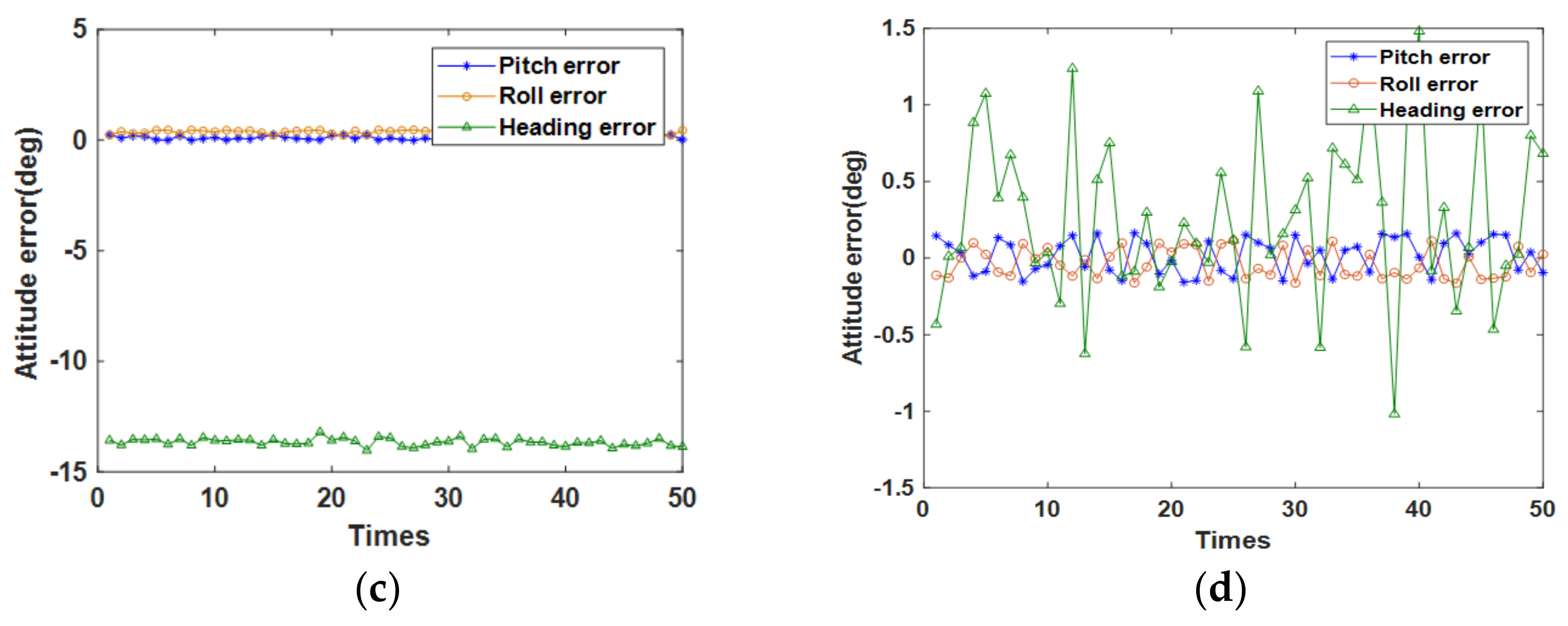
| Statistical Parameters | Pitch Error () | Roll Error () | Heading Error () |
|---|---|---|---|
| Mean () | 0.0189 | –0.0351 | 0.2667 |
| SD () | 0.1130 | 0.0963 | 0.5475 |
| Parameter | Gyro | Accelerometer |
|---|---|---|
| Repetitiveness of bias | (1) | 0.5 mg (1) |
| Random noise | ||
| Measuring range | ±300°/s | ±20 g |
| Items | Inner frame | Middle frame | Outer frame |
|---|---|---|---|
| Amplitude () | 6 | 10 | - |
| Frequency (Hz) | 0.125 | 0.1 | - |
| Rotation rate (/s) | - | - | 20 |
| Item | Inner Frame | Middle Frame | Outer Frame |
|---|---|---|---|
| Amplitude () | - | 6 | 10 |
| Frequency (Hz) | - | 0.125 | 0.1 |
| Rotation rate (/s) | 20 | - | - |
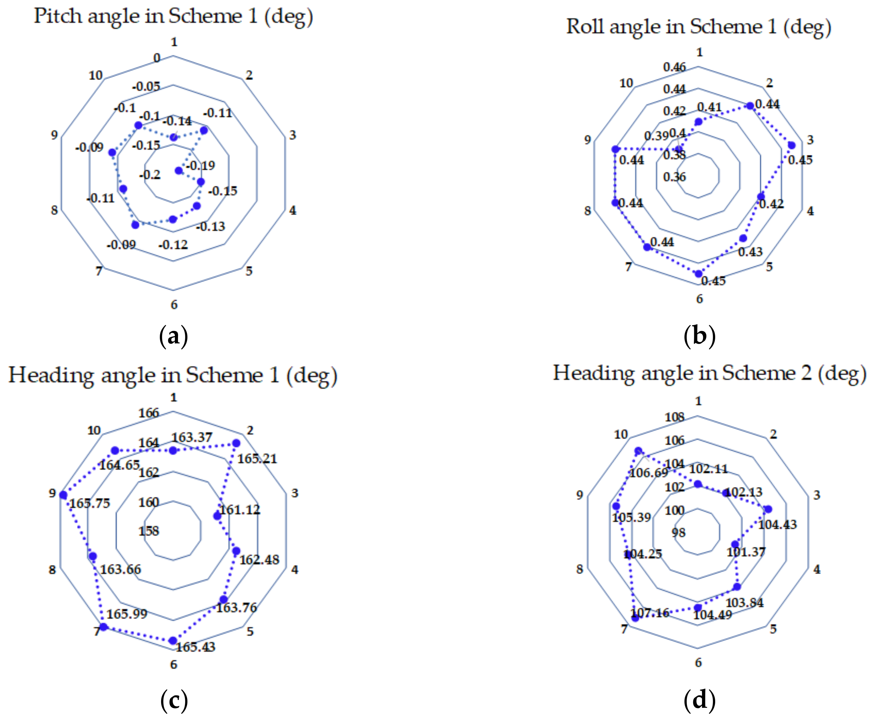
| Statistical Parameters | Pitch Angle () | Roll Angle () | Heading Angle () |
|---|---|---|---|
| Mean | 0.12 | 0.43 | 164.17 |
| SD | 0.03 | 0.02 | 1.49 |
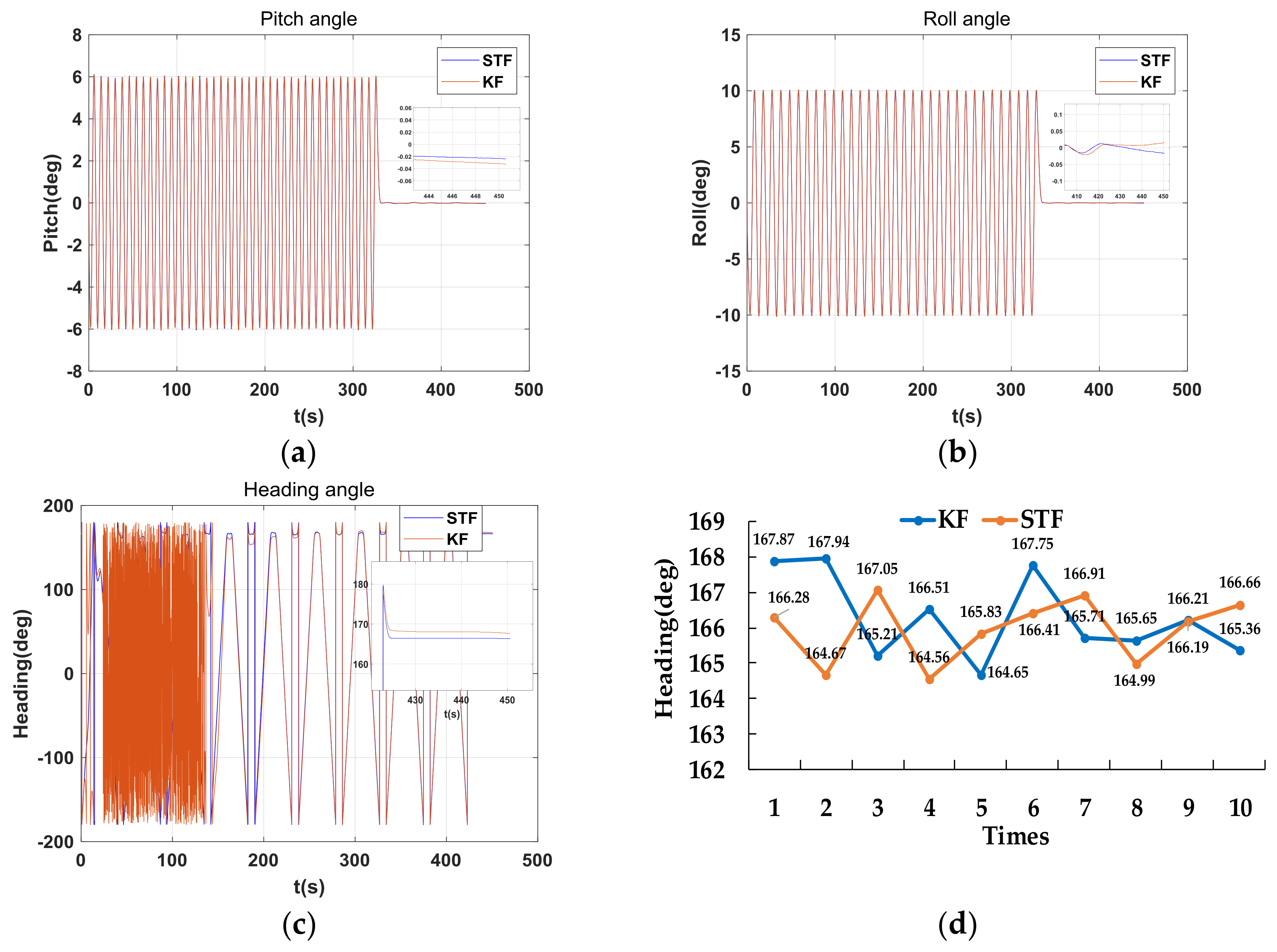
| Filtering Method | Pitch () | Roll () | Heading () | |||
|---|---|---|---|---|---|---|
| Mean | SD | Mean | SD | Mean | SD | |
| KF | 0.0041 | 0.0183 | 0.0035 | 0.0139 | 166.29 | 1.20 |
| STF | 0.0140 | 0.0097 | 165.96 | 0.91 | ||
© 2018 by the authors. Licensee MDPI, Basel, Switzerland. This article is an open access article distributed under the terms and conditions of the Creative Commons Attribution (CC BY) license (http://creativecommons.org/licenses/by/4.0/).
Share and Cite
Xing, H.; Chen, Z.; Yang, H.; Wang, C.; Lin, Z.; Guo, M. Self-Alignment MEMS IMU Method Based on the Rotation Modulation Technique on a Swing Base. Sensors 2018, 18, 1178. https://doi.org/10.3390/s18041178
Xing H, Chen Z, Yang H, Wang C, Lin Z, Guo M. Self-Alignment MEMS IMU Method Based on the Rotation Modulation Technique on a Swing Base. Sensors. 2018; 18(4):1178. https://doi.org/10.3390/s18041178
Chicago/Turabian StyleXing, Haifeng, Zhiyong Chen, Haotian Yang, Chengbin Wang, Zhihui Lin, and Meifeng Guo. 2018. "Self-Alignment MEMS IMU Method Based on the Rotation Modulation Technique on a Swing Base" Sensors 18, no. 4: 1178. https://doi.org/10.3390/s18041178
APA StyleXing, H., Chen, Z., Yang, H., Wang, C., Lin, Z., & Guo, M. (2018). Self-Alignment MEMS IMU Method Based on the Rotation Modulation Technique on a Swing Base. Sensors, 18(4), 1178. https://doi.org/10.3390/s18041178