A Rotational Gyroscope with a Water-Film Bearing Based on Magnetic Self-Restoring Effect

 , ,
, , 
Abstract
:1. Introduction
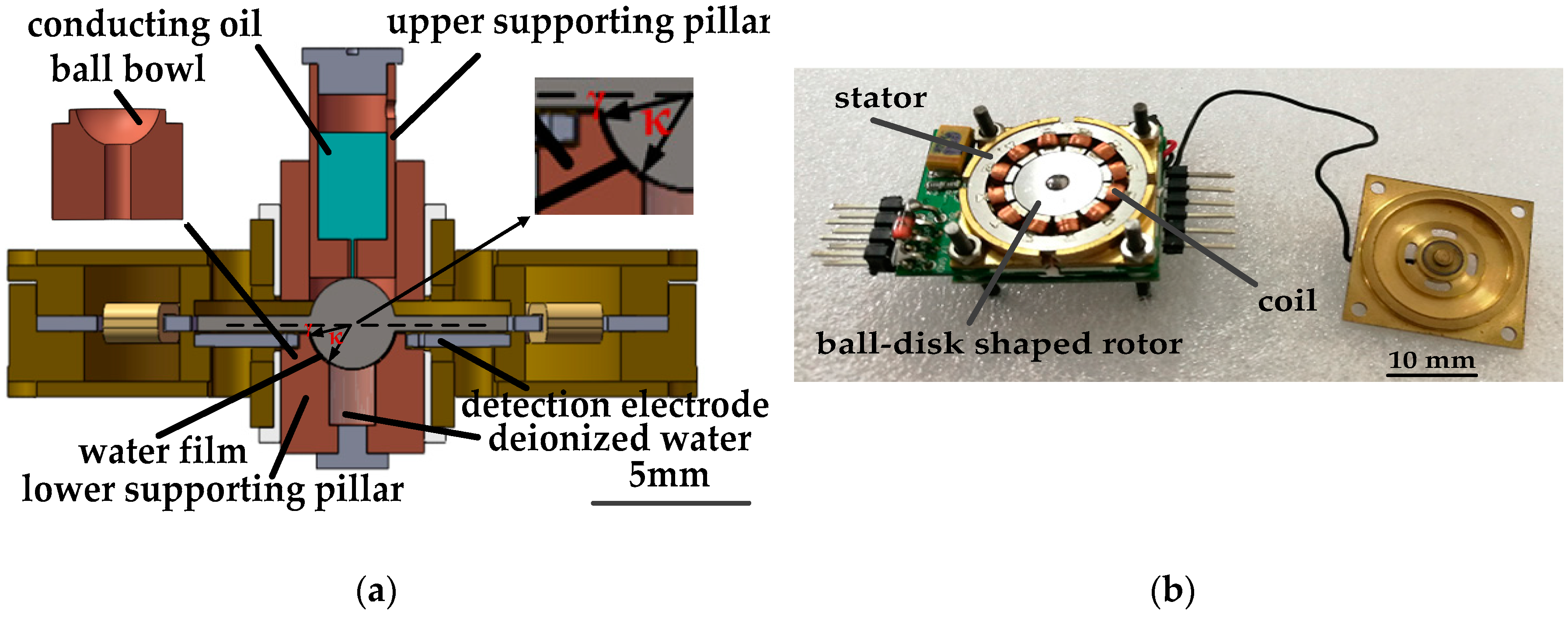
2. Structure Design
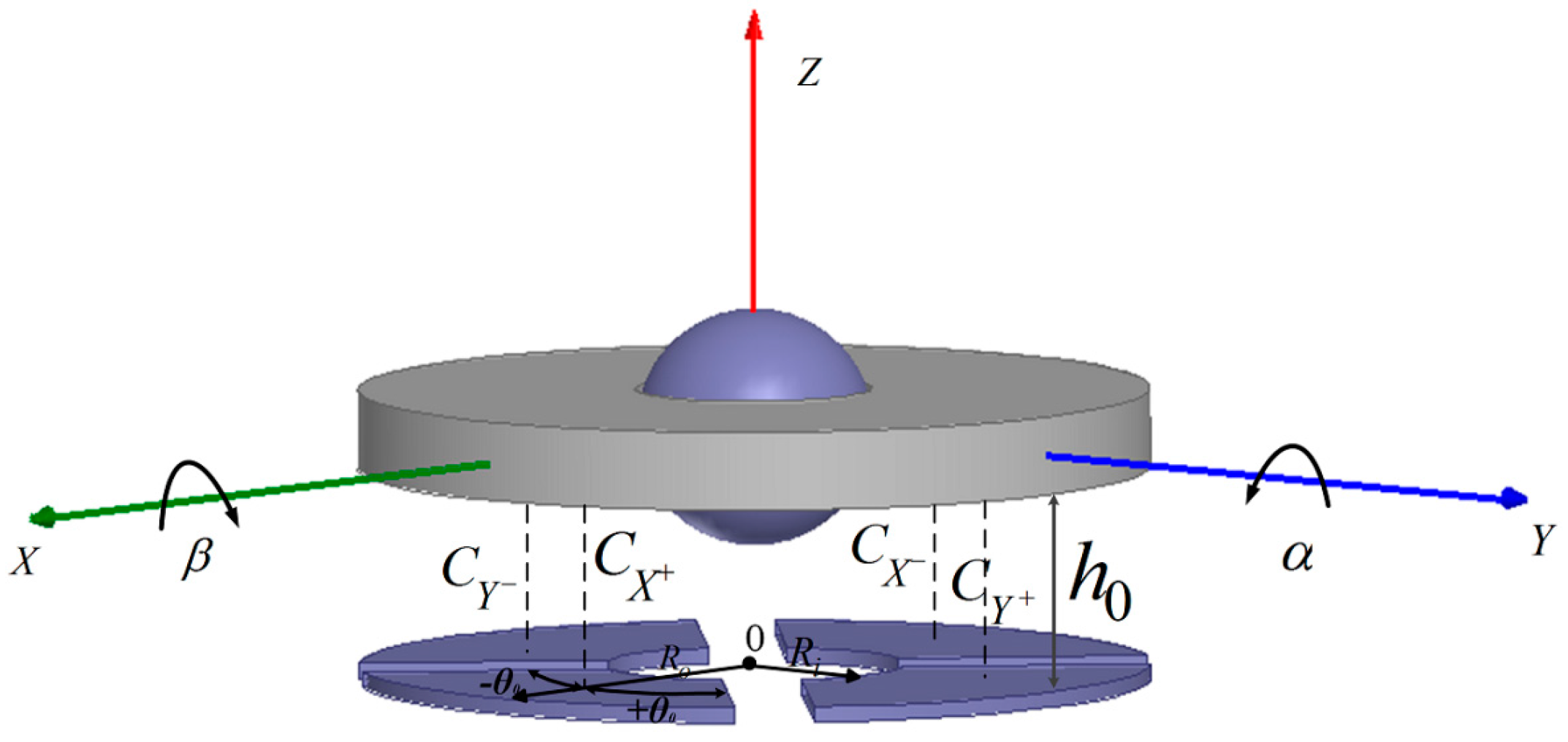
2.1. Mechanical Structure
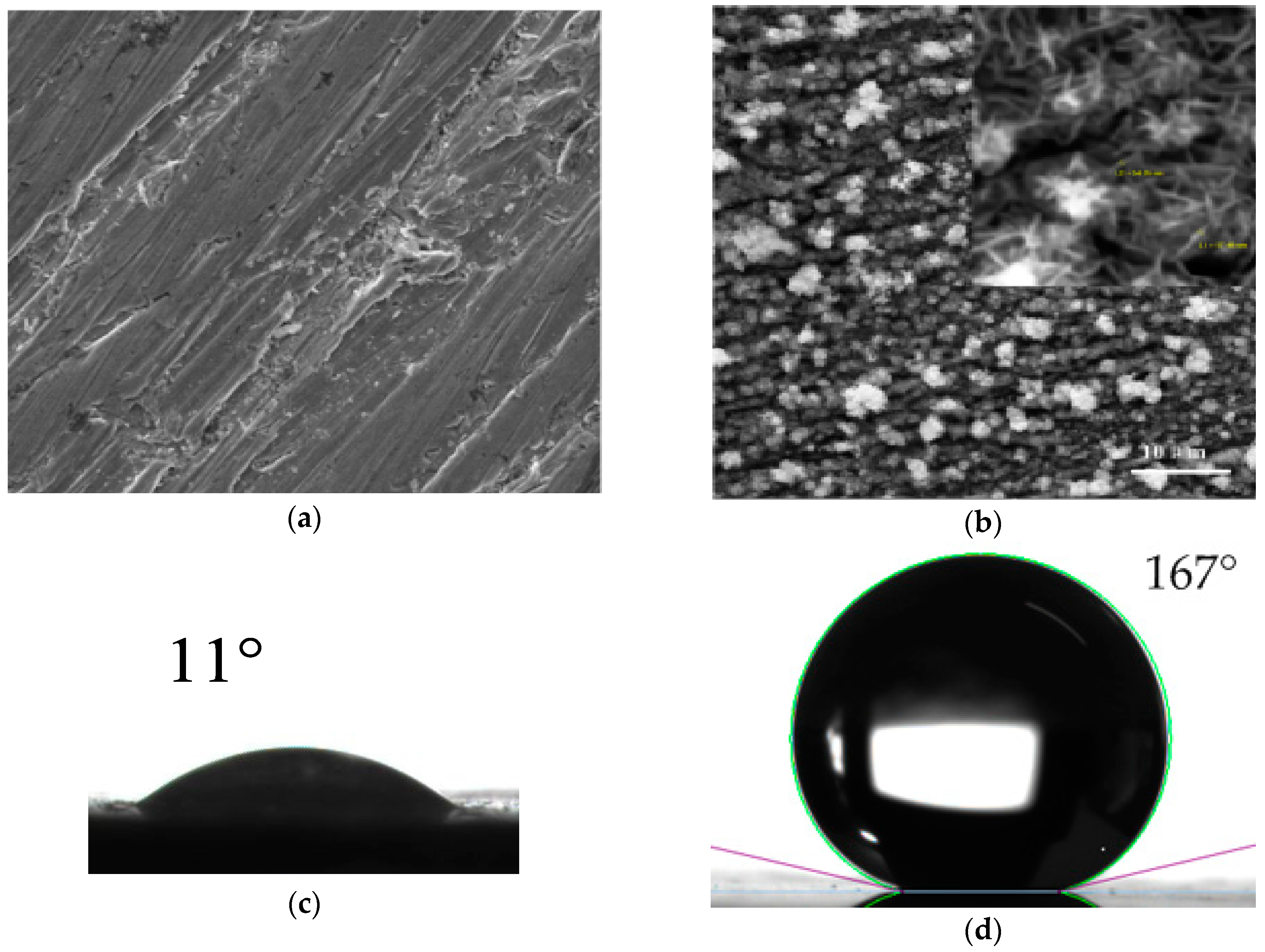
2.2. Fabrication of SHS on the Rotor Ball
3. Operational Principle
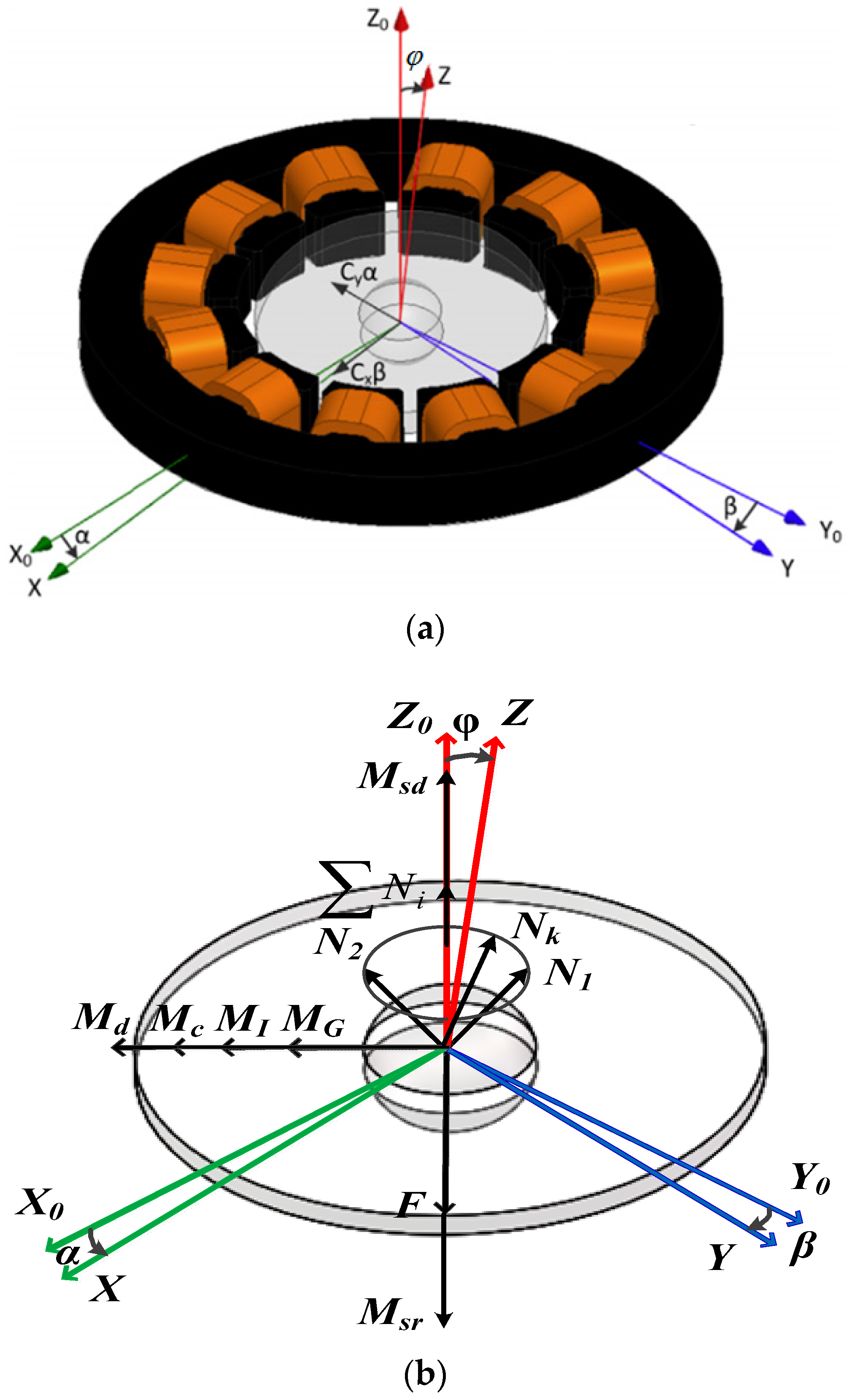
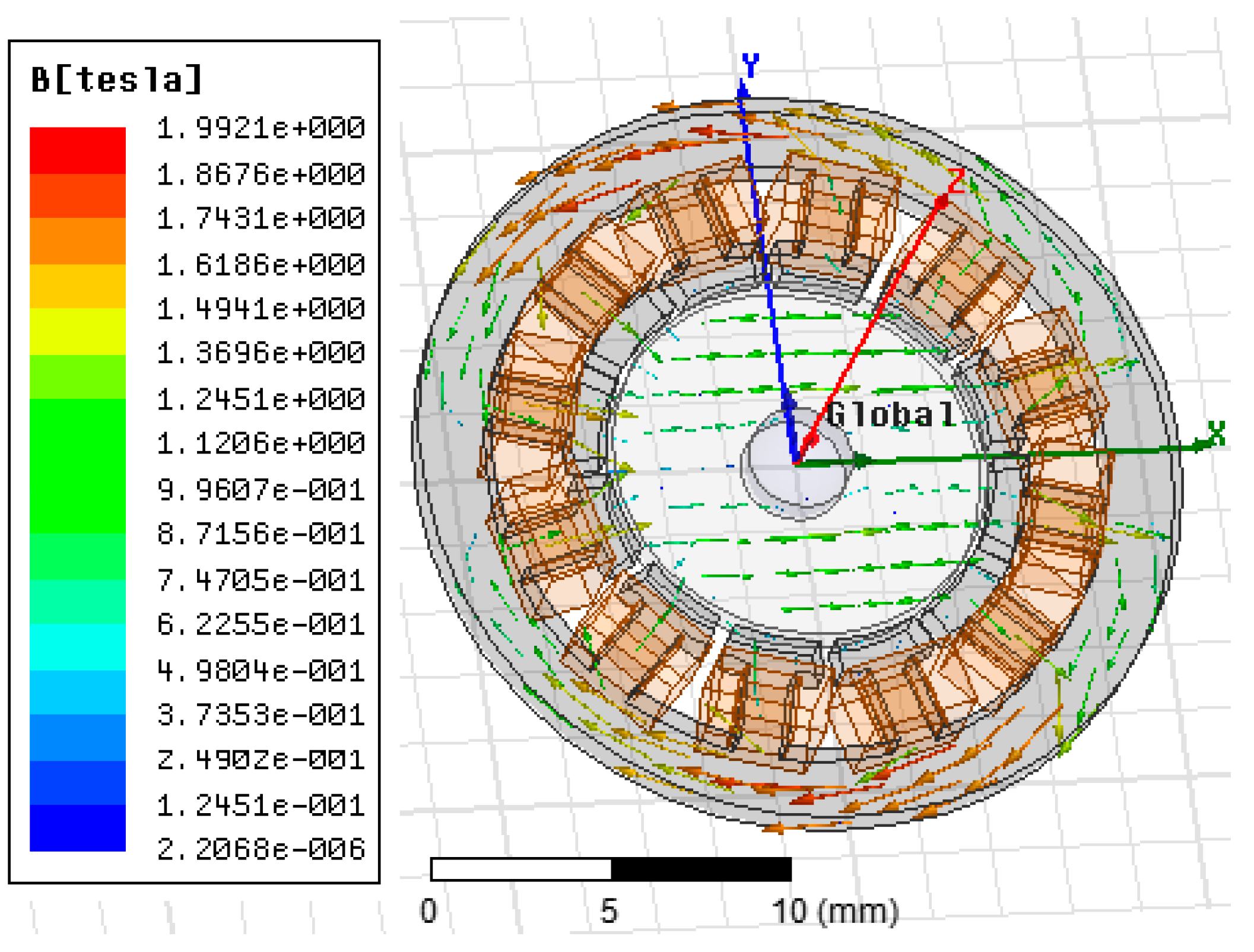
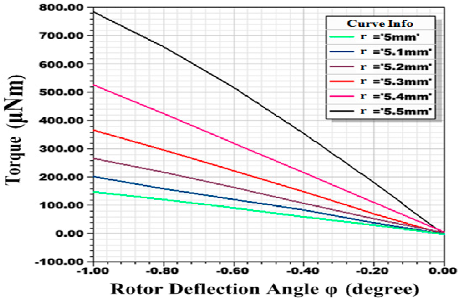
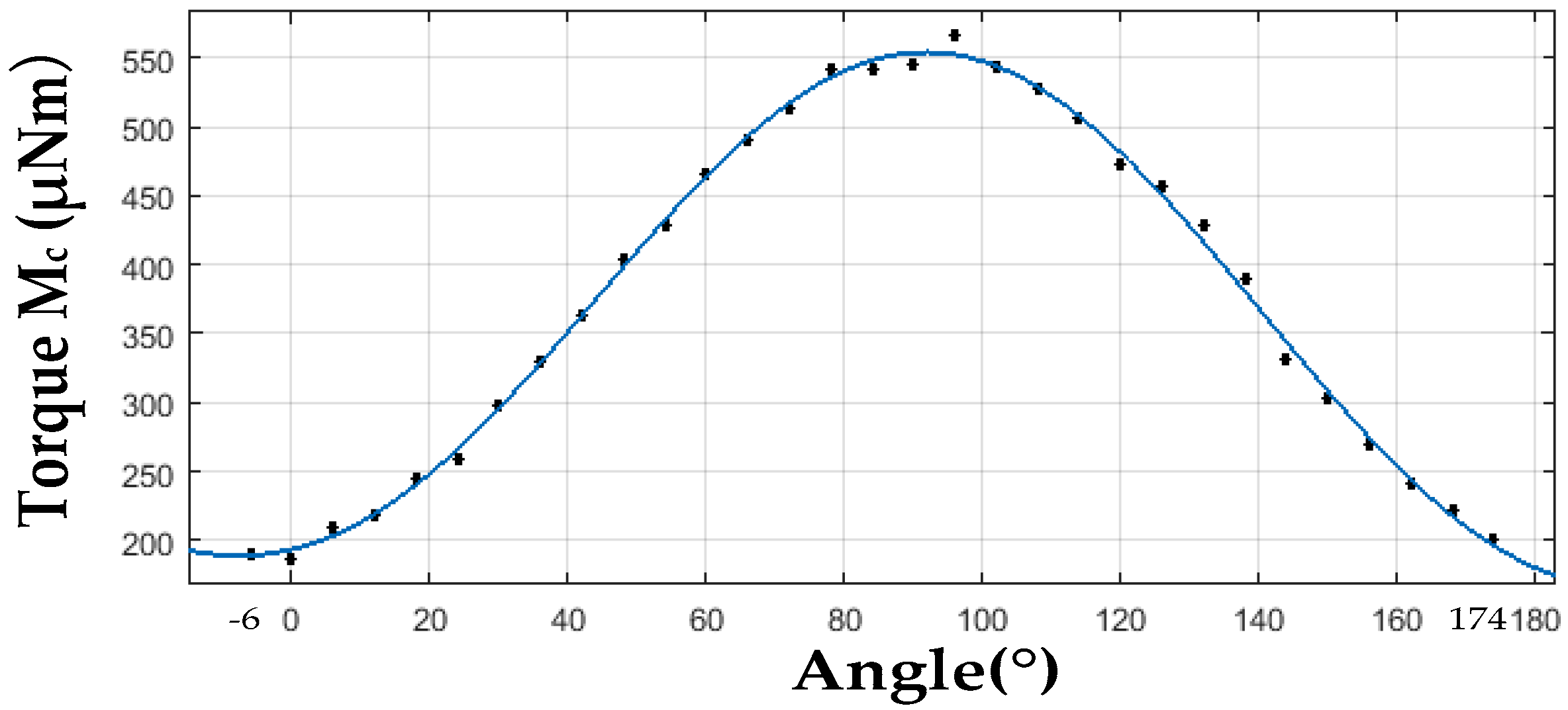
3.1. Self-Restoring Effect of Rotor
3.2. Dragging Torque of Water-Film Bearing to Spinning and Precessional Motion
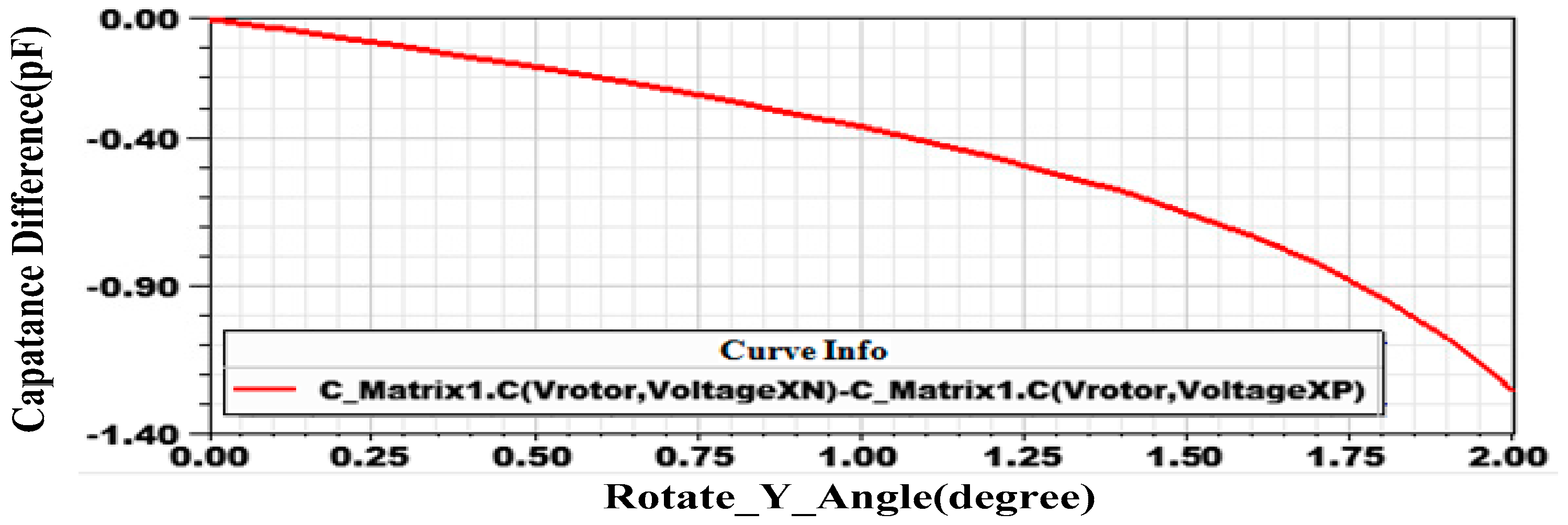
3.3. Sensing Principle
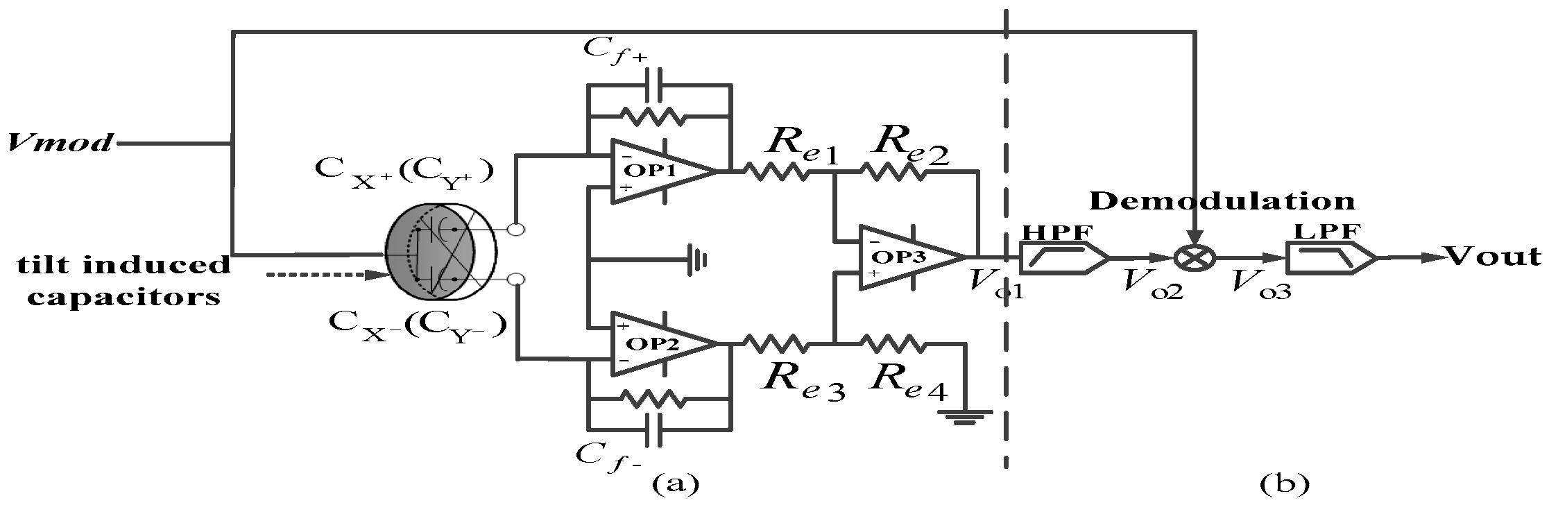
3.4. Differential Capacitance Detection and Signal Processing
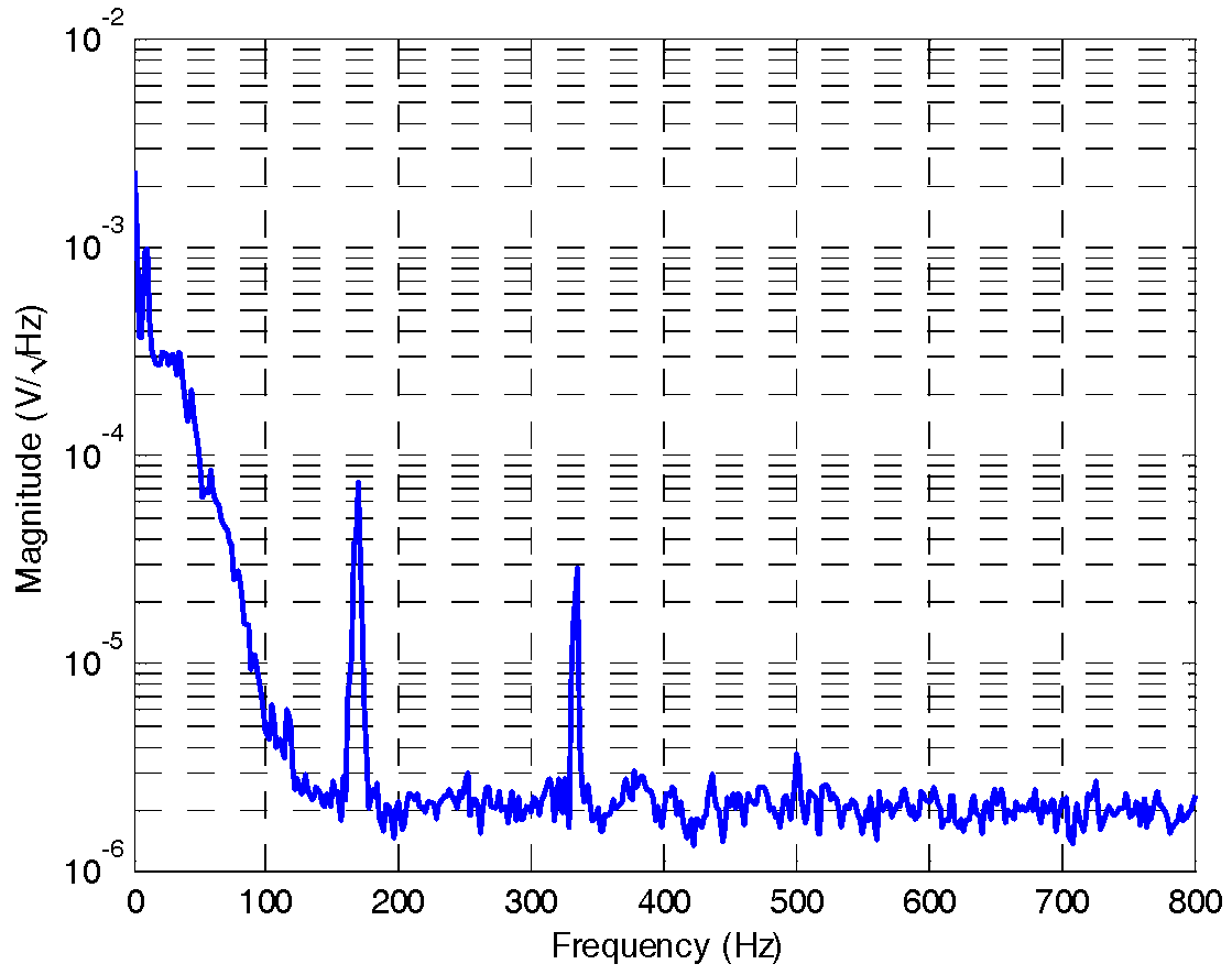
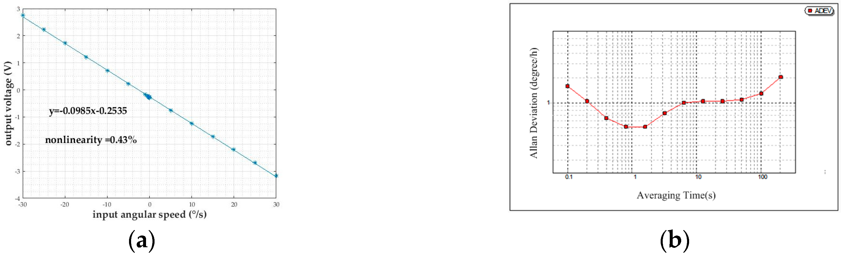
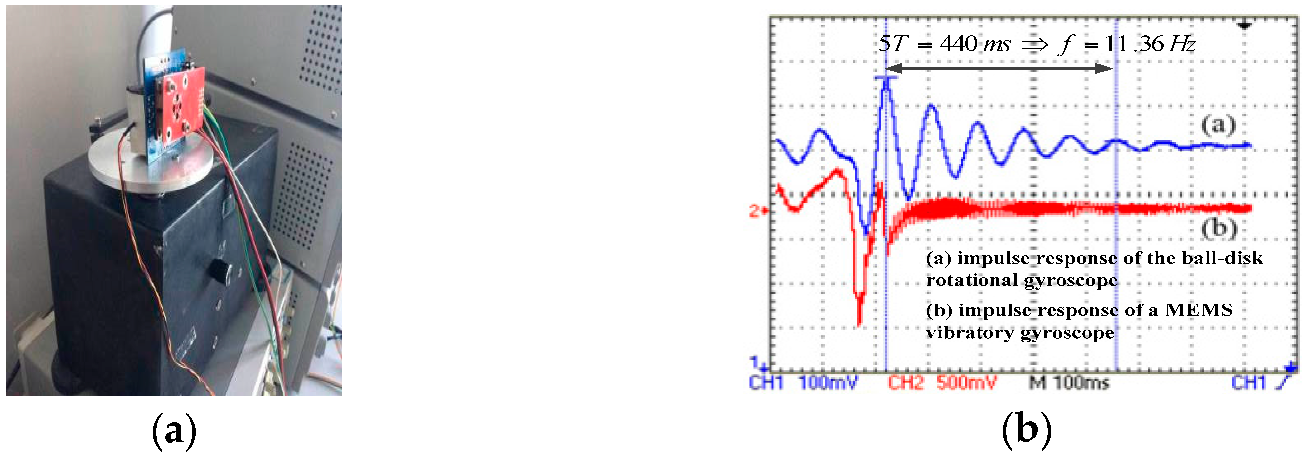
4. Measurement and Discussion
5. Conclusions
Acknowledgments
Author Contributions
Conflicts of Interest
References
- Saukoski, M.; Aaltonen, L.; Halonen, K.A.I. Zero-rate output and quadrature compensation in vibratory MEMS gyroscopes. IEEE Sens. J. 2007, 7, 1639–1651. [Google Scholar] [CrossRef]
- Elsayed, M.; Nabki, F.; Sawan, M.; El-Gamal, M. A 5 V Gyroscope with 3 aF/°/s Sensitivity, 0.6°/√hr Mechanical Noise and Drive-Sense Crosstalk Minimization. In Proceedings of the 2011 International Conference on Microelectronics (ICM), Hammamet, Tunisia, 19–22 December 2011; pp. 1–5. [Google Scholar]
- Williams, C.B.; Shearwood, C.; Mellor, P.H.; Yates, R.B. Modelling and testing of a frictionless levitated micromotor. Sens. Actuators 1997, 61, 469–473. [Google Scholar] [CrossRef]
- Shearwood, C.; Ho, K.Y.; Williams, C.B.; Gong, H. Development of a levitated micromotor for application as a gyroscope. Sens. Actuators 2000, 82, 85–92. [Google Scholar] [CrossRef]
- Zhang, W.P.; Chen, W.Y.; Zhao, X.L.; Wu, X.S.; Liu, W.; Huang, X.G.; Shao, S.Y. The study of an electromagnetic levitating micromotor for application in a rotating gyroscope. Sens. Actuators 2006, 132, 651–657. [Google Scholar] [CrossRef]
- Liu, W.; Chen, W.Y.; Zhang, W.P.; Huang, X.G.; Zhang, Z.R. Variable-capacitance micromotor with levitated diamagnetic rotor. Electron. Lett. 2008, 44, 681–683. [Google Scholar] [CrossRef]
- Liu, K.; Zhang, W.P.; Liu, W.; Chen, W.Y.; Li, K.; Cui, F.; Li, S.P. An innovative micro-diamagnetic levitation system with coils applied in micro-gyroscope. Microsyst. Technol. 2010, 16, 431–439. [Google Scholar] [CrossRef]
- Dauwalter, C.R.; Ha, J.C. A high performance magnetically suspended MEMS spinning wheel gyroscope. In Proceedings of the PLANS 2004—Position Location and Navigation Symposium, Monterey, CA, USA, 26–29 April 2004; pp. 70–77. [Google Scholar]
- Dauwalter, C.R.; Ha, J.C. Magnetically suspended MEMS spinning wheel gyroscope. IEEE Aerosp. Electron. Syst. Mag. 2005, 20, 21–26. [Google Scholar] [CrossRef]
- Tang, J.; Xiang, B.; Zhang, Y. Dynamic characteristics of the rotor in a magnetically suspended control moment gyroscope with active magnetic bearing and passive magnetic bearing. ISA Trans. 2014, 53, 1357–1365. [Google Scholar] [CrossRef] [PubMed]
- Torti, R.; Gondhalekar, V.; Tran, H.; Selfors, B.; Bart, S.; Maxwell, B. Electrostatically suspended and sensed micromechanical rate gyroscope. In Proceedings of the SPIE’s International Symposium on Optical Engineering and Photonics in Aerospace Sensing, Orlando, FL, USA, 13 July 1994; pp. 27–38. [Google Scholar]
- Esashi, M. Saving energy and natural resource by micro-nanomachining. In Proceedings of the Fifteenth IEEE International Conference on Micro Electro Mechanical Systems, Las Vegas, NV, USA, 24 January 2002; pp. 220–227. [Google Scholar]
- Murakoshi, T.; Endo, Y.; Fukatsu, K.; Nakamura, S.; Esashi, M. Electrostatically levitated ring-shaped rotational gyroscope/accelerometer. Jpn. J. Appl. Phys. 2003, 42, 2468–2472. [Google Scholar] [CrossRef]
- Nakamura, S. MEMS inertial sensor toward higher accuracy & multi-axis sensing. In Proceedings of the 2005 IEEE Sensors, Irvine, CA, USA, 30 October–3 November 2005; pp. 939–942. [Google Scholar]
- Kraft, M.; Evans, A. System level simulation of an electrostatically levitated disk. In Proceedings of the 2000 International Conference on Modeling and Simulation of Microsystems, San Diego, CA, USA, 27–29 March 2000; pp. 27–29. [Google Scholar]
- Kraft, M.; Farooqui, M.M.; Evans, A.G.R. Modelling and design of an electrostatically levitated disk for inertial sensing applications. J. Micromech. Microeng. 2001, 11, 423–427. [Google Scholar] [CrossRef]
- Gindila, M.V.; Kraft, M. Electronic interface design for an electrically floating micro-disk. J. Micromech. Microeng. 2003, 13, S11–S16. [Google Scholar] [CrossRef]
- Kukharenka, E.; Farooqui, M.M.; Grigore, L.; Kraft, M.; Hollinshead, N. Electroplating moulds using dry film thick negative photoresist. J. Micromech. Microeng. 2003, 13, 95–98. [Google Scholar] [CrossRef]
- Damrongsak, B.; Kraft, M. A micromachined electrostatically suspended gyroscope with digital force feedback. In Proceedings of the 2005 IEEE Sensors, Irvine, CA, USA, 30 October–3 November 2005; pp. 401–404. [Google Scholar]
- Damrongsak, B. Design and simulation of a micromachined electrostatically suspended gyroscope. In Proceedings of the Seminar on MEMS Sensors and Actuators, London, UK, 28 April 2006; pp. 267–272. [Google Scholar]
- Xia, D.Z.; Chen, S.L.; Wang, S.R. Development of a prototype miniature silicon microgyroscope. Sensors 2009, 9, 4586–4605. [Google Scholar] [CrossRef] [PubMed]
- Loveday, P.W.; Rogers, C.A. The influence of control system design on the performance of vibratory gyroscopes. J. Sound Vib. 2002, 255, 417–432. [Google Scholar] [CrossRef]
- Cui, J.; Guo, Z.Y.; Zhao, Q.C.; Yang, Z.C. Force rebalance controller synthesis for a micromachined vibratory gyroscope based on sensitivity margin specifications. J. Microelectromech. Syst. 2011, 20, 1382–1394. [Google Scholar] [CrossRef]
- Yoxall, B.E.; Chan, M.; Harake, R.S.; Pan, T.; Horsley, D.A. Rotary Liquid Droplet Microbearing. J. Microelectromech. Syst. 2012, 21, 721–729. [Google Scholar] [CrossRef]
- Sun, G.; Liu, T.; Sen, P.; Shen, W.; Gudeman, C.; Kim, C. Electrostatic side-drive rotary stage on liquid-ring bearing. J. Microelectromech. Syst. 2014, 23, 147–156. [Google Scholar] [CrossRef]
- Takei, A.; Matsumoto, K.; Shomoyama, I. Capillary motor driven by electrowetting. Lab Chip 2010, 10, 1781–1786. [Google Scholar] [CrossRef] [PubMed]
- Kulik, V.M.; Semenov, B.N.; Boiko, A.V.; Seoudi, B.M.; Chun, H.H.; Lee, I. Measurement of dynamic properties of viscoelastic materials. Exp. Mech. 2009, 49, 417–425. [Google Scholar] [CrossRef]
- Keyes, D.; Abernathy, F. A model for the dynamics of polymers in laminar shear flows. J. Fluid Mech. 1987, 185, 503–522. [Google Scholar] [CrossRef]
- Rabin, Y.; Zielinska, B.J.A. Scale-dependent enhancement and damping of vorticity disturbances by polymers in elongational flow. Phys. Rev. Lett. 1989, 63, 512–516. [Google Scholar] [CrossRef] [PubMed]
- Dubief, Y.; White, C.M.; Terrapon, V.E.; Shaqfeh, E.S.G.; Moin, P.; Lele, S.K. On the coherent drag-reducing and turbulence-enhancing behaviour of polymers in wall flows. J. Fluid Mech. 2004, 514, 271–280. [Google Scholar] [CrossRef]
- Chen, D.; Liu, X.; Zhang, H.; Li, H.; Weng, R.; Li, L.; Zhang, Z. Friction reduction for a rotational gyroscope with mechanical support by fabrication of a biomimetic superhydrophobic surface on a ball-disk shaped rotor and the application of a water film bearing. Micromachines 2017, 8, 223. [Google Scholar] [CrossRef]
- Spikes, H.; Granick, S. Equation for slip of simple liquids at smooth solid surface. Langmuir 2003, 19, 5065–5071. [Google Scholar] [CrossRef]
- Li, H.; Liu, X.; Weng, R.; Zhang, H. Micro-Angle Tilt Detection for the Rotor of a Novel Rotational Gyroscope with 0.47’’ Resolution. Front. Inf. Technol. Electron. Eng. 2016, 18, 591–598. [Google Scholar] [CrossRef]


© 2018 by the authors. Licensee MDPI, Basel, Switzerland. This article is an open access article distributed under the terms and conditions of the Creative Commons Attribution (CC BY) license (http://creativecommons.org/licenses/by/4.0/).
Share and Cite
Chen, D.; Liu, X.; Zhang, H.; Li, H.; Weng, R.; Li, L.; Rong, W.; Zhang, Z. A Rotational Gyroscope with a Water-Film Bearing Based on Magnetic Self-Restoring Effect. Sensors 2018, 18, 415. https://doi.org/10.3390/s18020415
Chen D, Liu X, Zhang H, Li H, Weng R, Li L, Rong W, Zhang Z. A Rotational Gyroscope with a Water-Film Bearing Based on Magnetic Self-Restoring Effect. Sensors. 2018; 18(2):415. https://doi.org/10.3390/s18020415
Chicago/Turabian StyleChen, Dianzhong, Xiaowei Liu, Haifeng Zhang, Hai Li, Rui Weng, Ling Li, Wanting Rong, and Zhongzhao Zhang. 2018. "A Rotational Gyroscope with a Water-Film Bearing Based on Magnetic Self-Restoring Effect" Sensors 18, no. 2: 415. https://doi.org/10.3390/s18020415
APA StyleChen, D., Liu, X., Zhang, H., Li, H., Weng, R., Li, L., Rong, W., & Zhang, Z. (2018). A Rotational Gyroscope with a Water-Film Bearing Based on Magnetic Self-Restoring Effect. Sensors, 18(2), 415. https://doi.org/10.3390/s18020415