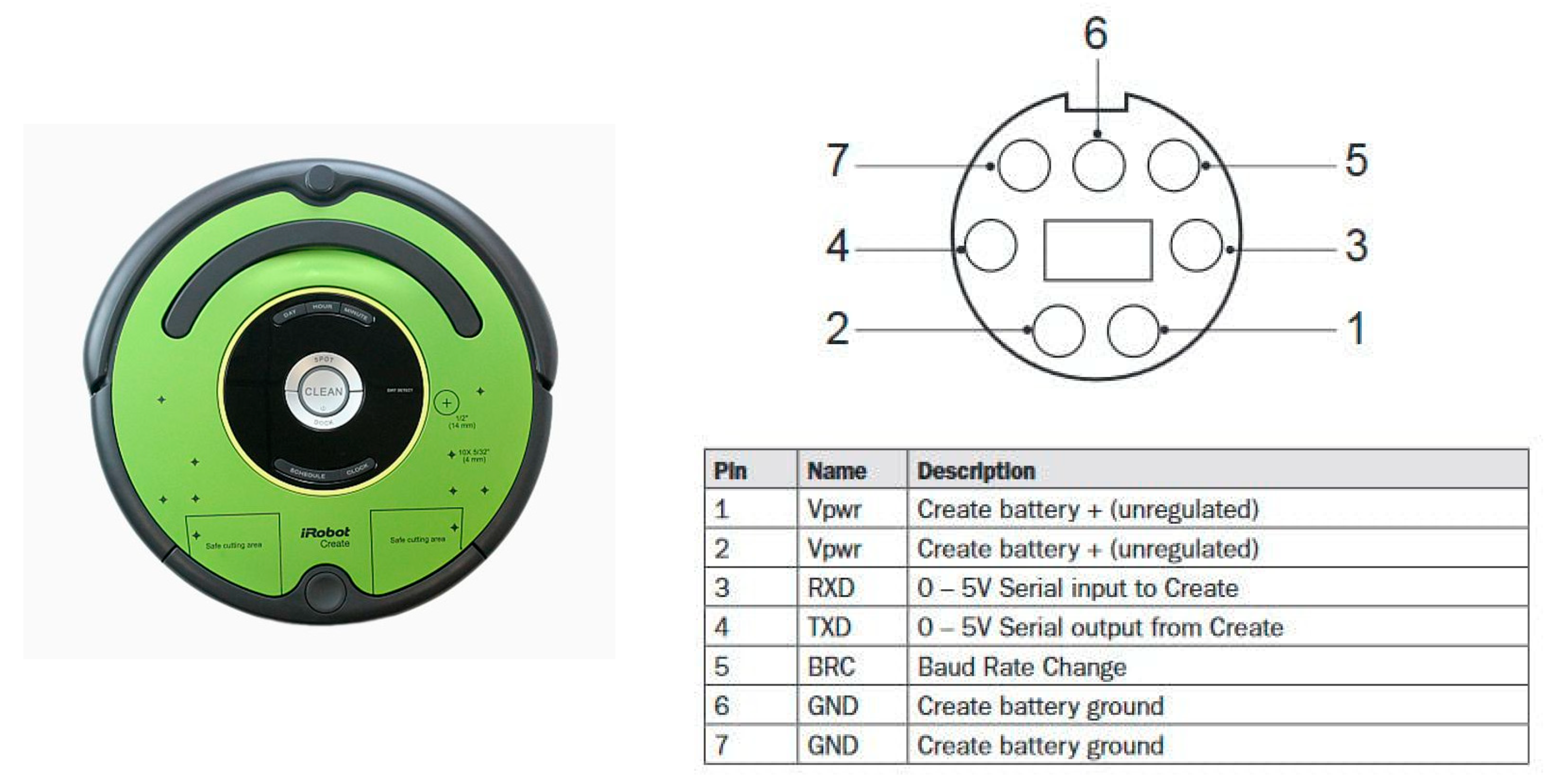
Figure 1.
IRobot Create 2.
Figure 1.
IRobot Create 2.
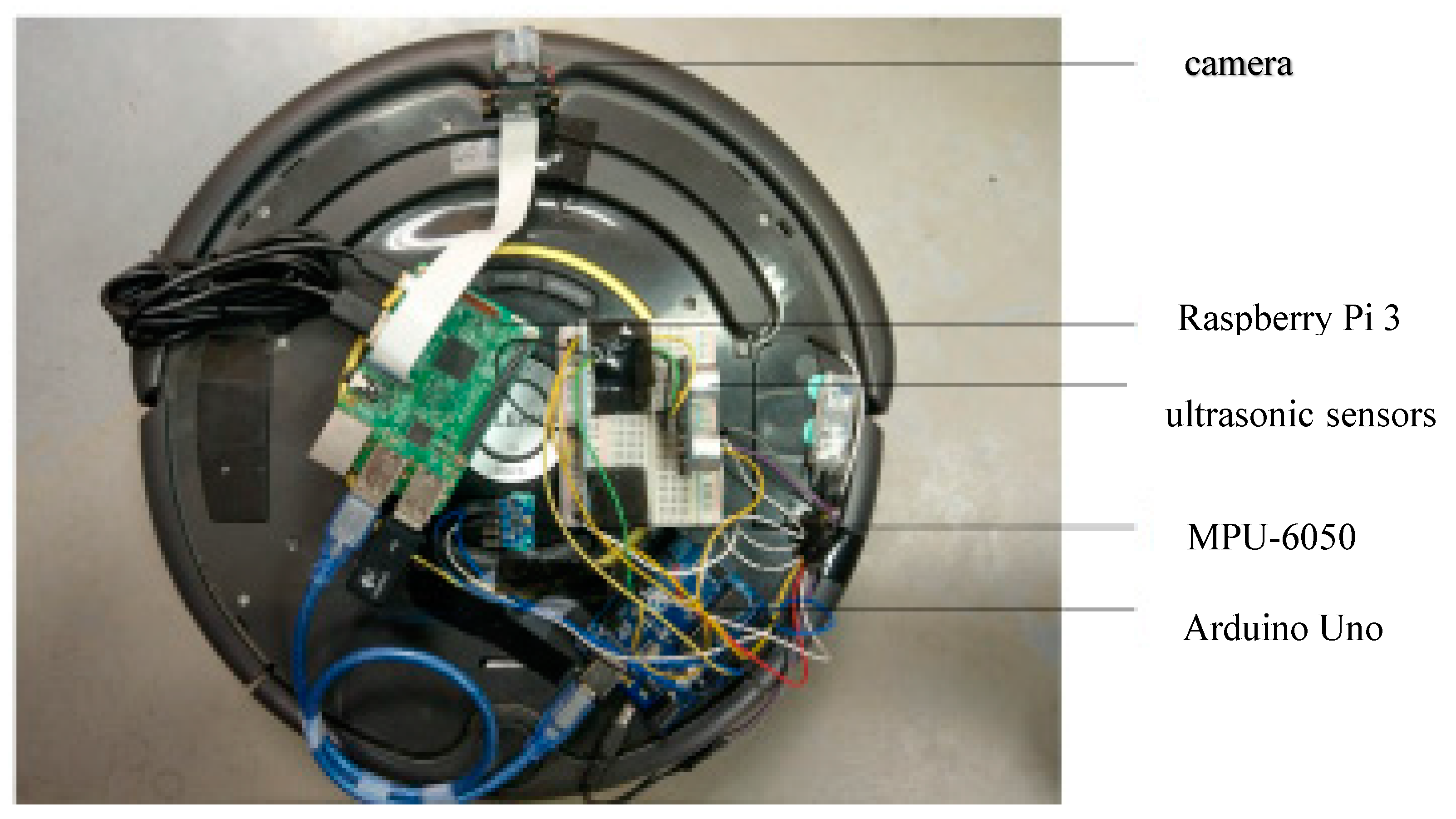
Figure 2.
Cleaning robot hardware architecture.
Figure 2.
Cleaning robot hardware architecture.
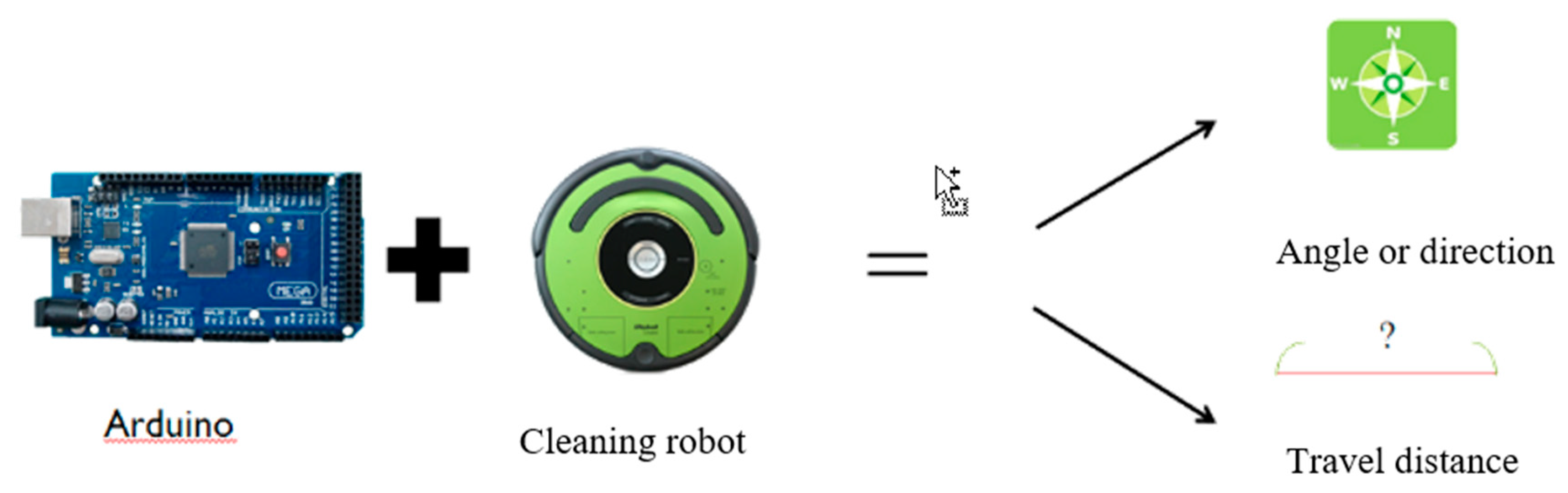
Figure 3.
Arduino is used as the platform for calculating travel distance and direction angle.
Figure 3.
Arduino is used as the platform for calculating travel distance and direction angle.
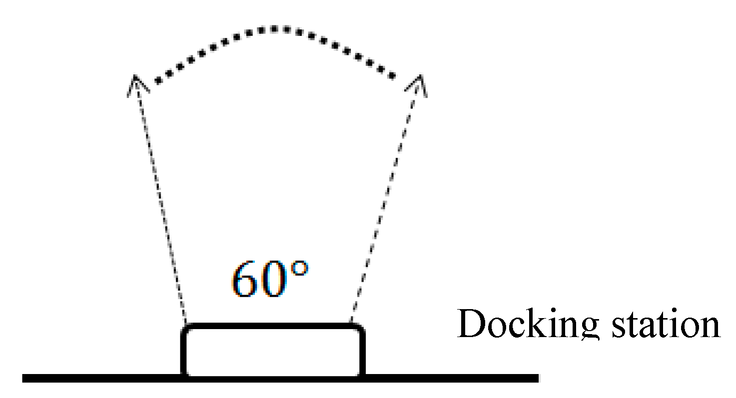
Figure 4.
Exiting range of infrared light.
Figure 4.
Exiting range of infrared light.
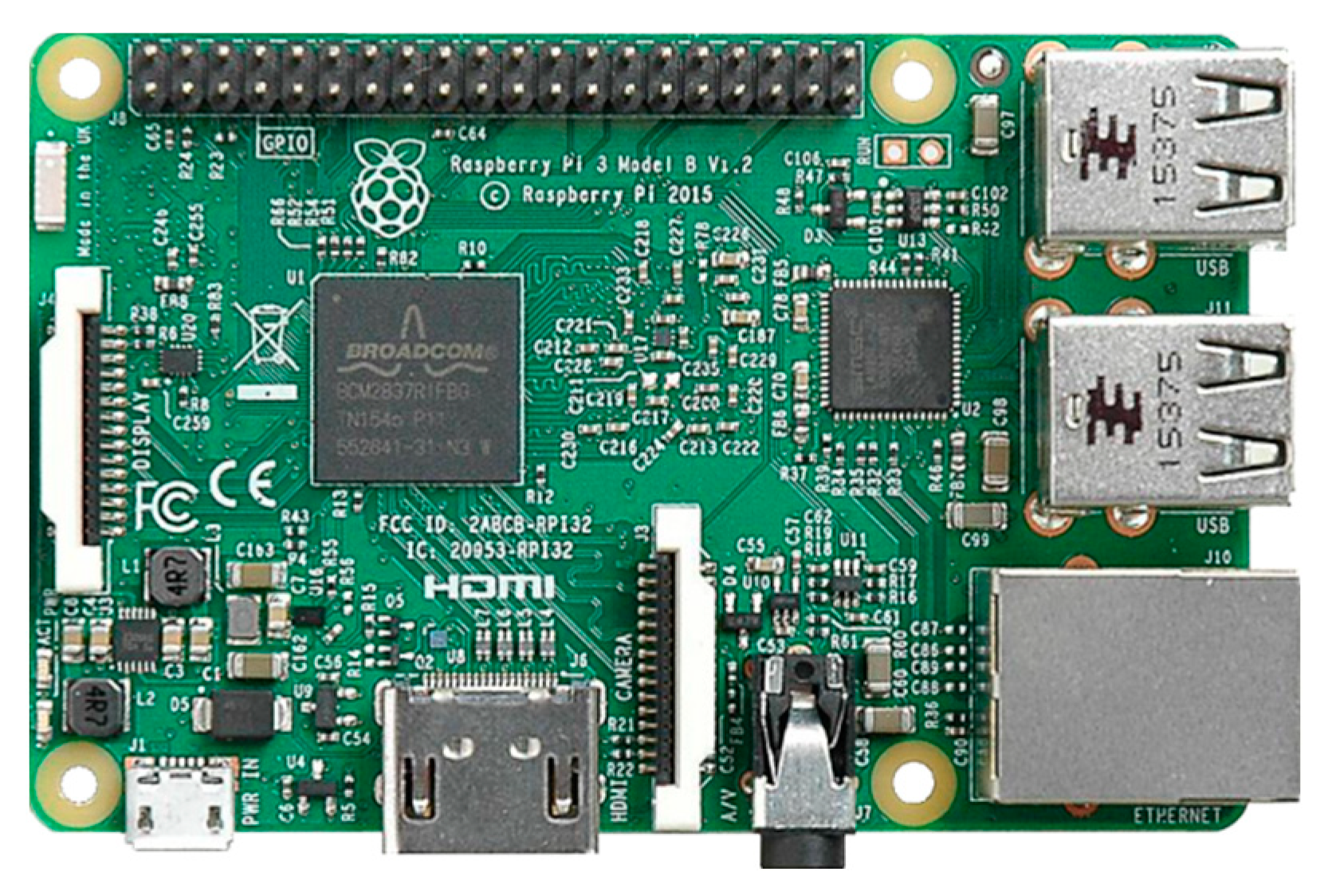
Figure 6.
Raspberry Pi 3.
Figure 6.
Raspberry Pi 3.
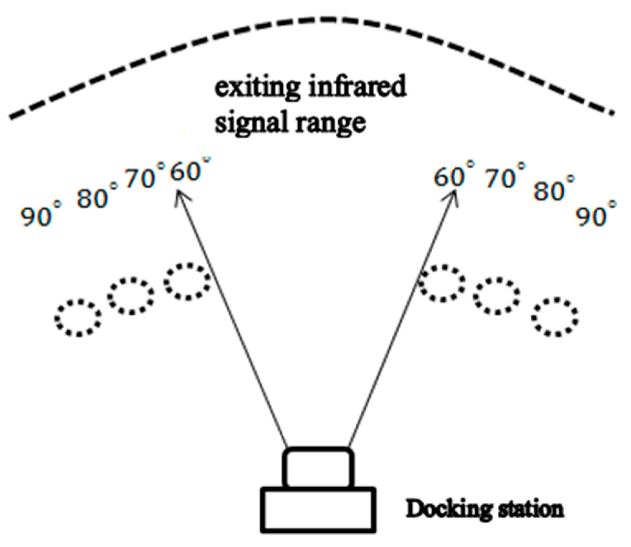
Figure 7.
Infrared signal range with and without adding three infrared LEDs.
Figure 7.
Infrared signal range with and without adding three infrared LEDs.
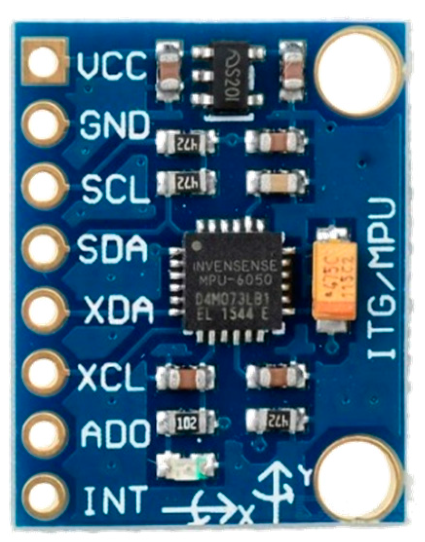
Figure 8.
MPU-6050 six-axis sensor.
Figure 8.
MPU-6050 six-axis sensor.
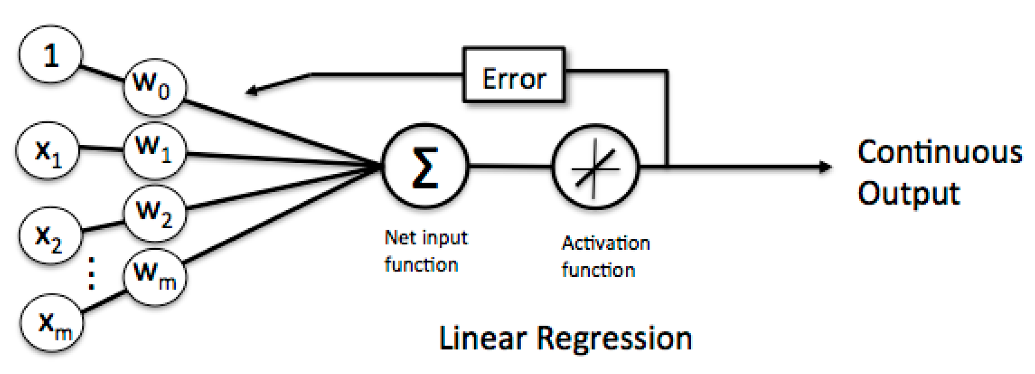
Figure 9.
Machine learning-linear regression.
Figure 9.
Machine learning-linear regression.
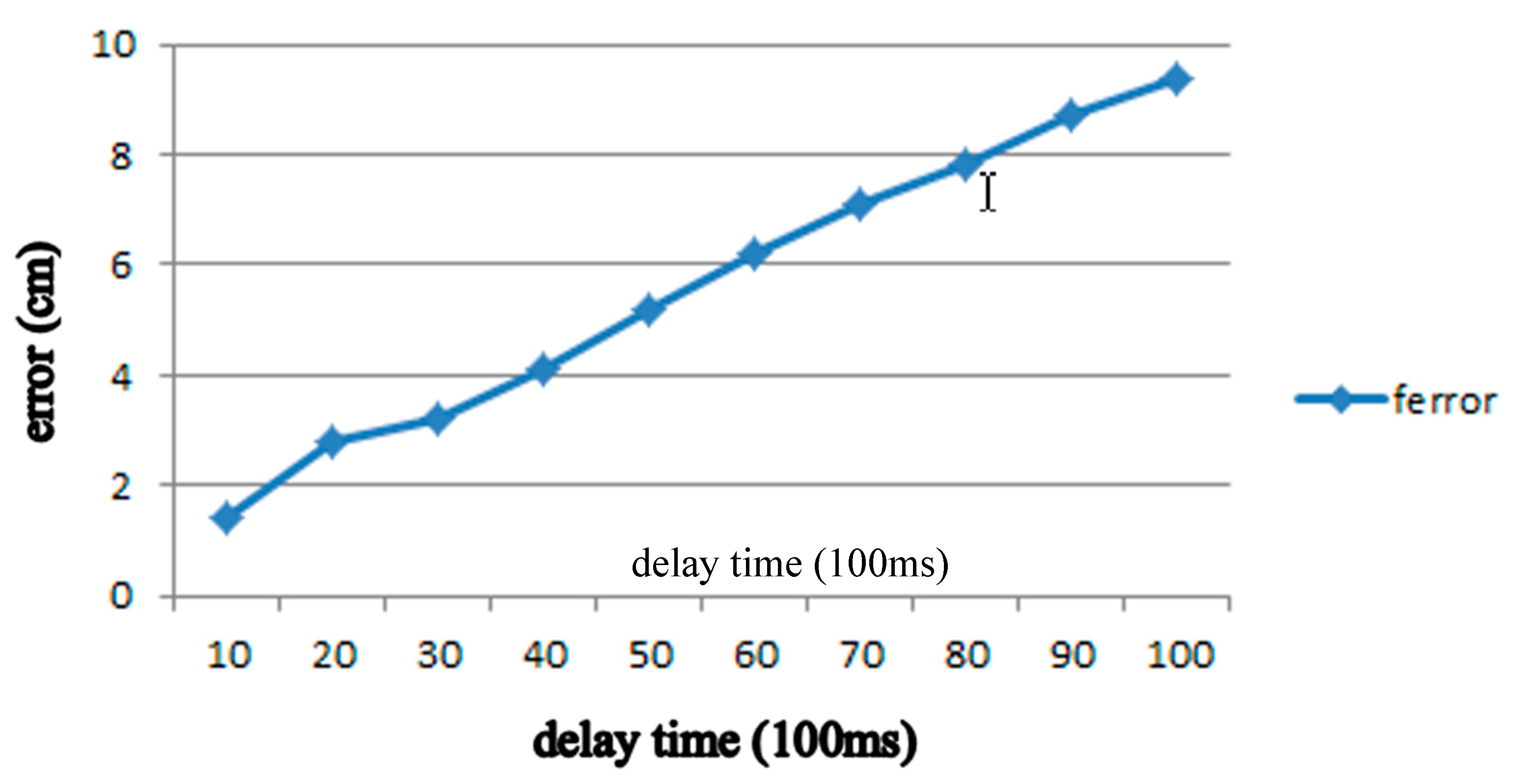
Figure 10.
curve.
Figure 10.
curve.
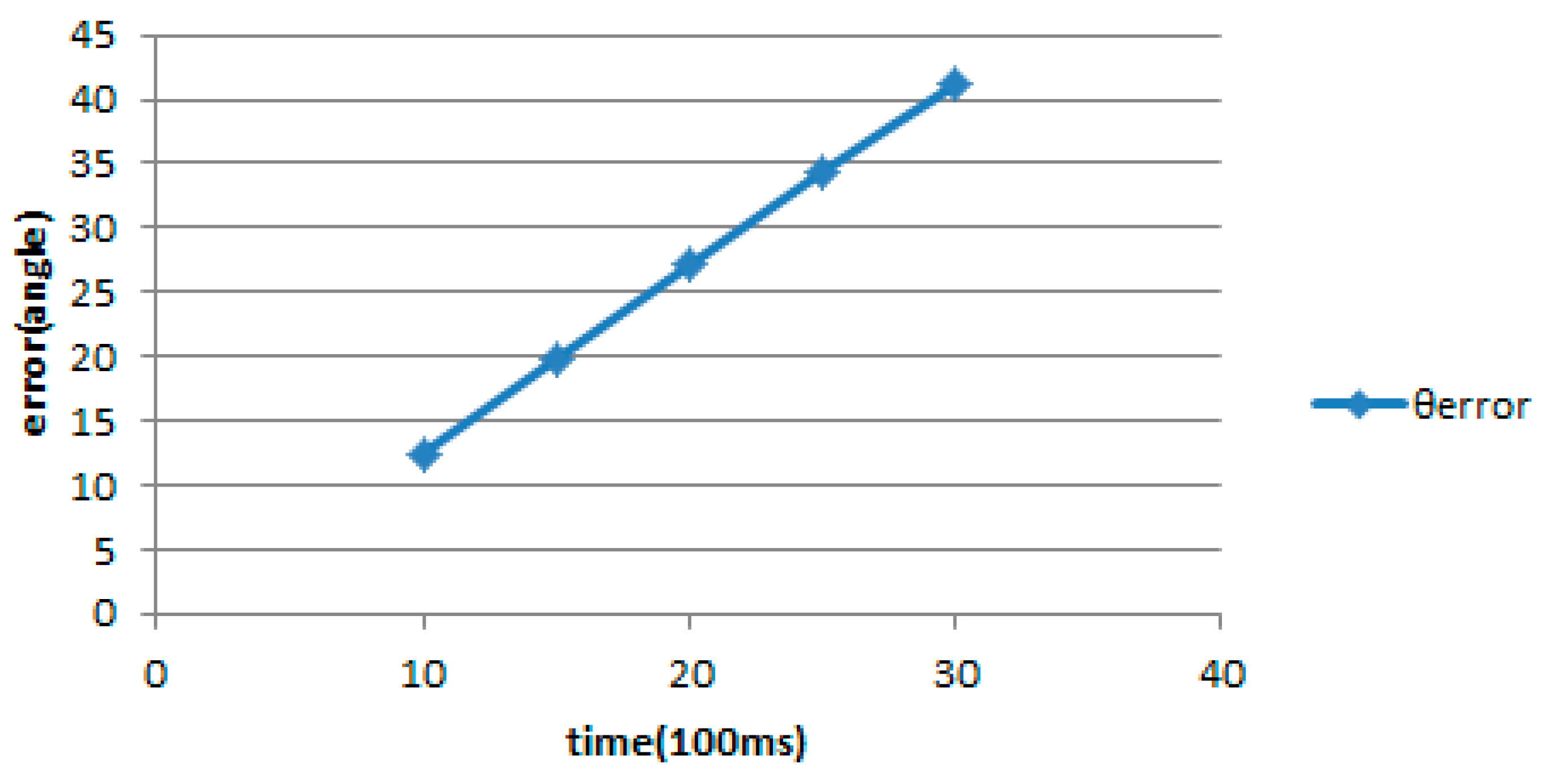
Figure 11.
Graph.
Figure 11.
Graph.
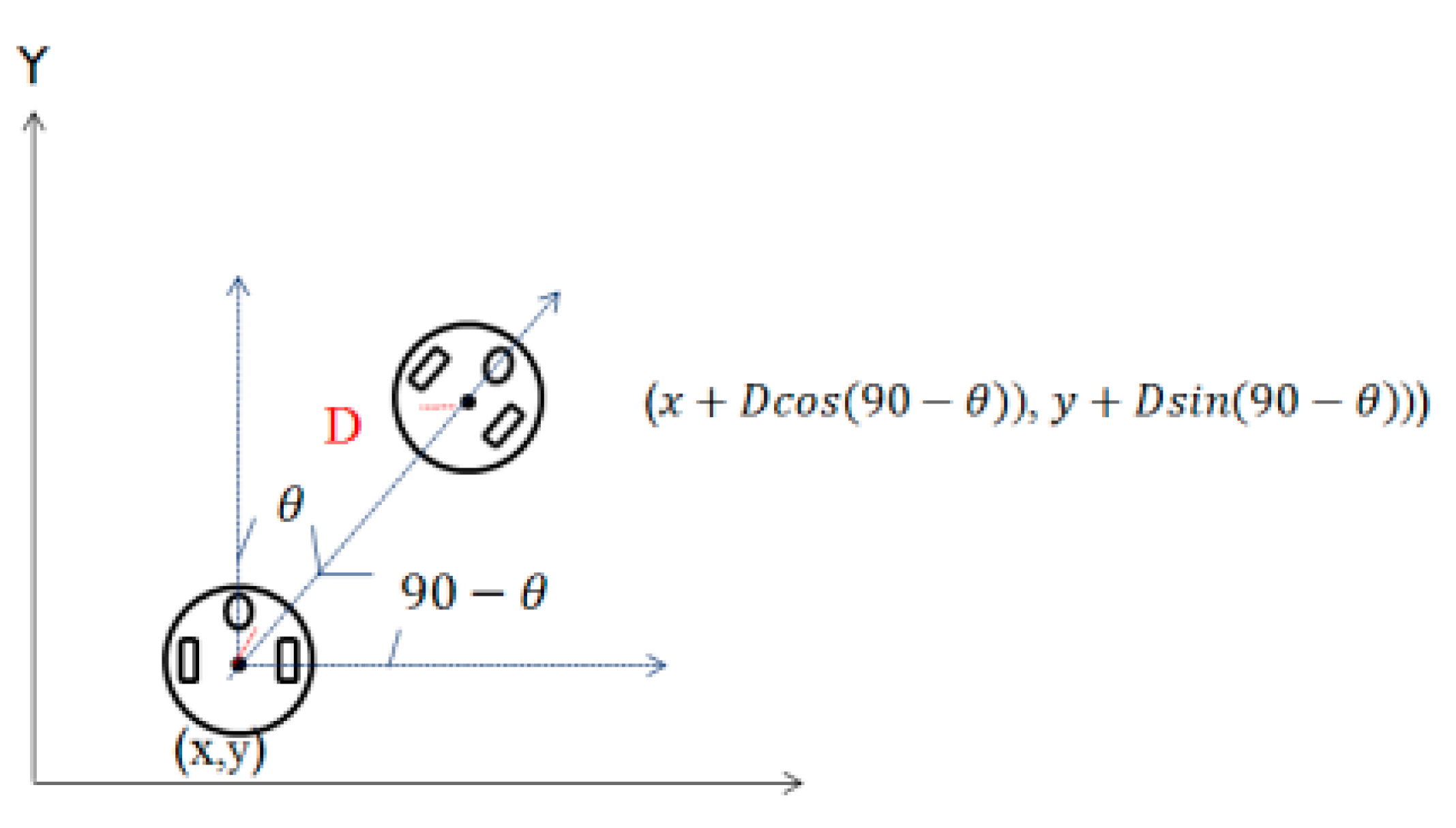
Figure 12.
Robot position estimation.
Figure 12.
Robot position estimation.
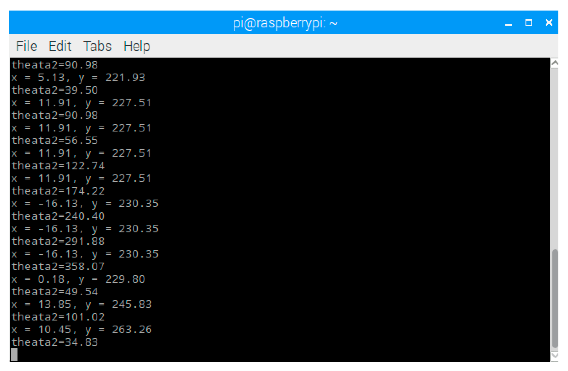
Figure 13.
Remote observation interface.
Figure 13.
Remote observation interface.
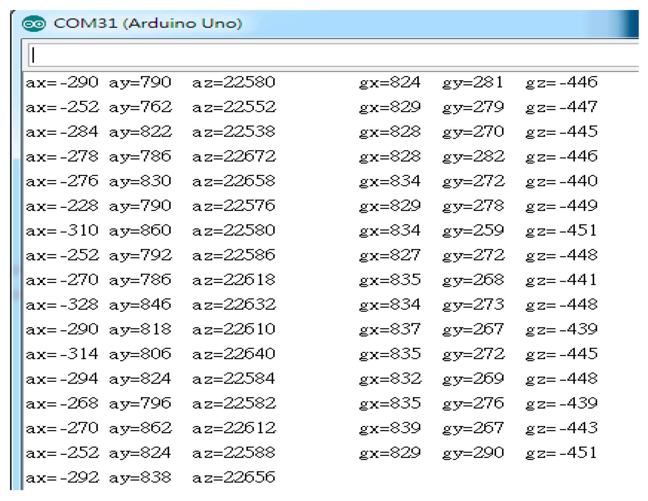
Figure 14.
Six-axis sensor raw value.
Figure 14.
Six-axis sensor raw value.
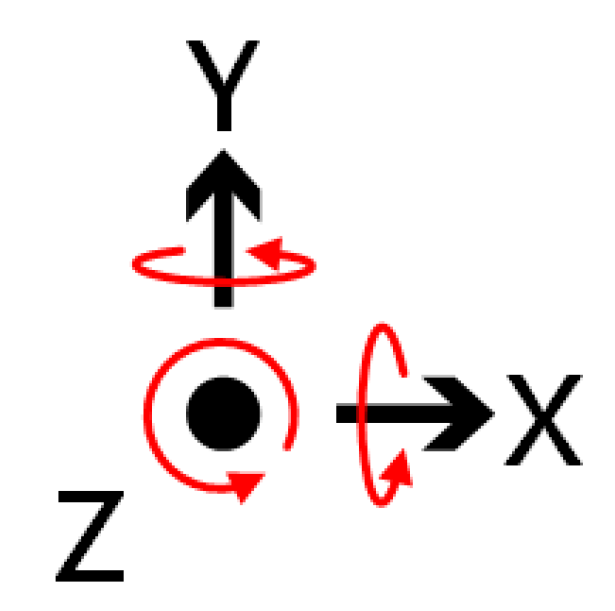
Figure 15.
Gyro rotation direction diagram.
Figure 15.
Gyro rotation direction diagram.
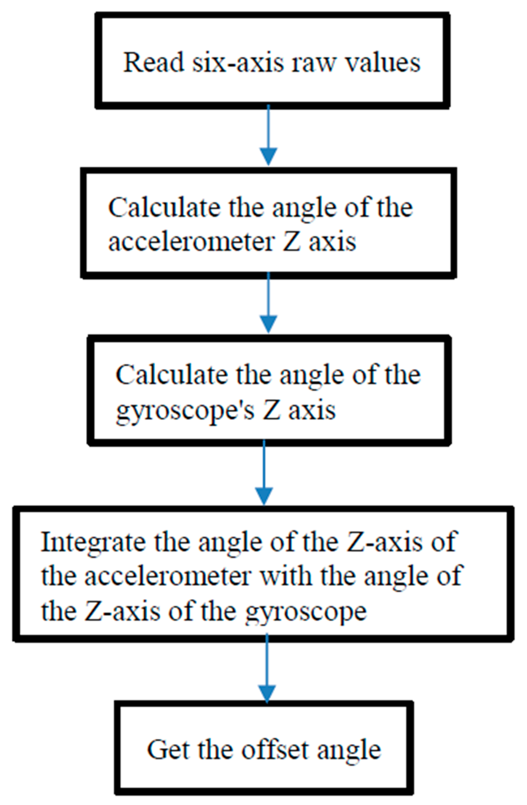
Figure 16.
Operation flowchart of six-axis sensors.
Figure 16.
Operation flowchart of six-axis sensors.
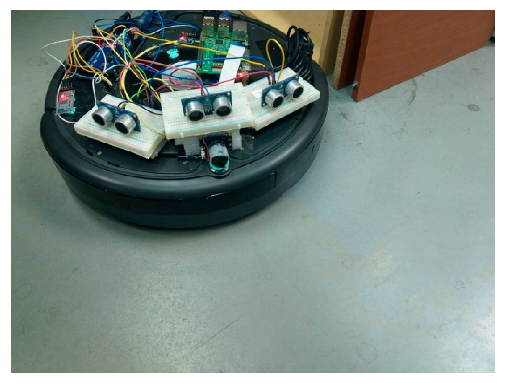
Figure 17.
Three ultrasonic sensors installed on the clean robot.
Figure 17.
Three ultrasonic sensors installed on the clean robot.
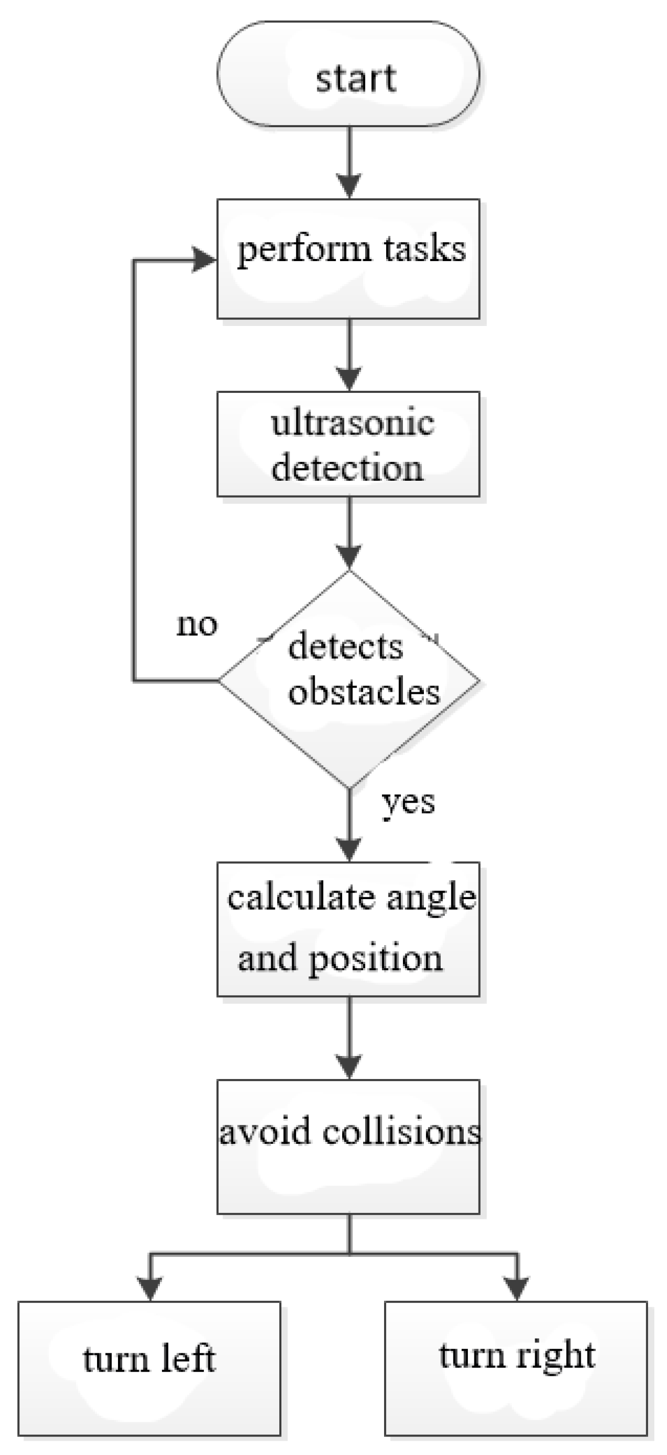
Figure 18.
Operation flowchart of ultrasonic sensors.
Figure 18.
Operation flowchart of ultrasonic sensors.
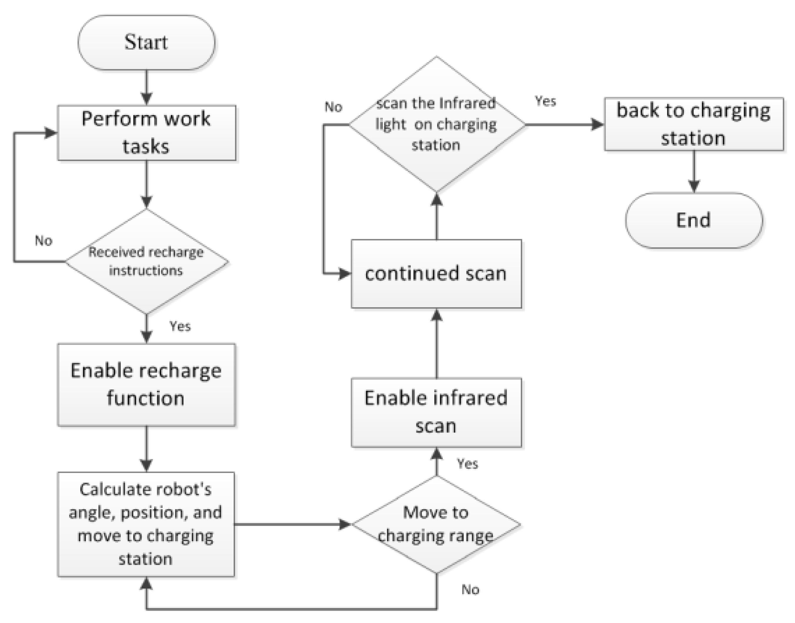
Figure 19.
Auto-recharging mechanism for cleaning robot.
Figure 19.
Auto-recharging mechanism for cleaning robot.
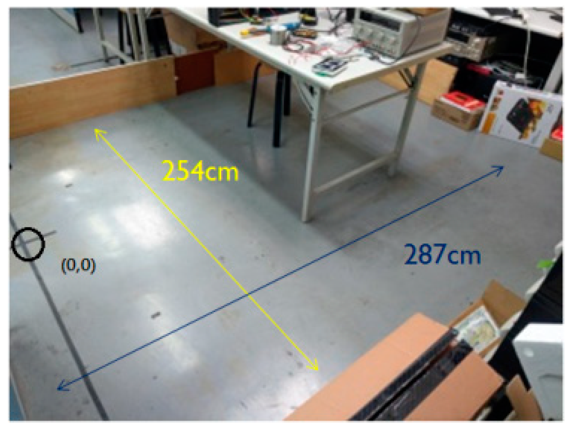
Figure 20.
Experimental environment.
Figure 20.
Experimental environment.
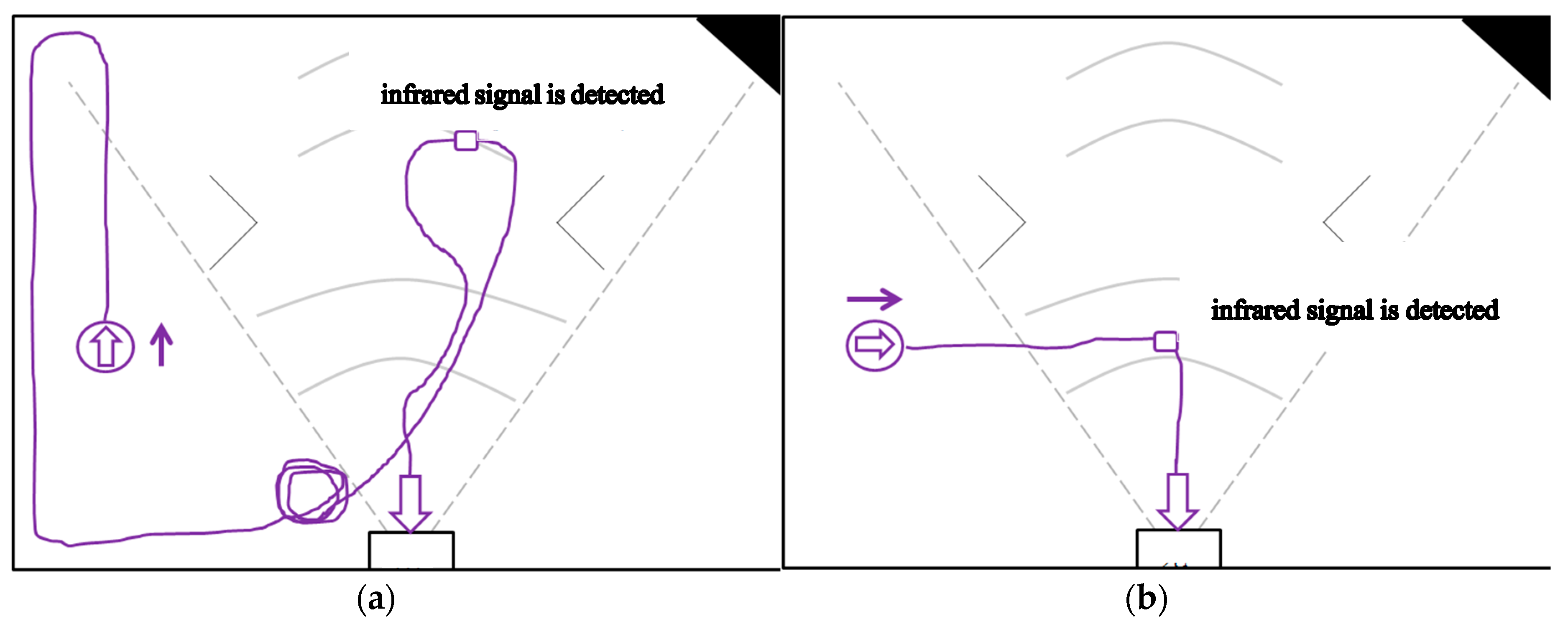
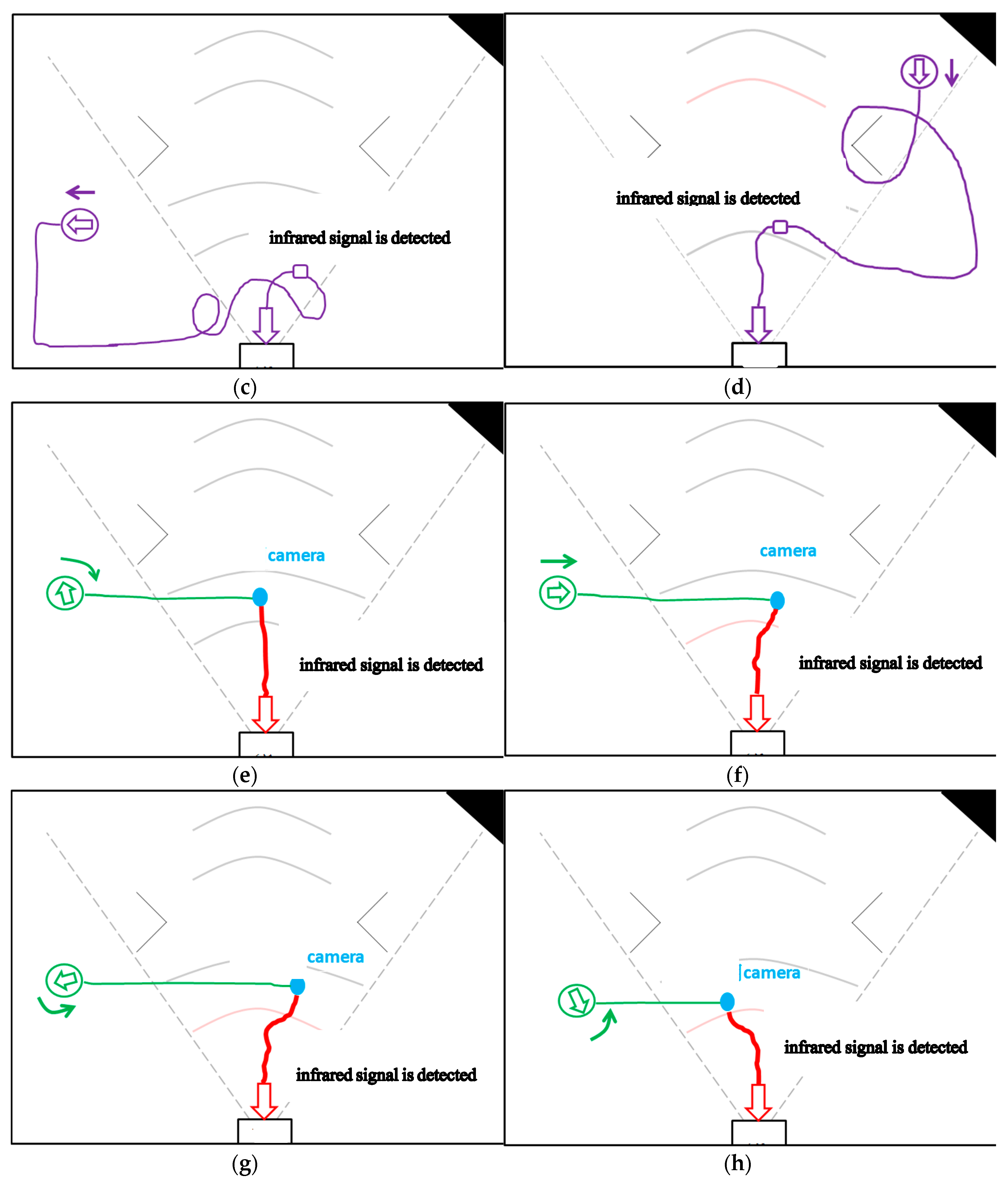
Figure 21.
First part of experiment: the cleaning robot is placed outside the range of the infrared signal emitted by the infrared sensor of the docking station to back to charging by general-type and the proposed mechanisms. (a)Without detecting the infrared signal in the general-type mechanism, robot facing up bypasses until the infrared signal is detected. (b) Without detecting the infrared signal in the general-type mechanism, robot facing the right did not bypasses until the infrared signal is detected. (c) Without detecting the infrared signal in the general-type mechanism, robot facing the left bypasses until the infrared signal is detected. (d) Without detecting the infrared signal in the general-type mechanism, facing down bypasses until the infrared signal is detected. (e) By the proposed mechanism, robot facing up determines which direction should be followed and then finishes the recharge action. (f) By the proposed mechanism, robot facing the right determines which direction should be followed and then finishes the recharge action. (g) By the proposed mechanism, robot facing the left determines which direction should be followed and then finishes the recharge action. (h) By the proposed mechanism, robot facing down determines which direction should be followed and then finishes the recharge action.


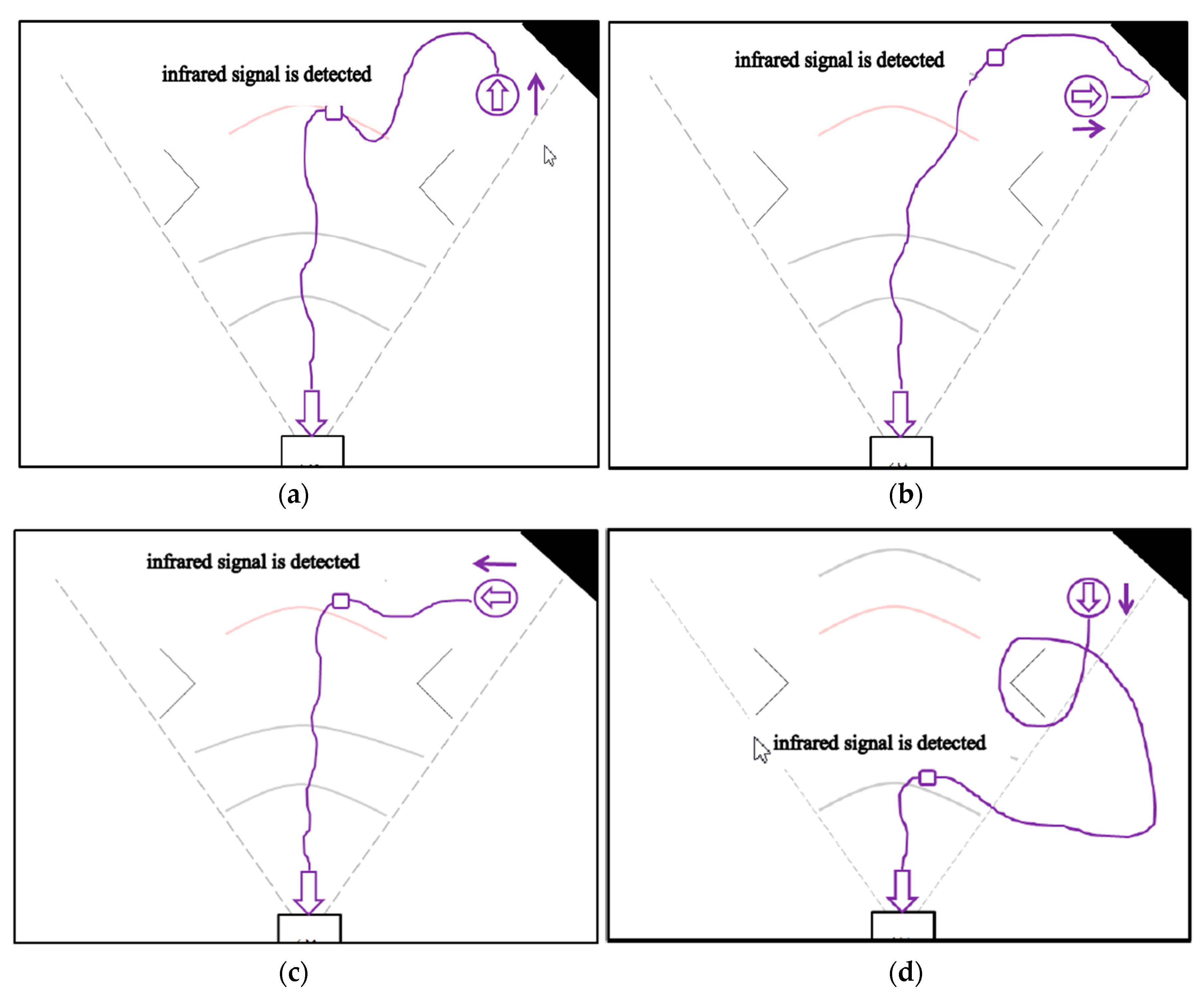
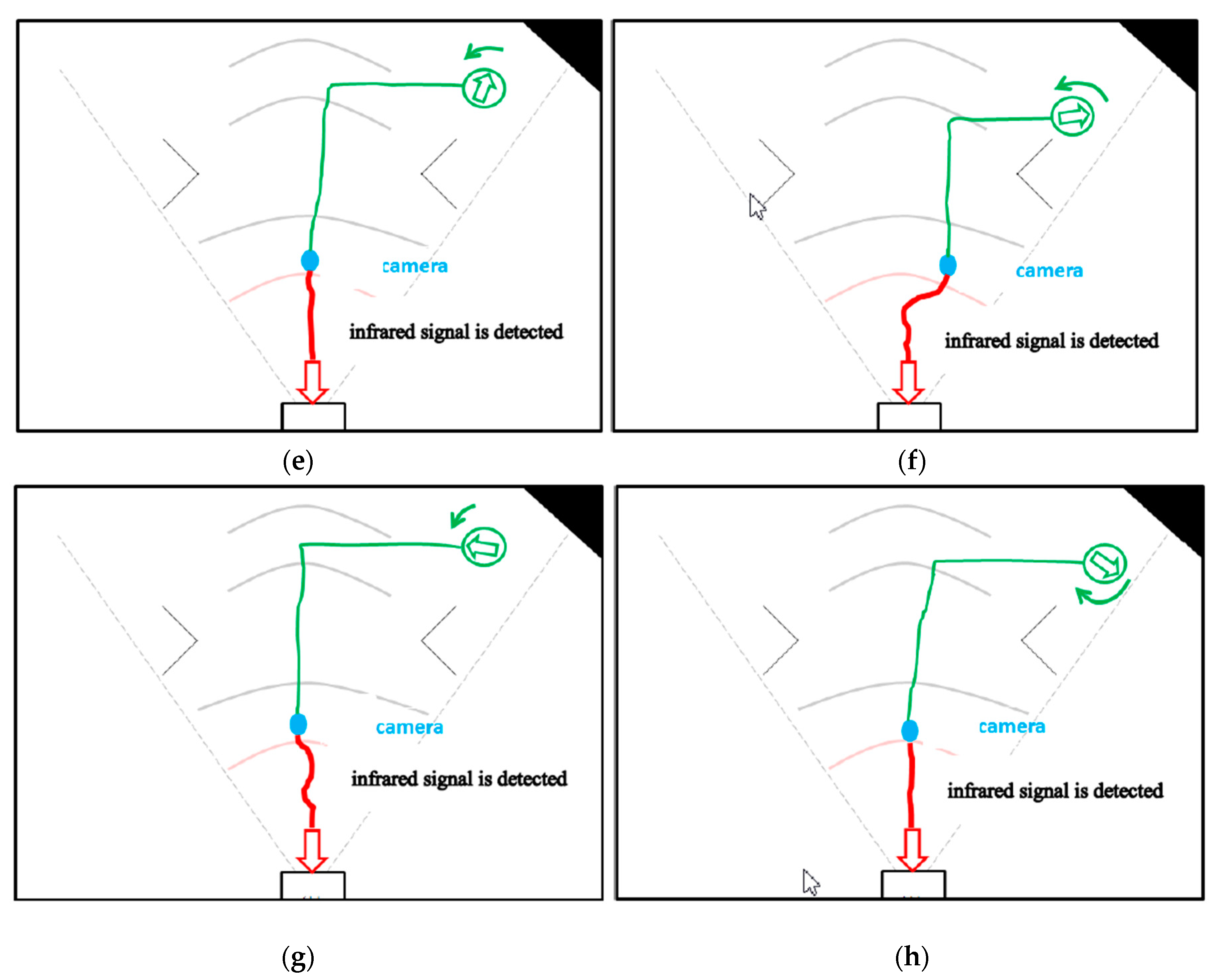
Figure 22.
Second part of experiment: the cleaning robot is placed inside the range of the infrared signal emitted by the infrared sensor of the docking station to back to charging by general-type and the proposed mechanisms. (a) In the general-type mechanism, robot facing up bypasses until the infrared signal is detected. (b) In the general-type mechanism, robot facing the right bypasses until the infrared signal is detected. (c) In the general-type mechanism, robot facing the left bypasses until the infrared signal is detected. (d) In the general-type mechanism, robot facing down bypasses until the infrared signal is detected. (e) By the proposed mechanism, robot facing up determines which direction should be followed and then finishes the recharge action. (f) By the proposed mechanism, robot facing the right determines which direction should be followed and then finishes the recharge action. (g) By the proposed mechanism, robot facing the left determines which direction should be followed and then finishes the recharge action. (h) By the proposed mechanism, robot facing the right determines which direction should be followed and then finishes the recharge action.


Table 1.
Infrared signal range with and without adding three infrared LEDs.
Table 1.
Infrared signal range with and without adding three infrared LEDs.
| | Without Adding Three Infrared LEDs | With Adding Three Infrared LEDs |
|---|
| Infrared signal range (degree) | 60 | 60–90 |
Table 2.
Specifications of MPU-6050 six-axis sensor.
Table 2.
Specifications of MPU-6050 six-axis sensor.
| Chip model | MPU-6050 |
| Power supply | 3–5 V |
| Communication protocol | I2C |
| Gyroscope range | , |
| Accelerometer range | , , , g |
| 16-bit AD converter/16-bit data output |
Table 3.
Travel Distance—General Estimation.
Table 3.
Travel Distance—General Estimation.
| Travel Time (s) | Estimated Travel Distance (cm) | Actual Travel Distance (cm) | Distance Error (cm) |
|---|
| 10 | 5 | 6.45 | 1.45 |
| 20 | 10 | 12.8 | 2.8 |
| 30 | 15 | 18.2 | 3.2 |
| 40 | 20 | 24.1 | 4.1 |
| 50 | 25 | 30.2 | 5.2 |
| 60 | 30 | 36.2 | 6.2 |
| 70 | 35 | 42.1 | 7.1 |
| 80 | 40 | 47.8 | 7.8 |
| 90 | 45 | 53.7 | 8.7 |
| 100 | 50 | 59.4 | 9.4 |
Table 4.
Comparison of travel distance after compensation.
Table 4.
Comparison of travel distance after compensation.
| Travel Time (s) | Estimated Travel Distance (cm) | Actual Travel Distance (cm) | Distance Error (cm) |
|---|
| 10 | 6 | 5.9 | −0.1 |
| 20 | 12 | 11.8 | −0.2 |
| 30 | 18 | 18.2 | 0.2 |
| 40 | 23.97 | 24.2 | 0.23 |
| 50 | 29.95 | 30.1 | 0.15 |
| 60 | 35.93 | 36.3 | 0.37 |
| 70 | 41.92 | 42.4 | 0.48 |
| 80 | 47.9 | 48.6 | 0.7 |
| 90 | 53.88 | 54.3 | 0.42 |
| 100 | 59.86 | 60.4 | 0.54 |
| 120 | 71.63 | 71.4 | −0.23 |
| 140 | 83.57 | 83.5 | −0.07 |
| 160 | 95.51 | 96.2 | 0.69 |
| 200 | 119.39 | 118.5 | −0.89 |
| 250 | 149.23 | 146 | −3.23 |
| 300 | 179.08 | 175.8 | −3.28 |
| 400 | 238.77 | 231.7 | −7.07 |
Table 5.
Rotation angle calculation—general estimation method.
Table 5.
Rotation angle calculation—general estimation method.
| Rotation Time (s) | Estimated Rotation Angle (°) | Actual Rotation Angle (°) | Angle Error (°) |
|---|
| 1 | 42 | 29.5 | 12.5 |
| 1.5 | 63.825 | 44 | 19.825 |
| 2 | 85.1 | 58 | 27.1 |
| 2.5 | 106.375 | 72 | 34.375 |
| 3 | 127.65 | 86.5 | 41.15 |
Table 6.
Comparison of rotation angle after compensation.
Table 6.
Comparison of rotation angle after compensation.
| Rotation Time (s) | Estimated Rotation Angle (°) | Actual Rotation Angle (°) | Angle Error (°) |
|---|
| 10 | 29.49 | 29 | 0.49 |
| 15 | 44.025 | 44 | 0.025 |
| 20 | 58.01 | 59 | 0.99 |
| 25 | 71.985 | 72 | 0.015 |
| 30 | 85.97 | 86.5 | 0.53 |
| 35 | 100.895 | 101.5 | 0.6 |
| 40 | 113.09 | 114 | 0.91 |
| 45 | 129.675 | 127.5 | −2.175 |
| 50 | 144.07 | 142.3 | −1.77 |
| 55 | 158.465 | 157.5 | −0.965 |
Table 7.
Distance table.
| Distance between Robot and Docking Station (cm) | Radius (pixel) |
|---|
| 10 | 25–33 |
| 20 | 25–27 |
| 30 | 25–27 |
| 40 | 19–23 |
| 50 | 18–20 |
| 60 | 18–20 |
| 70 | 17–19 |
| 80 | 15–18 |
| 90 | 14–17 |
| 100 | 12–15 |
| 110 | 9–12 |
Table 8.
Collision angle offset without adding six-axis sensor.
Table 8.
Collision angle offset without adding six-axis sensor.
| Collision Number | Estimated Rotation Angle (°) | Actual Rotation Angle (°) | Angle Error (°) |
|---|
| 1 | 58.4 | 57 | 1.4 |
| 2 | 350 | 352 | 2 |
| 3 | 281 | 286 | 5 |
| 4 | 212.8 | 218 | 5.2 |
| 5 | 161.4 | 170 | 8.6 |
| 6 | 110 | 120 | 10 |
| 7 | 41.3 | 52 | 8.7 |
| 8 | 332.8 | 347 | 14.2 |
| 9 | 264 | 277 | 13 |
| 10 | 195 | 206 | 11 |
Table 9.
Comparison without Six-Axis Sensors.
Table 9.
Comparison without Six-Axis Sensors.
| Time (s) | Estimated Position | Actual Location | Distance Error (cm) | Estimated Angle (°) | Actual Angle (°) | Angle Error (°) |
|---|
| 1 | (−58.1, 157) | (−56.8, 164.3) | 7.4 | 102.4 | 103 | 0.6 |
| 2 | (94.3, 182) | (97.7, 208.2) | 26.4 | 339.1 | 349 | 9.9 |
| 3 | (55, 98.1) | (83.5, 106.6) | 29.7 | 276 | 286 | 10 |
| 4 | (−9.7, 44.5) | (17, 46) | 26 | 118.6 | 134 | 15.4 |
| 5 | (−23.1, 259.7) | (−53.6, 247.5) | 32.8 | 329.9 | 357 | 27.1 |
| 6 | (115.5, 105.6) | (131, 154.3) | 51.1 | 241 | 276 | 34.3 |
| 7 | (−101, 103.4) | (33.5, 58.2) | 141.4 | 110.1 | 137 | 26.9 |
| 8 | (−3.1, 263.4) | (−73.2, 236) | 75.3 | 54.9 | 92 | 37.1 |
| 9 | (−64.7, 196.9) | (−66.7, 142.2) | 54.7 | 225.8 | 268 | 42.2 |
| 10 | (−11.3, 11.6) | (95, 35.5) | 108.7 | 351 | 33 | −42 |
| 15 | (−4.9, 50.2) | (137.2, 8.6) | 148.1 | 248.1 | 253 | 4.9 |
| 20 | (−68.3, 61.7) | (36.5, 53.4) | 105.1 | 128.7 | 121 | 7.7 |
| 30 | (−140.1, 14) | (135.6, 1.2) | 275.7 | 109 | 96 | 13 |
| 40 | (−148.2, 161.7) | (−83.2, 246.4) | 106.8 | 19.6 | 8 | 11.6 |
| 50 | (−137.4, 26.6) | (92.1, 3.4) | 230.7 | 171.6 | 170 | 1.6 |
Table 10.
Comparison of adding six-axis sensors (speed 50 mm/s).
Table 10.
Comparison of adding six-axis sensors (speed 50 mm/s).
| Time | Estimated Position | Actual Location | Distance Error | Estimated Angle | Actual Angle | Angle Error |
|---|
| 1 | (−49, 146.1) | (−36, 152) | 14.3 | 123.6 | 125 | 1.4 |
| 2 | (−15.5, 192.3) | (−4.2, 194.4) | 11.5 | 38.6 | 39 | 0.4 |
| 3 | (111.8, 146.2) | (122, 133.8) | 16.1 | 222 | 223 | 1 |
| 4 | (−87.5, 58.1) | (−73.5, 56.6) | 14.1 | 84.3 | 86 | 1.7 |
| 5 | (−15.2, 252) | (−14.8, 243.5) | 8.5 | 307 | 305 | 2 |
| 6 | (137.2, 214.7) | (131.4, 200) | 15.8 | 252.7 | 246 | 6.7 |
| 7 | (22.5, 6.5) | (10, 9.5) | 12.9 | 160.9 | 156 | 4.9 |
| 8 | (34.2, 140.8) | (22.3, 139.8) | 11.9 | 7.8 | 10 | 2.2 |
| 9 | (77, 237.5) | (77.3, 230) | 7.5 | 166.1 | 160 | 6.1 |
| 10 | (−84.2, 165.3) | (−80.1, 170.2) | 6.4 | 75 | 71 | 4 |
| 15 | (125.4, 33.8) | (138.2, 35.4) | 12.9 | 48.3 | 45 | 3.3 |
| 20 | (−45.9, 102.4) | (−54.1, 98.6) | 9 | 59.4 | 56 | 3.4 |
| 30 | (154.6, 153.4) | (133.7, 148.6) | 21.4 | 350.3 | 347 | 3.3 |
| 40 | (−66.8, 79.2) | (−50.4, 95.3) | 22.9 | 244.9 | 240 | 4.9 |
| 50 | (118.8, 240.6) | (145.2, 227.3) | 29.5 | 147.1 | 141 | 6.1 |
Table 11.
Comparison of adding six-axis sensors (speed 200 mm/s).
Table 11.
Comparison of adding six-axis sensors (speed 200 mm/s).
| Time | Estimated Position | Actual Location | Distance Error | Estimated Angle | Actual Angle | Angle Error |
|---|
| 1 | (−62.4, 155.1) | (−90.5, 223.7) | 74.1 | 106.64 | 103 | 3.64 |
| 2 | (32.3, 38) | (65.1, 72.4) | 47.5 | 216.9 | 210 | 6.9 |
| 3 | (79.1, 24.9) | (122.3, 78.3) | 68.7 | 235.4 | 260 | 24.6 |
| 4 | (−2.5, 204.2) | (−70.5, 244.9) | 79.2 | 331.9 | 350 | 18.1 |
| 5 | (86.2, 89.3) | (54.2, 85) | 32.3 | 84.1 | 70 | 14.1 |
| 6 | (11.7, 63.8) | (37.5, 5.6) | 63.7 | 171.4 | 161 | 10.4 |
| 7 | (26.7, 140.5) | (75.1, 168.6) | 56 | 307.4 | 321 | 13.6 |
| 8 | (−3.5, 236.5) | (−76, 243.2) | 72.8 | 343.6 | 358 | 14.4 |
| 9 | (−13.3, 102.7) | (−83.9, 31.1) | 100.6 | 17 | 40 | 23 |
| 10 | (124.3, 121.9) | (46, 141.5) | 80.7 | 228.9 | 230 | 1.1 |
| 15 | (−53.4, 108.4) | (−15.6, 133.2) | 45.2 | 114.8 | 122 | 7.2 |
| 20 | (33.9, 214.5) | (59.1, 175.3) | 46.6 | 106.8 | 108 | 1.2 |
| 30 | (148.6, 77.2) | (88.9, 114.9) | 70.6 | 43.6 | 54 | 10.4 |
| 40 | (−38.6, 87.5) | (−86.3, 115.7) | 55.4 | 215.3 | 227 | 11.7 |
| 50 | (146.3, 158.9) | (86.4, 133.8) | 64.9 | 157.2 | 172 | 14.8 |
Table 12.
Comparison of adding ultrasonic sensor (200 mm/s).
Table 12.
Comparison of adding ultrasonic sensor (200 mm/s).
| Time | Estimated Position | Actual Location | Distance Error | Estimated Angle | Actual Angle | Angle Error |
|---|
| 1 | (−103.5, 214.2) | (−101, 219) | 5.4 | 193.3 | 192 | 1.3 |
| 2 | (17.1, 236.7) | (14.6, 241.6) | 5.5 | 179.9 | 177 | 2.9 |
| 3 | (91.8, 165.8) | (95.8, 150.3) | 16 | 112 | 111 | 1 |
| 4 | (18.9, 155.3) | (14.3, 129.1) | 26.6 | 112 | 110 | 2 |
| 5 | (129.6, 120.1) | (123.5, 109) | 12.7 | 96.3 | 96 | 0.3 |
| 6 | (141.1, 128.7) | (134.1, 116.2) | 14.3 | 268.1 | 268 | 0.1 |
| 7 | (123.9, 113.8) | (110.3, 100.1) | 19.3 | 114.3 | 114 | 0.3 |
| 8 | (−87.6, 108.4) | (−99, 96.9) | 16.6 | 97.6 | 94 | 3.6 |
| 9 | (−54.9, 240.1) | (−64.3, 229) | 14.5 | 354 | 351 | 3 |
| 10 | (130.3, 97.9) | (123, 88.2) | 11.9 | 98 | 96 | 2 |
| 15 | (−103.3, 208.2) | (−80.5, 195.1) | 26.3 | 282.2 | 277 | 5.2 |
| 20 | (112.9, 125.3) | (133.1, 124.3) | 20.2 | 75.5 | 73 | 2.5 |
| 30 | (84.5, 30.3) | (53.7, 25.2) | 31.2 | 347.9 | 341 | 6.9 |
| 40 | (104.3, 107) | (118.4, 98) | 16.7 | 128.6 | 127 | 1.6 |
| 50 | (99.2, 160) | (120.6, 185.4) | 33.2 | 91.8 | 90 | 1.8 |
Table 13.
Time spent in the first part of experiment.
Table 13.
Time spent in the first part of experiment.
| General-Type Mechanism | Recharging Time (s) | The Proposed Mechanism | Recharging Time (s) |
|---|
| (a) | 76 | (e) | 36 |
| (b) | 20 | (f) | 26 |
| (c) | 35 | (g) | 33 |
| (d) | 112 | (h) | 29 |
Table 14.
Time spent in the second part of experiment.
Table 14.
Time spent in the second part of experiment.
| General-Type Mechanism | Recharging Time (s) | The Proposed Mechanism | Recharging Time (s) |
|---|
| (a) | 32 | (e) | 31 |
| (b) | 43 | (f) | 30 |
| (c) | 29 | (g) | 30 |
| (d) | 41 | (h) | 35 |


