Active Thermal Sensing for Bonding Structure Damage Detection of Hidden Frame Glass Curtain Wall


Abstract
1. Introduction
2. Mechanism and Methodology
2.1. Principle of Active Thermal Sensing on Glass Curtain Wall
2.2. Active Thermal Sensing Framework of Damage Detection
2.3. Principle of Laplacian Pyramid Image Fusion Enhancement
3. Design of MFI Thermal Excitation
3.1. Irradiance Distribution of MFI Thermal Excitation Device
3.2. Simulation Experiment of Thermal Excitation Source
4. Experiments and Results
4.1. Experiment Platform
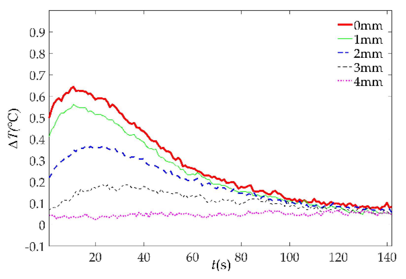
4.2. Experiment of Damage Detection
4.3. Experiment of Image Fusion Enhancement
5. Conclusions
Author Contributions
Funding
Conflicts of Interest
References
- Miao, Y.; Cai, G.; Guo, J. New Measurement Technology of Structural Silicone Sealant in Hidden Frame Supported Glass Curtain Wall Based on FFT Power Spectrum; IEEE Computer Society: Washington, DC, USA, 2011; pp. 92–95. [Google Scholar]
- Gu, J.; Hao, W.; Luo, Y. Investigation of damage identification for glass curtain wall based on Hilbert-Huang transform and transmissibility function. Int. J. Model. Identif. Control 2011, 13, 38–45. [Google Scholar] [CrossRef]
- Liu, X.; Bao, Y. Safety evaluation of glass curtain walls by using dynamic method. China Civ. Eng. J. 2009, 42, 11–15. [Google Scholar]
- Hong, X.; Liu, Y.; Lin, P.; Xu, W. Interfacial Adhesion-Strength Detection of Structural Silicone Sealant for Hidden Frame-Supported Glass Curtain Wall Based on Nonlinear Ultrasonic Lamb Wave. J. Aerosp. Eng. 2018, 31, 04018047. [Google Scholar] [CrossRef]
- Hong, X.; Liu, Y.; Liufu, Y.; Lin, P. Debonding Detection in Hidden Frame Supported Glass Curtain Walls Using the Nonlinear Ultrasonic Modulation Method with Piezoceramic Transducers. Sensors 2018, 18, 2094. [Google Scholar] [CrossRef] [PubMed]
- Memari, A.M.; Kremer, P.A.; Behr, R.A. Architectural Glass Panels with Rounded Corners to Mitigate Earthquake Damage. Earthq. Spectra 2012, 22, 129–150. [Google Scholar] [CrossRef]
- Weggel, D.C.; Zapata, B.J.; Kiefer, M.J. Properties and Dynamic Behavior of Glass Curtain Walls with Split Screw Spline Mullions. J. Struct. Eng. 2013, 133, 1415–1425. [Google Scholar] [CrossRef]
- Xu, B.; Song, G.; Masri, S.F. Damage detection for a frame structure model using vibration displacement measurement. Struct. Health Monit. 2012, 11, 281–292. [Google Scholar] [CrossRef]
- Xu, B.; Li, B.; Song, G. Active Debonding Detection for Large Rectangular CFSTs Based on Wavelet Packet Energy Spectrum with Piezoceramics. J. Struct. Eng. 2013, 139, 1435–1443. [Google Scholar] [CrossRef]
- Xu, B.; Zhang, T.; Song, G.; Gu, H. Active interface debonding detection of a concrete-filled steel tube with piezoelectric technologies using wavelet packet analysis. Mech. Syst. Signal Process. 2013, 36, 7–17. [Google Scholar] [CrossRef]
- Sethi, V.; Song, G. Multimode vibration control of a smart model frame structure. Smart Mater. Struct. 2006, 15, 473–479. [Google Scholar] [CrossRef]
- Sethi, V.; Song, G. Optimal Vibration Control of a Model Frame Structure Using Piezoceramic Sensors and Actuators. J. Vib. Control. 2005, 11, 671–684. [Google Scholar] [CrossRef]
- Yi, T.; Li, H.; Song, G.; Zhang, X. Optimal sensor placement for health monitoring of high-rise structure using adaptive monkey algorithm. Struct. Control. Health Monit. 2015, 22, 667–681. [Google Scholar] [CrossRef]
- Li, D.; Ren, L.; Li, H.; Song, G. Structural Health Monitoring of a Tall Building during Construction with Fiber Bragg Grating Sensors. Int. J. Distrib. Sens. Netw. 2012, 2012, 1146–1149. [Google Scholar] [CrossRef]
- Zhao, X.; Li, M.; Song, G.; Xu, J. Hierarchical ensemble-based data fusion for structural health monitoring. Smart Mater. Struct. 2010, 19, 045009. [Google Scholar] [CrossRef]
- Lahiri, B.B.; Bagavathiappan, S.; Jayakumar, T.; Philip, J. Medical applications of infrared thermography: A review. Infrared Phys. Technol. 2012, 55, 221–235. [Google Scholar] [CrossRef]
- Yang, Z.; Luo, Q.; Tian, G.; Yang, B.; Zhang, W.; Zhu, J. Design and implement of infrared thermography detection system excited by pulsed flash lamp. Manuf. Technol. 2015, 15, 249–254. [Google Scholar]
- Pickering, S.G.; Chatterjee, K.; Almond, D.P.; Tuli, S. LED optical excitation for the long pulse and lock-in thermographic techniques. NDT E Int. 2013, 58, 72–77. [Google Scholar] [CrossRef]
- Chen, D.; Xing, C.; Zhang, Z.; Zhang, C. Terahertz thermal wave nondestructive test. Acta Phys. Sin. 2012, 61, 269–274. [Google Scholar]
- Keo, S.A.; Brachelet, F.; Defer, D.; Breaban, F. Defects detection by infrared thermography with a new, microwave excitation system. Mech. Ind. 2014, 15, 509–516. [Google Scholar] [CrossRef]
- Tao, N.; Zeng, Z.; Feng, L.; Li, X.; Li, Y.; Zhang, C. The Application of Pulsed Thermography in the Inspection of Wind Turbine Blades; International Society for Optics and Photonics: Bellingham, WA, USA, 2011; pp. 9879–9891. [Google Scholar]
- Chen, L.; Yang, L.; Fan, C. Quantitative identification of coating thickness and debonding defects of TBC by pulse phase technology. Infrared Laser Eng. 2015, 44, 2050–2056. [Google Scholar]
- Brown, J. Comparison of Lock-In and Pulse-Phase Thermography for Defect Characterization in FRP Composites Applied to Concrete; International Society for Optics and Photonics: Bellingham, WA, USA, 2015; pp. 865–868. [Google Scholar]
- Guo, X.; Li, R.; Ding, M. Simulating modulated thermography of cladding debond in solid rockets. J. Mech. Eng. 2011, 47, 9–15. [Google Scholar] [CrossRef]
- Subbarao, G.V.; Mulaveesala, R. Quadratic Frequency Modulated Thermal Wave Imaging for Non-Destructive Testing. Pier M 2012, 52, 11–22. [Google Scholar] [CrossRef]
- Zheng, K.; Chang, Y.; Wang, K.; Yao, Y. Improved non-destructive testing of carbon fiber reinforced polymer (CFRP) composites using pulsed thermograph. Polym. Test. 2015, 46, 26–32. [Google Scholar] [CrossRef]
- Shepard, S.M. Flash Thermography of Aerospace Composites. IV Conferencia Panamericana de END, Buenos Aires. 2007. Available online: https://www.semanticscholar.org/paper/Flash-Thermography-of-Aerospace-Composites-Shepard/f498f67f766ebb331aeb7d772823265b6ebf604c (accessed on 17 October 2018).
- Chapuis, B. Improvement of the detection of defects by pulse thermography thanks to the TSR approach in the case of a smart composite repair patch. Quant. Infrared Thermogr. J. 2010, 7, 167–187. [Google Scholar]
- Manohar, A.; Scalea, F.L.D. Wavelet-Aided Multivariate Outlier Analysis to Enhance Defect Contrast in Thermal Images. Exp. Tech. 2011, 38, 28–37. [Google Scholar] [CrossRef]
- Wang, J.; Cao, Z.; Yang, B.; Ma, S.; Fei, M.; Huang, S.; Yao, Y.; Chen, T.; Wang, X. Non-destructive testing of CFRP using pulsed thermographic data enhanced by wavelet transform-based image denoising. In Proceedings of the 2017 36th Chinese Control Conference (CCC), Dalian, China, 26–28 July 2017; pp. 5555–5559. [Google Scholar]
- Wu, Y.; Yin, J. Enhancement of infrared thermal wave images based on contourlet and adaptive chaotic variation particle swarm optimization. Syst. Eng. Electron. 2015, 37, 443–448. [Google Scholar]
- Yang, Z.; Zhang, W. Thermography Testing and Quantitative Identification for Adhesive Structure of Solid Rocket Motor; National Defense Industry Press: Beijing, China, 2015. [Google Scholar]
- Kashcooli, M.; Salimpour, M.R.; Shirani, E. Heat transfer analysis of skin during thermal therapy using thermal wave equation. J. Therm. Biol. 2017, 64, 7–18. [Google Scholar] [CrossRef] [PubMed]
- Ji, X.; Cheng, J.; Tao, D.; Wu, X.; Feng, W. The spatial Laplacian and temporal energy pyramid representation for human action recognition using depth sequences. Knowl.-Based Syst. 2017, 122, 64–74. [Google Scholar] [CrossRef]
- Zhu, B.; Cao, W.; Cai, X.; Dong, X.G.; Wang, C.G. Simulation study on the radiative heat flux intensity distribution of carbon matrix composites electric heater. J. Funct. Mater. 2011, 42, 745–752. [Google Scholar]


| Length l0 (mm) | Diameter R (mm) | Power P (W) | Electro-Thermal Radiation η (%) | Radiant Rate of Glass εg |
|---|---|---|---|---|
| 240 | 10 | 600 | 98 | 0.94 |
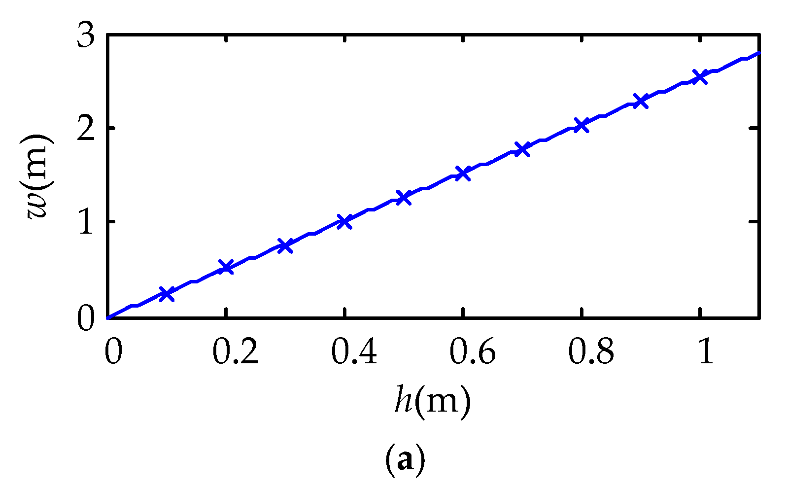
| Radiation Distance h (mm) | Distance of Adjacent Carbon Fiber Radiators w (mm) | Normalized Uniformity UNn (W/m2) | Uniformity UN (W/m2) |
|---|---|---|---|
| 76 | 192 | 0.87 | 983 |
| Luminous Flux ψ(W) | Radiation Type | The Optical Properties of the Inner Surface of the Reflector | The Number of Lights |
|---|---|---|---|
| 588 | Lambertian | Diffuse reflection | 200,000 |
| Temperature (°C) | Humidity (%) | Weather | Solar Incident Angle (°) |
|---|---|---|---|
| 30 ± 0.2 | 84 ± 5 | Sunny day | 90 |
© 2018 by the authors. Licensee MDPI, Basel, Switzerland. This article is an open access article distributed under the terms and conditions of the Creative Commons Attribution (CC BY) license (http://creativecommons.org/licenses/by/4.0/).
Share and Cite
Hong, X.; Lin, J.; Liu, Y.; Xu, W. Active Thermal Sensing for Bonding Structure Damage Detection of Hidden Frame Glass Curtain Wall. Sensors 2018, 18, 3594. https://doi.org/10.3390/s18113594
Hong X, Lin J, Liu Y, Xu W. Active Thermal Sensing for Bonding Structure Damage Detection of Hidden Frame Glass Curtain Wall. Sensors. 2018; 18(11):3594. https://doi.org/10.3390/s18113594
Chicago/Turabian StyleHong, Xiaobin, Jinfan Lin, Yuan Liu, and Weiying Xu. 2018. "Active Thermal Sensing for Bonding Structure Damage Detection of Hidden Frame Glass Curtain Wall" Sensors 18, no. 11: 3594. https://doi.org/10.3390/s18113594
APA StyleHong, X., Lin, J., Liu, Y., & Xu, W. (2018). Active Thermal Sensing for Bonding Structure Damage Detection of Hidden Frame Glass Curtain Wall. Sensors, 18(11), 3594. https://doi.org/10.3390/s18113594