
An Improved Model Predictive Current Controller of Switched Reluctance Machines Using Time-Multiplexed Current Sensor


Abstract
:1. Introduction
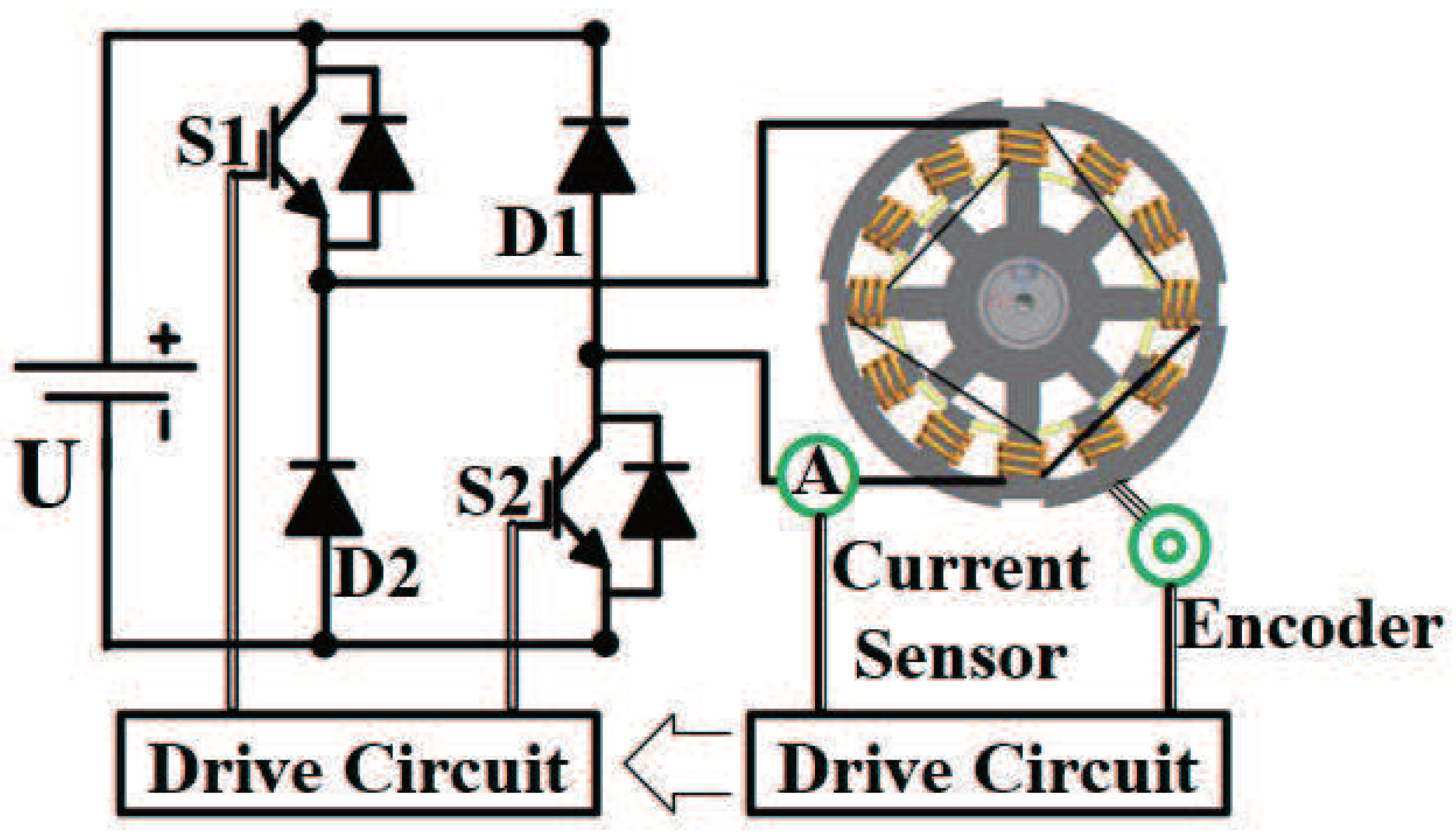
2. Control System Using a Multiplexed Current Sensor
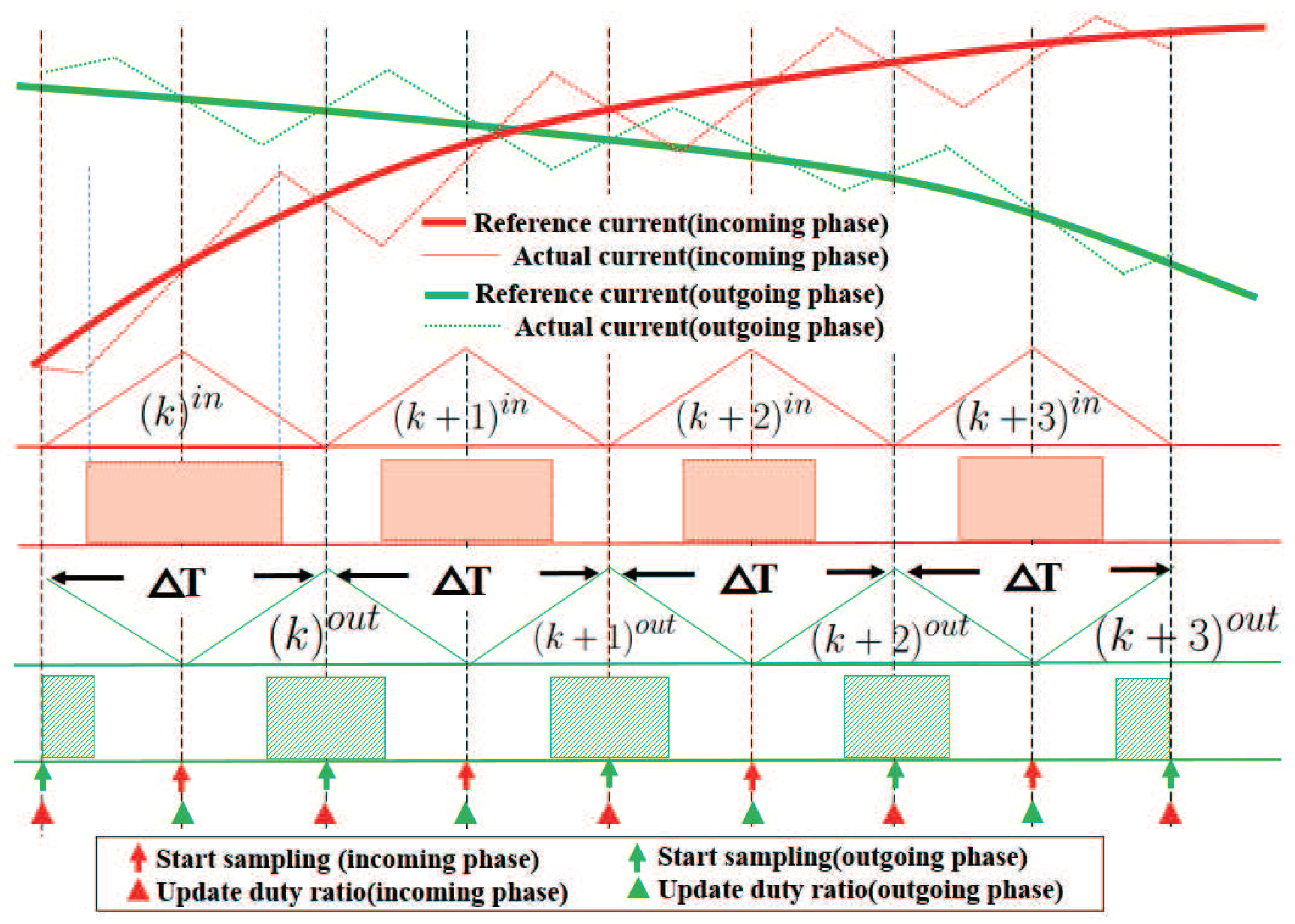
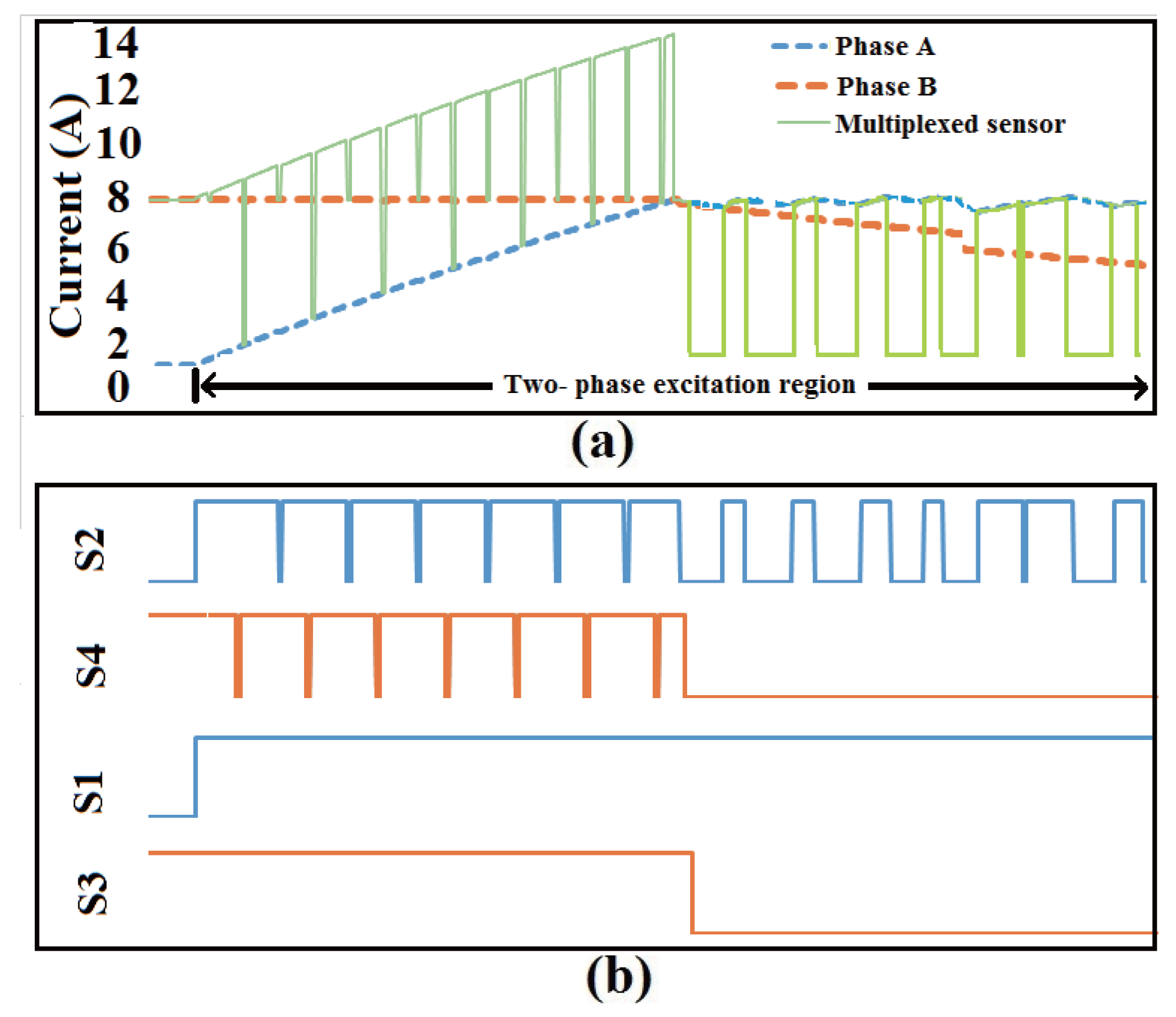
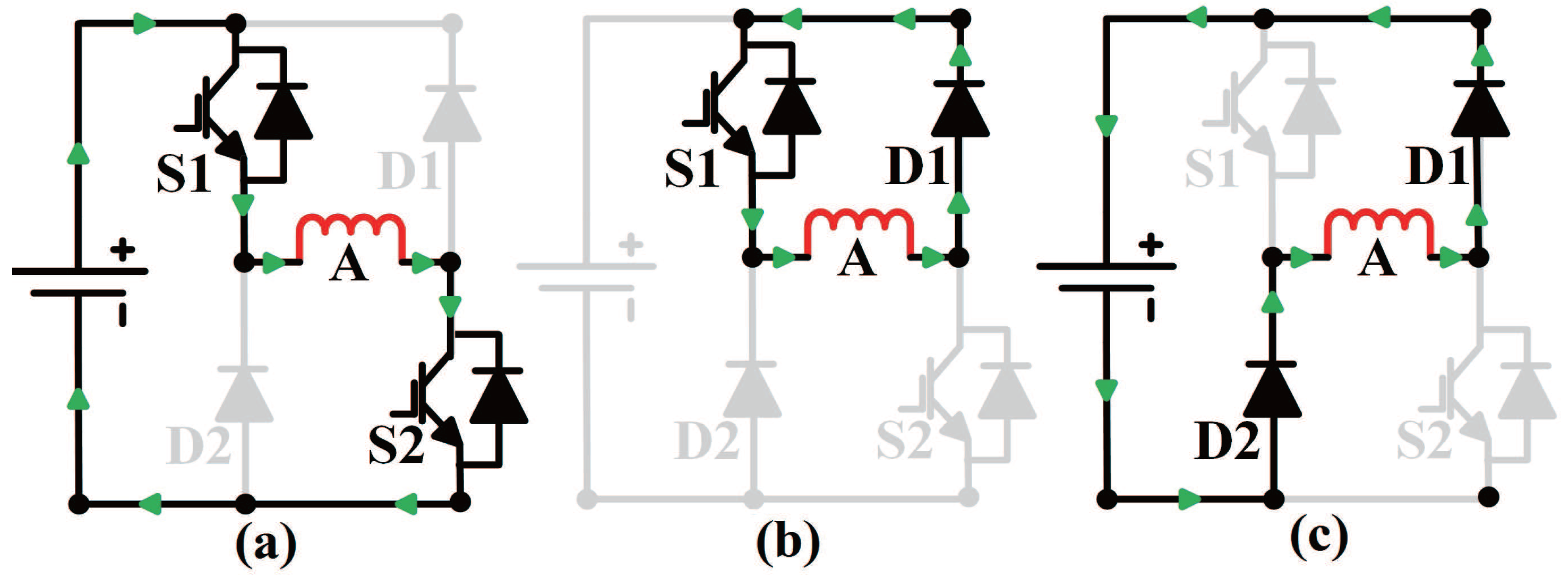
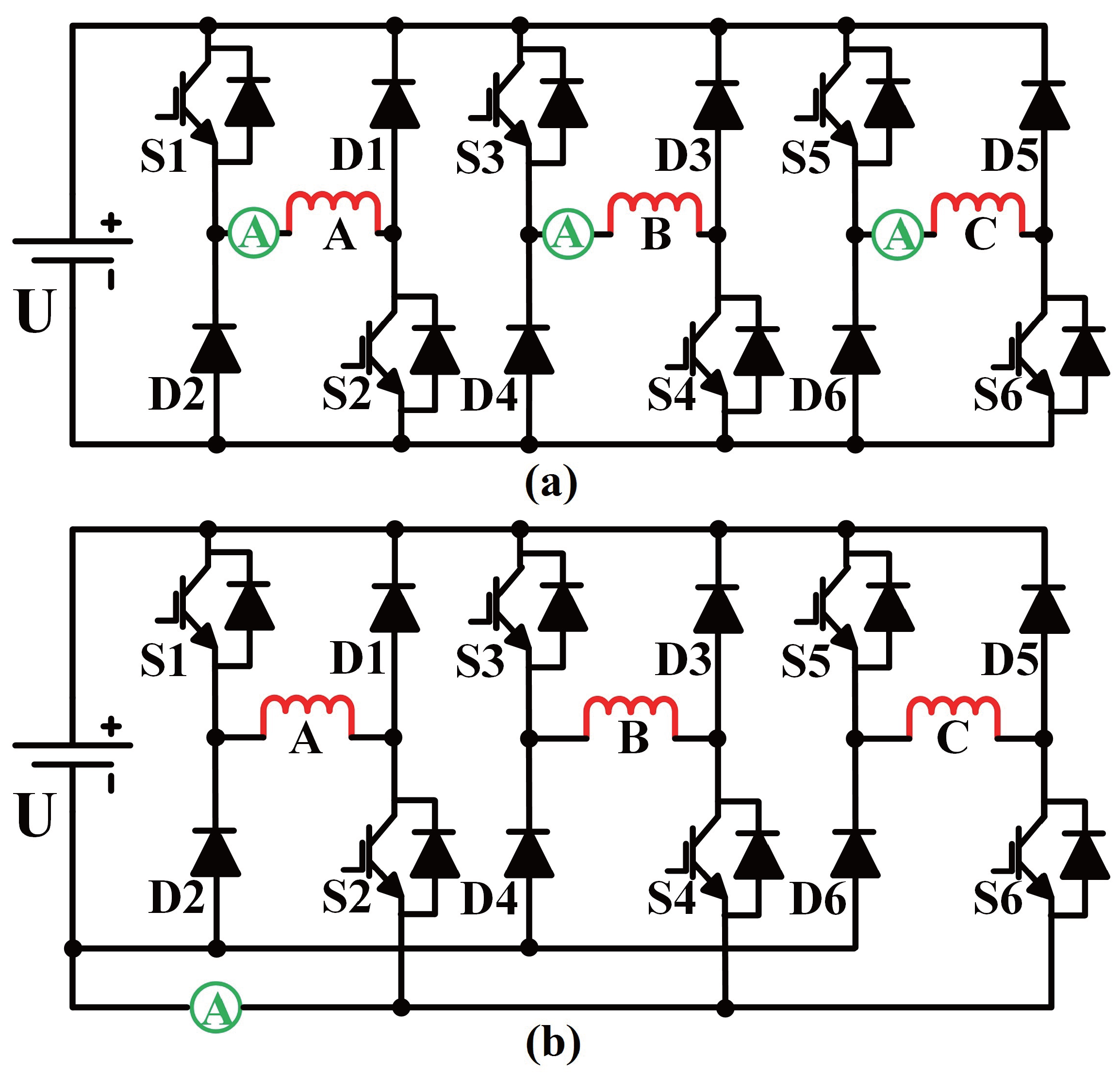
2.1. Principle of Current Sensor Multiplexing
2.2. Sensor Multiplexing Integrated in Model Predictive Control
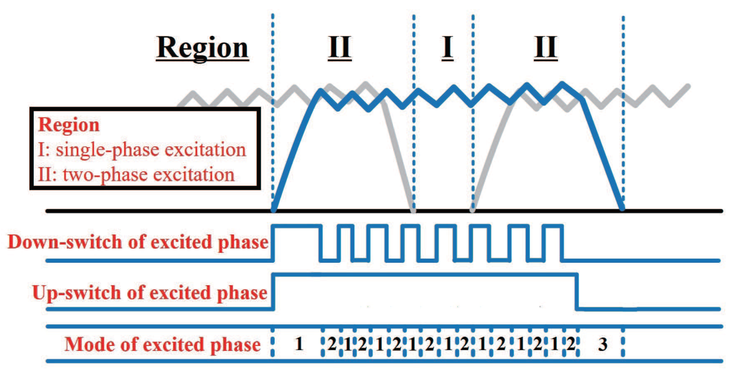
2.2.1. Scheme of Predictive Control
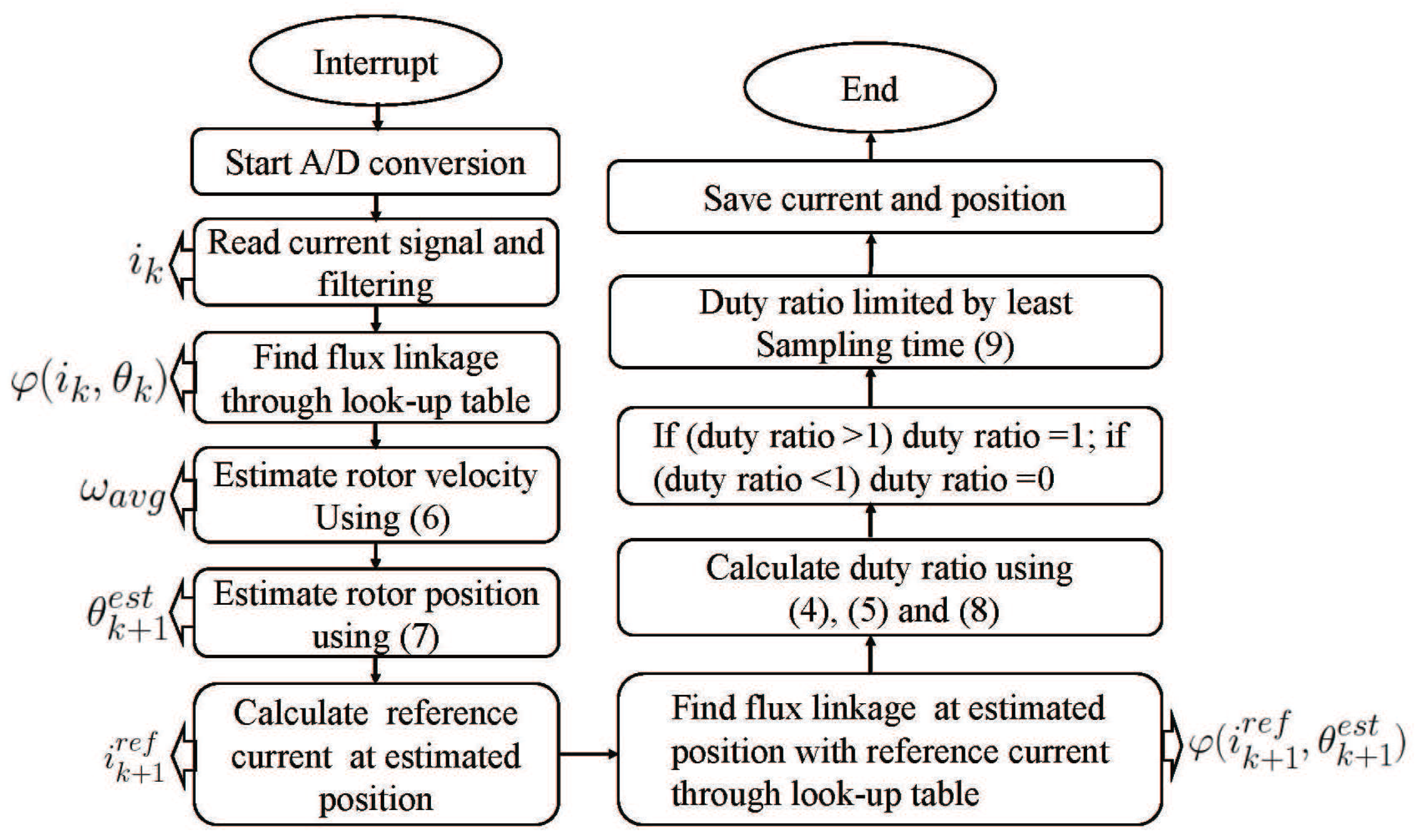
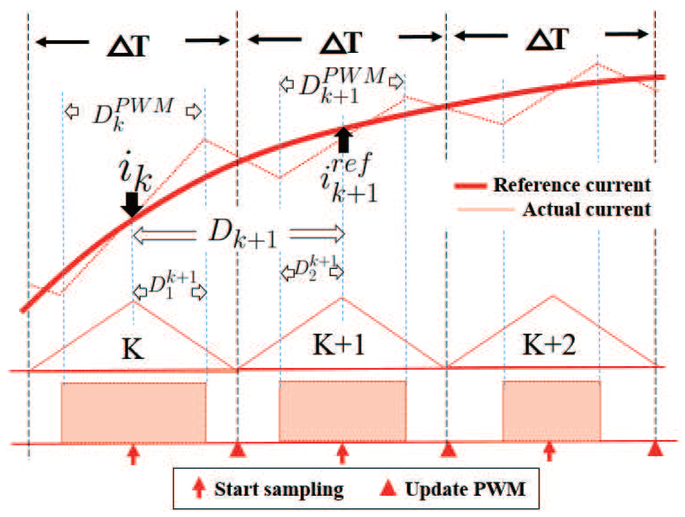
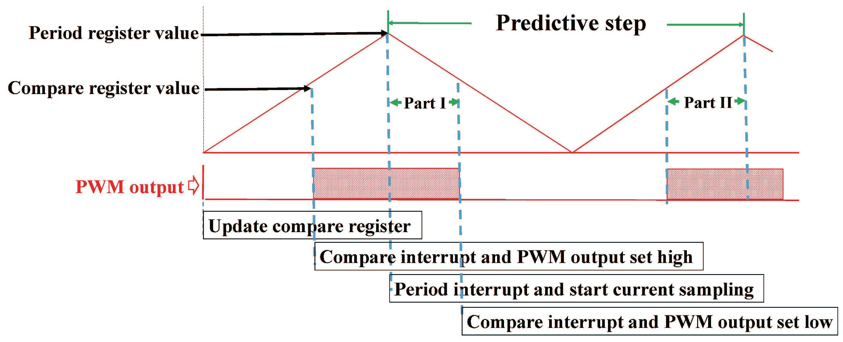
2.2.2. Model Predictive Current Control with Single Current Sensor
- Avoid errors due to current ringings. Current ringings are generated at a switching instant due to parasitics and nonidealities of the switching devices and the inverter. These ringings introduce errors in the sampled current. Current sampling at the middle of a time period leaves enough time for current ringing to decay.
- Leave enough time for calculating duty ratio using predictive model before compare register updates.
3. Simulation and Experimental Results
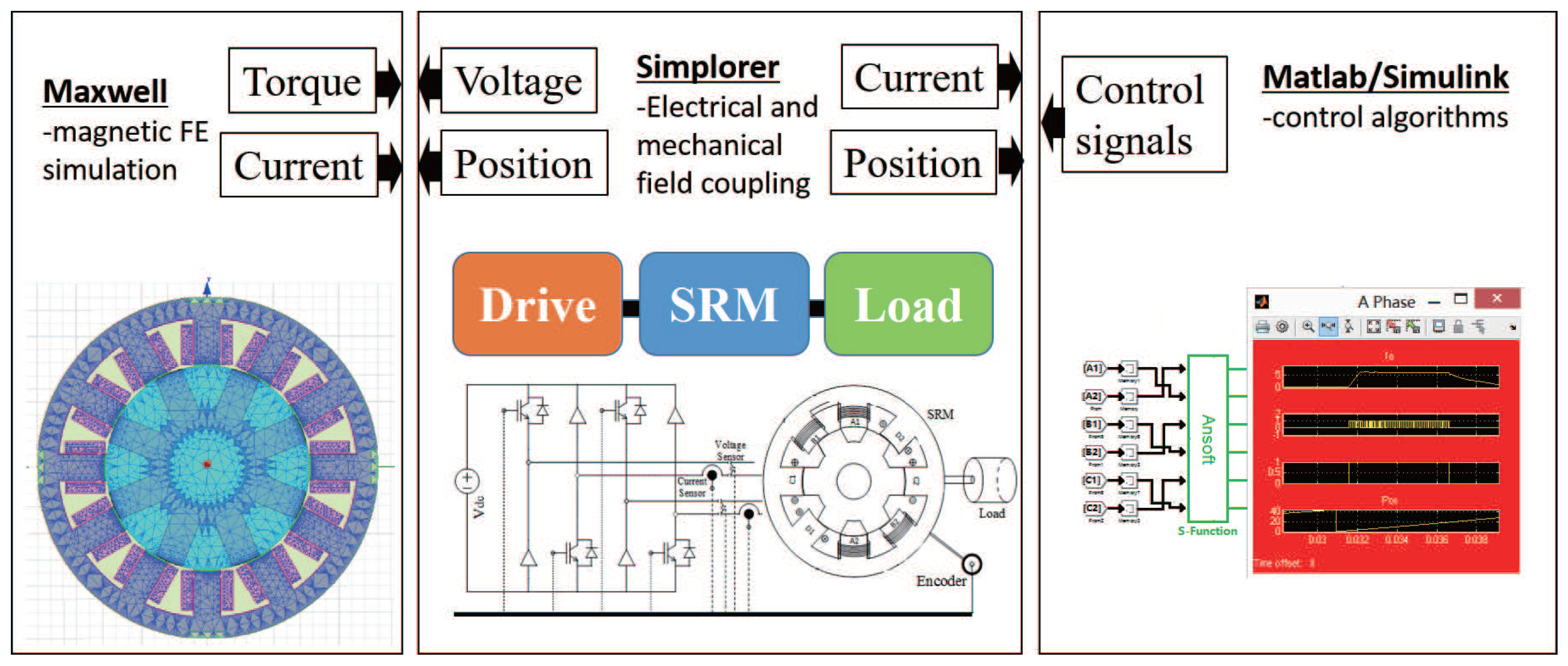
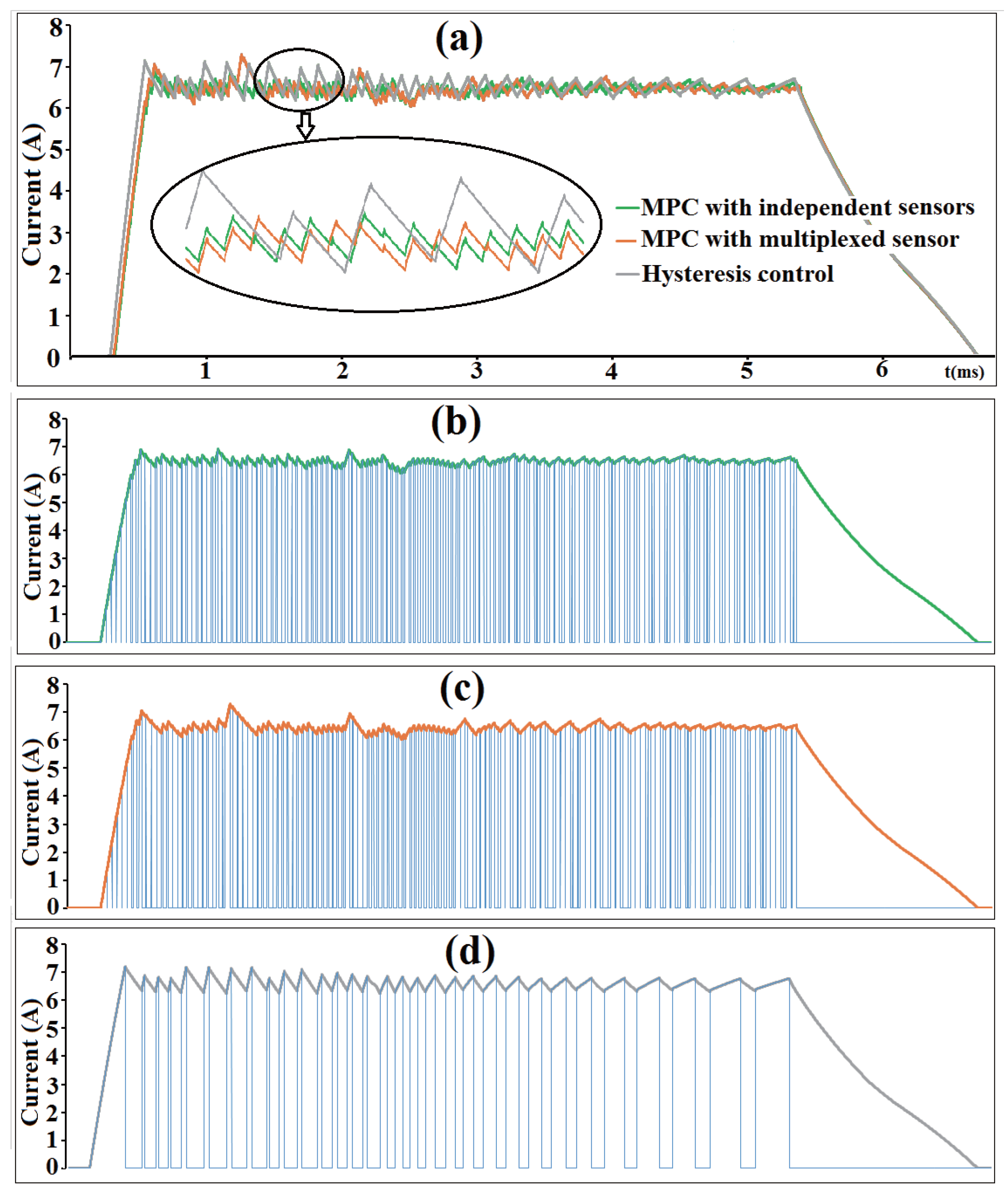
3.1. Simulation
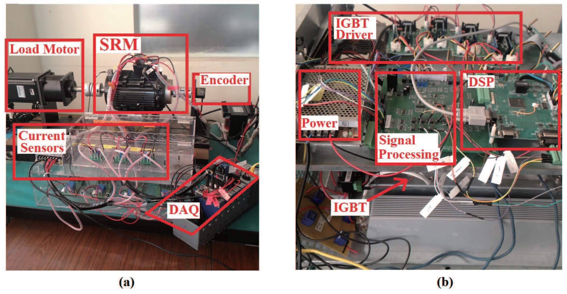
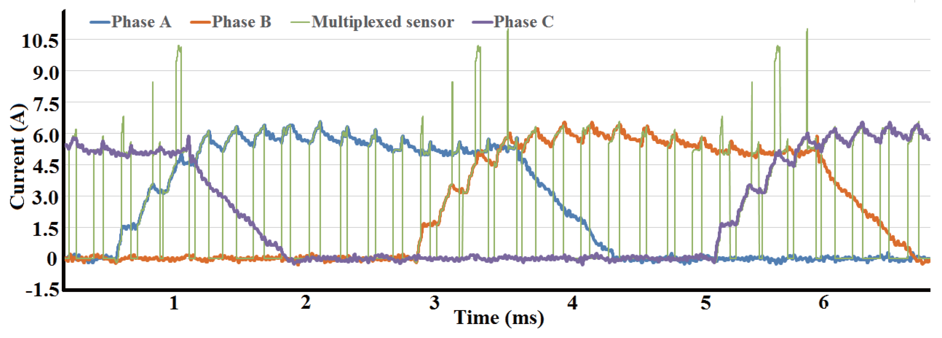
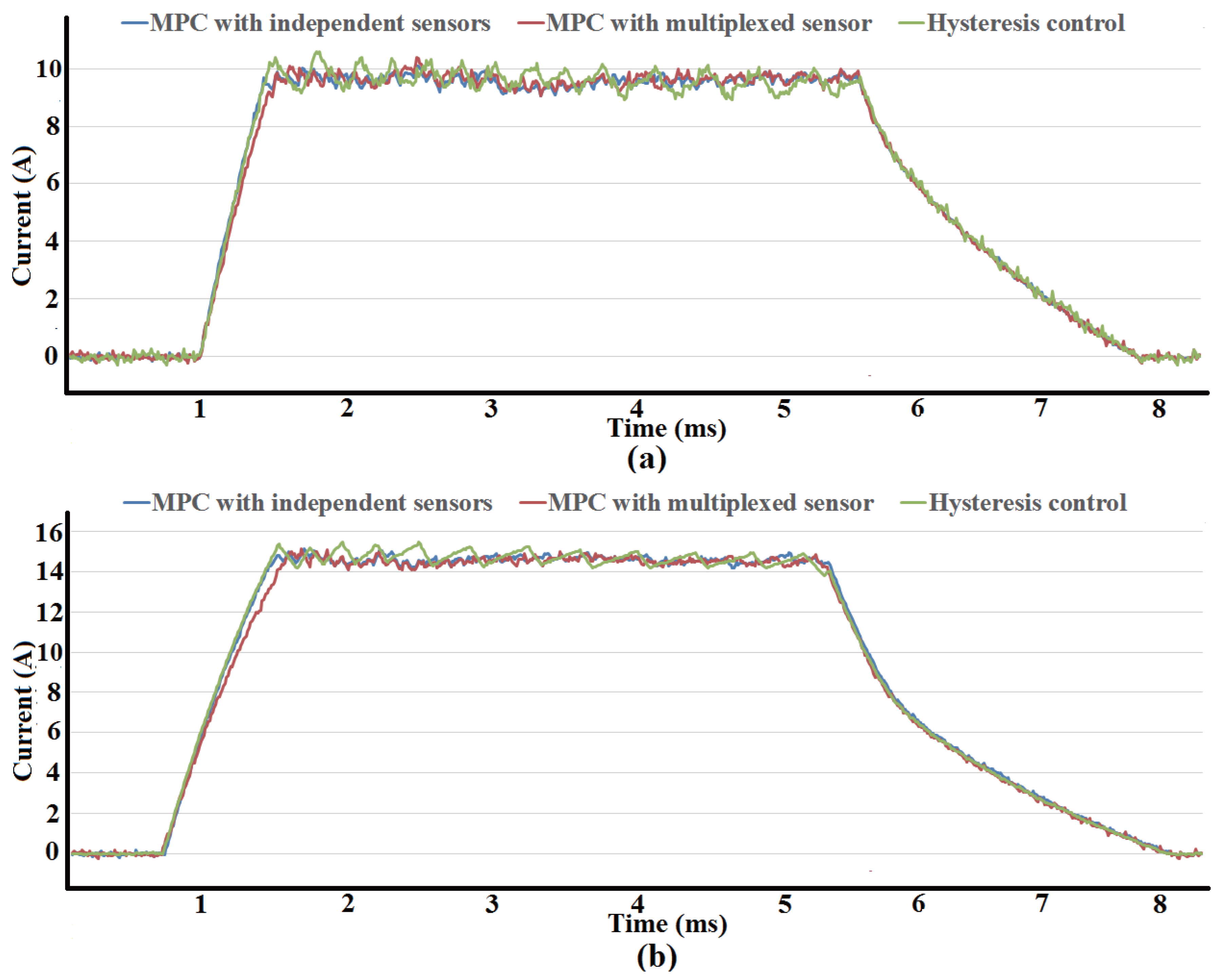
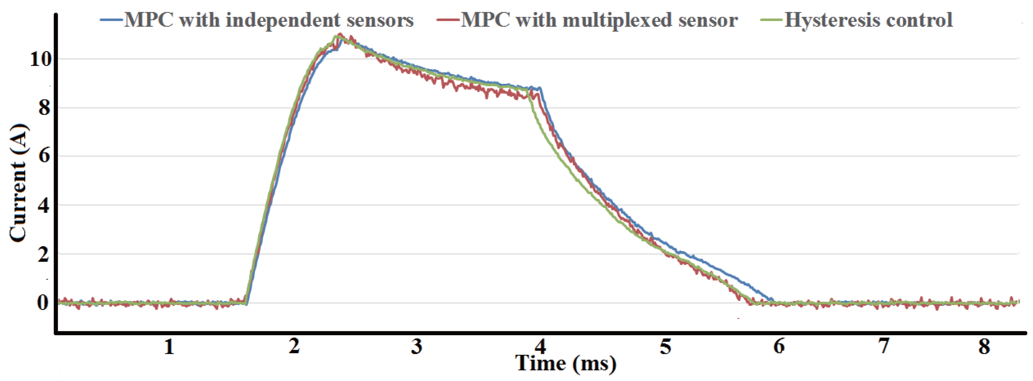
3.2. Experiment
4. Conclusions
Acknowledgments
Author Contributions
Conflicts of Interest
Abbreviations
| SRM | Switched reluctance machine |
| A/D | Analog-to-Digital Converter |
| PWM | Pulse Width Modulation |
| MPC | Model Predictive Control |
| KCL | Kirchhoff Current Law |
| DAQ | Data Acquisition |
| IGBT | Insulated Gate Bipolar Transistor |
References
- Inderka, R.B.; Menne, M.; De Doncker, R.W.A.A. Control of switched reluctance drives for electric vehicle applications. IEEE Trans. Ind. Electron. 2008, 49, 48–53. [Google Scholar] [CrossRef]
- Cardenas, R.; Pena, R.; Perez, M. Control of a switched reluctance generator for variable-speed wind energy applications. IEEE Trans. Energy Convers. 2005, 20, 781–791. [Google Scholar] [CrossRef]
- Husain, I. Minimization of torque ripple in SRM drives. IEEE Trans. Ind. Electron. 2002, 49, 28–39. [Google Scholar] [CrossRef]
- Colby, R.S.; Mottier, F.M.; Miller, T.J.E. Vibration modes and acoustic noise in a four-phase switched reluctance. IEEE Trans. Ind. Appl. 1996, 32, 1357–1364. [Google Scholar] [CrossRef]
- Xue, X.D.; Cheng, K.W.E.; Ho, S.L. Optimization and evaluation of torque-sharing functions for torque ripple minimization in switched reluctance motor drives. IEEE Trans. Power Electr. 2009, 24, 2076–2090. [Google Scholar] [CrossRef]
- Vujičić, V.P. Minimization of Torque Ripple and Copper Losses in Switched Reluctance Drive. IEEE Trans. Power Electr. 2012, 27, 388–399. [Google Scholar] [CrossRef]
- Moehle, N.; Boyd, S. Optimal current waveforms for switched-reluctance motors. In Proceedings of the 2016 IEEE Conference on Control Applications (CCA), Buenos Aires, Argentina, 19–22 September 2016; pp. 1129–1136. [Google Scholar] [CrossRef]
- Karthikeyan, R.; Vijayakumar, K.; Paramasivam, S.; Arumugan, R.; Srinivas, K.N. Switched reluctance motor modeling, design, simulation, and analysis: A comprehensive review. IEEE Trans. Magn. 2008, 44, 4605–4617. [Google Scholar] [CrossRef]
- Rajarathnam, A.V.; Rahman, K.M.; Ehsani, M. Improvement of hysteresis control in switched reluctance motor drives. In Proceedings of the IEEE International Electric Machines and Drives Conference (IEMD ’99), Seattle, WA, USA, 9–12 May 1999; pp. 537–539. [Google Scholar] [CrossRef]
- Ye, J.; Bilgin, B.; Emadi, A. An offline torque sharing function for torque ripple reduction in switched reluctance motor drives. IEEE Trans. Energy Convers. 2015, 30, 726–735. [Google Scholar] [CrossRef]
- Schulz, S.E.; Rahman, K.M. High-performance digital PI current regulator for EV switched reluctance motor drives. IEEE Trans. Ind. Appl. 2003, 39, 1118–1126. [Google Scholar] [CrossRef]
- Peng, F.; Ye, J.; Emadi, A. A digital PWM current controller for switched reluctance motor drives. IEEE Trans. Power Electr. 2016, 31, 7087–7098. [Google Scholar] [CrossRef]
- Sahoo, S.K.; Panda, S.K.; Xu, J.K. Iterative learning-based high-performance current controller for switched reluctance motors. IEEE Trans. Energy Convers. 2004, 19, 491–498. [Google Scholar] [CrossRef]
- Ye, J.; Malysz, P.; Emadi, A. A fixed-switching-frequency integral sliding mode current controller for switched reluctance motor drives. IEEE J. Sel. Top. Power Electr. 2015, 3, 381–394. [Google Scholar] [CrossRef]
- Mikail, R.; Husain, I.; Sozer, Y.; Islam, M.S.; Sebastian, T. A fixed switching frequency predictive current control method for switched reluctance machines. IEEE Trans. Ind. Appl. 2014, 50, 3717–3726. [Google Scholar] [CrossRef]
- Li, X.; Shamsi, P. Model predictive current control of switched reluctance motors with inductance auto-calibration. IEEE Trans. Ind. Electron. 2016, 63, 3934–3941. [Google Scholar] [CrossRef]
- Cho, Y.; LaBella, T.; Lai, J.S. A three-Phase current reconstruction strategy with online current offset compensation using a single current sensor. IEEE Trans. Ind. Electron. 2012, 59, 2924–2933. [Google Scholar] [CrossRef]
- Xia, C.; Li, Z.; Shi, T. A control strategy for four-switch three-phase brushless dc motor using single current sensor. IEEE Trans. Ind. Electron. 2009, 56, 2058–2066. [Google Scholar] [CrossRef]
- Sun, K.; Wei, Q.; Huang, L.; Matsuse, K. An overmodulation method for PWM-inverter-fed IPMSM drive with single current sensor. IEEE Trans. Ind. Electron. 2010, 57, 3395–3404. [Google Scholar] [CrossRef]
- Gan, C.; Wu, J.H.; Yang, S.Y.; Hu, Y.H. Phase current reconstruction of switched reluctance motors from DC-link current under double high-frequency pulses injection. IEEE Trans. Ind. Electron. 2015, 62, 3265–3276. [Google Scholar] [CrossRef]
- Barnes, M.; Pollock, C. Power electronic converters for switched reluctance drives. IEEE Trans. Power Electr. 1998, 13, 1100–1111. [Google Scholar] [CrossRef]
- Xue, X.D.; Cheng, K.W.E.; Lin, J.K.; Zhang, Z.; Luk, K.F.; Ng, T.W.; Cheung, N.C. Optimal Control Method of Motoring Operation for SRM Drives in Electric Vehicles. IEEE Trans. Veh. Technol. 2010, 59, 1191–1204. [Google Scholar] [CrossRef]


| Phase A | S | S |
|---|---|---|
| Mode I | ON | ON |
| Mode II | ON | OFF |
| Mode III | OFF | OFF |
| Combination | Sampling Current | Phase A | Phase B | Phase C |
|---|---|---|---|---|
| 1 | + | Mode I | Mode I | Not excited |
| 2 | Mode II or Mode III | Mode I | Not excited | |
| 3 | Mode I | Mode II or Mode III | Not excited | |
| 4 | 0 | Mode II or Mode III | Mode II or Mode III | Not excited |
| Parameter | Value |
|---|---|
| Number of rotor poles | 8 |
| Number of stator poles | 12 |
| Stator outer diameter | 130 mm |
| Rotor outer diameter | 77.4 mm |
| Stator outer diameter | 130 mm |
| Stator pole arc | |
| Rotor pole arc |
© 2017 by the authors. Licensee MDPI, Basel, Switzerland. This article is an open access article distributed under the terms and conditions of the Creative Commons Attribution (CC BY) license (http://creativecommons.org/licenses/by/4.0/).
Share and Cite
Li, B.; Ling, X.; Huang, Y.; Gong, L.; Liu, C. An Improved Model Predictive Current Controller of Switched Reluctance Machines Using Time-Multiplexed Current Sensor. Sensors 2017, 17, 1146. https://doi.org/10.3390/s17051146
Li B, Ling X, Huang Y, Gong L, Liu C. An Improved Model Predictive Current Controller of Switched Reluctance Machines Using Time-Multiplexed Current Sensor. Sensors. 2017; 17(5):1146. https://doi.org/10.3390/s17051146
Chicago/Turabian StyleLi, Bingchu, Xiao Ling, Yixiang Huang, Liang Gong, and Chengliang Liu. 2017. "An Improved Model Predictive Current Controller of Switched Reluctance Machines Using Time-Multiplexed Current Sensor" Sensors 17, no. 5: 1146. https://doi.org/10.3390/s17051146
APA StyleLi, B., Ling, X., Huang, Y., Gong, L., & Liu, C. (2017). An Improved Model Predictive Current Controller of Switched Reluctance Machines Using Time-Multiplexed Current Sensor. Sensors, 17(5), 1146. https://doi.org/10.3390/s17051146