
A Blade Tip Timing Method Based on a Microwave Sensor


Abstract
:1. Introduction
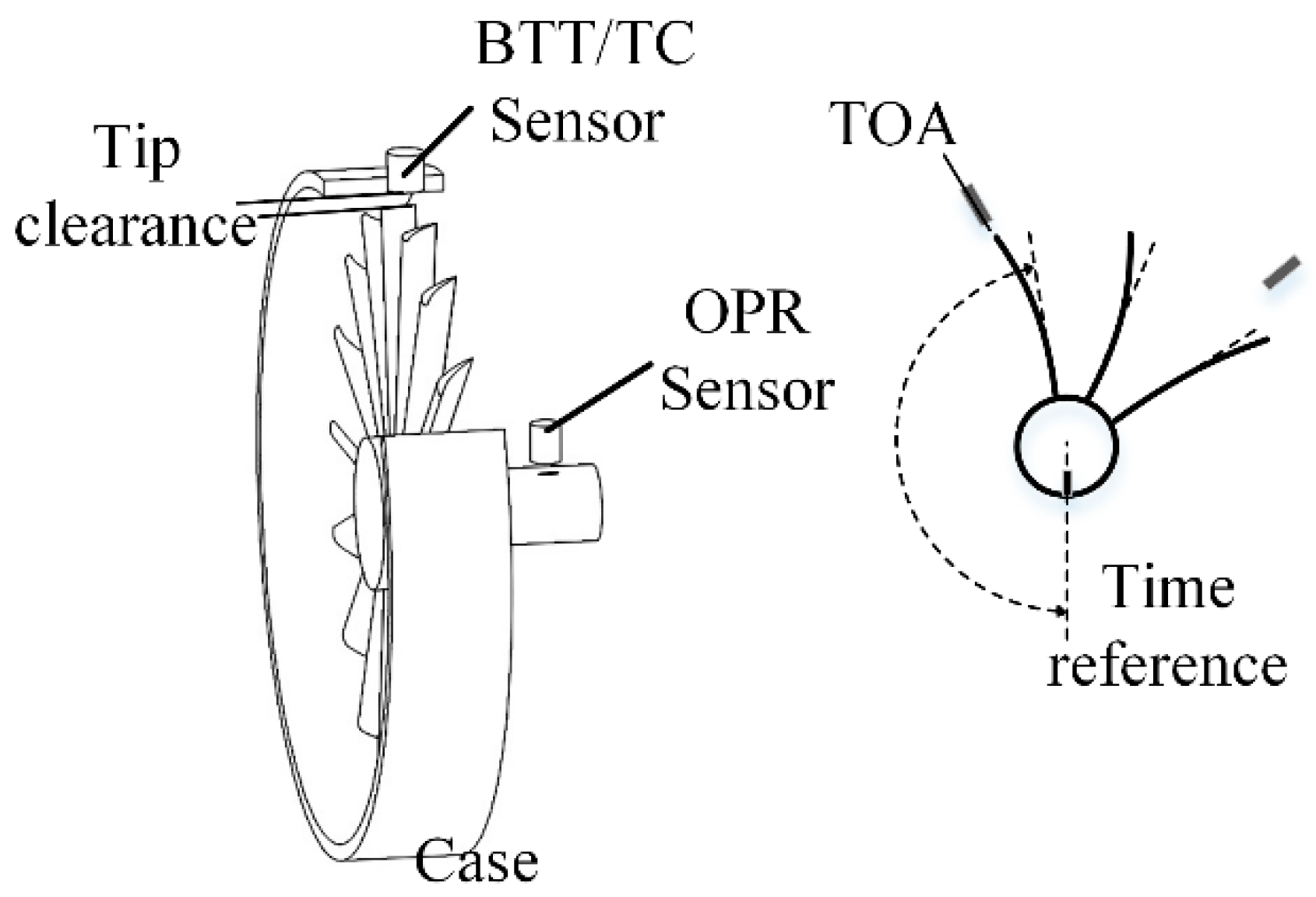
2. Microwave BTT System
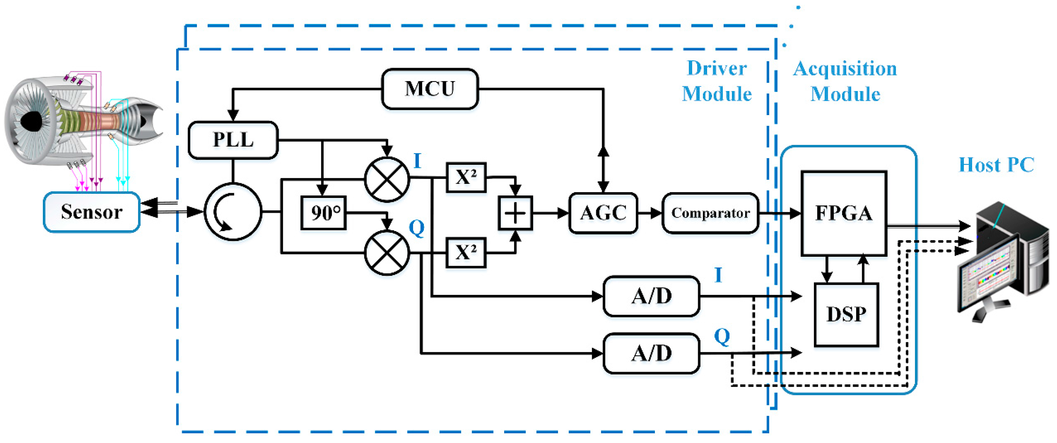
2.1. System Overview and Signal Analysis
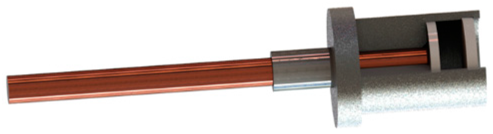
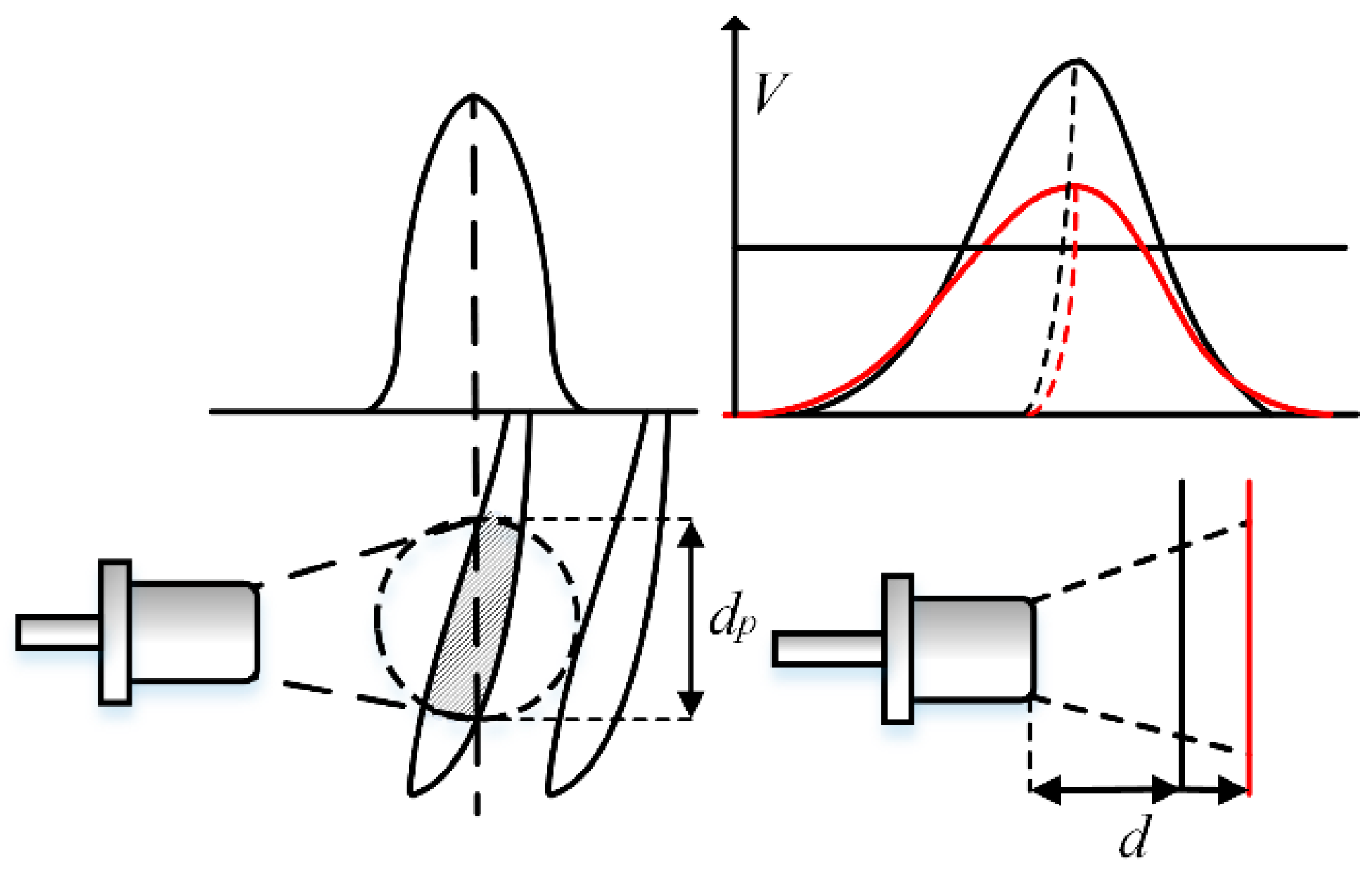
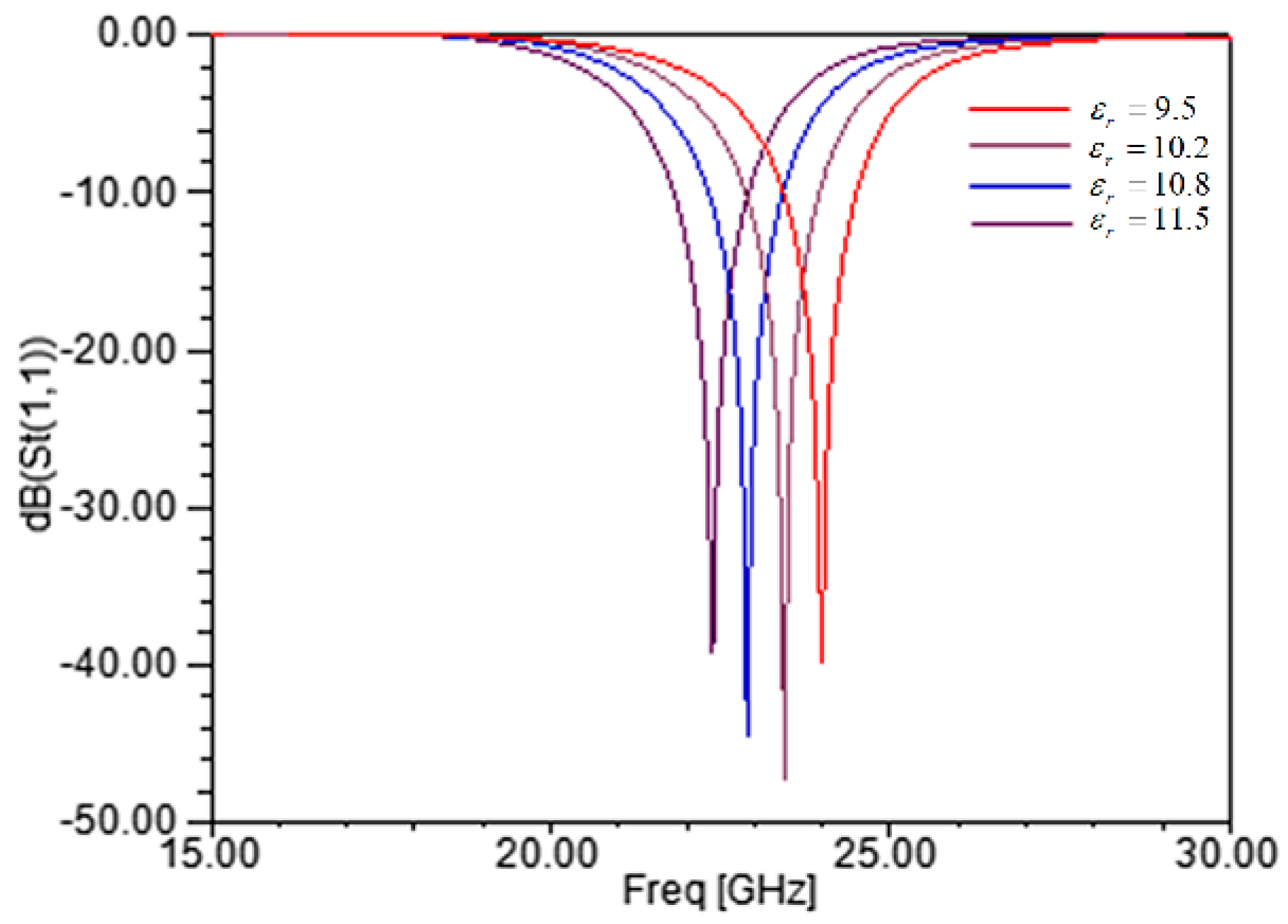
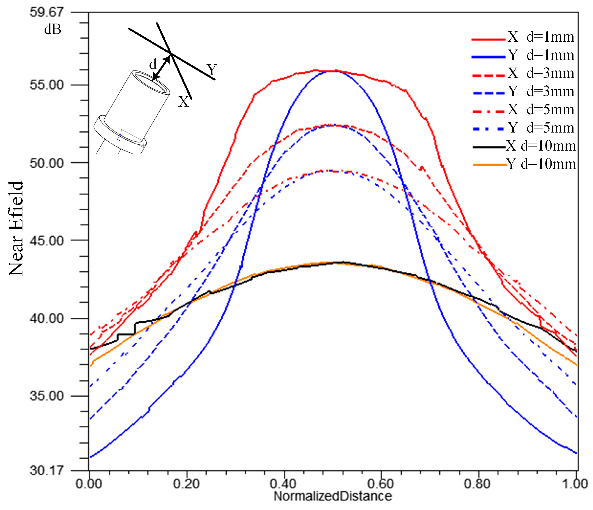
2.2. Microwave Sensor for BTT
2.3. Timing Method
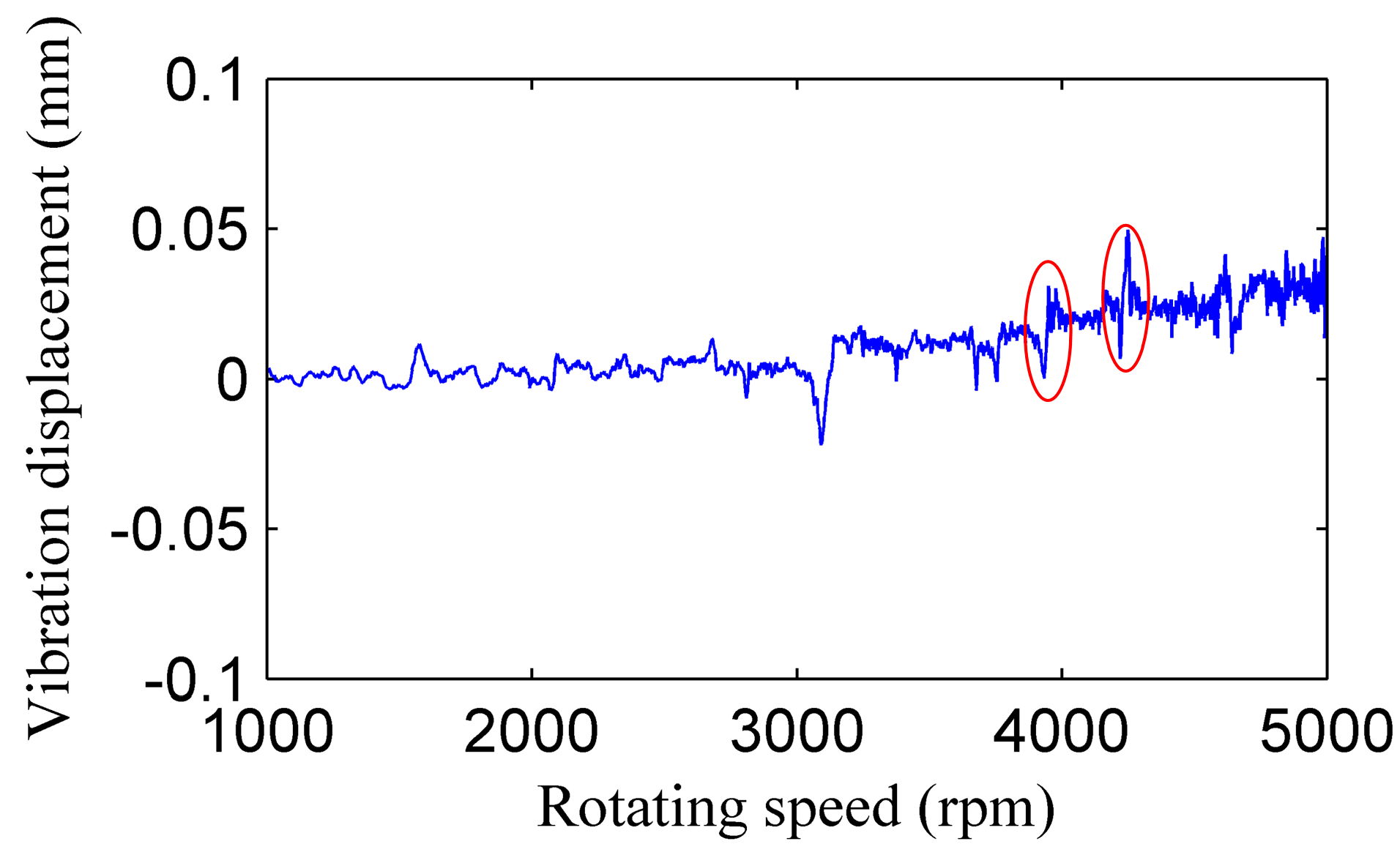
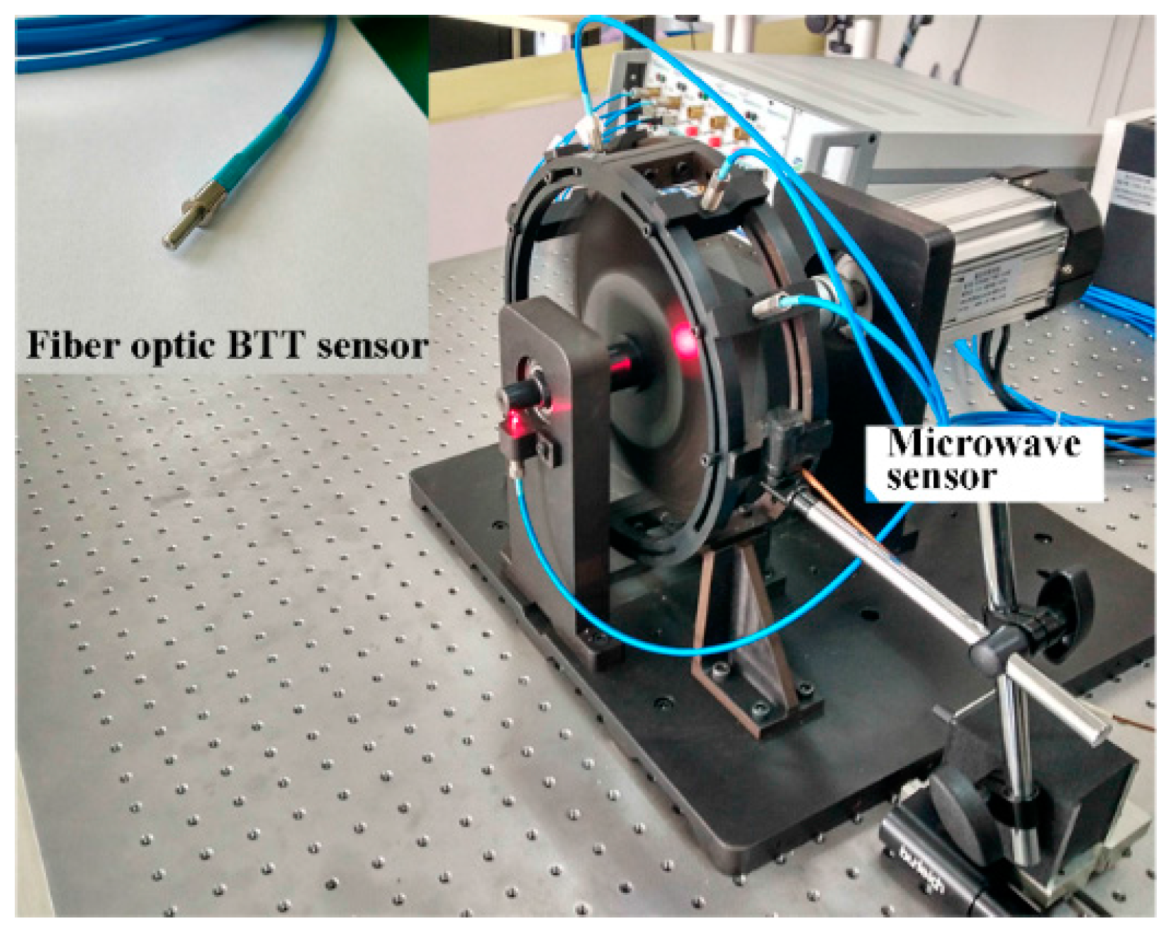
3. Experiments
4. Conclusions
Acknowledgments
Author Contributions
Conflicts of Interest
References
- Kumar, S.; Roy, N.; Ganguli, R. Monitoring low cycle fatigue damage in turbine blade using vibration characteristics. Mech. Syst. Signal Process. 2007, 21, 480–501. [Google Scholar] [CrossRef]
- Rao, A.R.; Dutta, B.K. Vibration analysis for detecting failure of compressor blade. Eng. Fail. Anal. 2012, 25, 211–218. [Google Scholar] [CrossRef]
- Salhi, B.; Lardies, J.; Berthillier, M.; Voinis, P.; Bodel, C. Modal parameter identification of mistuned bladed disks using tip timing data. J. Sound Vib. 2008, 314, 885–906. [Google Scholar] [CrossRef]
- Hanachi, H.; Liu, J.; Banerjee, A.; Koul, A.; Liang, M.; Alavi, E. Bladed disc crack diagnostics using blade passage signals. Meas. Sci. Technol. 2012, 23, 125003. [Google Scholar] [CrossRef]
- Diamond, D.H.; Heyns, P.S.; Oberholster, A.J. A comparison between three blade tip Timing algorithms for estimating synchronous turbomachine blade vibration. In Proceedings of the 9th World Congress on Engineering Asset Management (WCEAM), Pretoria, South Africa, 28–31 October 2014; pp. 215–225. [Google Scholar]
- Gallego-Garrido, J.; Dimitriadis, G.; Wright, J.R. A class of methods for the analysis of blade tip timing data from bladed assemblies undergoing simultaneous resonances—Part I: theoretical development. Int. J. Rotating Mach. 2007, 2007, 27247. [Google Scholar] [CrossRef]
- Hu, Z.; Lin, J.; Chen, Z.-S.; Yang, Y.-M.; Li, X.-J. A non-uniformly under-sampled blade tip-timing signal reconstruction method for blade vibration monitoring. Sensors 2015, 15, 2419–2437. [Google Scholar] [CrossRef] [PubMed]
- Wiseman, M.W.; Guo, T.H. An investigation of life extending control techniques for gas turbine engines. In Proceedings of the American Control Conference, Arlington, VA, USA, 25–27 July 2001; pp. 3706–3707. [Google Scholar]
- García, I.; Zubia, J.; Durana, G.; Aldabaldetreku, G.; Illarramendi, M.A.; Villatoro, J. Optical fiber sensors for aircraft structural health monitoring. Sensors 2015, 15, 15494–15519. [Google Scholar] [CrossRef] [PubMed]
- Guo, H.T.; Duan, F.J.; Cheng, Z. Numerical analysis of the blade tip-timing signal of a fiber bundle sensor probe. Opt. Eng. 2015, 54, 034103. [Google Scholar] [CrossRef]
- García, I.; Beloki, J.; Zubia, J.; Aldabaldetreku, G.; Illarramendi, M.A.; Jiménez, F. An Optical Fiber Bundle Sensor for Tip Clearance and Tip Timing Measurements in a Turbine Rig. Sensors 2013, 13, 7385–7398. [Google Scholar] [CrossRef] [PubMed]
- Pfister, T.; Büttner, L.; Czarske, J.; Krain, H.; Schodl, R. Turbo machine tip clearance and vibration measurements using a fibre optic laser doppler position sensor. Meas. Sci. Technol. 2006, 17, 1693–1705. [Google Scholar] [CrossRef]
- Michael, T. Method and Apparatus for Tracking a Rotating Blade Tip for Blade Vibration Monitor Measurements. Patent US7836772B2, 23 November 2010. [Google Scholar]
- Chana, K.S.; Cardwell, D.N. The use of eddy current sensor based blade tip timing for FOD detection. In Proceedings of the ASME Turbo Expo 2008: Power for Land, Sea, and Air, Berlin, Germany, 9–13 June 2008; pp. 169–178. [Google Scholar] [CrossRef]
- Cory, R.; Andreas, H.V. Passive Eddy Current Blade Detection Sensor. Patent US6927567B1, 9 August 2005. [Google Scholar]
- Cory, R.; Andreas, H.V.; Benjam, L. Blade Detection Sensor Having an Active Cooling System. Patent US7170284B2, 30 January 2007. [Google Scholar]
- Prochazka, P.; Vanek, F. New methods of noncontact sensing of blade vibrations and deflections in turbomachinery. IEEE Trans. Instrum. Meas. 2014, 63, 1583–1592. [Google Scholar] [CrossRef]
- Lawson, C.P.; Ivey, P.C. Tubomachinery blade vibration amplitude measurement through tip timing with capacitance tip clearance probes. Sensor Actuators A Phys. 2005, 118, 14–24. [Google Scholar] [CrossRef]
- Gilles, B.; Samim, A. Capactive Sensor Including a Coaxial Cable and a Probe. Patent US5973502, 26 October 1999. [Google Scholar]
- Geisheimer, J.L.; Billington, S.A.; Holst, T.; Burgess, D.W. Performance testing of a microwave tip clearance sensor. In Proceedings of the AIAA Joint Propulsion Conference, Tucson, AZ, USA, 10–13 July 2005. [Google Scholar] [CrossRef]
- Ryszard, S.; Radosław, P.; Jarosław, S.; Edward, R.; Krzysztof, K.; Paweł, M. Application of Blade-Tip Sensors to Blade-Vibration Monitoring in Gas Turbines. In Thermal Power Plants, 1st ed.; Mohammad, R., Ed.; InTech: Rijeka, Croatia, 2012; Volume 8, pp. 145–176. [Google Scholar]
- Alexander, M.; Mikhail, B.; Maksim, S. Microwave blade tip clearance measurements: principles, current practices and future opportunities. In Proceedings of the ASME Turbo Expo 2012, Copenhagen, Denmark, 11–15 June 2012. [Google Scholar] [CrossRef]
- Wagner, M.; Schulze, A.; Vossiek, M.; Stephelbauer, C.; Weigel, R.; Vortmeyer, N.; Heide, P. Novel microwave vibration monitoring system for industrial power generating turbines. In Proceedings of the IEEE MTT-S International Microwave Symposium Digest, Baltimore, MD, USA, 7–12 June 1998; pp. 143–146. [Google Scholar] [CrossRef]
- Violetti, M.; Xu, Q.; Hochreutiner, O.; Skrivervik, A.K. New microwave sensor for on-line blade tip timing in gas and steam turbines. In Proceedings of the 2012 Asia-Pacific Microwave Conference (APMC 2012), Kaohsiung, Taiwan, 4–7 December 2012; pp. 1055–1057. [Google Scholar] [CrossRef]


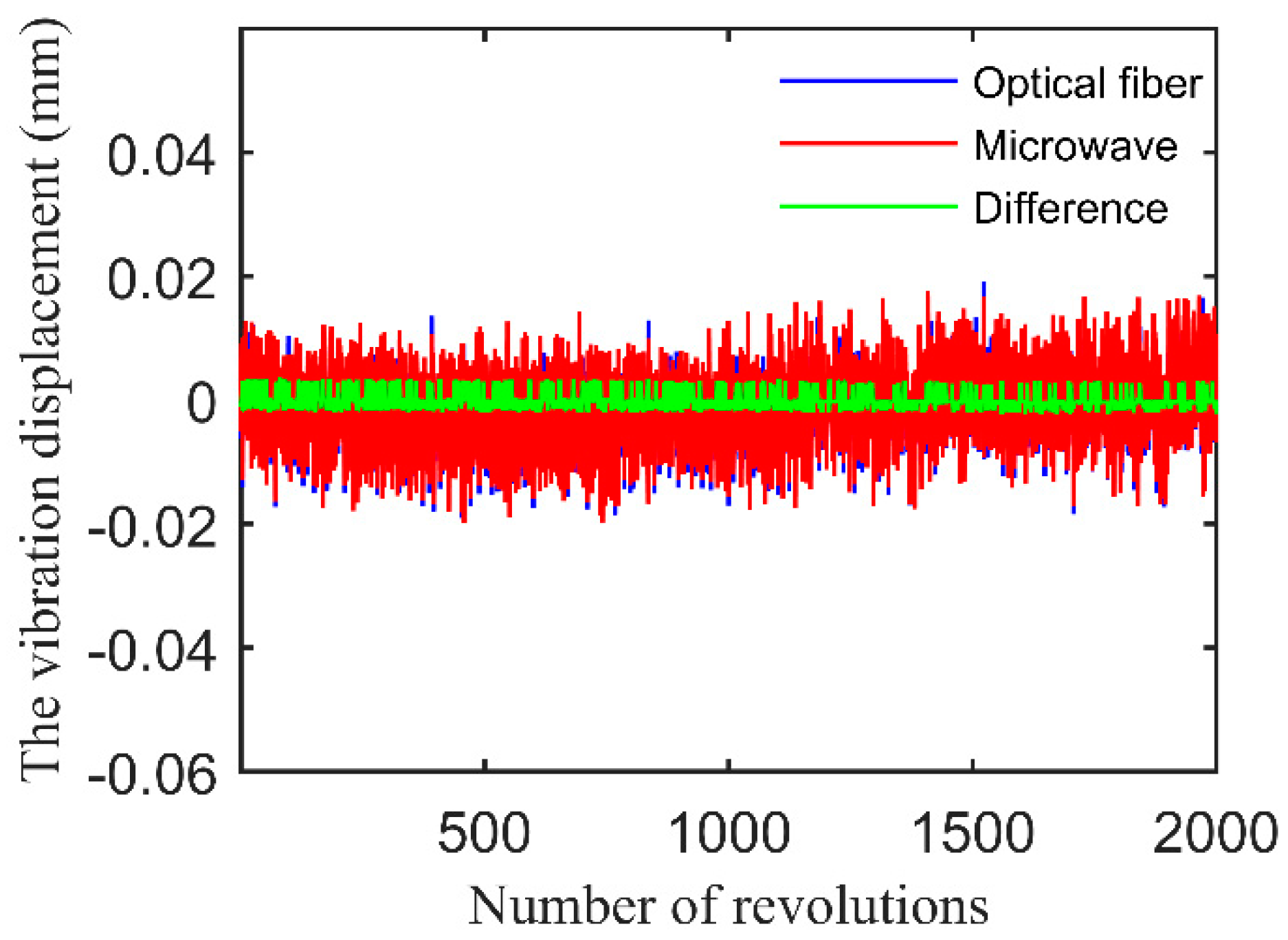
| Tip Clearance (mm) | Mean of Difference (mm) | Standard Deviation of Difference (mm) |
|---|---|---|
| 2 | 2.711 × 10⁻⁴ | 0.00127 |
| 3 | 3.159 × 10⁻⁴ | 0.00149 |
| 4 | 3.826 × 10⁻⁴ | 0.00191 |
© 2017 by the authors. Licensee MDPI, Basel, Switzerland. This article is an open access article distributed under the terms and conditions of the Creative Commons Attribution (CC BY) license (http://creativecommons.org/licenses/by/4.0/).
Share and Cite
Zhang, J.; Duan, F.; Niu, G.; Jiang, J.; Li, J. A Blade Tip Timing Method Based on a Microwave Sensor. Sensors 2017, 17, 1097. https://doi.org/10.3390/s17051097
Zhang J, Duan F, Niu G, Jiang J, Li J. A Blade Tip Timing Method Based on a Microwave Sensor. Sensors. 2017; 17(5):1097. https://doi.org/10.3390/s17051097
Chicago/Turabian StyleZhang, Jilong, Fajie Duan, Guangyue Niu, Jiajia Jiang, and Jie Li. 2017. "A Blade Tip Timing Method Based on a Microwave Sensor" Sensors 17, no. 5: 1097. https://doi.org/10.3390/s17051097
APA StyleZhang, J., Duan, F., Niu, G., Jiang, J., & Li, J. (2017). A Blade Tip Timing Method Based on a Microwave Sensor. Sensors, 17(5), 1097. https://doi.org/10.3390/s17051097