A New Input Device for Spastics Based on Strain Gauge


Abstract
:1. Introduction
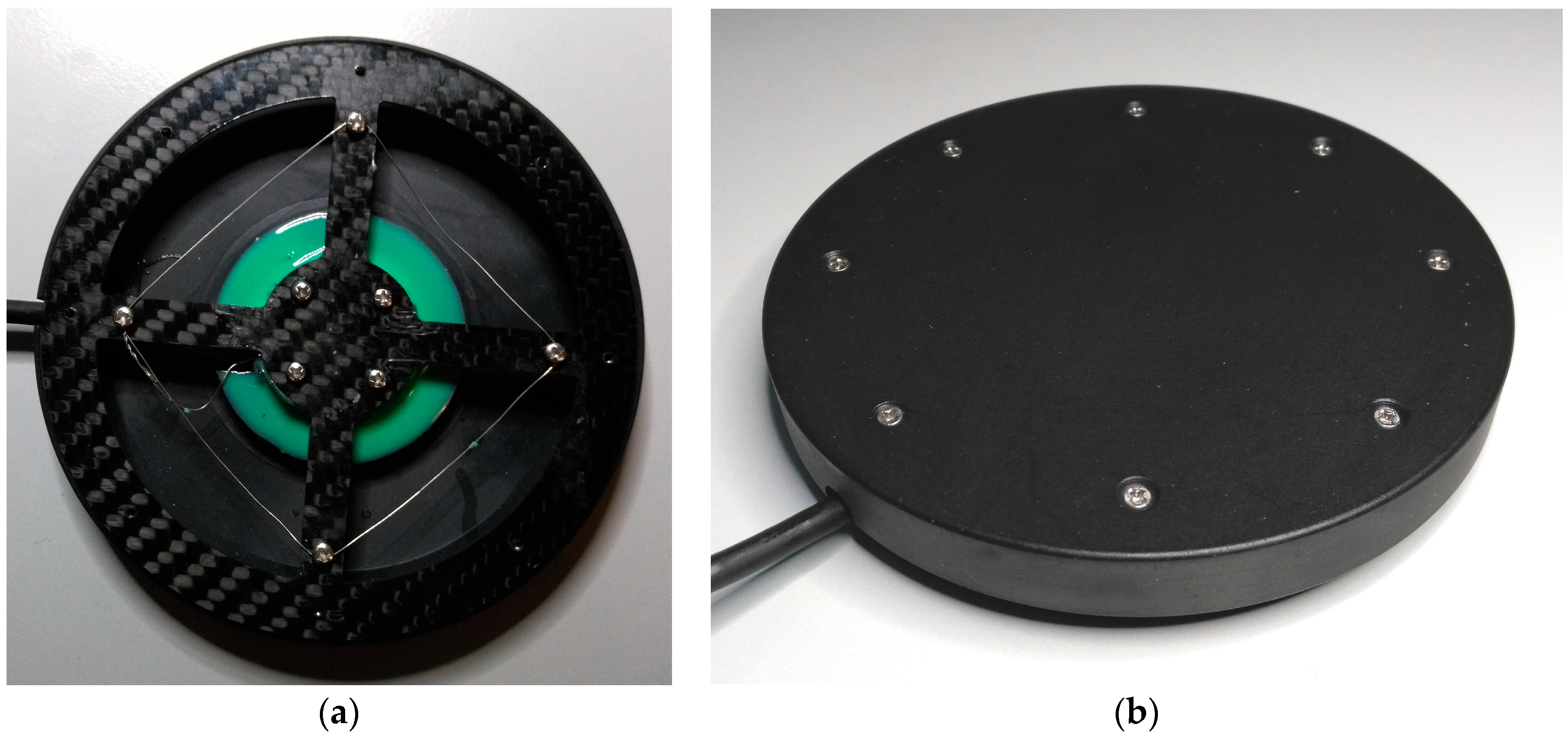
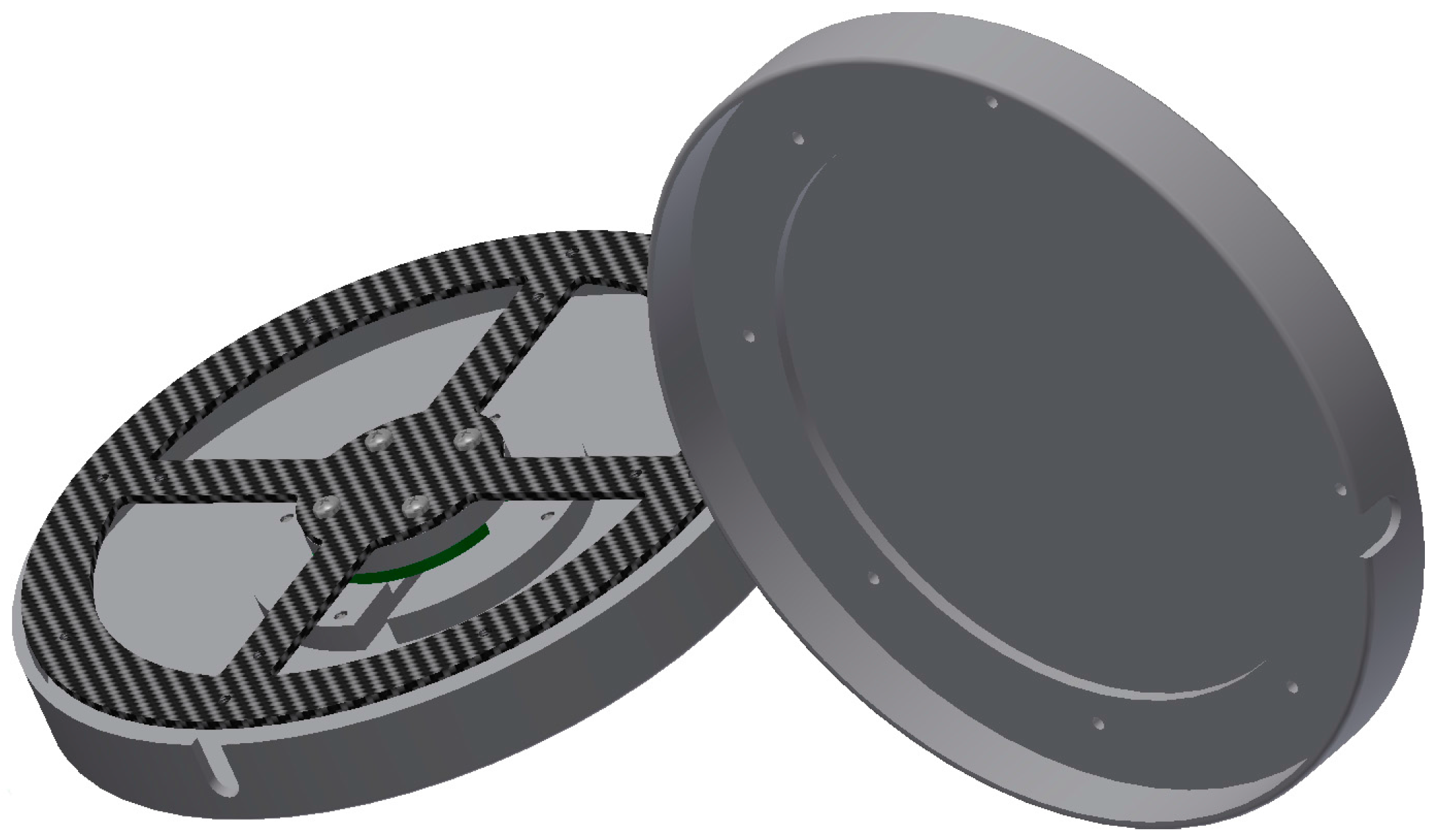
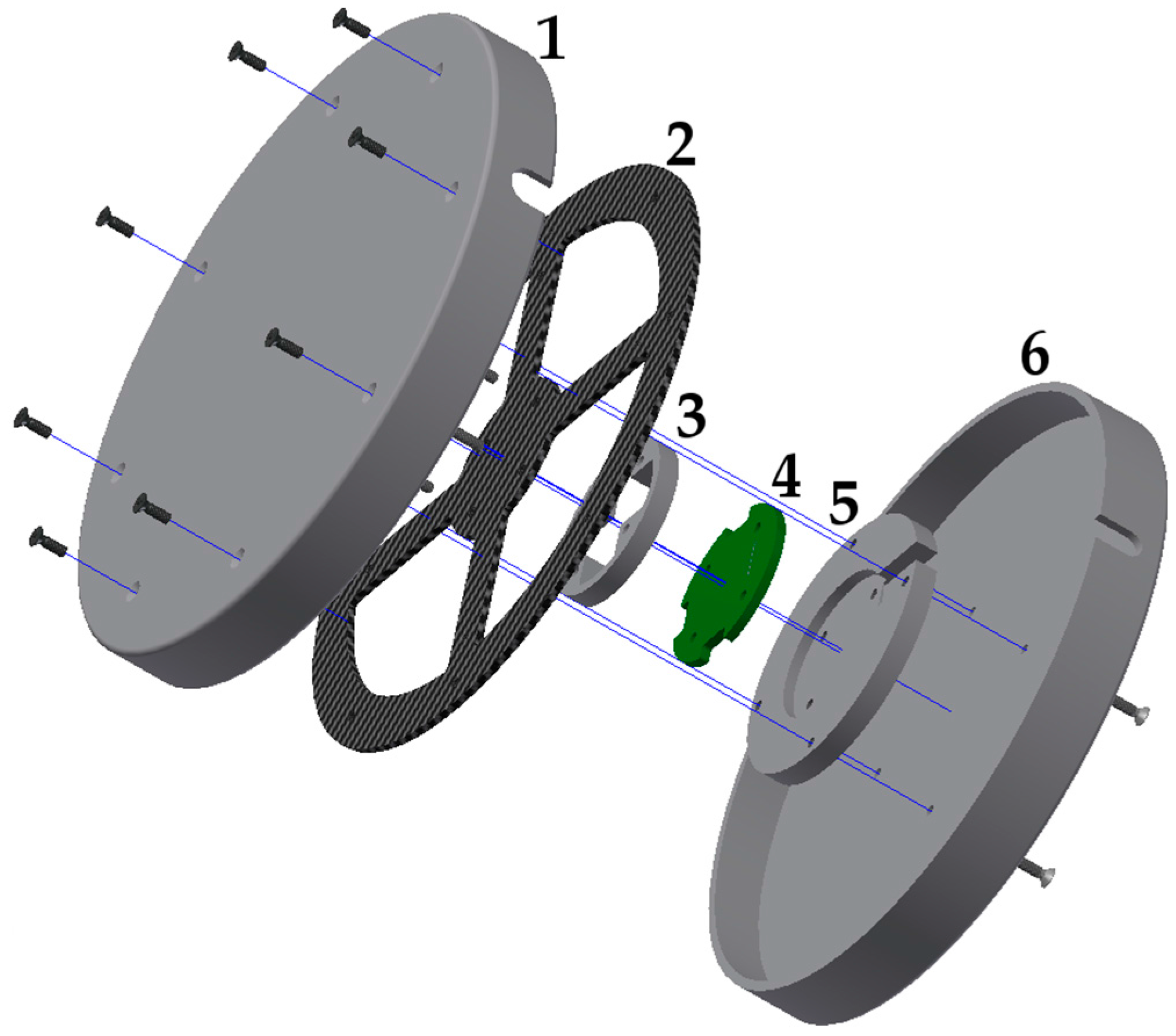
- The sensor’s flat disc-like design.
- The construction and shape of the movement carrier constructed using carbon fiber reinforced composite (CFRP).
- The movement carrier’s highly precise ability to return to its original position after being deflected.
- The software algorithm designed to adapt the sensor to a user’s own range of strength and motion.
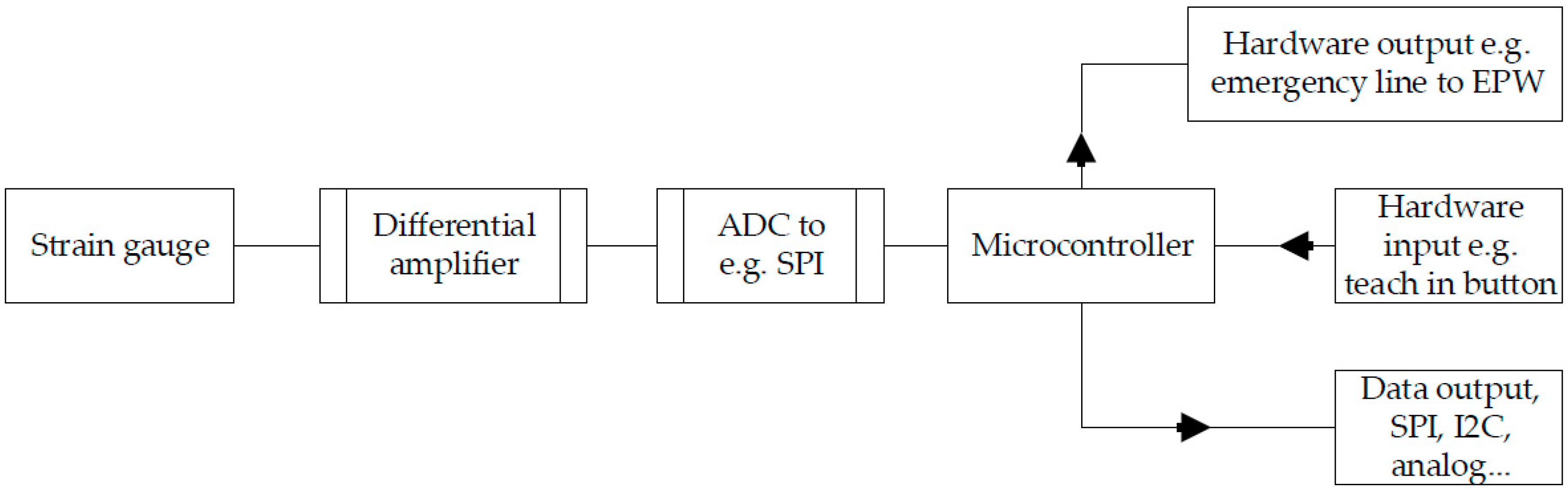
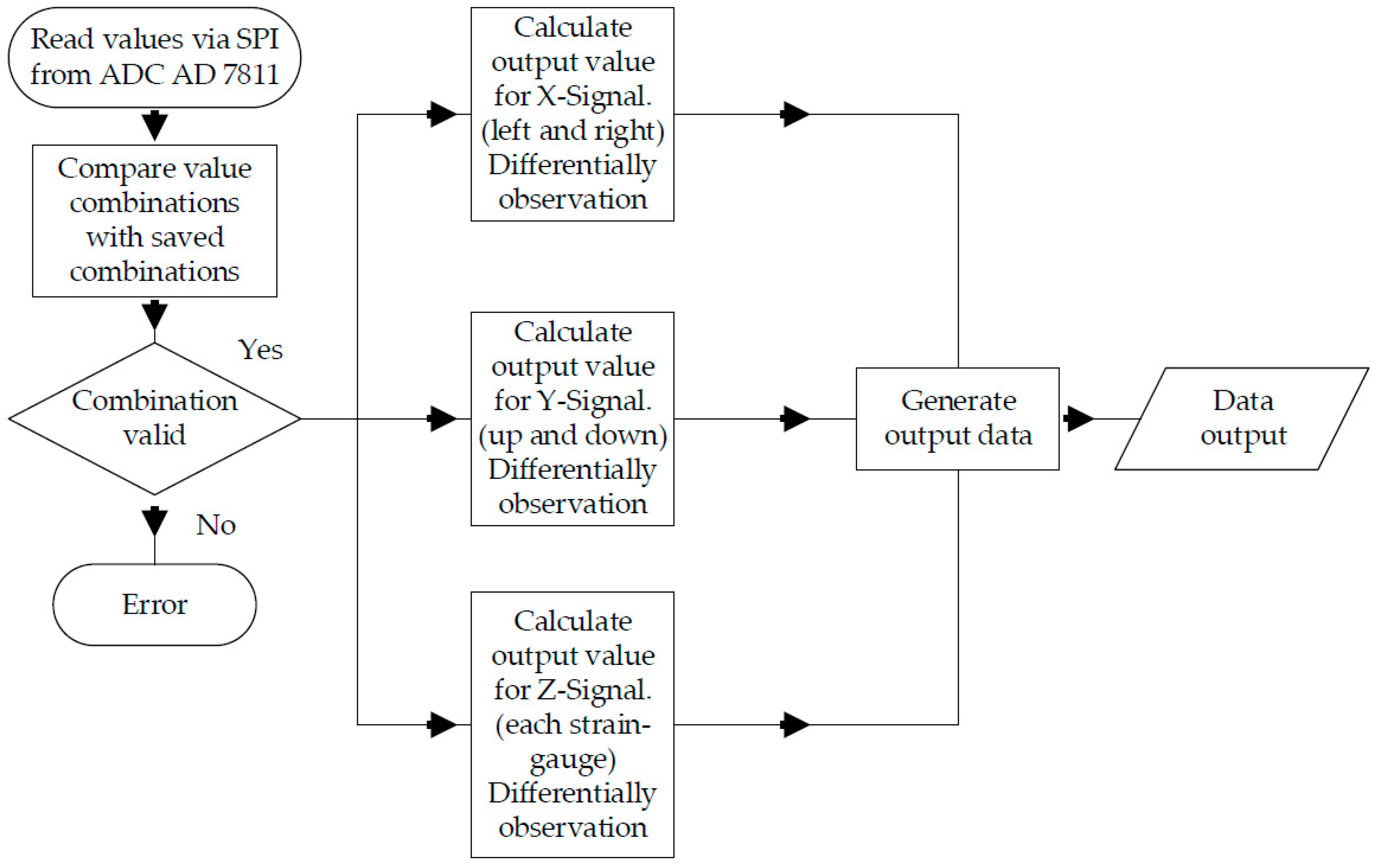
- The differential processing of measurements for plausibility checks to increase user safety.
- The sensor’s range of sensitivity between 0.05 N and 25 N.
- The sensor’s unsusceptibility to excess strain (e.g., in case of spasms, it withstands loads up to 1400 N).
2. Hardware of the SGD
2.1. Basic Construction
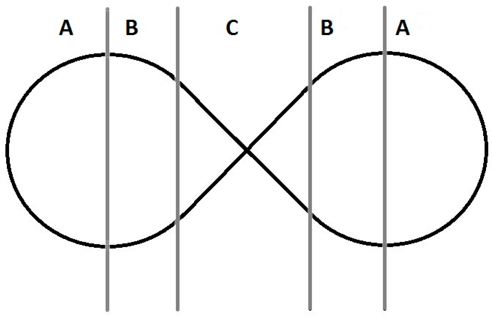
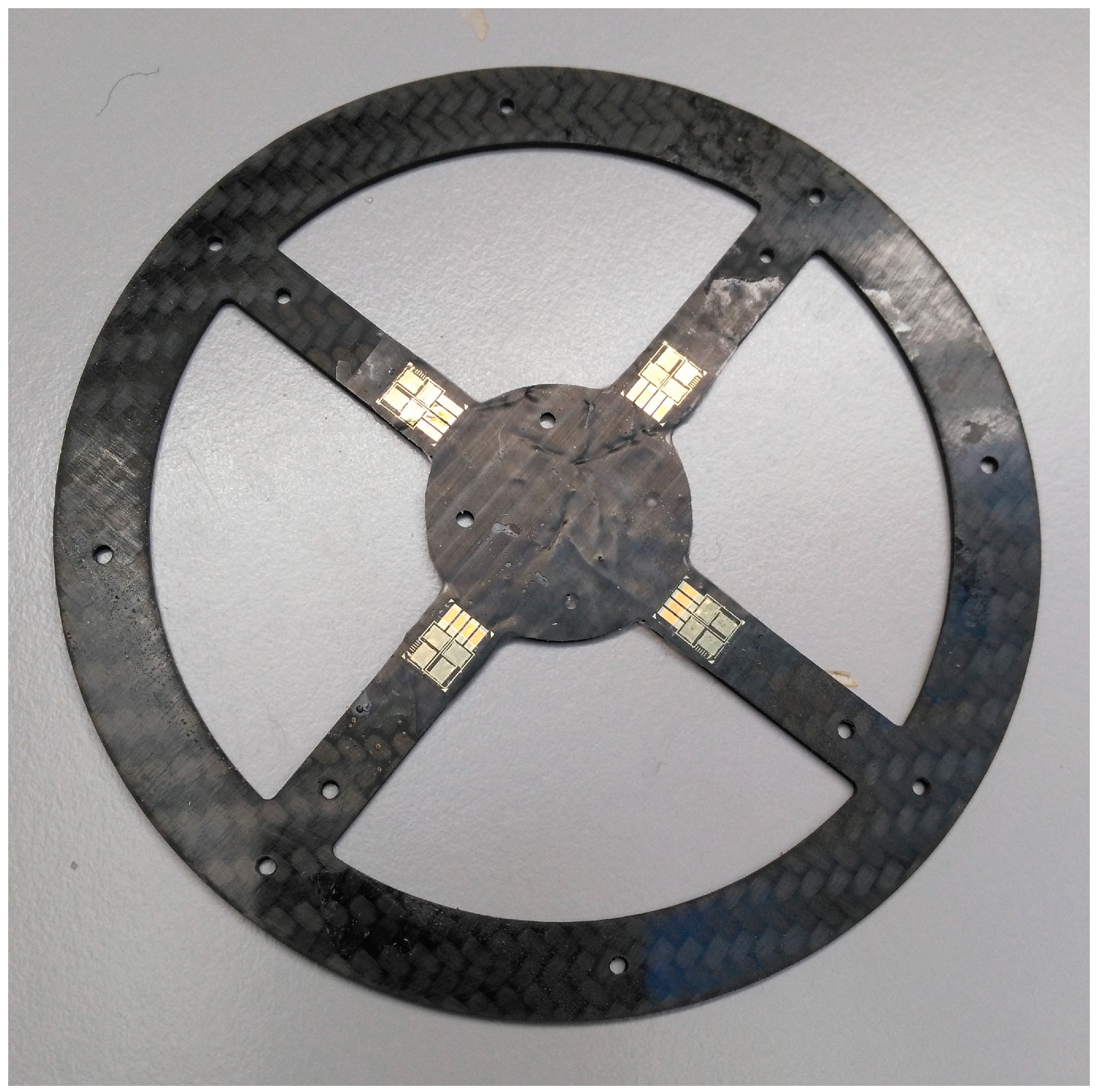
2.2. CFRP Carrier
2.3. Circuit Board and Microcontroller
2.4. Different Versions
3. Sensor Operations
3.1. Basics
| Measured neutral value; | |
| Measured value right strain gauges at t = 1; | |
| Measured value left strain gauges at t = 1; | |
| Output x-value to the microcontroller; | |
3.2. Plausibility Check
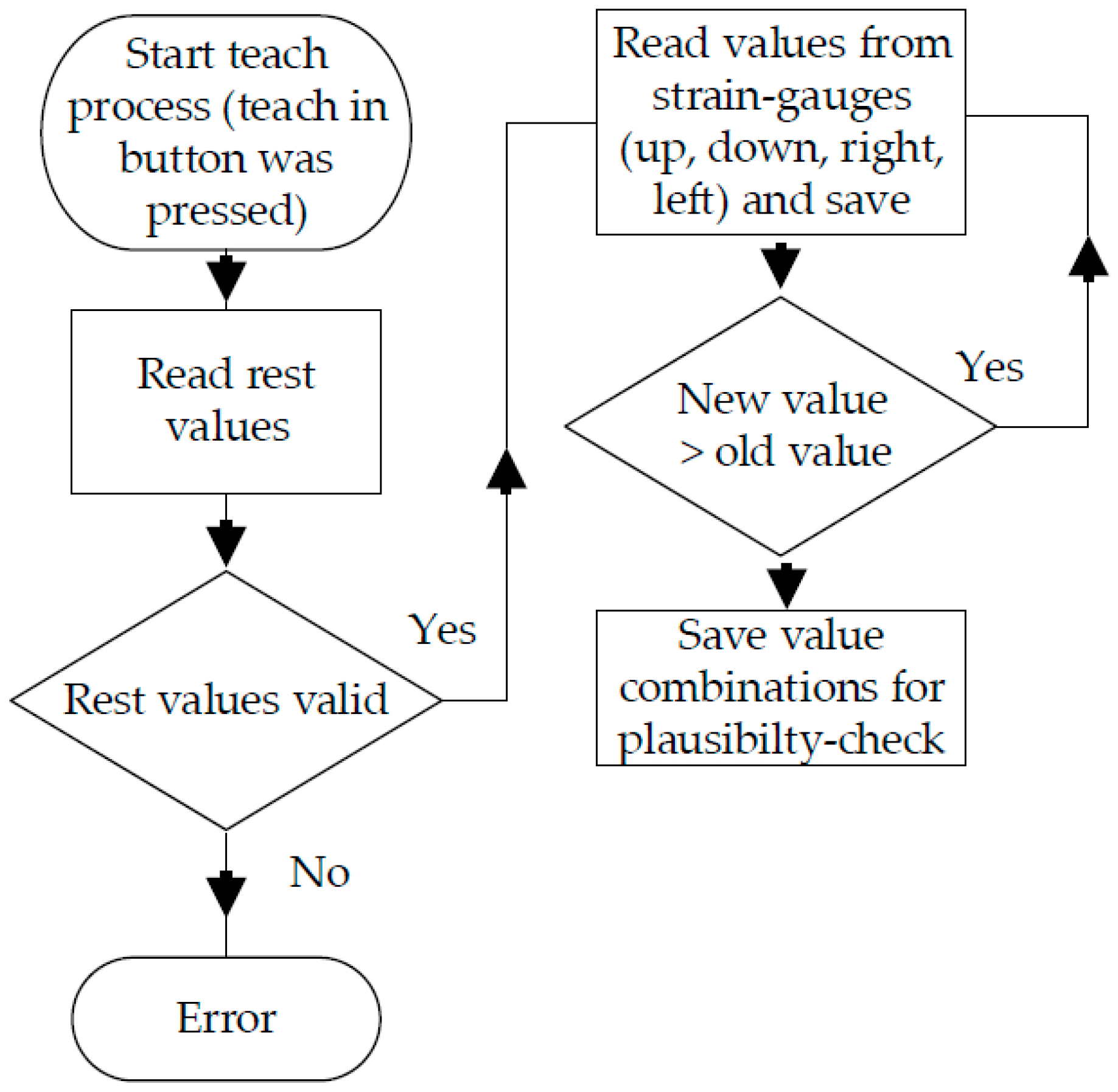
3.3. Individual Adjustment of the SGD
| Maximum right direction; | |
| Calculated factor see Table 3; | |
| Example value to the right; | |
| Digital output value; | |
| Digital output; |
3.4. Software
4. Results and Discussion
5. Conclusions
Author Contributions
Conflicts of Interest
References
- Buchhold, N.; Baumgartner, C. A New, Adaptable, Optical High-Resolution 3-Axis Sensor. Sensors 2017, 17, 254. [Google Scholar] [CrossRef] [PubMed]
- Hu, X.; Afsharipour, B.; Rymer, W.Z.; Suresh, N.L. Impairment of Muscle Force Transmission in Spastic-Paretic Muscles of Stroke Survivors. In Proceedings of the 2016 38th annual international conference of the IEEE Engineering in Medicine and Biology Society (EMBC), Orlando, FL, USA, 16–20 August 2016; pp. 6098–6101. [Google Scholar]
- Wolpaw, J.R.; Birbaumer, N.; Heetderks, W.J.; McFarland, D.J.; Peckham, P.H.; Schalk, G.; Donchin, E.; Quatrano, L.A.; Robinson, C.J.; Vaughan, T.M. Brain-computer interface technology: A review of the first international meeting. IEEE Trans. Rehabil. Eng. Publ. 2000, 8, 164–173. [Google Scholar] [CrossRef]
- Kim, K.-N.; Ramakrishna, R.S. Vision-Based Eye-Gaze Tracking for Human Computer Interface. In Proceedings of the IEEE SMC’99 Conference on Systems, Man and Cybernetics, Tokyo, Japan, 12–15 October 1999. [Google Scholar]
- Malkin, J.; House, B.; Bilmes, J. Control of Simulated Arm with the Vocal Joystick. In Proceedings of the CHI 2007 Workshop on Striking a C [h] ord: Vocal Interaction in Assistive Technologies, Games, and More, San Jose, CA, USA, 28 April–3 May 2007. [Google Scholar]
- House, B.; Malkin, J.; Bilmes, J. The VoiceBot: A Voice Controlled Robot Arm. In Proceedings of the SIGCHI Conference on Human Factors in Computing Systems, Boston, MA, USA, 4–9 April 2009; pp. 183–192. [Google Scholar]
- Buchhold, N. Apparatus for Controlling Peripheral Devices through Tongue Movement, and Method of Processing Control Signals. U.S. Patent 5,460,186 A, 24 October 1995. [Google Scholar]
- Kim, J.; Park, H.; Ghovanloo, M. Tongue-Operated Assistive Technology with Access to Common Smartphone Applications via Bluetooth Link. Conf. Proc. IEEE Eng. Med. Biol. Soc. 2012, 2012, 4054–4057. [Google Scholar] [PubMed]
- Martens, C.; Ruchel, N.; Lang, O.; Ivlev, O.; Graser, A. A friend for assisting handicapped people. IEEE Robot. Autom. Mag. 2001, 8, 57–65. [Google Scholar] [CrossRef]
- Huntemann, A.; Demeester, E.; Poorten, E.V.; van Brussel, H.; Schutter, J. Probabilistic Approach to Recognize Local Navigation Plans by Fusing Past Driving Information with a Personalized User Model. In Proceedings of the IEEE International Conference on Robotics and Automation (ICRA), Karlsruhe, Germany, 6–10 May 2013; pp. 4376–4383. [Google Scholar]
- Kim, E.Y. Wheelchair navigation system for disabled and elderly people. Sensors 2016, 16, 1806. [Google Scholar] [CrossRef] [PubMed]
- Cooper, R.A.; Widman, L.M.; Jones, D.K.; Robertson, R.N.; Ster, J.F. Force sensing control for electric powered wheelchairs. IEEE Trans. Control Syst. Technol. 2000, 8, 112–117. [Google Scholar] [CrossRef]
- Kamentser, B.; Kamentser, E. Force Transducer with Co-Planar Strain Gauges. U.S. Patent 5,872,320, 16 February 1999. [Google Scholar]
- Manara, A.; Scofield, M.C.; Cheal, B. Sensor and Circuit Architecture for Three Axis Strain Gauge Pointing Device and Force Transducer. U.S. Patent 6,243,077, 5 June 2001. [Google Scholar]
- Nejedly, P.; Whitfield, D.W. Three Dimensional Strain Gage Transducer. U.S. Patent 4,217,569, 12 August 1980. [Google Scholar]
- Ma, J.; Song, A. Fast estimation of strains for cross-beams six-axis force/torque sensors by mechanical modeling. Sensors 2013, 13, 6669–6686. [Google Scholar] [CrossRef] [PubMed]
- Analog Devices Inc. AD623 (Rev. E). Available online: http://www.analog.com/media/en/technical-documentation/data-sheets/AD623.pdf (accessed on 1 January 2017).
- Analog Devices Inc. AD7811/AD7812 (Rev. C). Available online: http://www.analog.com/media/en/technical-documentation/data-sheets/AD7811_7812.pdf (accessed on 1 January 2017).
- Ehrenstein, G.W. Faserverbund-Kunststoffe: Werkstoffe, Verarbeitung, Eigenschaften, 2nd ed.; Hanser Verlag: München, Germany, 2006. [Google Scholar]
- Muscular Dystrophy Association Inc. Facts about Myotonic Muscular Dystrophy. Available online: https://www.mda.org/sites/default/files/publications/Facts_MMD_P-212_0.pdf (accessed on 1 January 2017).
- Dynamic Controls. The DX2 System—Dynamic Controls. Available online: https://dynamiccontrols.com/en/dealers/products/dx2/the-dx2-system (accessed on 1 January 2017).
- Thorp, E.B.; Abdollahi, F.; Chen, D.; Farshchiansadegh, A.; Lee, M.-H.; Pedersen, J.P.; Pierella, C.; Roth, E.J.; Seanez Gonzalez, I.; Mussa-Ivaldi, F.A. Upper Body-Based Power Wheelchair Control Interface for Individuals With Tetraplegia. IEEE Trans. Neural Syst. Rehabil. Eng. Publ. 2016, 24, 249–260. [Google Scholar] [CrossRef] [PubMed]


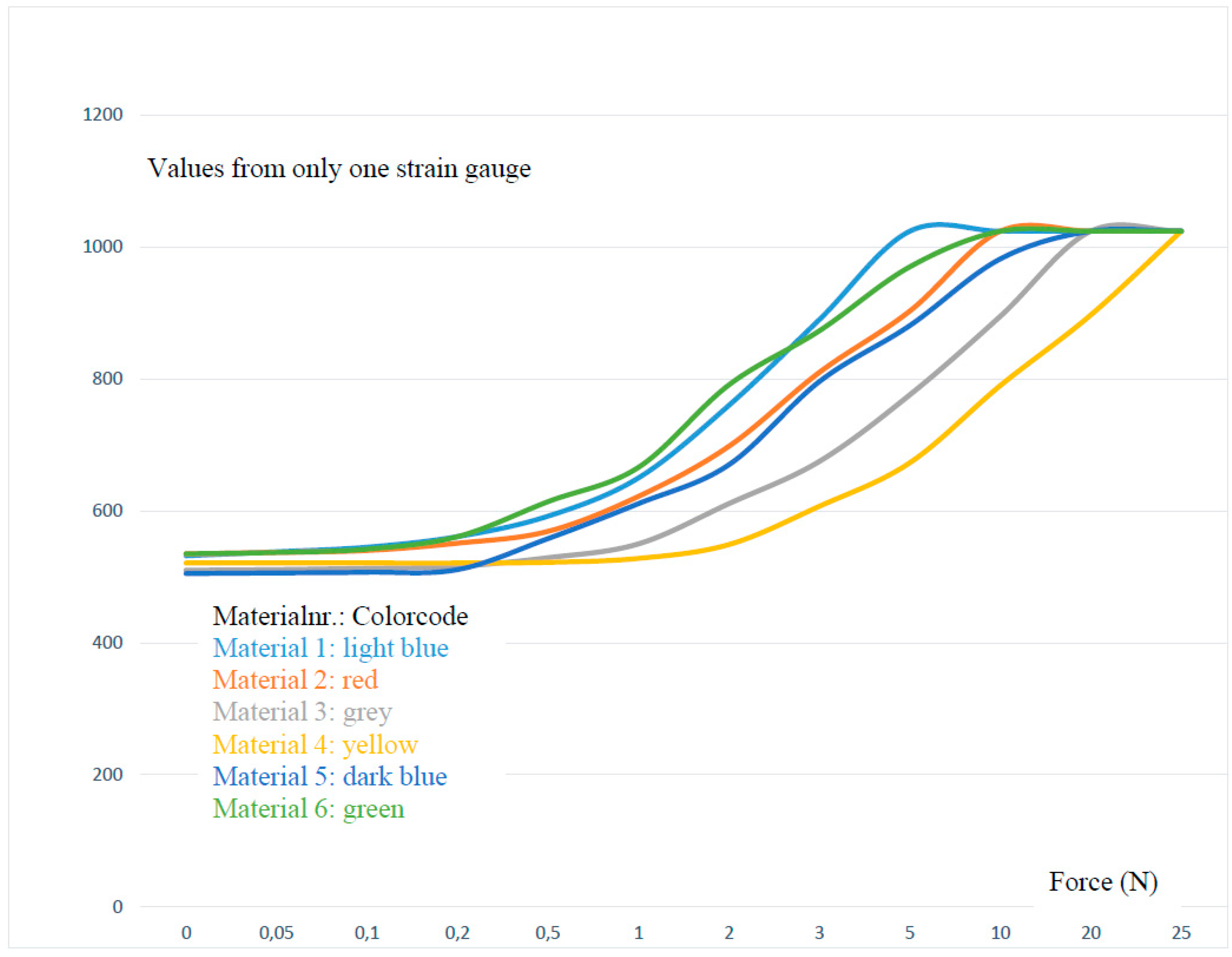
| Test Series; Force (N) Disc Diameter of 120 mm Mat. (Material) | 0 | 0.05 | 0.1 | 0.2 | 0.5 | 1 | 2 | 3 | 5 | 10 | 20 | 25 |
|---|---|---|---|---|---|---|---|---|---|---|---|---|
| Mat. 1 CFRP 0.45 mm non silicon rubber | 532 | 538 | 545 | 561 | 592 | 650 | 760 | 890 | 1024 | 1024 | 1024 | 1024 |
| Mat. 2 CFRP 0.90 mm non silicon rubber | 535 | 537 | 540 | 551 | 569 | 622 | 698 | 810 | 903 | 1024 | 1024 | 1024 |
| Mat. 3 CFRP 1.30 mm non silicon rubber | 510 | 511 | 513 | 516 | 529 | 550 | 611 | 675 | 776 | 895 | 1024 | 1024 |
| Mat. 4 CFRP 2.00 mm non silicon rubber | 521 | 521 | 521 | 521 | 522 | 528 | 549 | 607 | 673 | 790 | 897 | 1024 |
| Mat. 5 CFRP 0.90 mm silicon rubber shore 20 | 505 | 506 | 507 | 511 | 558 | 611 | 670 | 796 | 881 | 982 | 1024 | 1024 |
| Mat. 6 CFRP 0.45 mm silicon rubber shore 30 | 535 | 537 | 542 | 561 | 614 | 666 | 791 | 873 | 970 | 1024 | 1024 | 1024 |
| Material | CFRP Thickness | Silicon Rubber | Shore Hardness |
|---|---|---|---|
| Material 1 | 0.45 mm | no | none |
| Material 2 | 0.90 mm | no | none |
| Material 3 | 1.30 mm | no | none |
| Material 4 | 2.00 mm | no | none |
| Material 5 | 0.90 mm | yes | 20 |
| Material 6 | 0.45 mm | yes | 30 |
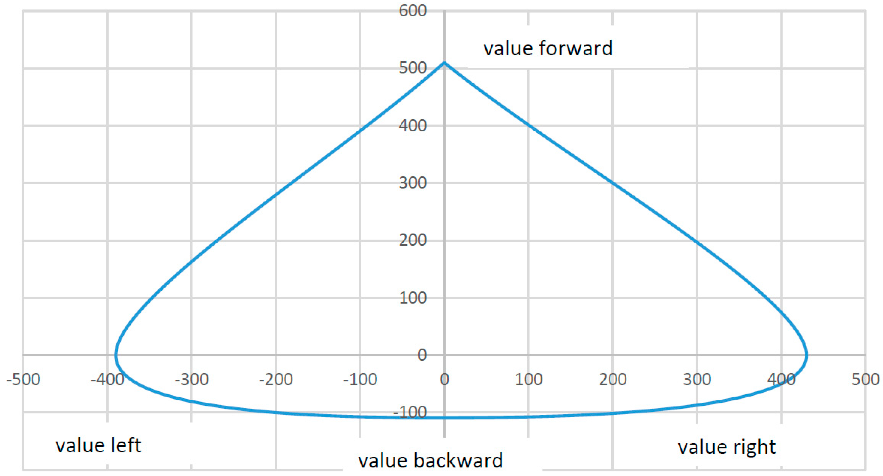
| Direction | Maximum Values | Approximate Force |
|---|---|---|
| forward | 510 | 18.4 N |
| backward | 109 | 2.1 N |
| left | 390 | 11 N |
| right | 430 | 14.2 N |
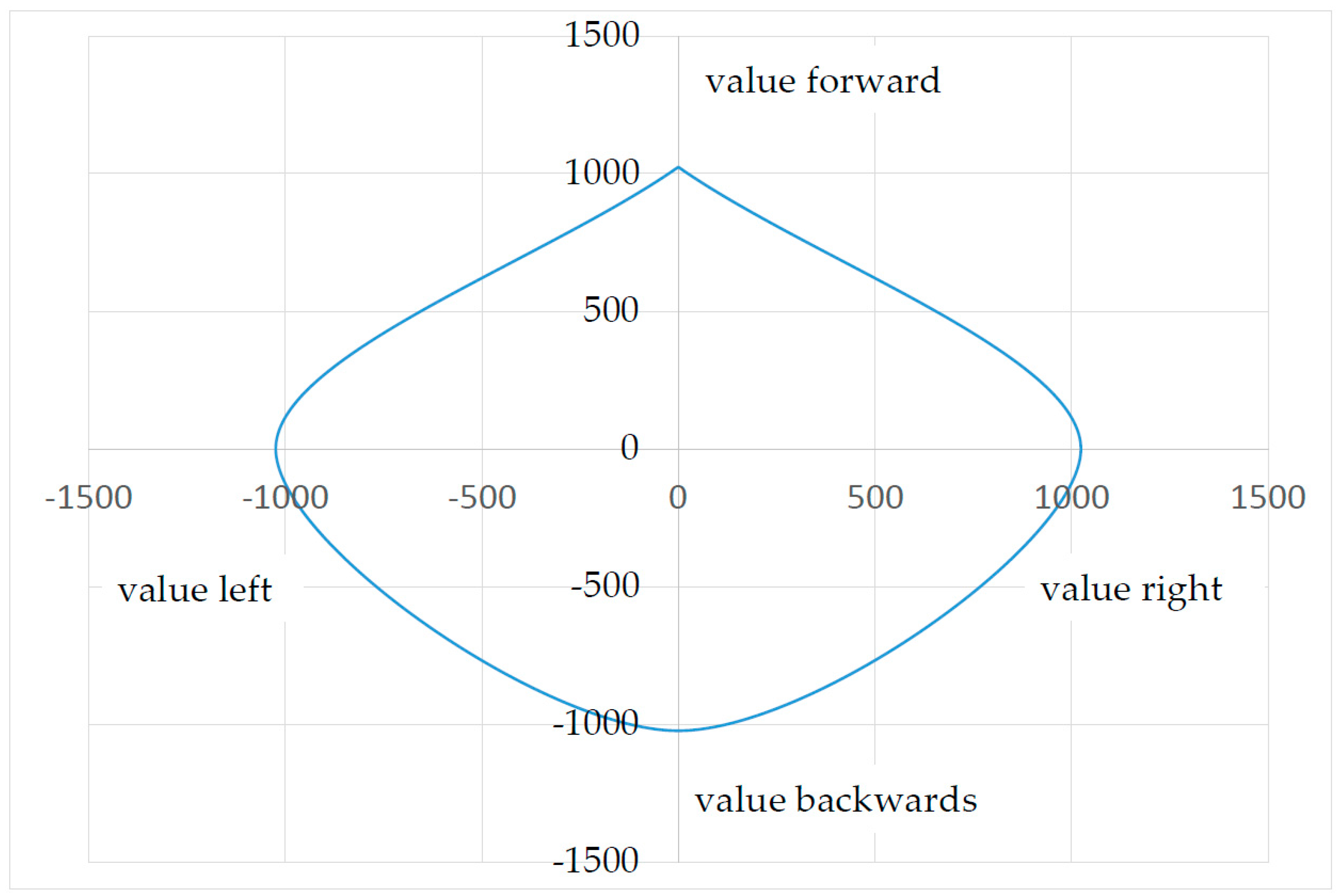
| Direction to | Maximum | Factor | Calculated Output Values |
|---|---|---|---|
| forward | 510 | 2007 | 1024 |
| back | 109 | 9394 | 1024 |
| left | 390 | 2626 | 1024 |
| right | 430 | 2381 | 1024 |
| Temperature °C | Resting Values Forward | Resting Values Backward | Resting Values Right | Resting Values Left |
|---|---|---|---|---|
| −30 | 509 | 499 | 502 | 504 |
| −20 | 509 | 499 | 502 | 504 |
| −10 | 510 | 499 | 502 | 504 |
| 0 | 510 | 499 | 502 | 504 |
| 10 | 510 | 499 | 502 | 504 |
| 20 | 510 | 499 | 502 | 504 |
| 30 | 510 | 499 | 502 | 504 |
| 40 | 510 | 499 | 502 | 504 |
| 60 | 511 | 500 | 502 | 504 |
| 70 | 511 | 500 | 502 | 505 |
| 80 | 510 | 500 | 502 | 505 |
| Temperature °C | Resting Values Forward | Resting Values Backward | Resting Values Right | Resting Values Left |
|---|---|---|---|---|
| −30 | 829 | 182 | 769 | 231 |
| −20 | 829 | 182 | 769 | 231 |
| −10 | 829 | 182 | 770 | 231 |
| 0 | 829 | 182 | 770 | 231 |
| 10 | 829 | 182 | 770 | 231 |
| 20 | 829 | 182 | 770 | 231 |
| 30 | 829 | 183 | 770 | 231 |
| 40 | 829 | 183 | 770 | 231 |
| 60 | 829 | 183 | 770 | 231 |
| 70 | 830 | 183 | 770 | 231 |
| 80 | 829 | 183 | 771 | 231 |
| Strain (N) | Resting Values Forward | Resting Values Backward | Resting Values Right | Resting Values Left |
|---|---|---|---|---|
| Resting Values | 510 | 499 | 502 | 504 |
| forward 25 | 510 | 499 | 502 | 504 |
| forward 100 | 510 | 499 | 502 | 504 |
| forward 500 | 511 | 499 | 502 | 504 |
| forward 1400 | 511 | 499 | 502 | 504 |
| backward 25 | 510 | 499 | 502 | 504 |
| backward 100 | 510 | 499 | 502 | 504 |
| backward 500 | 509 | 498 | 502 | 504 |
| backward 1400 | 509 | 498 | 502 | 504 |
| right 25 | 510 | 499 | 502 | 504 |
| right 100 | 510 | 499 | 502 | 504 |
| right 500 | 510 | 499 | 503 | 503 |
| right 1400 | 510 | 499 | 503 | 503 |
| left 25 | 510 | 499 | 502 | 504 |
| left 100 | 510 | 499 | 502 | 505 |
| left 500 | 510 | 499 | 502 | 505 |
| left 1400 | 510 | 499 | 502 | 505 |
© 2017 by the authors. Licensee MDPI, Basel, Switzerland. This article is an open access article distributed under the terms and conditions of the Creative Commons Attribution (CC BY) license (http://creativecommons.org/licenses/by/4.0/).
Share and Cite
Buchhold, N.; Baumgartner, C. A New Input Device for Spastics Based on Strain Gauge. Sensors 2017, 17, 880. https://doi.org/10.3390/s17040880
Buchhold N, Baumgartner C. A New Input Device for Spastics Based on Strain Gauge. Sensors. 2017; 17(4):880. https://doi.org/10.3390/s17040880
Chicago/Turabian StyleBuchhold, Niels, and Christian Baumgartner. 2017. "A New Input Device for Spastics Based on Strain Gauge" Sensors 17, no. 4: 880. https://doi.org/10.3390/s17040880
APA StyleBuchhold, N., & Baumgartner, C. (2017). A New Input Device for Spastics Based on Strain Gauge. Sensors, 17(4), 880. https://doi.org/10.3390/s17040880