1. Introduction
The analysis of the SNR is very important to determine the variance of the radar cross section or reflectivity, and therefore, to assess the system’s capability and accuracy to measure geophysical parameters. The accuracy of radar scatterometric measurements from space was first addressed in [
1], where two different effects were analyzed: the bias due to a lack of precise knowledge of the exact value of the system’s parameters, and the random fluctuations of the measured signal. While the bias can be compensated for through appropriate instrument calibration, the random fluctuations of the signal (
speckle noise [
2]) can only be reduced by averaging. In [
1], it was considered that both the signal and the system noise follow Gaussian statistics, that is, the received signal is purely incoherent.
GNSS-R is a field that emerged in 1988 with the proposal of the multi-static GNSS-based scatterometry technique for remote sensing [
3]. In 1993, the PAssive Reflectometry and Interferometry System (PARIS) concept was proposed in order to do mesoscale altimetric measurements using the signals of opportunity provided by the GNSS satellites [
4]. Due to the forward scattering geometry and the surface scattering properties, the reflected signal may not always obey the Gaussian statistics assumed in [
1]. In such cases, the statistics of the reflected field follow a Hoyt distribution, which describes a Gaussian field plus a coherent component [
5]. In that scenario, a new scatterometric analysis must be performed in order to estimate the scatterometric accuracy of GNSS-R techniques.
The first GNSS-R scatterometric analysis was performed in 2001 [
6], where a statistical analysis of the scatterometric SNR was presented, determining the accuracy of the surface height retrieval and the minimum number of samples required to estimate wind speed from a space-borne platform using cGNSS-R. Therein, the power spectrum of the sea-surface-reflected waveform was also introduced, which is of high importance in this analysis. However, this spectrum was derived assuming that there was no coherent component, which validates the expression only for rough sea surfaces. In 2004 and 2006, a detailed study regarding the correlation function of the sea surface GNSS-R waveform was presented, including a stochastic voltage model of the reflected waveforms and their autocorrelation functions [
7,
8]. In 2011, the scatterometric accuracy of a PARIS-like instrument using the iGNSS-R approach was presented [
9]. In all those studies, a Gaussian model like the one in [
1] was assumed, because experimental evidence had confirmed that the sea-surface scattered signals follow complex Gaussian statistics.
The new data obtained from the UK TDS-1 satellite have shown that while the Gaussian statistics is a valid model for the sea surface scattered signals, it is not satisfactory for surfaces such as flat land areas, and in particular wetlands, sea-ice, and lakes [
10]. For such surfaces the retrieved Delay-Doppler Map (DDM)s show a “K-shape” feature, as shown in [
11], which indicates a presence of the coherent component, requiring the use of a Hoyt distribution to describe the statistics of the scattered signals. Following this evidence, this work extends the scatterometric analysis performed in [
9] to the cGNSS-R case, and includes the presence of the coherent component in the scattered signals that was not considered in previous works.
This paper starts with a definition of the signal model for both cGNSS-R and iGNSS-R cases. Then, the correlation peak statistics, which is the interesting one in the scatterometric mode, is analyzed for the GNSS case. Subsequently the same analysis is performed to the GNSS-R case, including the effect of non-coherent integration. Later, the variability of the correlation peak is computed. Simulations analyzing the performance of the UK TDS-1 and GEROS-ISS mission in terms of SNR and correlation peak variability are performed. This paper ends with a discussion and a concluding section highlighting the main achievements.
3. Correlation Peak Statistics in GNSS and Squaring Loss Paradox
The analysis of the correlation peak statistics has been widely explored in the GNSS literature [
24,
25,
26,
27,
28]. The fundamental operation in a GNSS signal acquisition system is the cross-correlation of the digitized received signal with a clean replica of the satellite code (matched filter) in order to obtain the so-called waveform, see Equation (
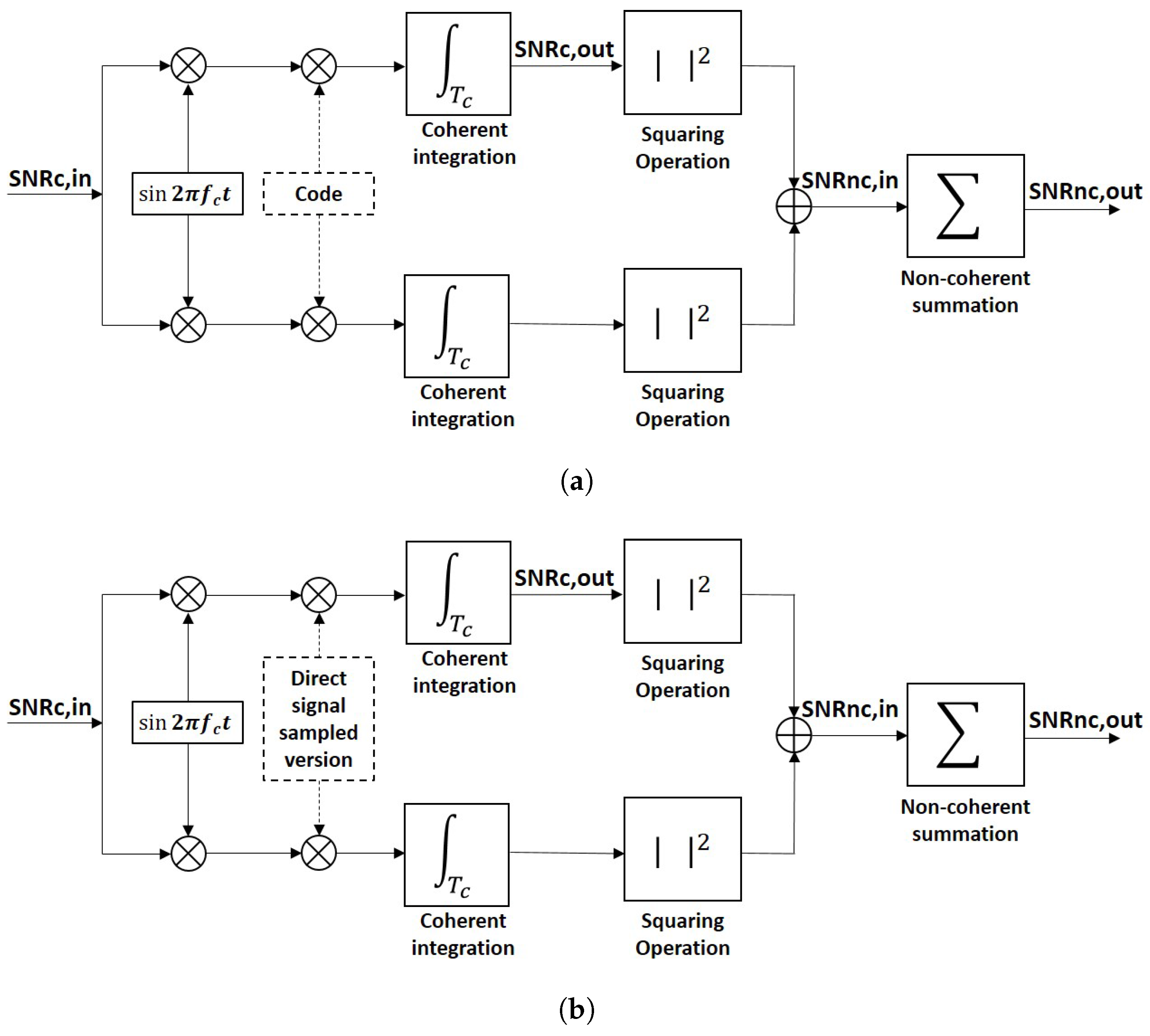
1), which is the same computational operation that is performed in a conventional GNSS-R receiver. This computation is also known as coherent integration, and it can last up to 20 ms, which is the duration of a navigation bit. Longer coherent integration times can be always applied after compensating for the navigation bit sign change. After coherent integration, non-coherent integration is performed, which consists of summing the waveforms obtained in power units to improve the visibility or detectability of the satellite presence. Non-coherent integration requires a squaring operation which changes the statistics of the obtained samples, and therefore, leads to a redefinition of the resulting SNR.
Figure 1a shows a typical block diagram of a coherent or I/Q detector. It is possible to introduce four different definitions of the SNR, but they correspond, in fact, to two. The first one is the
, which is the SNR before correlation with the clean replica of the satellite code, or pre-correlation SNR. It is always negative since GNSS signals are below the noise level, unless a very high directivity antenna is used to acquire them. The second one is the
, which is the SNR after correlation with the clean replica of the satellite code. It is related to the
by the signal’s bandwidth times the coherent integration time. Basically, the thermal noise bandwidth is reduced in the coherent integration process, letting the signal rise above the new thermal noise level. The third one is the
, which is the SNR resulting from a non-coherent detection scheme where no phase information is available. The
is related to the
by the squaring-loss parameter [
29]. The last one is the
, which is the SNR after the non-coherent integration/averaging.
In traditional GNSS applications, the received signal is formed by a coherent or LOS component and the thermal noise. The coherent component is a deterministic signal, and the thermal noise is modeled as a complex Gaussian random variable with zero mean and variance/power
. In this case, the incoherent scattered component term is not present since there is no scattering process involved. To analyze the
, it is necessary to concentrate on the correlation peak, where the signal’s amplitude is the largest. One way to determine the
is by applying the detectability criterion [
30], which is based on a comparison of the signal power against its variability (noise power)
where
is a function with a subscript which stands for the signal (
S) plus noise (
N) components, and
is a function with a subscript which indicates that stands only for the noise components.
The detectability criterion involves the use of the signal’s mean value which is divided it by its standard deviation. It is an amplitude/voltage signal-to-noise ratio if the function
is defined in Volts [V] units, and it is a power signal-to-noise ratio if the same function is defined in Volts squared [V
] units [
31]. If it is applied when the samples are squared, which is the Volts squared case, the conventional SNR definition is obtained as:
where
A is the signal amplitude in [V],
stands for the signal (
S) power, and
for the thermal noise (
N) power.
As seen, in the computation of the traditional detectability criterion (
d), the signal power is measured at the waveform’s correlation peak (where both signal and noise components are present,
). The noise power is evaluated outside the waveform correlation peak (where the signal is not present,
N). However, in the squaring process, the properties of the signal change. Before squaring, the signal’s variability at the correlation peak and at any other correlation lag is the same, since only zero-mean thermal noise is present. Conversely, after squaring, outside the correlation peak an exponential random variable is found (square of a complex Gaussian random variable), whereas at the correlation peak, a non-central
random variable emerges due to the presence of the LOS signal component. This means that the variability at lags outside the interval occupied by the main part of the ACF function is different from the one at the correlation peak. Consequently, the effect of the same noise is different depending on the correlation lag where it is analyzed. Therefore, its effect on the correlation peak cannot be studied when there is no signal presence, which could be done before squaring. At this point, the so-called “squaring-loss" parameter plays a role in the observed SNR, and a different detectability criterion (
) must be used to take into account the noise effect at the correlation peak [
32], which is
Comparing Equations (
10) to (
8), it can be seen that whereas the numerator remains the same, the denominator changes. The computation of
involves computing the correlation peak variability under the presence of both signal and noise terms, which is a more realistic approach. This detectability criterion can also be applied to estimate the
. In the particular example of Equation (
9), the result would be the same than the one obtained using Equation (
8), because before squaring the mean of the noise samples is zero, a fact that changes due to squaring. By specifying terms in Equation (
10) for the squaring case, the
and the
can be expressed in terms of the
[
31,
32,
33]:
where
is the effective number of averaged samples [
13,
34]. If
samples are independent, which is a valid approximation here because the signal term is deterministic, the variability at the correlation peak is due to thermal noise whose samples are independent by definition, and therefore
tends to
N, being
N the number of independent samples averaged. Although these equations are valid for the navigation case, the GNSS-R case adds an extra feature: the speckle noise due to the scattering [
2,
14]. This means that the variability of the correlation peak is not only due to thermal noise, but also due to the scattering process, and previous equations should be modified accordingly.
4. Correlation Peak SNR in cGNSS-R and iGNSS-R
Due to the low-power and high-phase noise of the GNSS reflected signals both cGNSS-R and iGNSS-R approaches tend to use ∼1 ms of coherent integration time and then apply the non-coherent summations/averaging, which means that they work with the power waveforms instead of the complex-value voltage waveforms. The power waveform,
, is defined as the absolute-value squared of the voltage waveform:
where
a stands for
c or
i, in order to distinguish between the conventional and interferometric techniques. Hence, the detectability criteria become, where mathematical details are in
Appendix A and
Appendix C,
where
, and it stands for the coherent reflected power,
, and it stands for the incoherent reflected power,
, and it stands for the cGNSS-R thermal noise power,
is the pre-correlation SNR or
for the direct signal,
is the pre-correlation SNR or
for the reflected signal, and:
where
is the post-correlation thermal SNR or
for the reflected signal in the cGNSS-R case,
is the signal to speckle noise ratio, and
is the equivalent post-correlation thermal SNR or
for the reflected signal in the iGNSS-R case.
The difference between taking into account the variability of the signal at its correlation peak or away from it is clearly seen by comparing with , and with . When the variability at the correlation peak is considered, the detectability criterion is degraded ( and ). Also, the cGNSS-R and iGNSS-R approaches can be compared using the detectability criteria. The comparison between and shows that the detectability criterion for the iGNSS-R is a degraded version of the cGNSS-R one. This occurs because for the iGNSS-R approach the thermal noise rises in comparison with the cGNSS-R approach due to the two extra noise terms to be considered. However, if , then . The same occurs when considering the and , since . Equally, if , then , and . There is another aspect that is related to the definition of the detectability criterion, which is that the mean noise level value in the iGNSS-R case is not subtracted at the correlation peak by using the one computed at lags away from the correlation peak. The remaining term is , but since , this term can be neglected.
The coherent, incoherent, and thermal noise powers presented above can be computed as [
18]
where
stands for the illuminated area,
for the radar cross-section at the incident
p polarization and reflected
q polarization,
where
,
k is the Boltzmann constant,
stands for the antenna temperature,
K,
F for the noise figure of the receiving chain, and
for the receiver’s equivalent noise temperature. If it is assumed that thermal noise is white, the dependence on
τ can be neglected and the thermal noise power is
.
The coherent component is defined only for
, which corresponds to the ACF function of the GNSS Pseudo-Random Noise (PRN) codes, and the radiation comes from the first Fresnel zone area. On the other side, the incoherent component exists for different values of
τ, which will depend on the surface roughness conditions. Note that increasing the transmitted power or the antenna gain does not improve the signal-to-speckle noise ratio (
), because the speckle noise, or also Rayleigh fading, is a multiplicative/scattering noise (self-noise) [
2]. Note that when the coherent component is negligible the
, which occurs in a backscattering geometry such as in Synthetic Aperture Radar (SAR) systems [
35]. Also, note that
for this case, because this SNR is defined as a power SNR. If the voltage signals are considered, the result of the
would be the well-known 5.56 dB for the speckle noise [
35], which corresponds to the ratio between the mean and the standard deviation of a Rayleigh random variable.
5. Effect of Non-Coherent Summations in the Detectability Criteria
Due to the low power, and consequently low SNR, of GNSS reflected signals, averaging or non-coherent summations of consecutive waveforms is needed to improve the quality of the data retrieved and reduce the degradation from the speckle noise. This is also known as non-coherent integration, and it is also the same procedure performed in conventional GNSS receivers as it was remarked in the last step of the signal processing flow chart in
Figure 1. Mathematically, non-coherent averaging of consecutive power waveforms is modeled as
where
stands for the power waveform,
n for the waveform index, and
N is the number of waveforms used in the summation. When non-coherent integration is applied, the variability of the signal is highly reduced, which helps to detect the waveform. This operation should theoretically improve the SNR by a factor of
, as stated in Equation (
11), when samples are independent. However, some airborne experimental data have shown that the improvement factor is sometimes smaller than that in the lags where the signal term is present, see for instance [
33,
34]. This fact is generally related to the platform’s height and speed, which are the parameters that determine the surface correlation time, since for airborne and space-borne conditions the surface can be considered frozen during the coherent integration time [
15]. The Van Cittert-Zernike theorem can be used to obtain a rough estimation of the surface correlation time, taking into account the wavelength, the platform’s speed and height, the shape of the illuminating signal, and the incidence angle [
8,
36]. If the estimated surface correlation time is larger than the coherent integration time, the speckle noise term will be correlated, and consequently samples will not be independent. Conversely, under spaceborne conditions, experimental data have shown that samples are practically uncorrelated [
37], which occurs because the platform is relatively faster. In other words, for spaceborne applications, the surface correlation time is close to 1 ms (coherent integration time) due to the receiving satellite orbit that determines the platform’s speed, whereas for airborne applications, the surface correlation time depends highly on the platform’s height and speed, whose parameters depend more on the aircraft used.
Since experimental spaceborne waveforms seem to be uncorrelated [
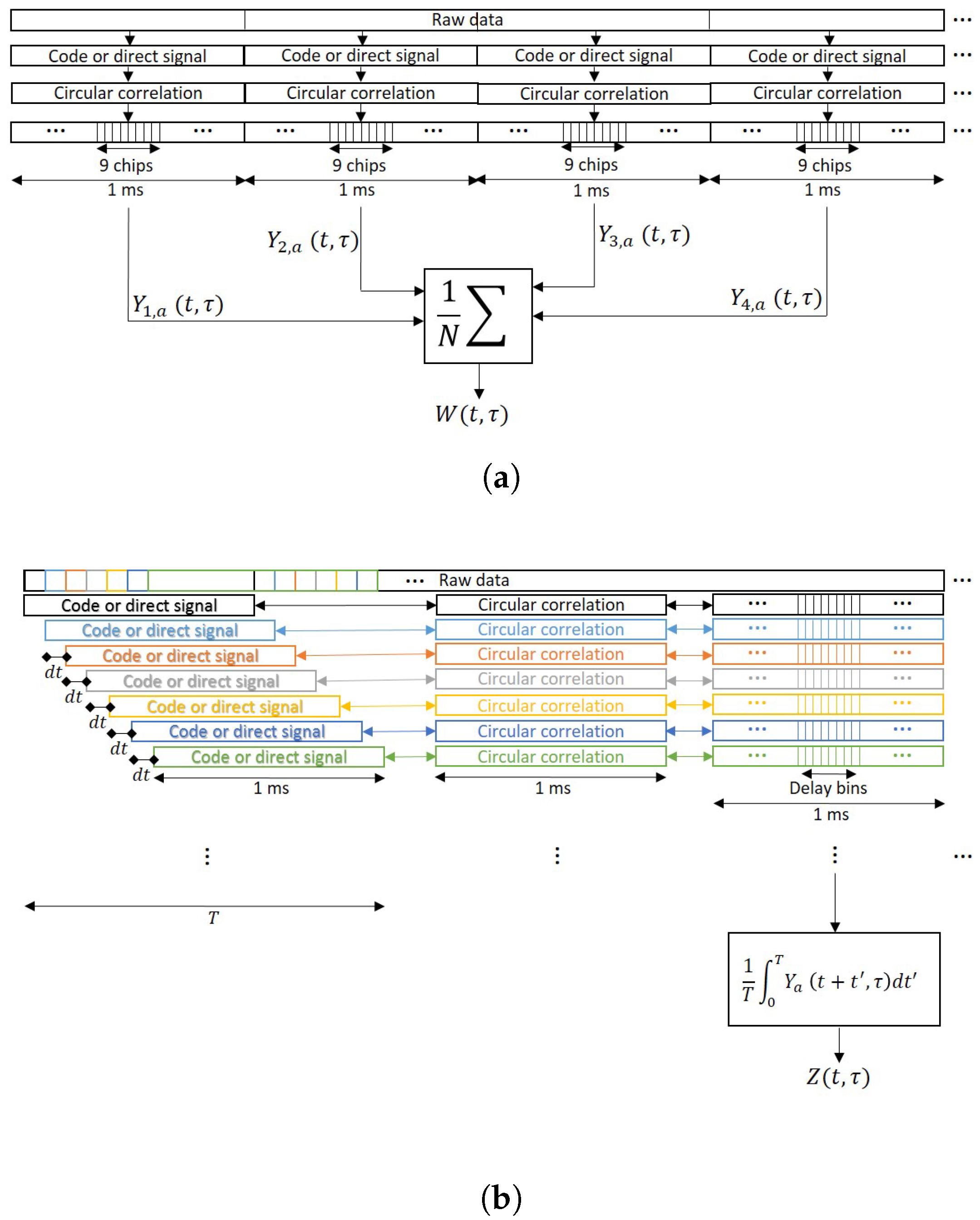
37], one may think that the averaging could be performed even using partially overlapped waveforms (waveforms obtained using some common signal samples), which could improve the final SNR by reducing the waveform’s variability. To do it, a more general mathematical expression of the non-coherent integration must be used:
which is the averaging definition of a random process when
, being
T the non-coherent integration time.
The main differences between Equations (
25) and (
26) are depicted in
Figure 2. While for Equation (
25) the blocks of data for the incoherent averaging are taken separately without overlapping, for Equation (
26) there is a moving window of 1 ms length and the waveforms are obtained using some overlapped samples. Note that in order to have all the waveforms aligned, i.e., to have the maximum correlation peak at the same lag, the clean C/A code block against whom the signal is correlated to must be circularly shifted. If 1 ms waveforms are highly correlated, the use of partially overlapped data data will not provide any improvement because the addition is made with data whose correlation coefficient is nearly 1.
Therefore, the detectability criteria after the non-coherent integration become, where the mathematical details can be found in
Appendix D:
where the normalized correlation times
,
,
, and
are defined as:
The normalized correlation times related to thermal noise (
, and
) are
and
respectively, and they show how effective is the incoherent averaging in thermal noise variability reduction. They are both equal in the cGNSS-R and iGNSS-R cases, as they depend on the normalized correlation function, which is equal in both cases; see
Appendix A for the demonstration of equal thermal noise correlation functions. The same occurs with the incoherent power normalized correlation times (
, and
), which strictly depend on the speed of the receiving platform, its height, and the spreading/modulation codes used, since the surface can be considered frozen during the coherent integration time. Note that for Equations (
27), (
29) and (31d) there is an improvement factor of
or
, respectively. This occurs because the squaring operation performed to obtain the power waveform changes the correlation functions of the voltage waveforms, and what was a triangular correlation function now becomes a triangle squared. This factor
is the area of a normalized triangle squared function. Also note that this factor only helps in the reduction of the thermal noise variability, but not in the speckle noise, which depends on
and
. However, if overlapped samples are not used,
becomes
. This last point would occur because the second and fourth order correlation functions of the thermal noise would become a Kronecker delta since when sampling a normalized triangle function or a normalized triangle squared function every ms the result is the Kronecker delta function. In such case, the factor
would disappear.
There is another aspect to highlight related to Equations (
28) and (
30). In those cases, there are several terms in the denominator, each of them related to different moments of the two relevant noises. If the thermal noise is the dominating noise term and its power is larger than the signal power considering both coherent and incoherent components, then the
is the dominating factor and the
gain will be seen here. Note, that if the thermal noise power is larger than the signal power the waveform shape is too noisy for any retrieval. If the thermal noise is the dominating noise term but the coherent signal power is larger than the thermal noise power, the SNR will be driven by the
parameter and no
improvement will be seen. However, if the speckle noise is the dominating noise term, two different things may occur. One is that the the coherent power is negligible and the SNR is driven by
. The other one is that both coherent and incoherent signal powers are much larger than the thermal noise power, and therefore the SNR will be driven by the
parameter.
8. Discussion
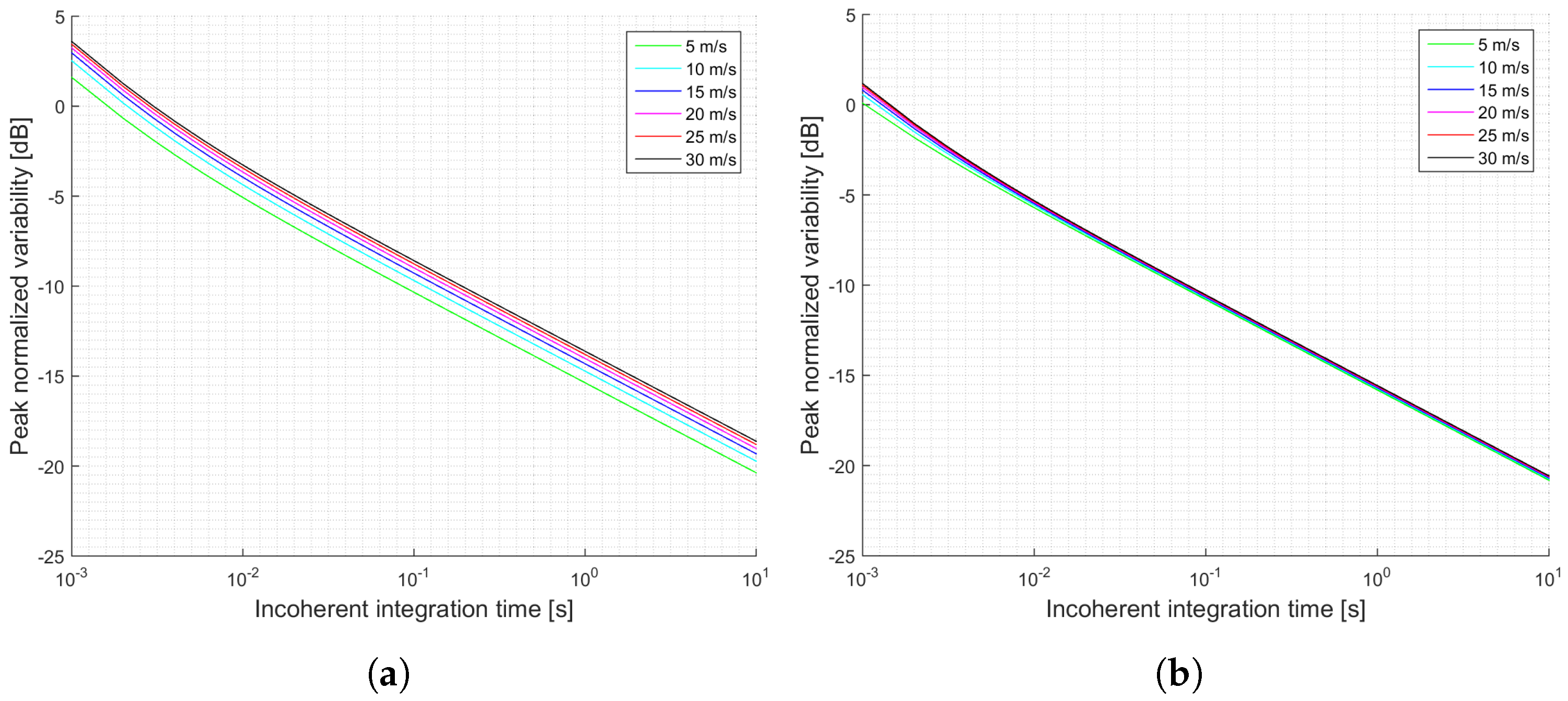
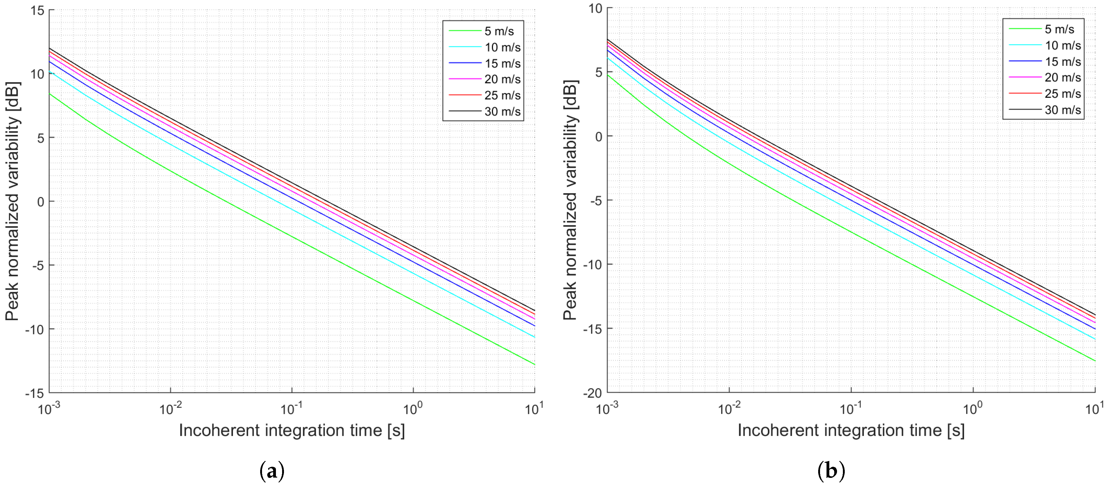
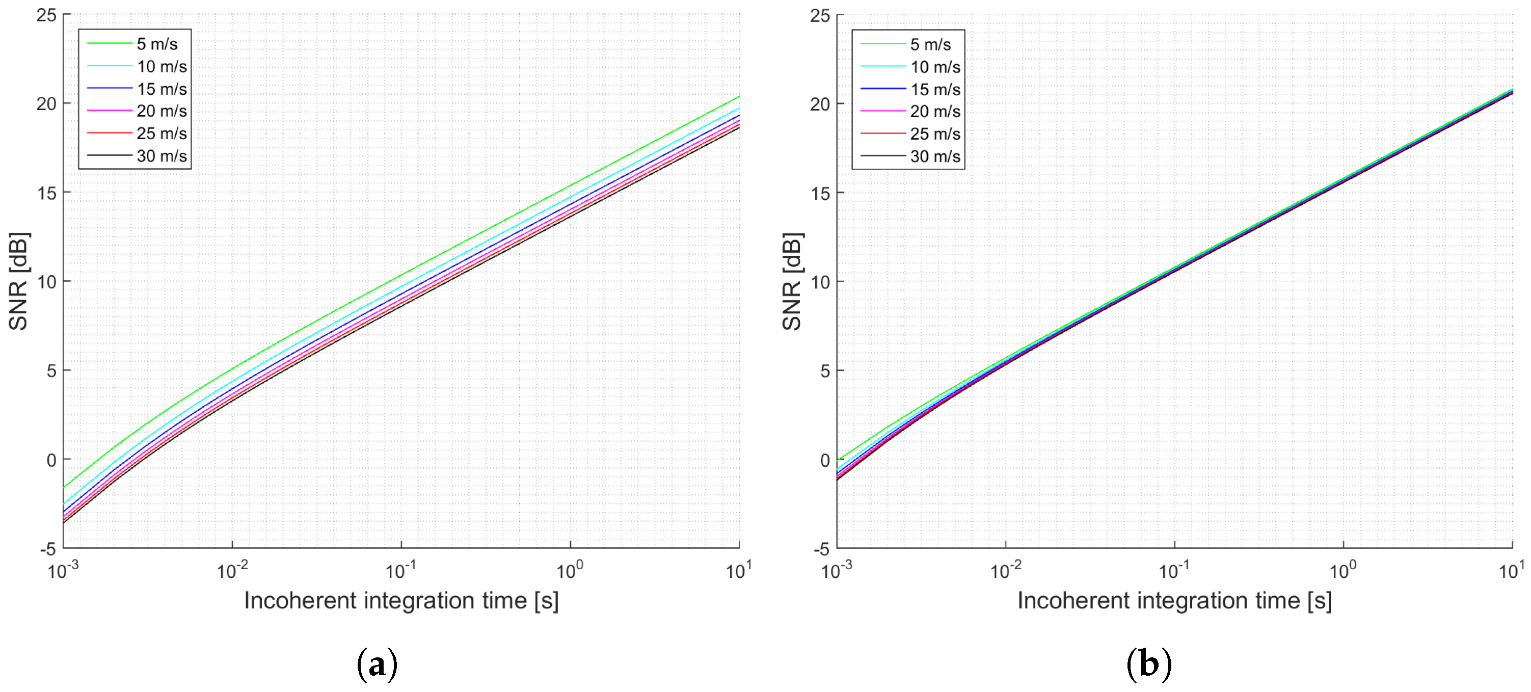
The previous section has shown several simulations for different scenarios. Firstly, it can be concluded that when the antenna directivity is relatively low, which is the case of the UK TDS-1 scenario, the signal power is an important parameter, since it increases the SNR, and decreases the signal’s variability. This effect can be observed by comparing
Figure 3a,b and
Figure 4a,b. This indicates that for those scenarios the thermal SNR is the limiting factor. The change in the slope in those scenarios is justified because first it is dominating the term that multiplies
and after several averages the term that dominates is the one that multiplies
.
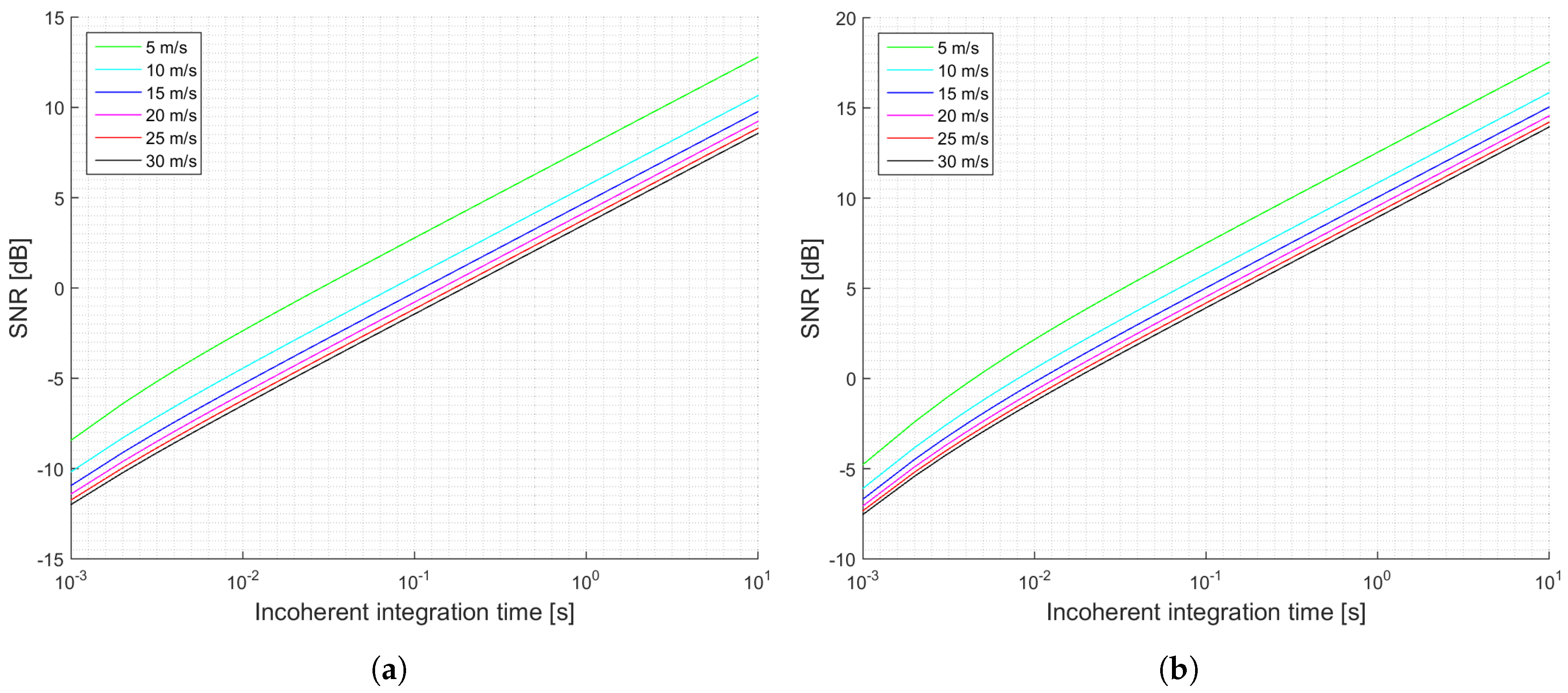
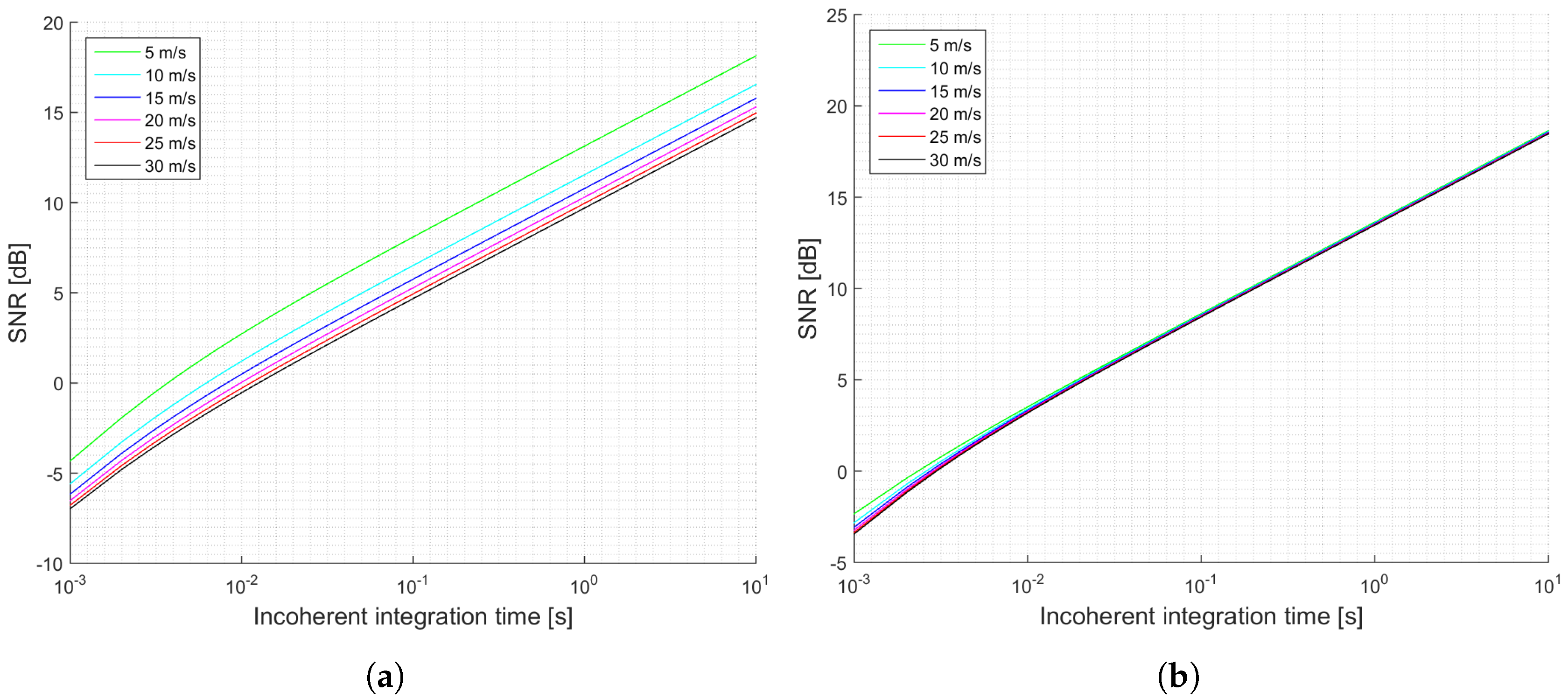
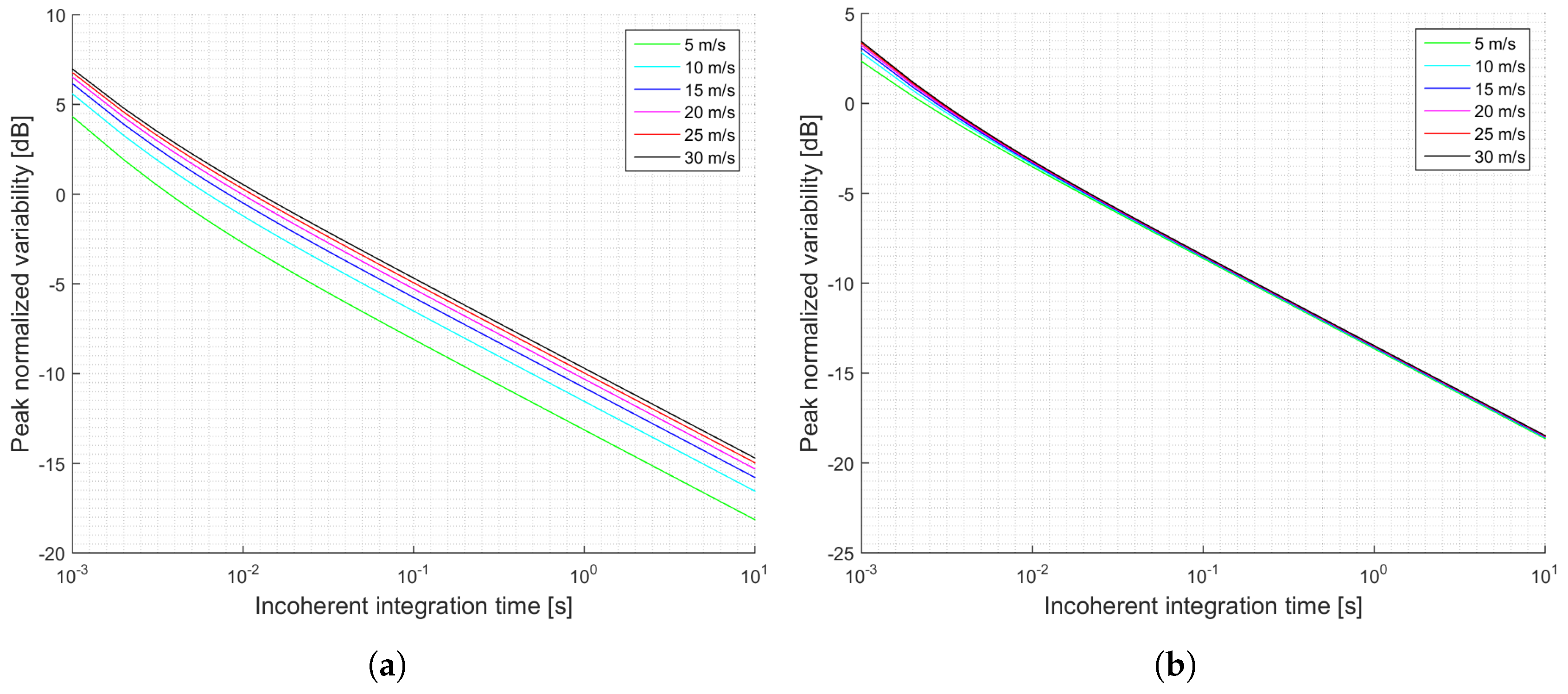
When the antenna directivity is large enough, which is in the case of the proposed antenna for the GEROS-ISS mission, the transmitted power is not that important, and the expected performance does not depend significantly on the wind speed. This can be seen by comparing
Figure 5a,b and
Figure 6a,b. Furthermore, an increase on the transmitted power by the GPS satellites results in a retrieval performance independent from the wind speed. When the antenna has a directivity of 23 dB, the incoherent power is one order of magnitude larger than the thermal noise power, and therefore it is the factor determining the SNR.
When comparing the cGNSS-R and the iGNSS-R techniques, the results of the expected SNR and the peak variability are at least 3 dB better for the cGNSS-R considering the same simulation conditions. This occurs mainly because the thermal SNR for the iGNSS-R is degraded as compared to the cGNSS-R one. Also, there is another aspect to be analyzed: the wider bandwidth codes used in the iGNSS-R translate into smaller footprints, resulting in a larger correlation time between waveforms, and a reduction of the improvement by incoherent averaging is expected as compared to the cGNSS-R approach. This is seen in the slope of the SNR graphs. For cGNSS-R approach it is a little bit larger than for the iGNSS-R. However, due to the high speed of the spaceborne platform, for the simulation conditions they were very similar.
Note that the incoherent averaging considered here includes partially overlapped waveforms, and in the case when they are not partially overlapped, the simulations presented are an overestimation of the expected performance. In that situation, would increase, resulting in a degradation of the expected SNR and an increase of the peak’s variability (the factor would become 1). However, if the antenna directivity is as large as the one in the GEROS-ISS mission, the limiting factor is the speckle noise rather than the thermal noise, and experimental results will be closer to the theoretical ones.
All equations derived in this work can be applied to any lag different from the specular one, taking into account that the coherent component in those cases will be negligible. All the necessary correlation functions are available in the Appendices, and the correlation times should be recomputed accordingly for the appropriate lag. If the surface region under analysis falls into the delay-Doppler ambiguity free zone, the Van Cittert-Zernike theorem can be used to compute the correlation times. However, if delay-Doppler ambiguity exists, it should be computed taking into account two different areas contributing to the same delay-Doppler cell.
9. Conclusions
This work has analyzed the expected SNR and estimated variability for cGNSS-R and iGNSS-R from a theoretical point of view including the presence of a coherent scattering component, which had been neglected in previous works. Recent UK TDS-1 data shows that for some types of surfaces the coherent component cannot be disregarded, and therefore the reflected signal does not always obey Gaussian statistics, but a Hoyt one.
Theoretical expressions of the expected SNR and the estimated variability are presented in this work which allow to predict the scatterometric performance of any GNSS-R mission. The first important point is that, if the antenna directivity is not large enough, thermal SNR is the main limiting factor of the scatterometric performance. However, if it is sufficiently large, speckle noise becomes the limiting factor, and in that case, the cGNSS-R always performs better than the iGNSS-R because the equivalent thermal noise is lower. The second important point is that, the larger the transmitted power or the larger the directivity, the lower the dependence on the wind speed. The directivity threshold when the speckle noise is the entirely dominant term lies on 23 dB.
The averaging of partially overlapped waveforms has also been proposed and analyzed in this work, as it would help to reduce the signal variability induced by thermal noise up to 0.88 dB. However, this technique is mainly applicable to spaceborne scenarios where the platform moves faster enough, and the surface correlation time is around 1–2 ms, while under airborne situations the surface correlation time may be sometimes larger and speckle noise would become the limiting factor.

 ,
, 


