
A Precise Visual Method for Narrow Butt Detection in Specular Reflection Workpiece Welding


Abstract
:1. Introduction
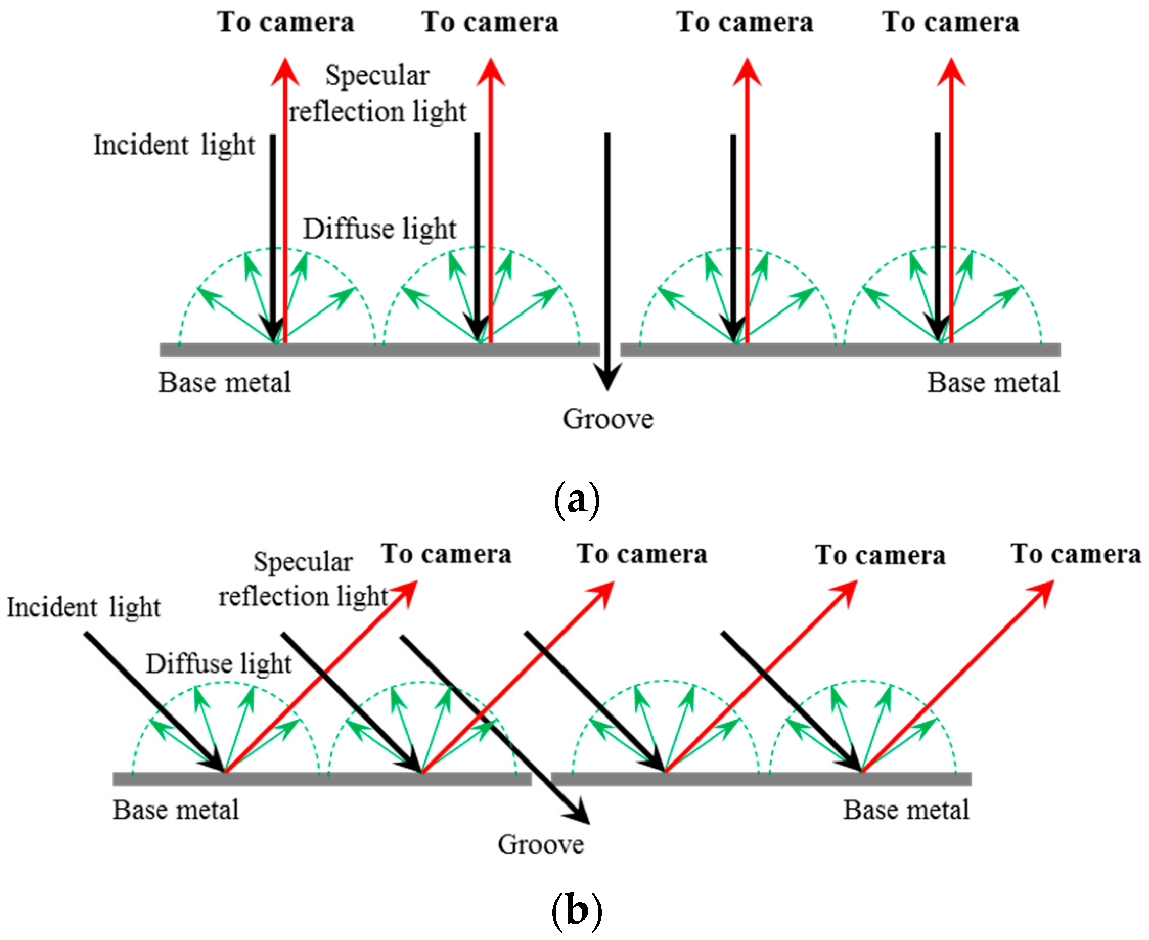
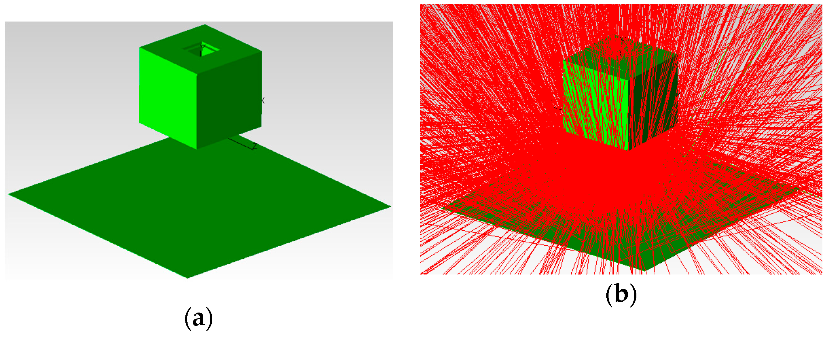
- Specular reflection surface of the workpiece. The components are usually made of aluminum alloy, titanium alloy and stainless steel, which may strongly reflect the incident light. For example, the reflectance of aluminum to visible light can be over 95% [8]. The strong specular reflection effect will lead to the non-uniform grayscale distribution in the images, lowering the signal-to-noise ratio (SNR) of imaging.
- Small width of the narrow butt joint. The workpieces to be welded are mounted close to each other, which is called the “narrow butt”. The width of the butt joint is significantly small (smaller than 0.2 mm), which requires a precise detection method.
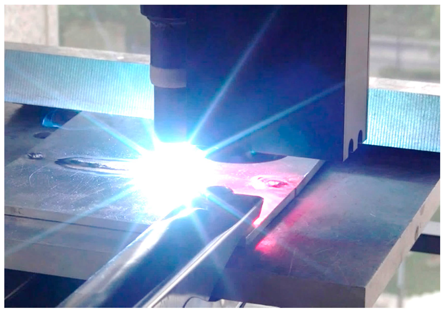
- Small welding region. The components are usually joined by gas tungsten arc welding (GTAW), friction stir welding or high energy beam welding (such as laser, electron beam and plasma arc welding) methods. The welding region is usually small, so that the welding quality would greatly deteriorate even though there is a small deviation between the torch and the welding path.
- High welding speed. The welding speed can reach 3 m/min or higher in high energy beam welding, which requires a real-time detection method. It is essential to get high SNR images and develop efficient image processing algorithm in order to meet the real-time detection needs.
2. Visual Detection Method of Narrow Butt of Specular Reflection Workpiece
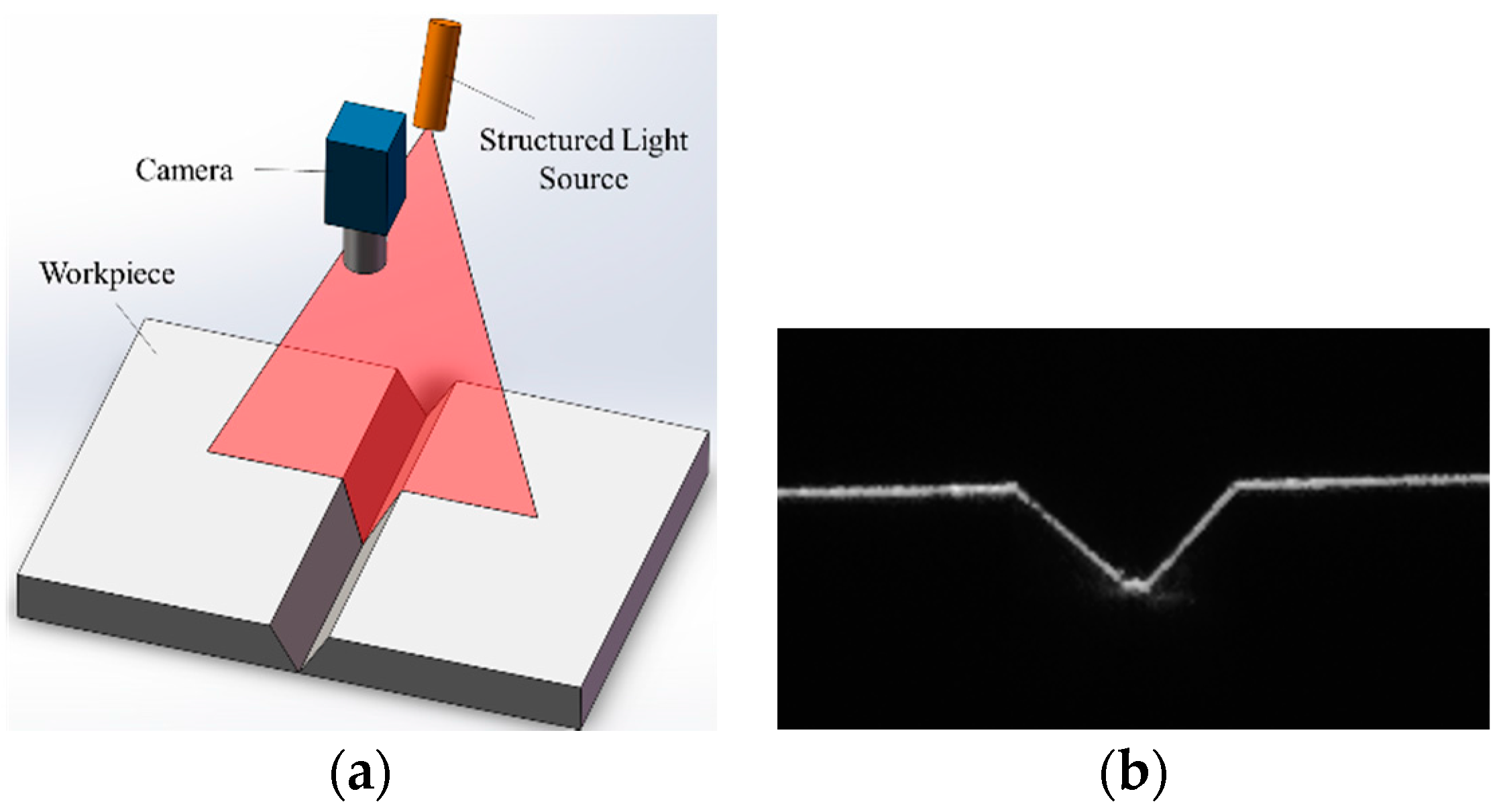
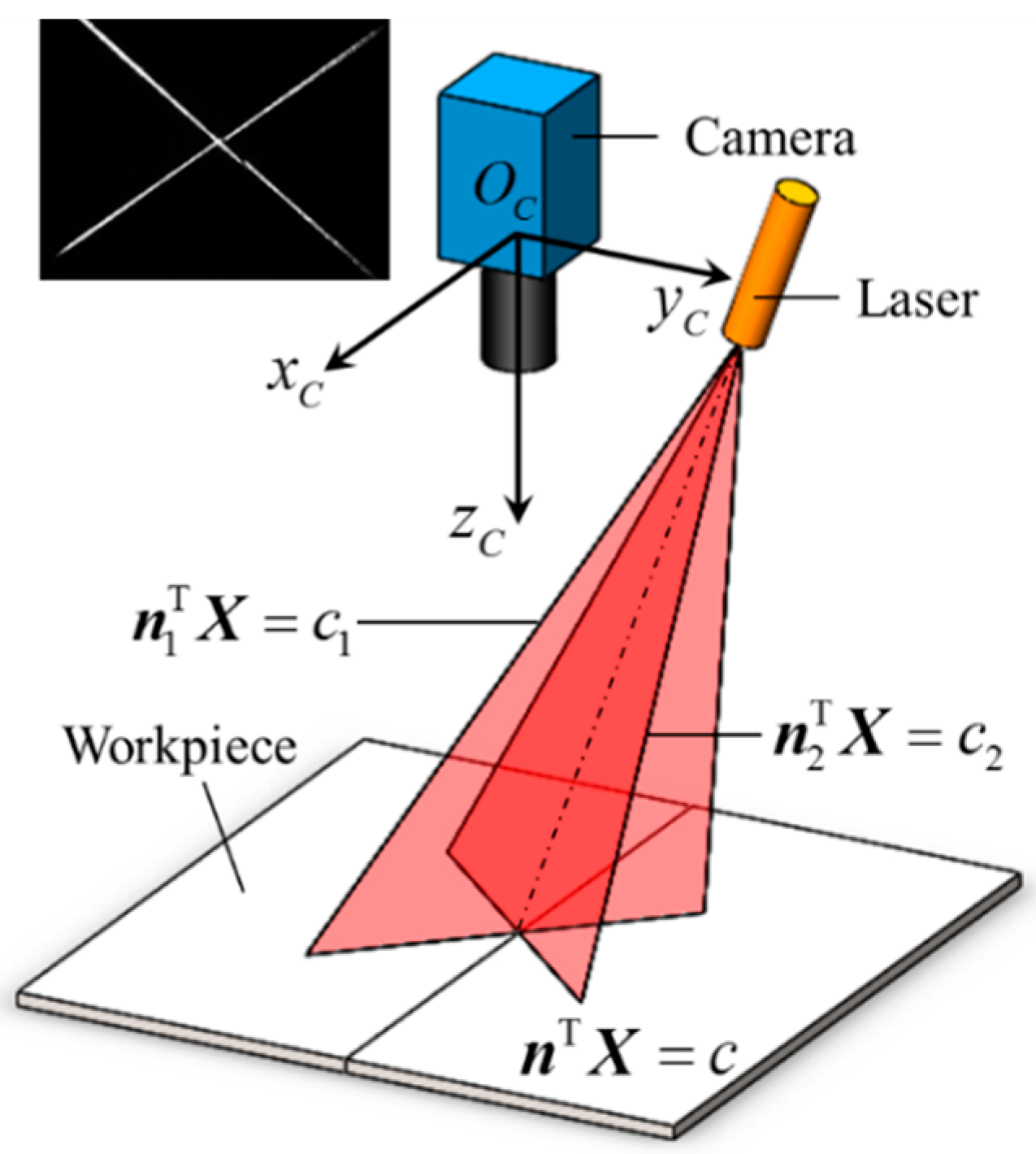
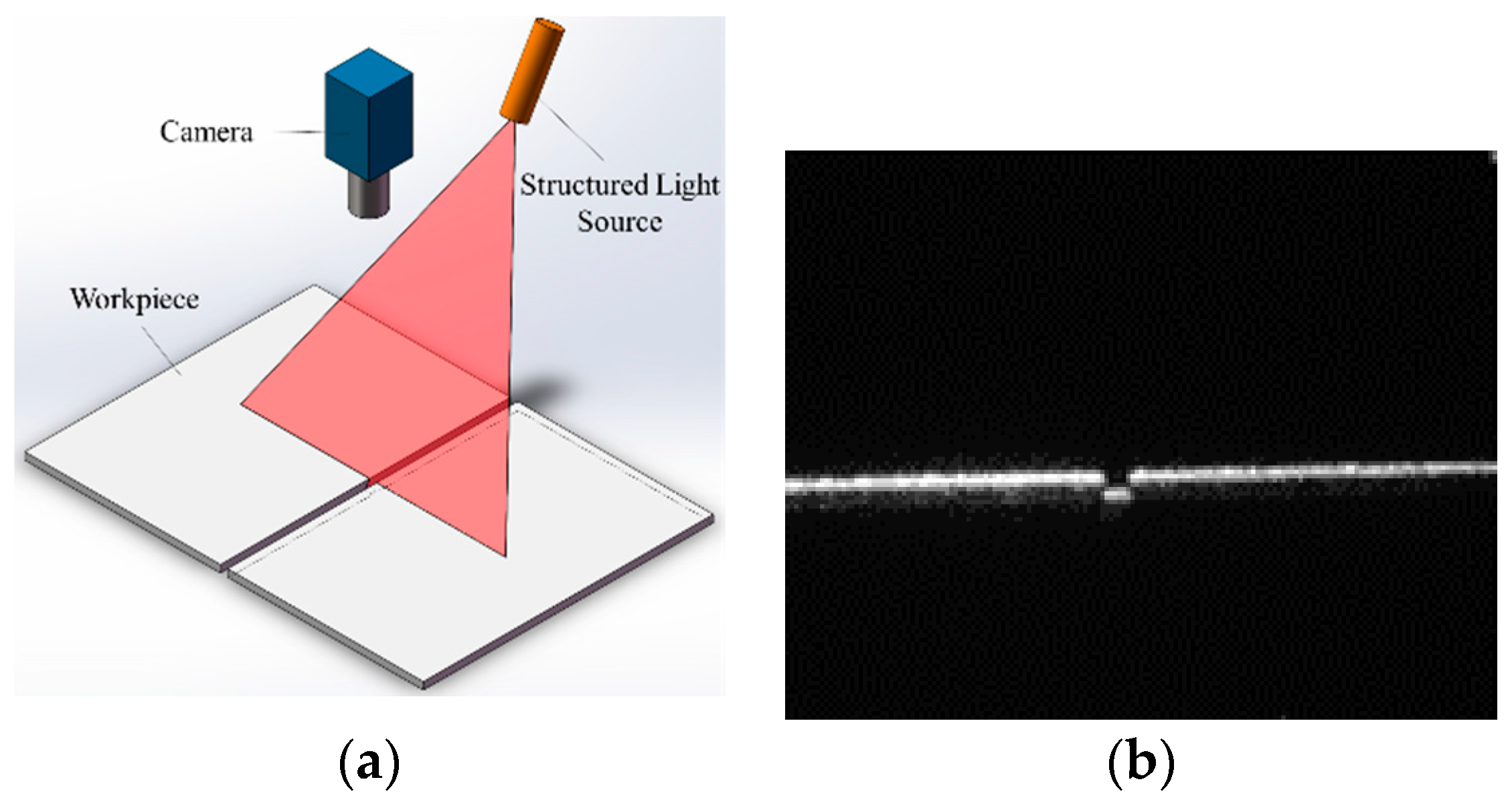
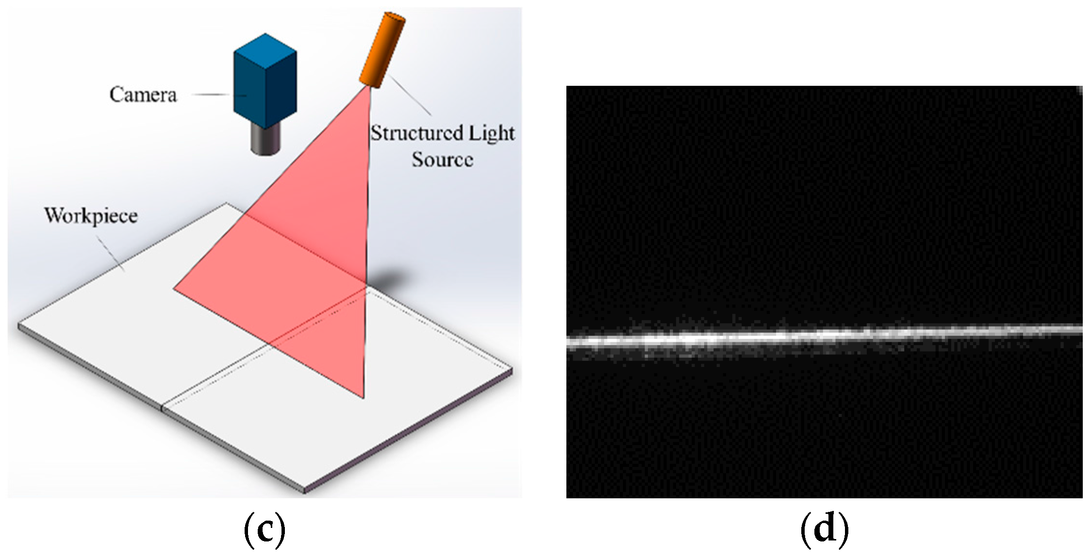
2.1. Principles of the Narrow Butt Visual Sensing Method of Specular Reflection Workpieces
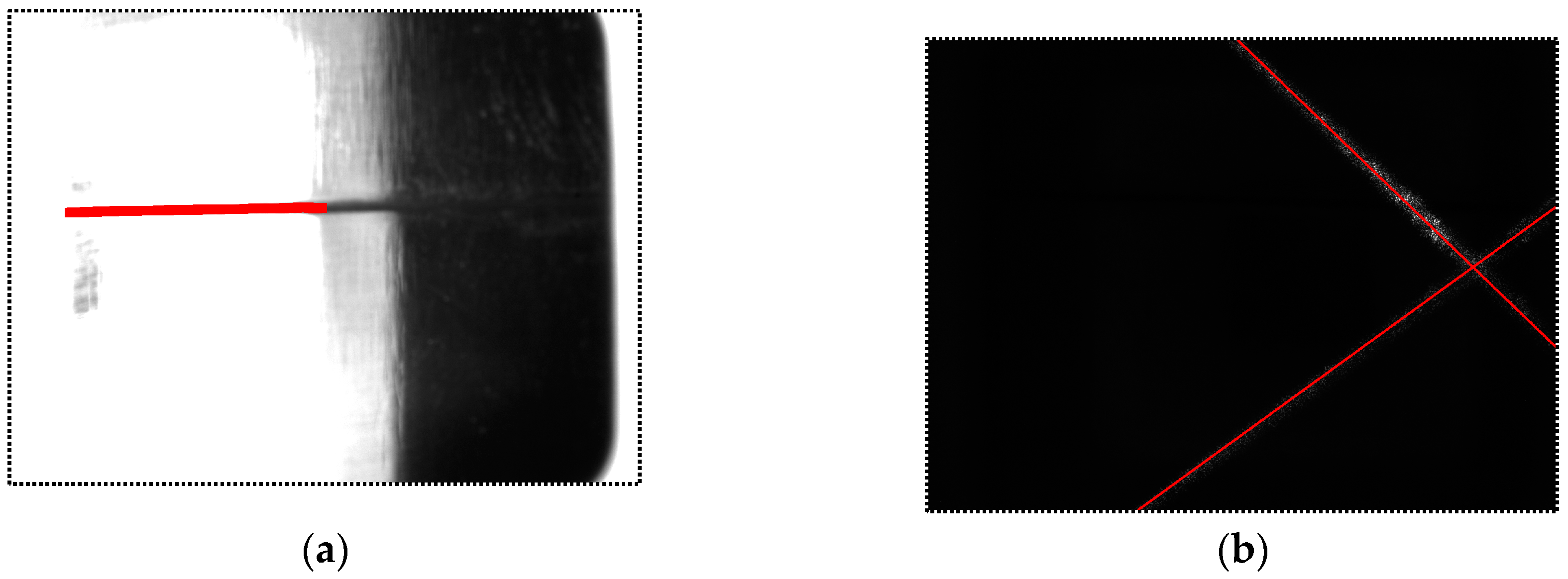
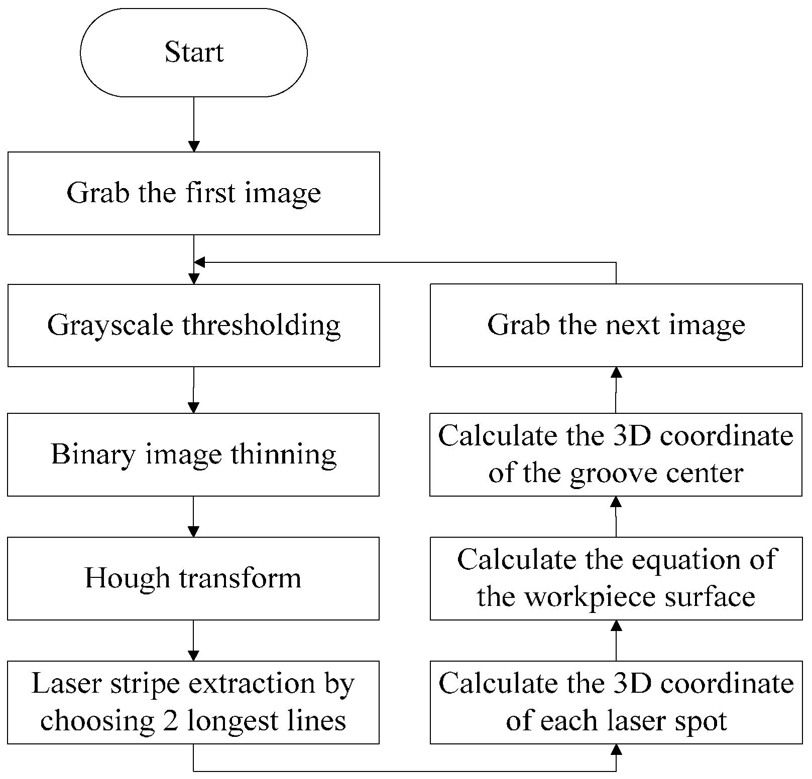
2.2. Image Processing Algorithm of Narrow Butt Detection
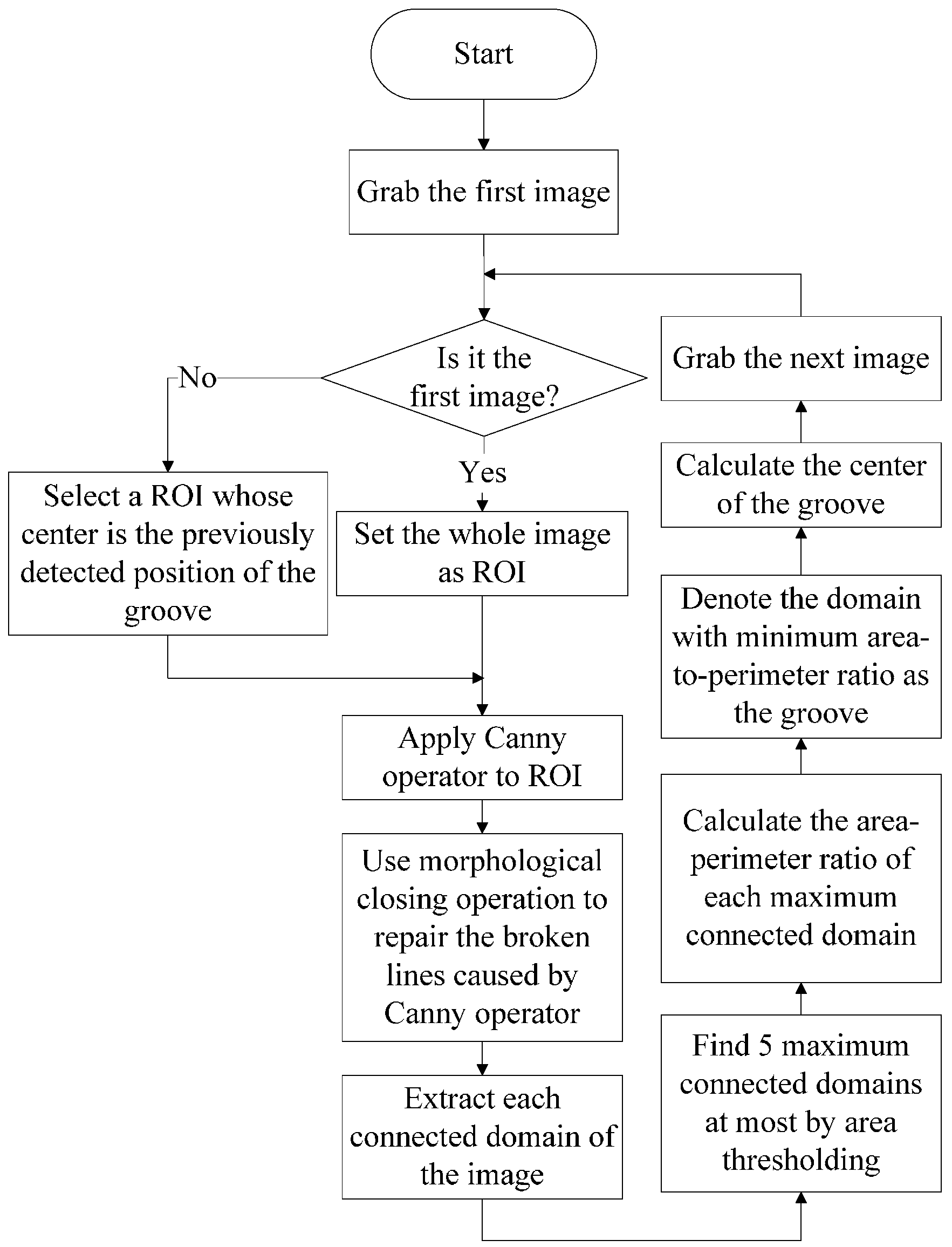
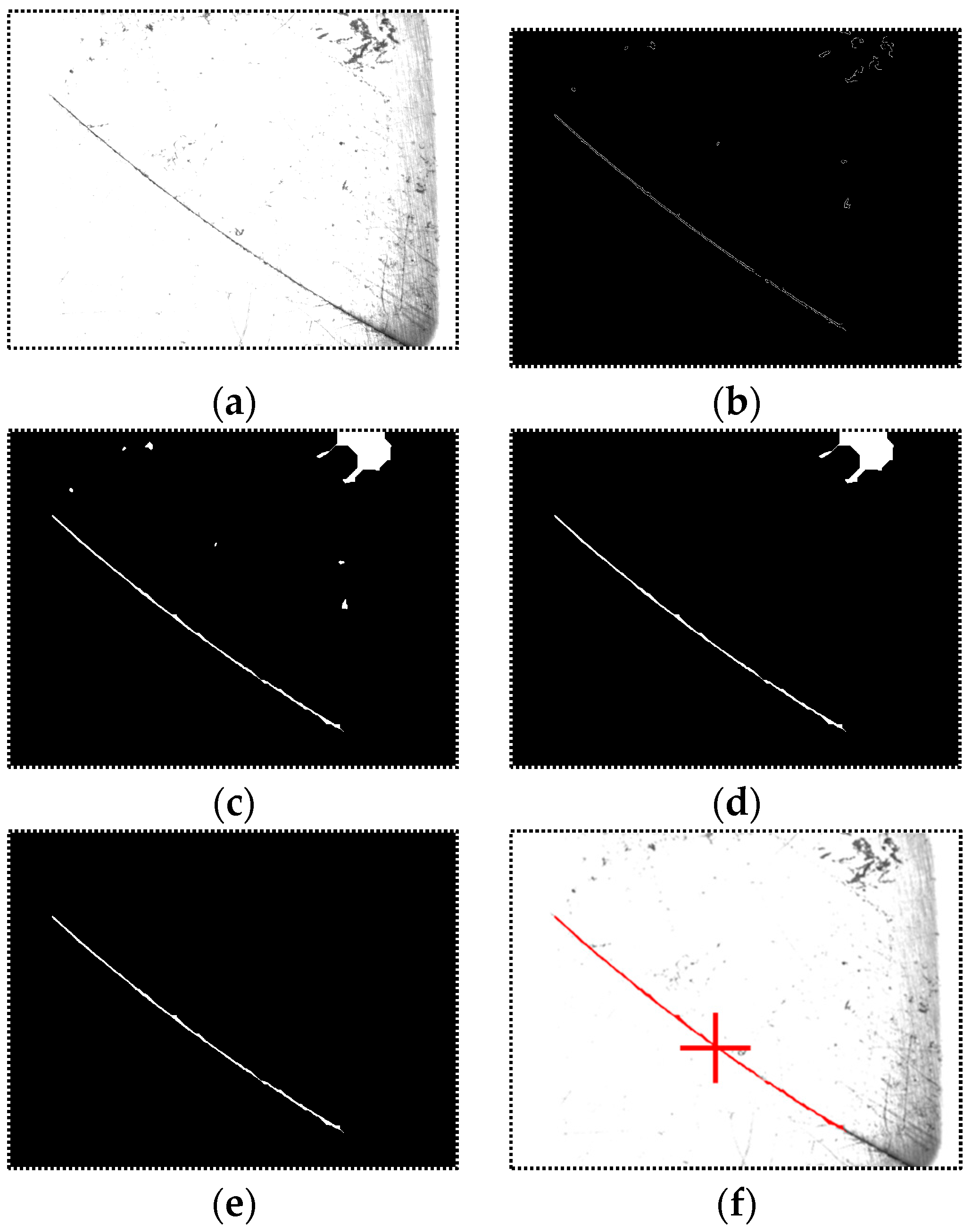
- Region of Interest (ROI) setting. If the image I1(x,y) is the first one, set the whole image as ROI. Otherwise, the center of the ROI is located in the previously detected position of the groove; the width and the height of the selected ROI are all half of those of the whole image. Denote the ROI as R1(x,y).
- Canny operation. Apply the Canny operator to R1(x,y) and a binary image B1(x,y) can be obtained containing the two-sided edges of the groove.
- Morphological closing operation. The continuous groove region would become broken after the edge extraction process by the Canny operator. The morphological closing operation is used to repair the broken edges and fill the blank region between two edges of the groove as well. The image after morphological closing operation is denoted as C1(x,y).
- Connected domain extraction and thresholding based on domain area. The flood-fill algorithm is used to extract each connected domain of the image C1(x,y). Then thresholding is used to eliminate the isolated connected domains with small areas. In this paper, at most five connected domains with maximum areas are left.
- Find the domain with minimum area-to-perimeter ratio (APR) as the groove. In the groove region, the APR is about half of the groove width, which is usually small. In other regions with large areas, we can assume that these regions can be regarded as circles approximately. Therefore, the APRs of these regions are about a quarter of the width of themselves, which are usually much larger than half of the groove width. Calculate the APR of each connected domain and the minimum one indicates the groove region most probably.
- Calculate the groove center. Scan each row or column of the groove region and we can finally obtain the trace of the groove center.
3. Position and Pose Detection between the Welding Torch and the Workpiece Surface
4. Establishment of the Narrow Butt Detection Sensor
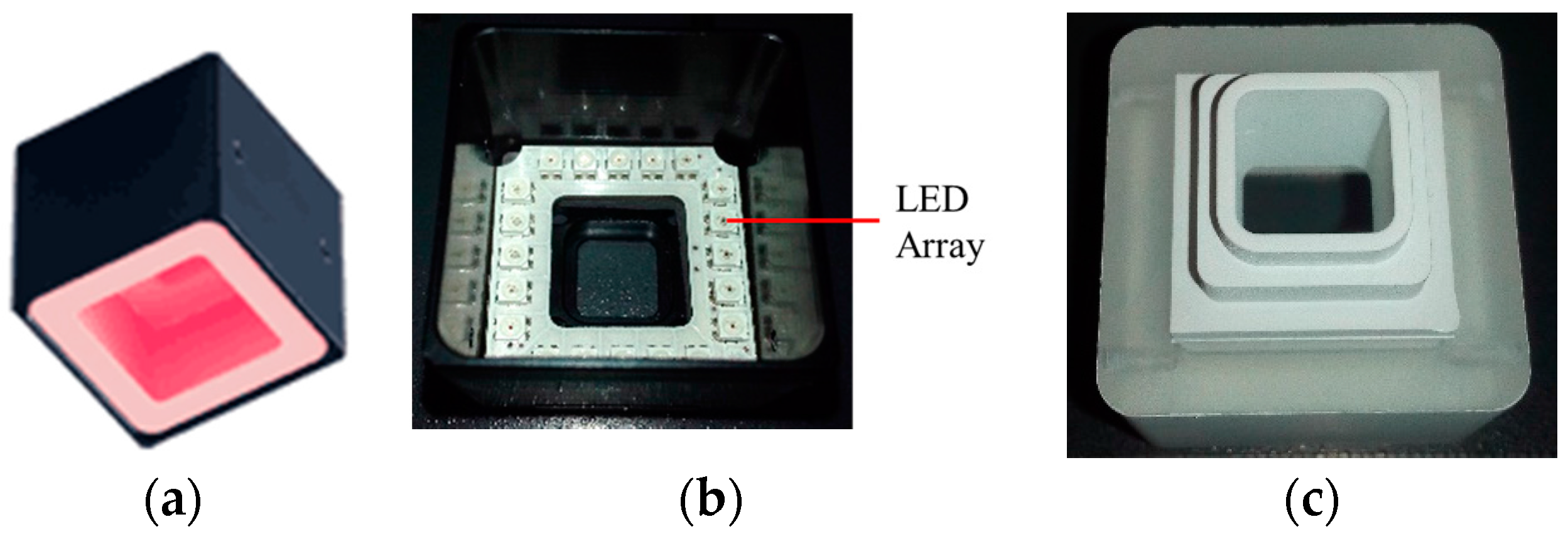
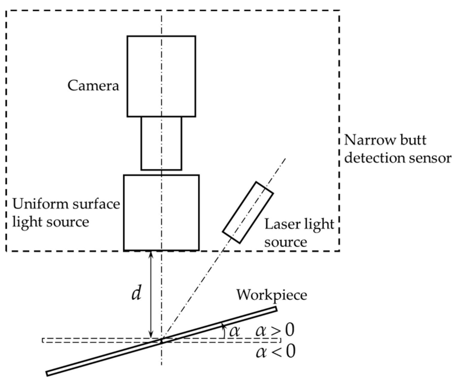
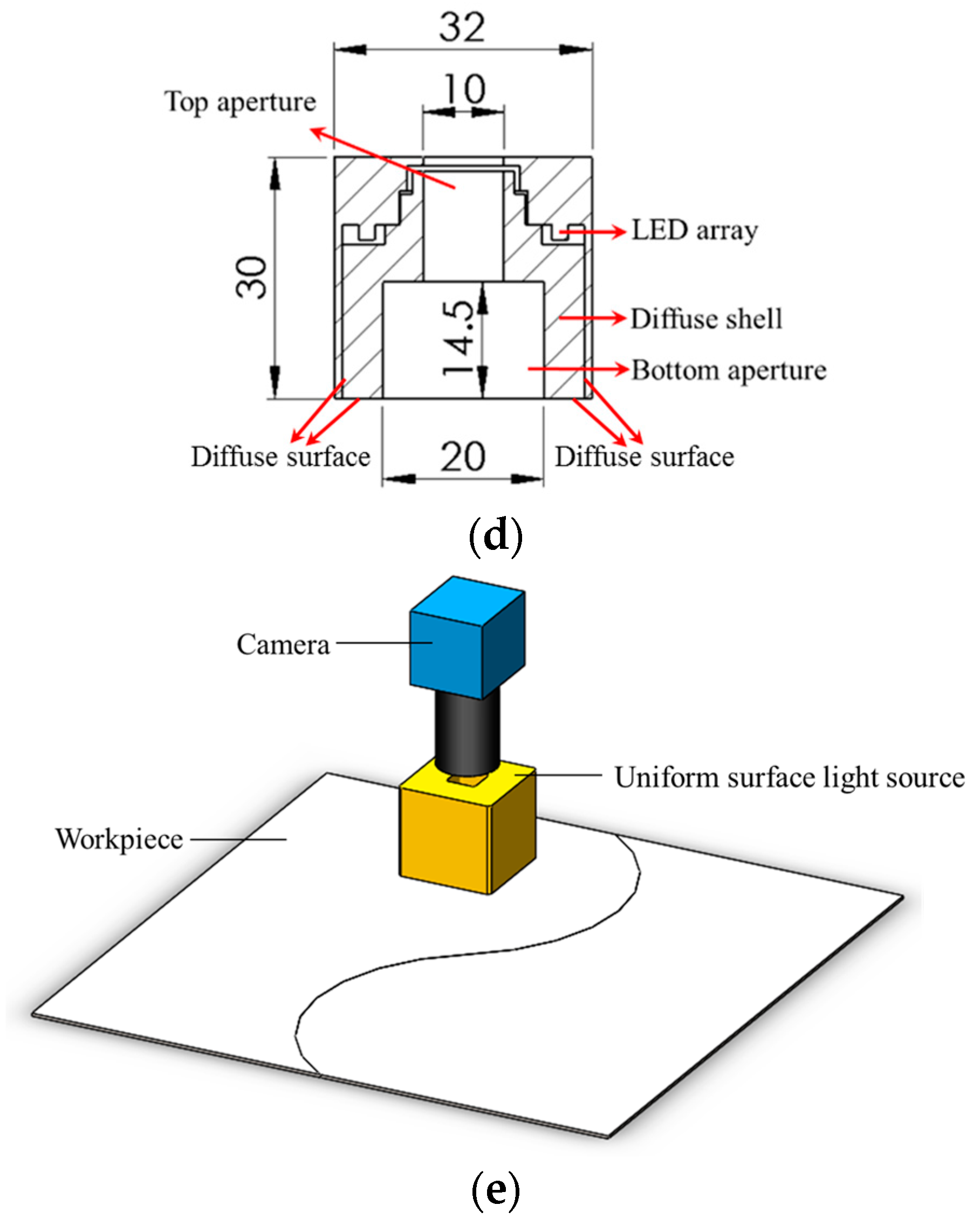
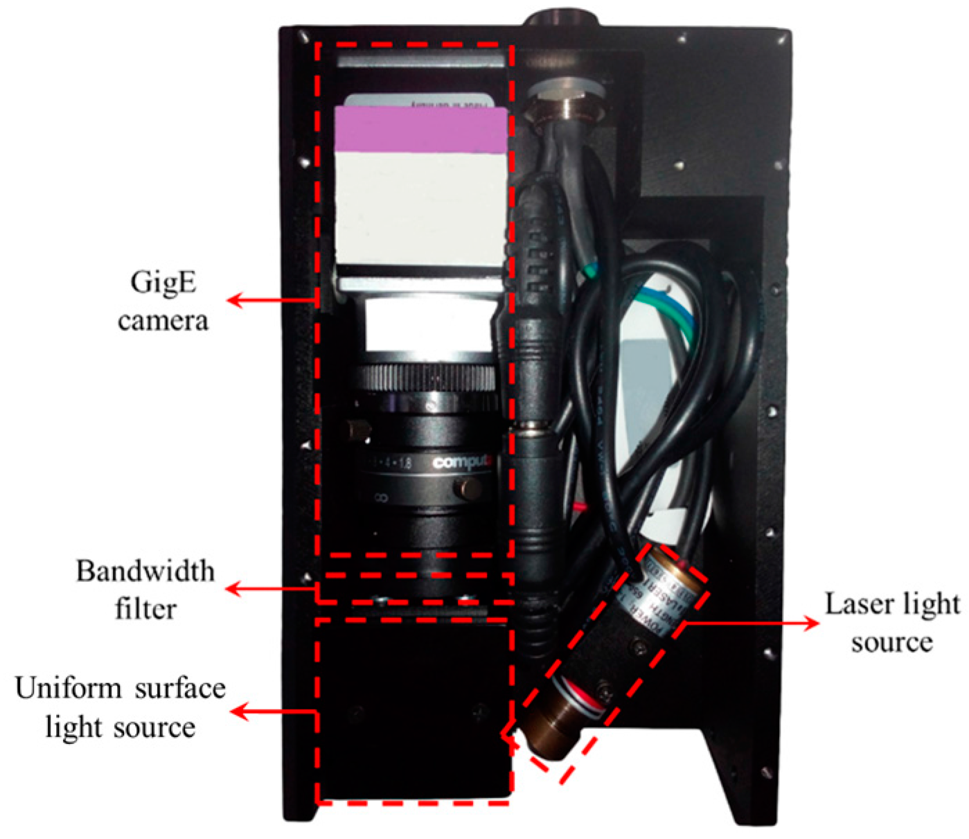
4.1. Configuration of the Narrow Butt Detection Sensor
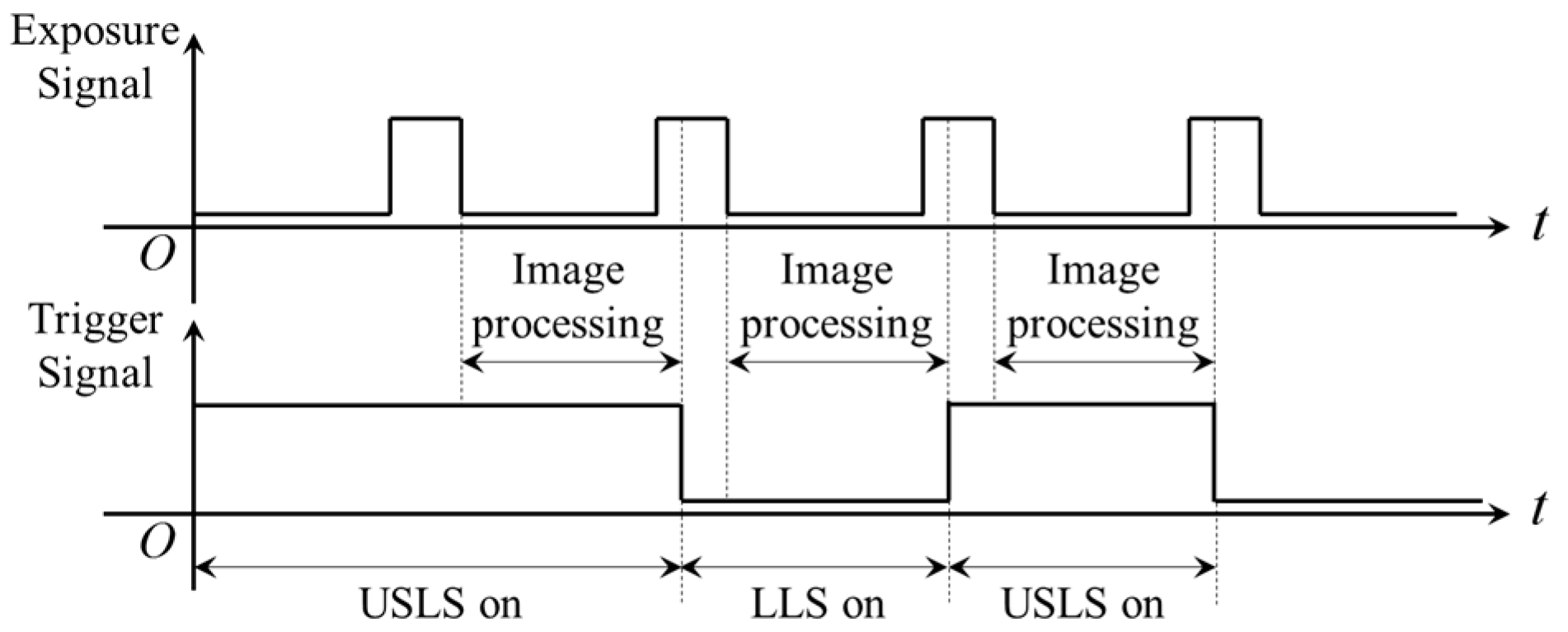
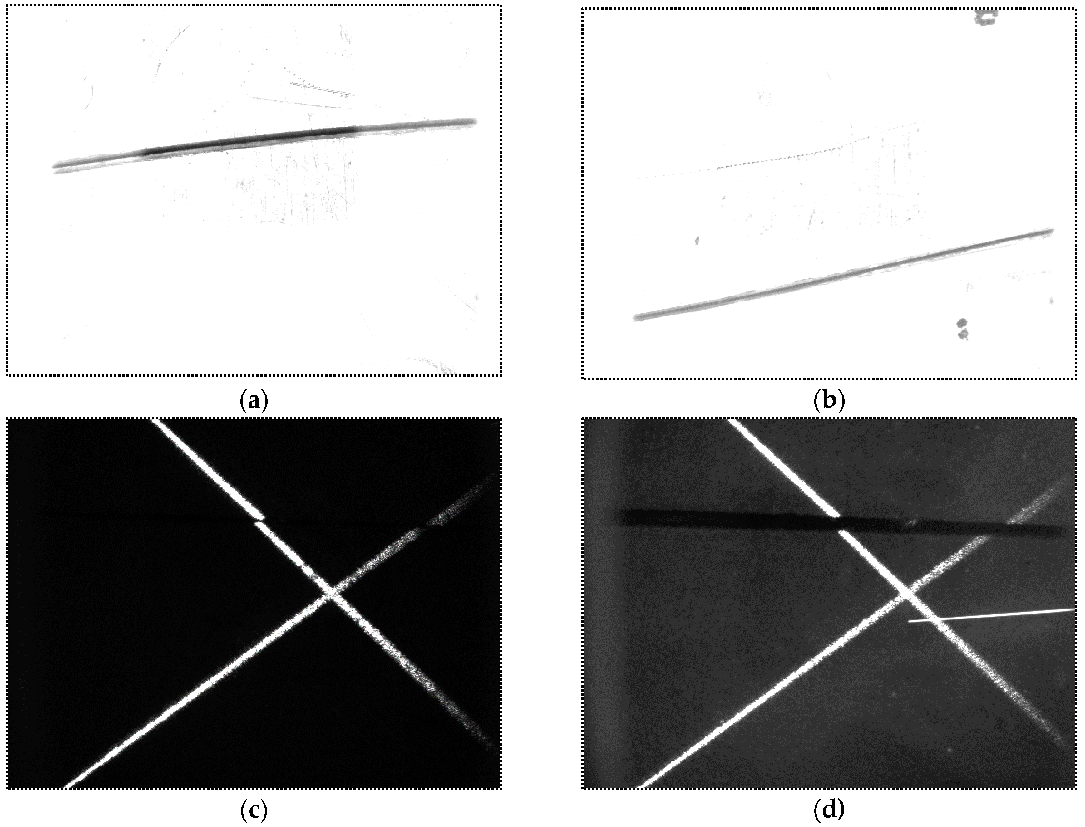
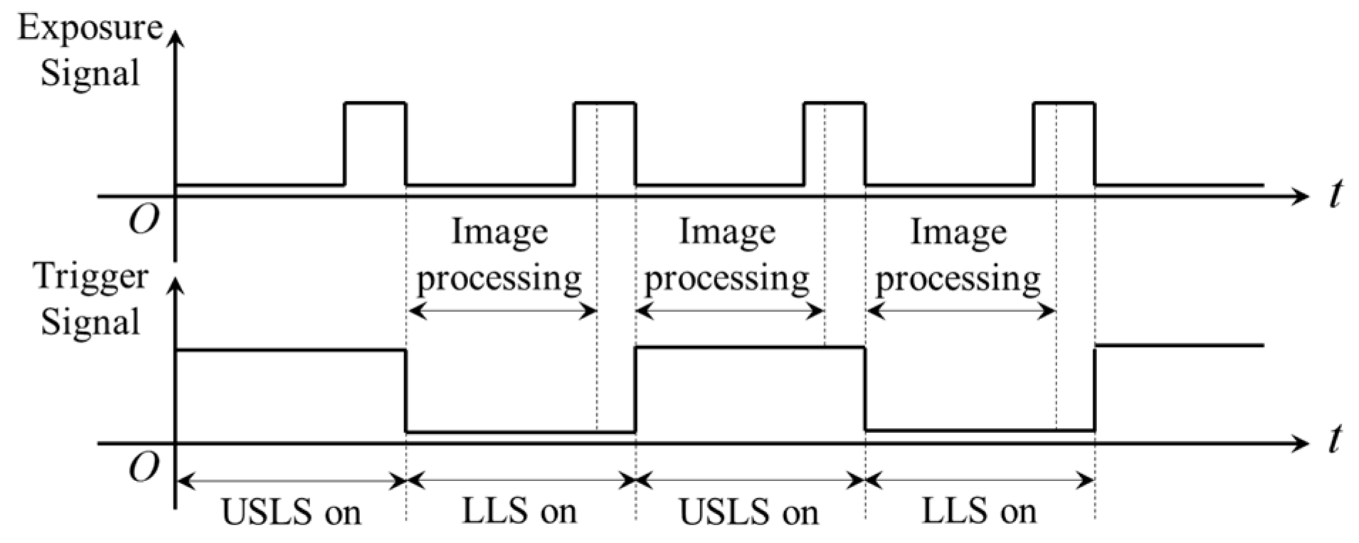
4.2. The “Shutter-Synchronized Dual Light Stroboscopic” Method
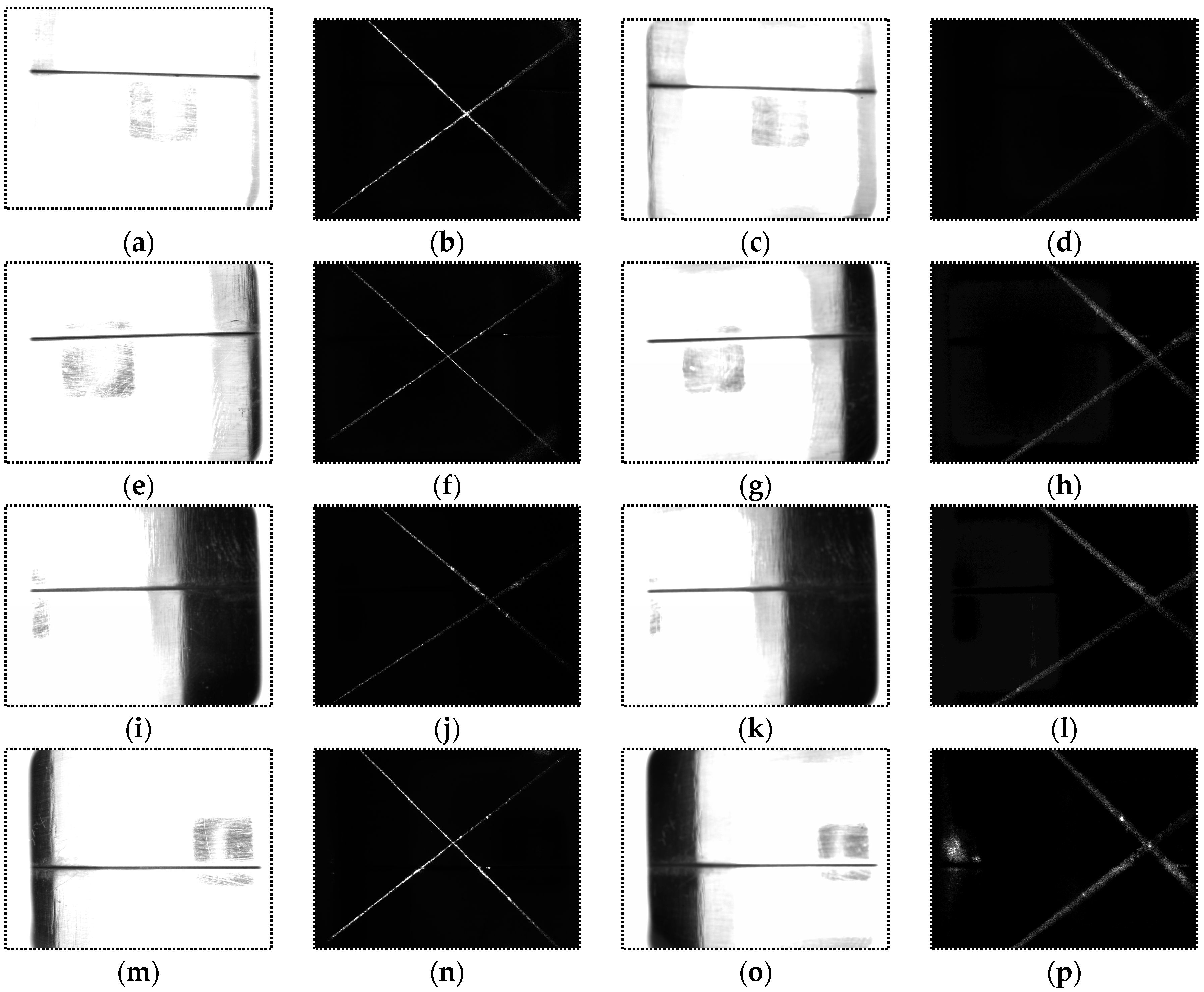
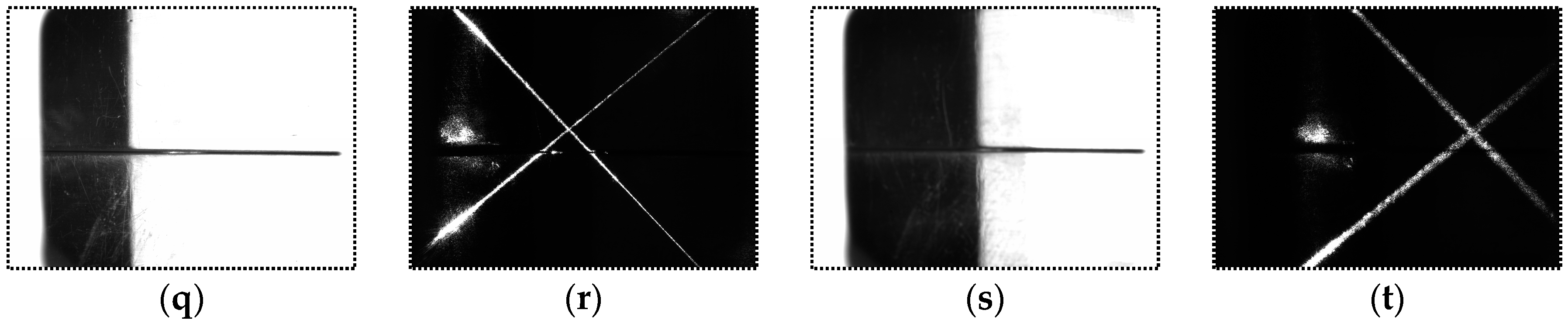
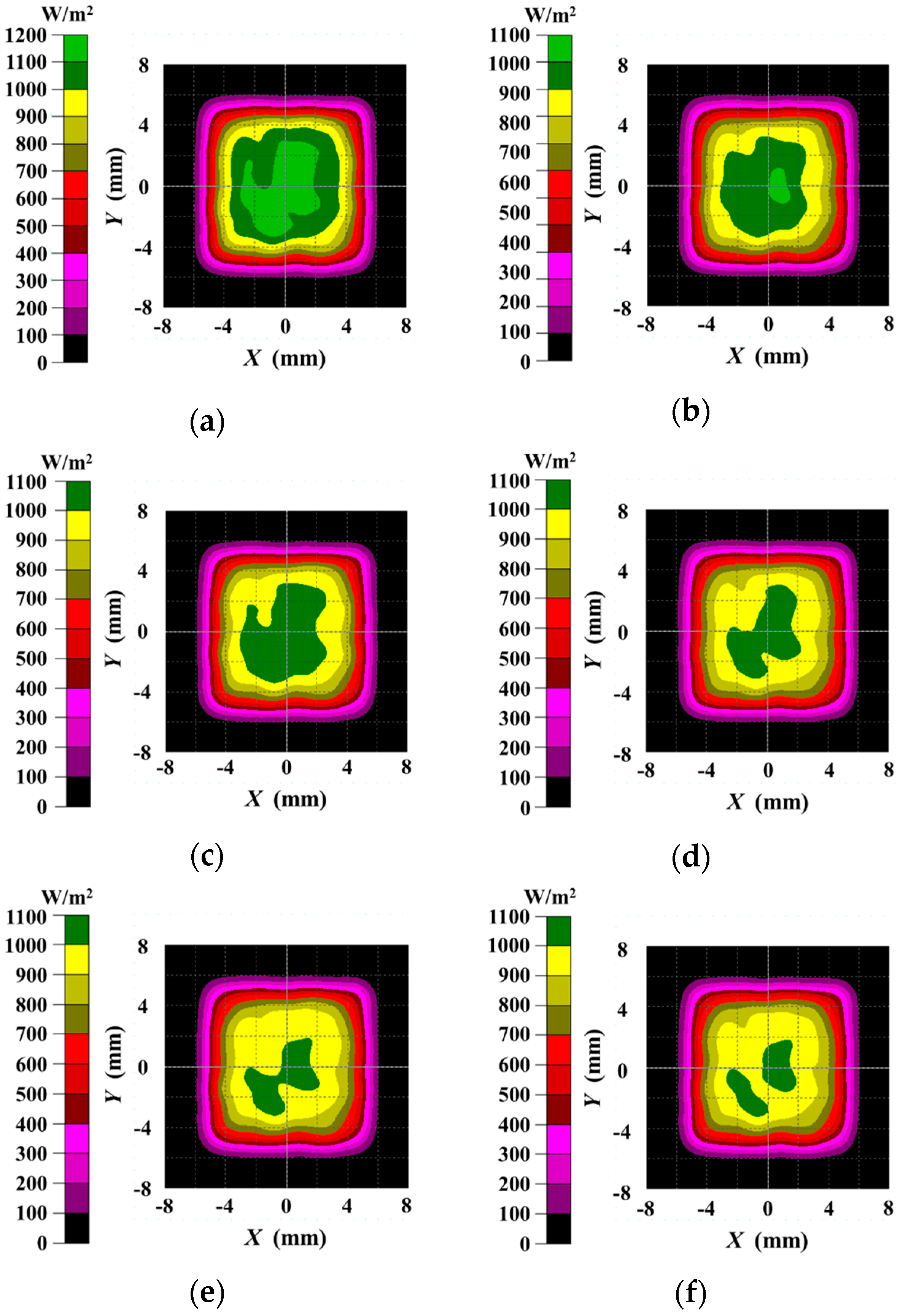
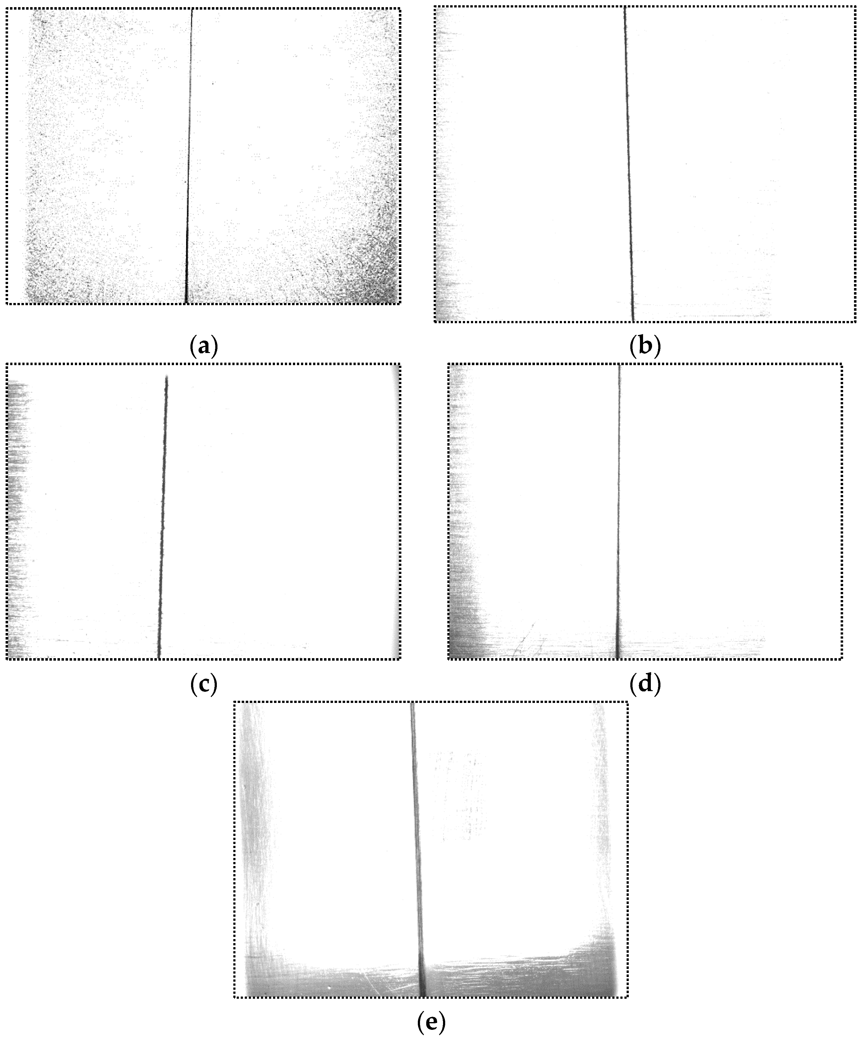
4.3. Images Captured in Different Distances and Angles
5. Experiments of Narrow Butt Detection and Discussions
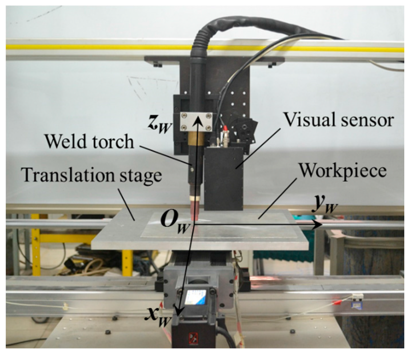
5.1. Configuration of the Experiment Platform
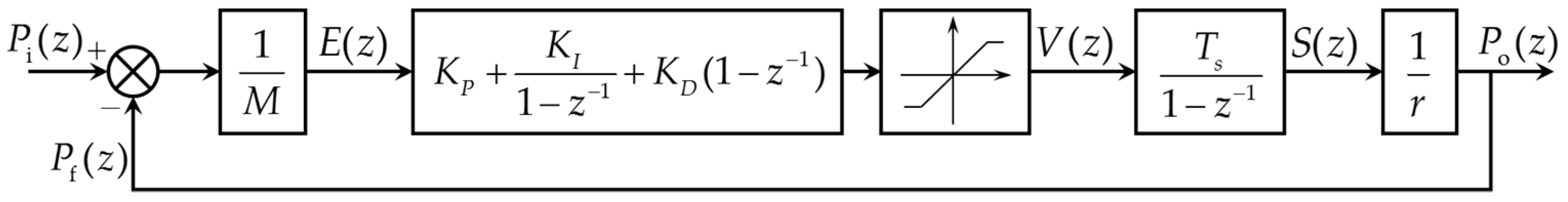
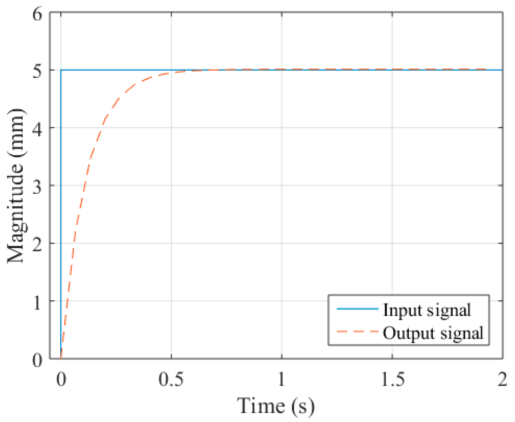
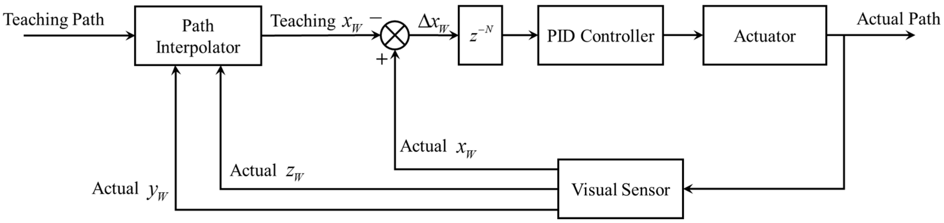
5.2. Motion Control System Design During Path Teaching
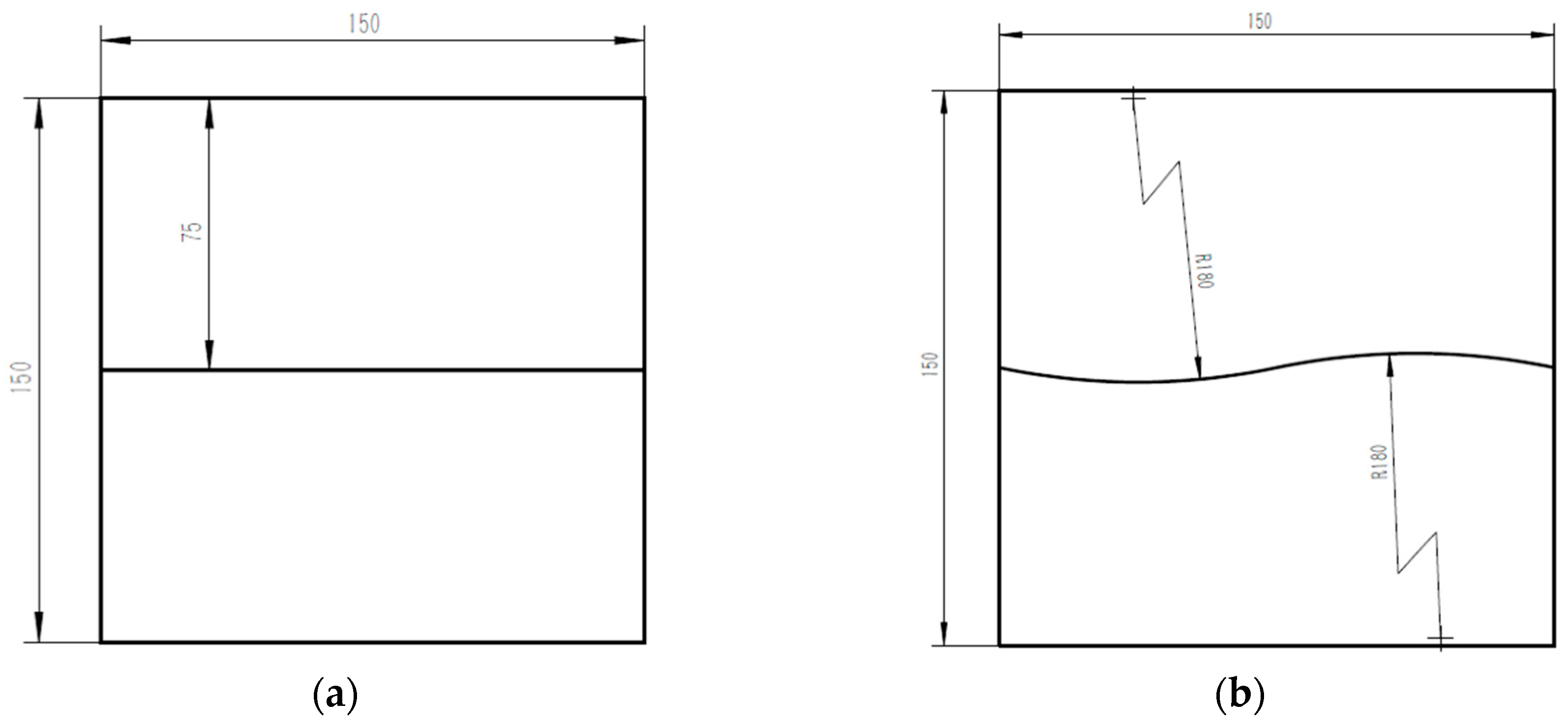
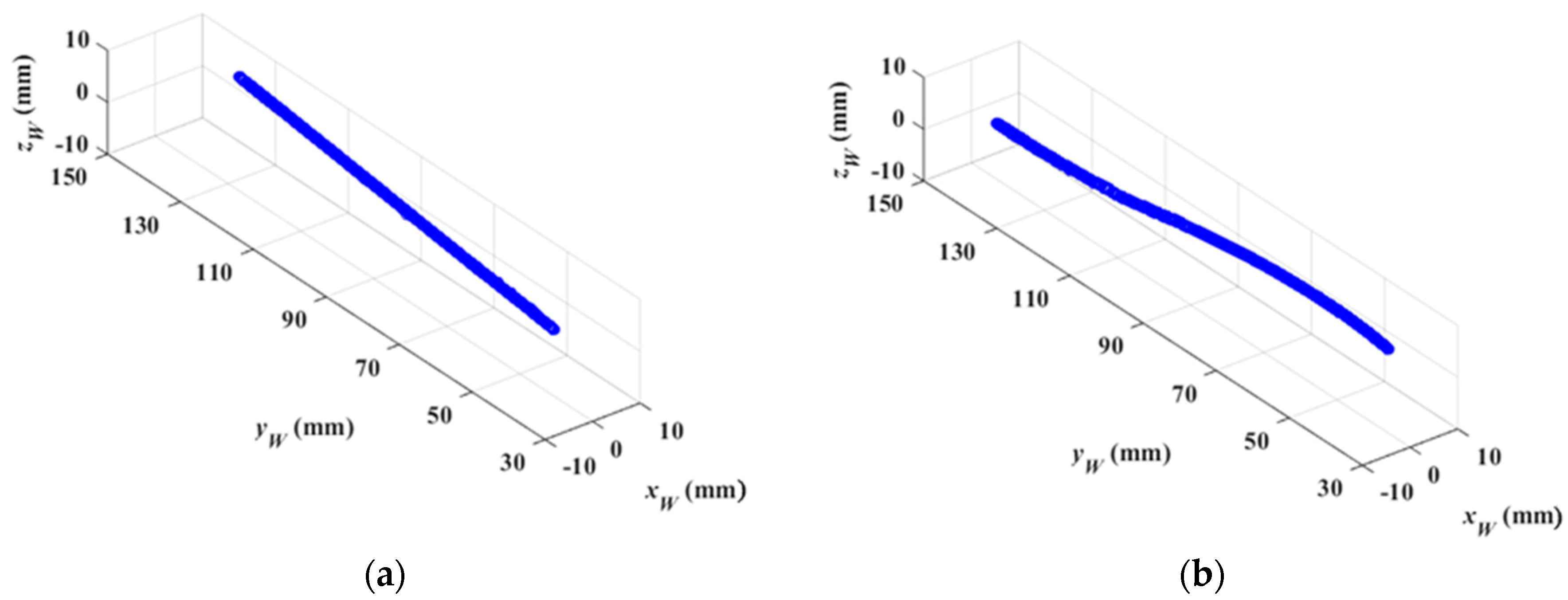
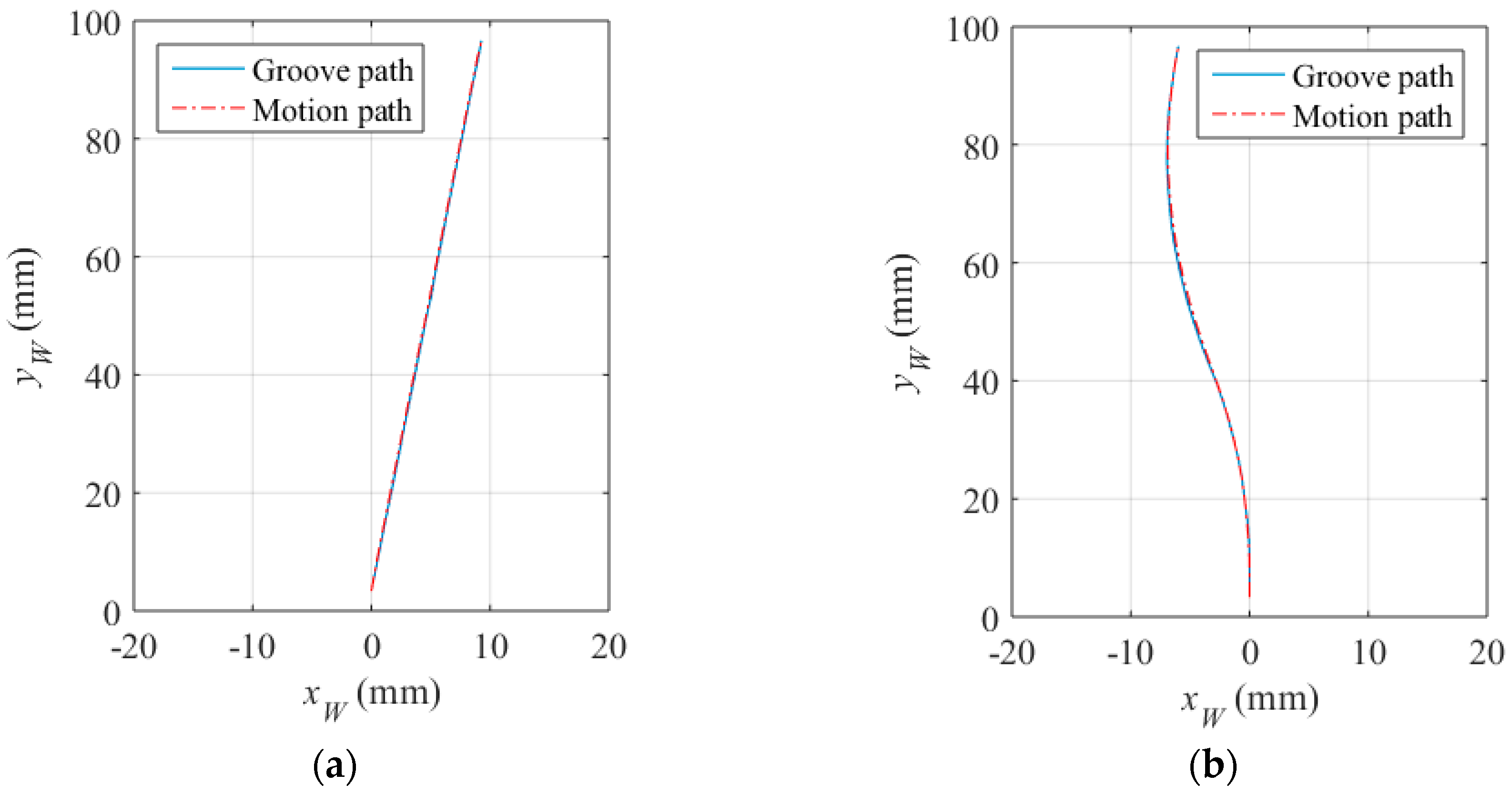
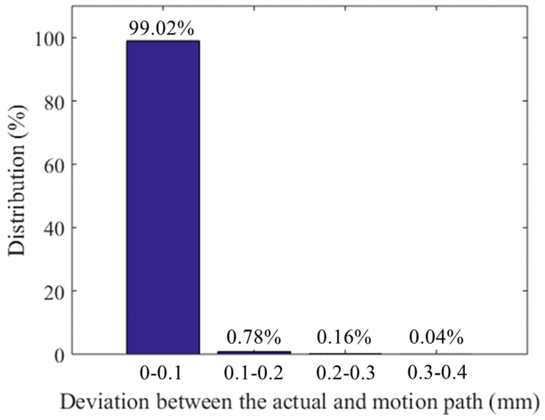
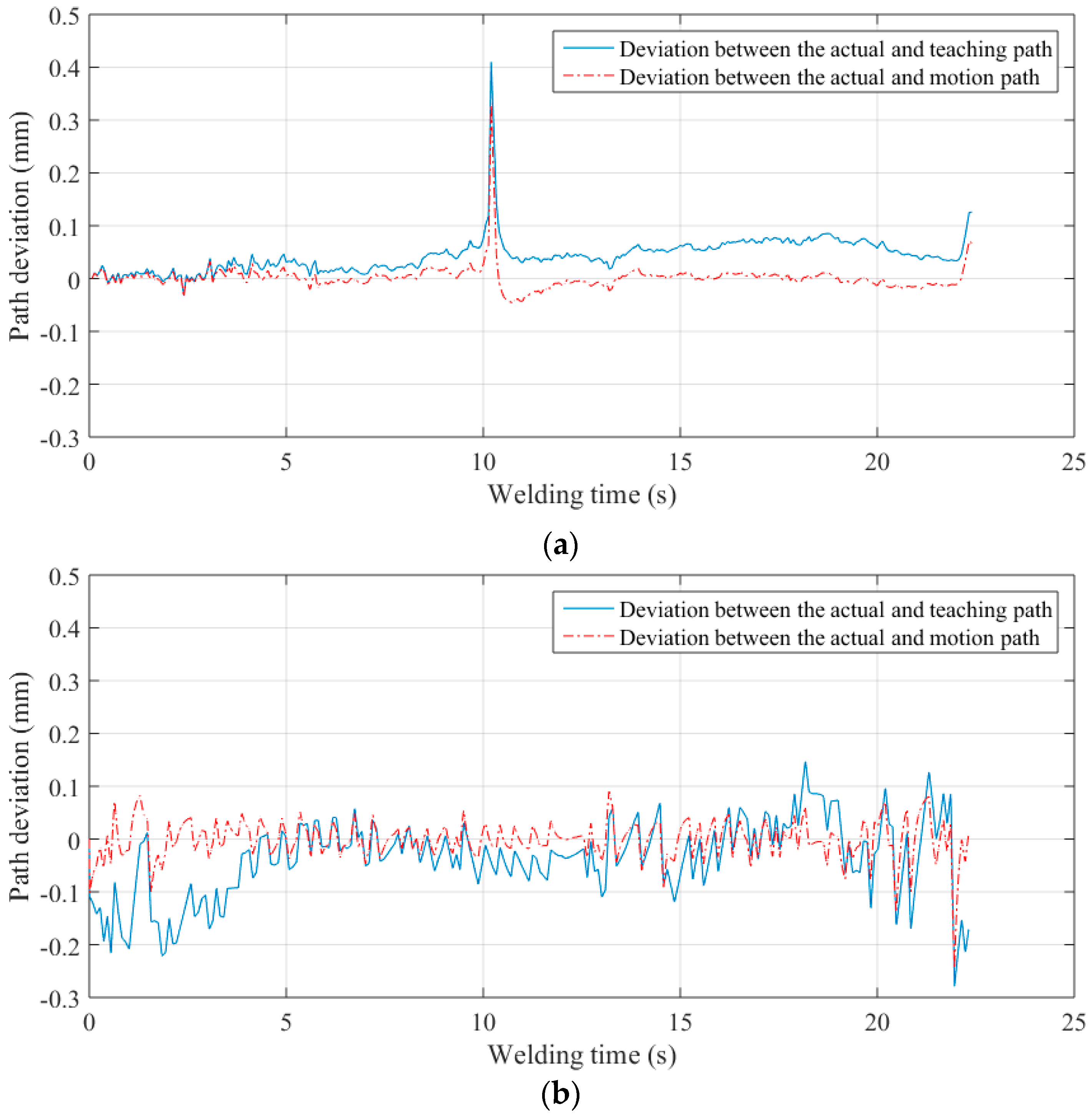
5.3. Path Teaching Results and Discussions
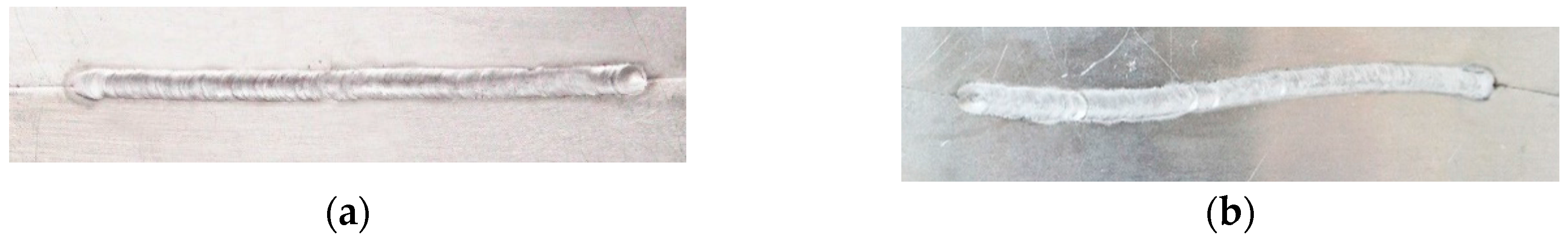
5.4. Real-time Tracking Experiments during Welding and Discussions
6. Conclusions
Acknowledgments
Author Contributions
Conflicts of Interest
References
- Tsai, M.J.; Lee, H.W.; Ann, N.J. Machine vision based path planning for a robotic golf club head welding system. Robot. Comput.-Integr. Manuf. 2011, 27, 843–849. [Google Scholar] [CrossRef]
- Tsukamoto, S. High speed imaging technique part 2-high speed imaging of power bean welding phenomena. Sci. Technol. Weld. Join. 2011, 16, 44–55. [Google Scholar] [CrossRef]
- Zeng, J.; Zou, Y.; Du, D. Research on a visual weld detection method based on invariant moment features. Ind. Robot Int. J. 2015, 47, 117–128. [Google Scholar]
- Du, D.; Zou, Y.; Chang, B. Automatic weld defect method based on Kalman filter for real-time radiographic inspection of spiral pipe. NDT E Int. 2015, 72, 1–9. [Google Scholar]
- Gao, X.; You, D.; Katayama, S. Seam tracking monitoring based on adaptive Kalman filter embedded Elman neural network during high-power fiber laser welding. IEEE Trans. Ind. Electron. 2012, 59, 4315–4325. [Google Scholar] [CrossRef]
- You, D.; Gao, X.; Katayama, S. WPD-PCA-based laser welding process monitoring and defects diagnosis by using FNN and SVM. IEEE Trans. Ind. Electron. 2015, 62, 628–636. [Google Scholar] [CrossRef]
- You, D.; Gao, X.; Katayama, S. Multisensor fusion system for monitoring high-power disk laser welding using supporting vector machine. IEEE Trans. Ind. Inform. 2014, 10, 1285–1295. [Google Scholar]
- BRDF Data of Aluminum in MERL BRDF Database. Available online: http://www.merl.com/brdf (accessed on 1 September 2014).
- Zhang, L.; Ye, Q.; Yang, W.; Jiao, J. Weld line detection and tracking via spatial-temporal cascaded hidden Markov models and cross structured light. IEEE Trans. Instrum. Meas. 2014, 63, 742–753. [Google Scholar] [CrossRef]
- Wang, Z. Monitoring of GMAW weld pool from the reflected laser lines for real-time control. IEEE Trans. Ind. Inform. 2014, 10, 2073–2083. [Google Scholar] [CrossRef]
- Li, Y.; Li, Y.F.; Wang, Q.L.; Xu, D.; Tan, M. Measurement and defect detection of the weld bead based on online vision inspection. IEEE Trans. Instrum. Meas. 2010, 59, 1841–1849. [Google Scholar]
- Meta Vision System. Available online: http://www.meta-mvs.com (accessed on 15 August 2016).
- Servo-Robot: Smart Laser Vision System for Smart Robots. Available online: http://www.servorobot.com (accessed on 15 August 2016).
- Scansonic TH6D Optical Sensor. Available online: http://www.scansonic.de/en/products/th6d-optical-sensor (accessed on 15 August 2016).
- Villian, A.F.; Acevedo, R.G.; Alvarez, E.A.; Lopez, A.C.; Garcia, D.F.; Fernandez, R.U.; Meana, M.J.; Sanchez, J.M.G. Low-cost system for weld tracking based on artificial vision. IEEE Trans. Ind. Appl. 2011, 47, 1159–1167. [Google Scholar] [CrossRef]
- Fang, Z.; Xu, D.; Tan, M. A vision-based self-tuning fuzzy controller for fillet weld seam tracking. IEEE/ASME Trans. Mechatron. 2011, 16, 540–550. [Google Scholar] [CrossRef]
- Huang, W.; Kovacevic, R. A laser-based vision system for weld quality inspection. Sensors 2011, 11, 506–521. [Google Scholar] [CrossRef] [PubMed]
- Zhang, L.; Sun, J.; Yin, G.; Zhao, J.; Han, Q. A Cross Structured Light Sensor and Stripe Segmentation Method for Visual Tracking of a Wall Climbing Robot. Sensors 2015, 15, 13725–13751. [Google Scholar] [CrossRef] [PubMed]
- Gu, W.; Xiong, Z.; Wan, W. Autonomous seam acquisition and tracking system for multi-pass welding based on vision sensor. Int. J. Adv. Manuf. Technol. 2013, 69, 451–460. [Google Scholar] [CrossRef]
- Gong, Z.; Sun, J.; Zhang, G. Dynamic measurement for the diameter of a train wheel based on structured-light vision. Sensors 2016, 16, 564. [Google Scholar] [CrossRef] [PubMed]
- Park, J.B.; Lee, S.H.; Lee, I.J. Precise 3D lug pose detection sensor for automatic robot welding using a structured-light vision system. Sensors 2009, 9, 7550–7565. [Google Scholar] [CrossRef] [PubMed]
- Huang, Y.; Xiao, Y.; Wang, P.; Li, M. A seam-tracking laser welding platform with 3D and 2D visual information fusion vision sensor system. Int. J. Adv. Manuf. Technol. 2013, 67, 415–426. [Google Scholar] [CrossRef]
- Zheng, J.; Pan, J. Weld Joint Tracking Detection Equipment and Method. China Patent 201,010,238,686.X, 16 Januray 2013. [Google Scholar]
- Chen, H.; Lei, F.; Xing, G.; Liu, W.; Sun, H. Visual servo control system for narrow butt seam. In Proceedings of the 25th Chinese Control and Decision Conference, Guiyang, China, 25–27 May 2013; Volume 1, pp. 3456–3461.
- Ma, H.; Wei, S.; Sheng, Z.; Lin, T.; Chen, S. Robot welding seam tracking method based on passive vision for thin plate closed-gap butt welding. Int. J. Adv. Manuf. Technol. 2010, 48, 945–953. [Google Scholar] [CrossRef]
- Shen, H.; Lin, T.; Chen, S.; Li, L. Real-time seam tracking technology of welding robot with visual sensing. J. Intell. Robot. Syst. 2010, 59, 283–298. [Google Scholar] [CrossRef]
- Zhang, Z. A flexible new technique for camera calibration. IEEE Trans. Pattern Anal. Mach. Intell. 2000, 22, 1330–1334. [Google Scholar] [CrossRef]


© 2016 by the authors; licensee MDPI, Basel, Switzerland. This article is an open access article distributed under the terms and conditions of the Creative Commons Attribution (CC-BY) license (http://creativecommons.org/licenses/by/4.0/).
Share and Cite
Zeng, J.; Chang, B.; Du, D.; Hong, Y.; Chang, S.; Zou, Y. A Precise Visual Method for Narrow Butt Detection in Specular Reflection Workpiece Welding. Sensors 2016, 16, 1480. https://doi.org/10.3390/s16091480
Zeng J, Chang B, Du D, Hong Y, Chang S, Zou Y. A Precise Visual Method for Narrow Butt Detection in Specular Reflection Workpiece Welding. Sensors. 2016; 16(9):1480. https://doi.org/10.3390/s16091480
Chicago/Turabian StyleZeng, Jinle, Baohua Chang, Dong Du, Yuxiang Hong, Shuhe Chang, and Yirong Zou. 2016. "A Precise Visual Method for Narrow Butt Detection in Specular Reflection Workpiece Welding" Sensors 16, no. 9: 1480. https://doi.org/10.3390/s16091480
APA StyleZeng, J., Chang, B., Du, D., Hong, Y., Chang, S., & Zou, Y. (2016). A Precise Visual Method for Narrow Butt Detection in Specular Reflection Workpiece Welding. Sensors, 16(9), 1480. https://doi.org/10.3390/s16091480