
Dynamic Aberration Correction for Conformal Window of High-Speed Aircraft Using Optimized Model-Based Wavefront Sensorless Adaptive Optics


Abstract
:1. Introduction
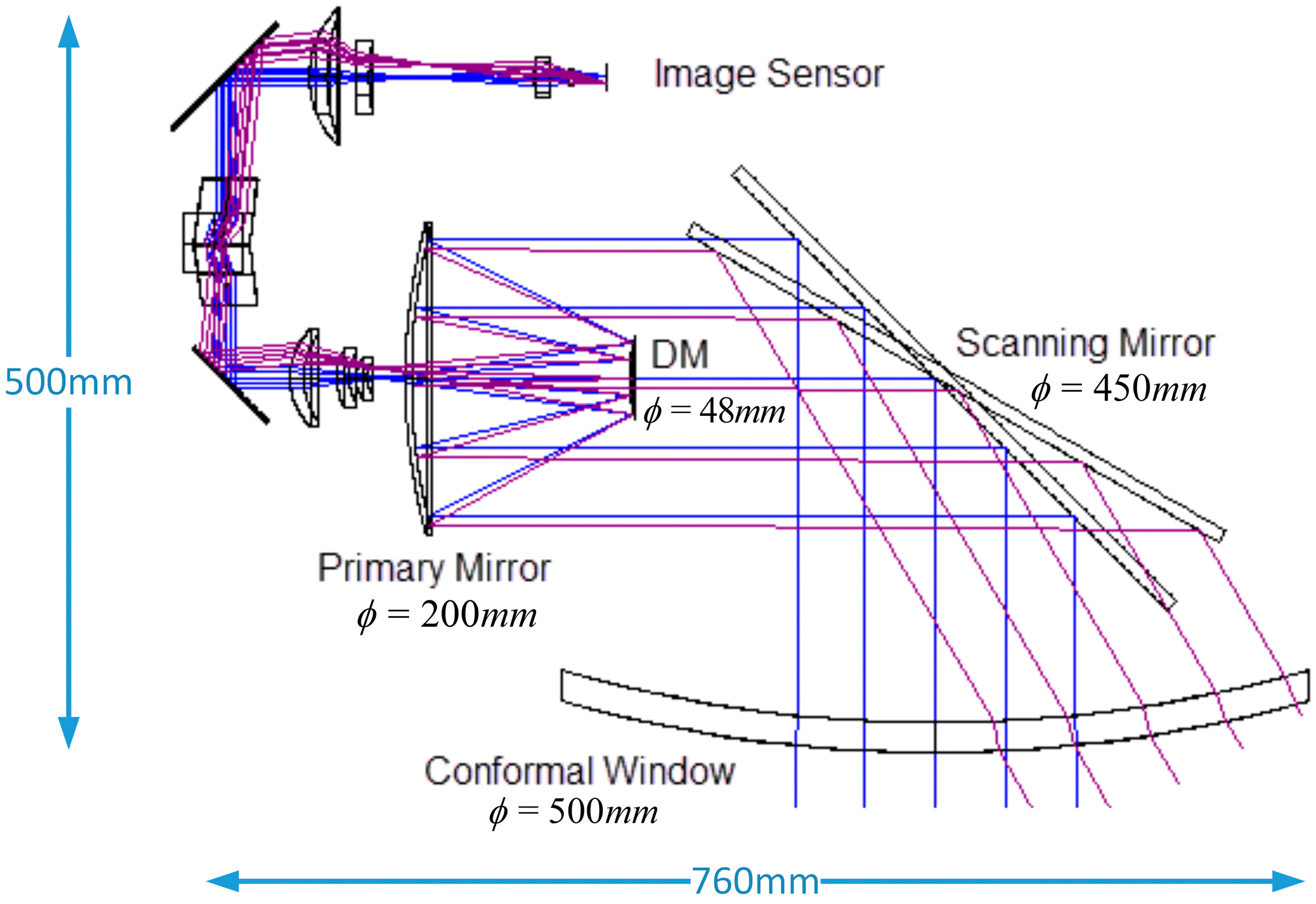
2. Optical System
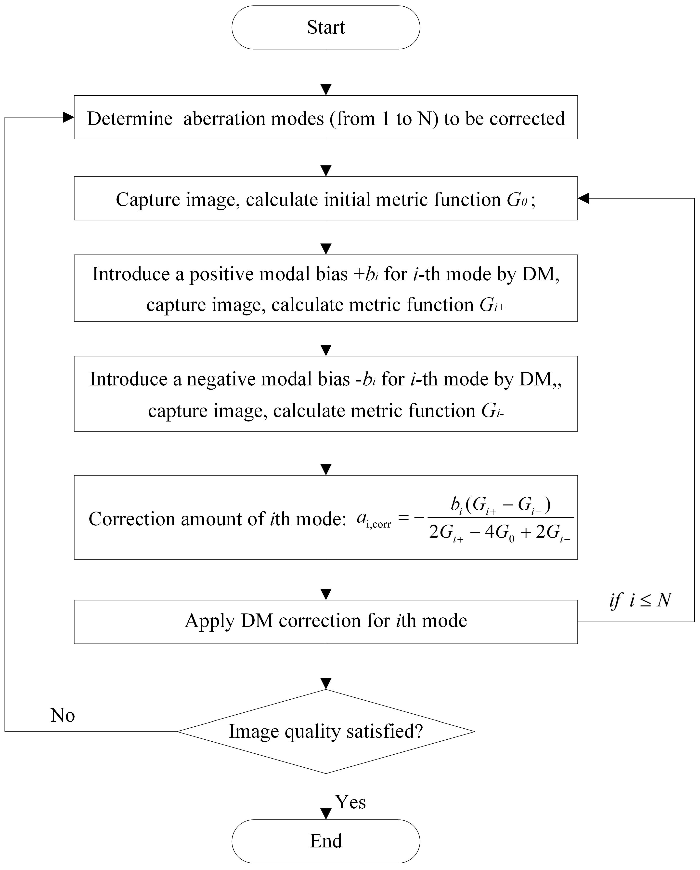
3. Principle of Model-Based WSLAO
4. Algorithm Optimization and Simulation
4.1. Simulation Method
4.2. Optimized Dynamic Correction
4.3. Dynamic Correction Simulation
5. Experimental Demonstration
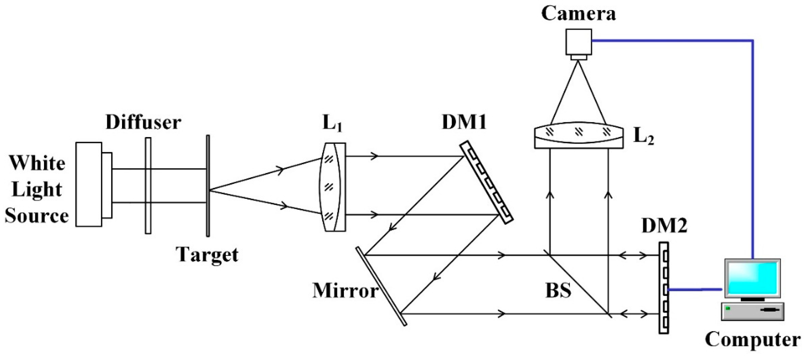
5.1. System Setup
5.2. System Error Clearance
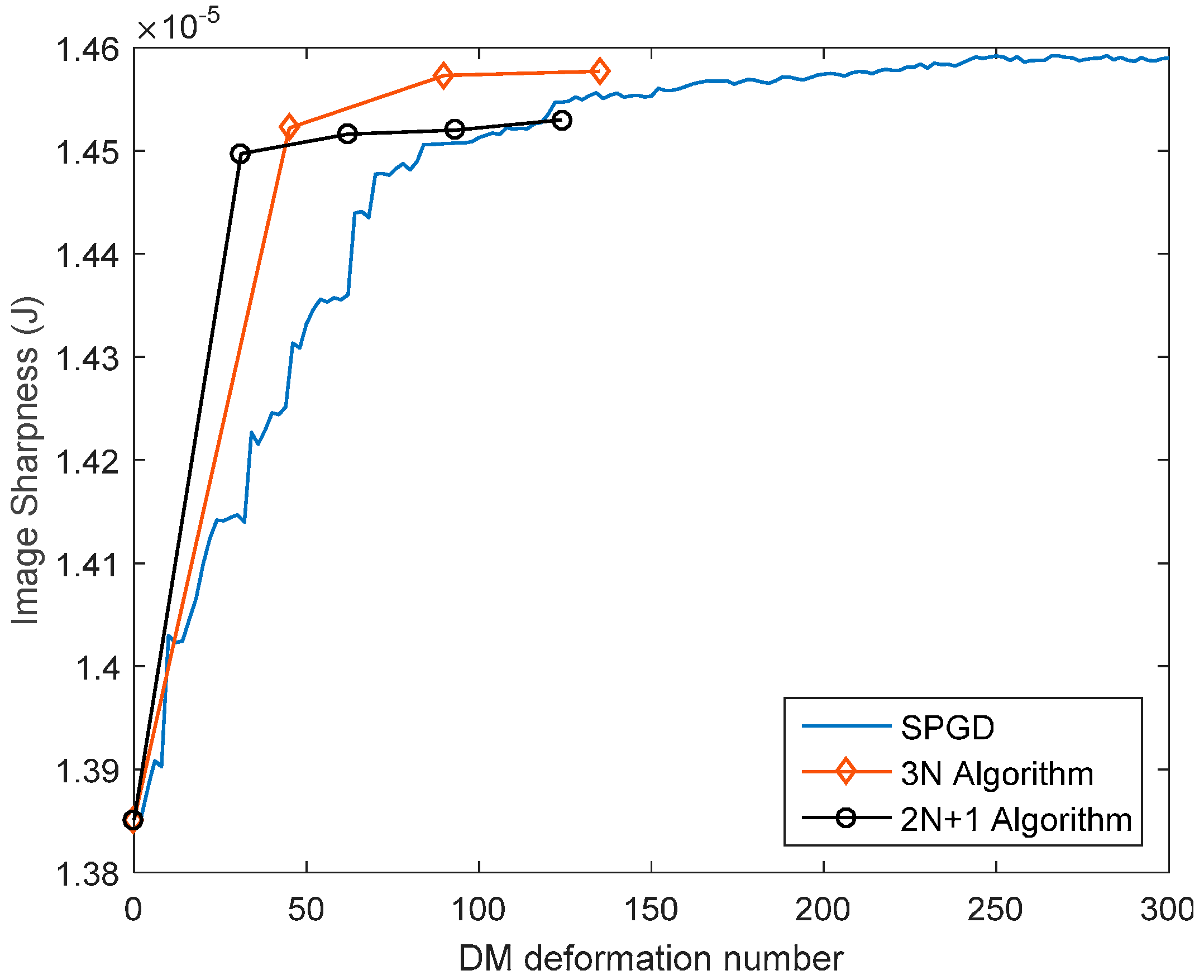
5.3. Dynamic Correction Results
6. Conclusions
Acknowledgments
Author Contributions
Conflicts of Interest
References
- Mills, J.P. Conformal Optics: Theory and Practice. In Proceedings of the Novel Optical Systems Design and Optimization IV, San Diego, CA, USA, 29 July 2001; pp. 101–107.
- Zhao, C.; Cui, Q.; Mao, S. Aberration and boresight error correction for conformal aircraft windows using the inner window surface and tilted fixed correctors. Appl. Opt. 2016, 55, 2626–2633. [Google Scholar] [CrossRef] [PubMed]
- Zhang, W.; Chen, S.; Hao, C.; Wang, H.; Zuo, B.; Fan, Z. Conformal dome aberration correction with gradient index optical elements. Opt. Express. 2014, 22, 3514–3525. [Google Scholar] [CrossRef] [PubMed]
- Zhang, W.; Zuo, B.; Chen, S.; Xiao, H.; Fan, Z. Design of fixed correctors used in conformal optical system based on diffractive optical elements. Appl. Opt. 2013, 52, 461–466. [Google Scholar] [CrossRef] [PubMed]
- Hao, Q.; Cheng, X.; Kang, J.; Jiang, Y. An image stabilization optical system using deformable freeform mirrors. Sensors 2015, 15, 1736–1749. [Google Scholar] [CrossRef] [PubMed]
- Li, Y.; Li, L.; Huang, Y.; Liu, J. Conformal optical design with combination of static and dynamic aberration corrections. Chin. Phys. B 2009, 18, 565–570. [Google Scholar]
- Li, Y.; Li, L.; Huang, Y.; Du, B. Correcting dynamic residual aberrations of conformal optical systems using AO technology. Chin. Phys. B 2009, 18, 2769–2773. [Google Scholar]
- Lombardo, M.; Serrao, S.; Devaney, N.; Parravano, M.; Lombardo, G. Adaptive optics technology for high-resolution retinal imaging. Sensors 2013, 13, 334–366. [Google Scholar] [CrossRef] [PubMed]
- Vorontsov, M.A.; Carhart, G.W. Adaptive optics based on analog parallel stochastic optimization: Analysis and experimental demonstration. J. Opt. Soc. Am. A 2000, 17, 1440–1453. [Google Scholar] [CrossRef]
- Gao, Q.; Jiang, Z.; Yi, S.; Xie, W.; Liao, T. Correcting the aero-optical aberration of the supersonic mixing layer with adaptive optics: concept validation. Appl. Opt. 2012, 51, 3922–3929. [Google Scholar] [CrossRef] [PubMed]
- Booth, M.J. Wave front sensor-less adaptive optics: A model-based approach using sphere packings. Opt. Express. 2006, 14, 1339–1352. [Google Scholar] [CrossRef] [PubMed]
- Débarre, D.; Booth, M.J.; Wilson, T. Image based adaptive optics through optimisation of low spatial frequencies. Opt. Express. 2007, 15, 8176–8190. [Google Scholar] [CrossRef] [PubMed]
- Dong, B.; Wang, R. Laser beam cleanup using improved model-based wavefront sensorless adaptive optics. Chin. Opt. Lett. 2016, 14, 031406. [Google Scholar] [CrossRef]
- Wei, H.; Su, G.J. Design and fabrication of a large-stroke deformable mirror using a gear-shape ionic-conductive polymer metal composite. Sensors 2012, 12, 11100–11112. [Google Scholar] [CrossRef] [PubMed]
- Hossain, M.M.; Bin, W.; Kong, S.H. Large-stroke convex micromirror actuated by electromagnetic force for optical power control. Opt. Express. 2015, 23, 28358–28368. [Google Scholar] [CrossRef] [PubMed]
- ALPAO Deformable Mirrors. Available online: http://www.alpao.com/adaptive-optics/deformable-mirrors.html (accessed on 20 June 2016).
- Tyson, R.K. Introduction to Adaptive Optics; SPIE Press: Bellingham, WA, USA, 2000. [Google Scholar]
- Conrad, R.A.; Wilcox, W.E.; Williams, T.H.; Michael, S.; Roth, J.M. Emulation of dynamic wavefront disturbances using a deformable mirror. Opt. Express. 2009, 17, 3447–3459. [Google Scholar] [CrossRef] [PubMed]
- Hao, C.; Chen, S.; Zhang, W.; Ren, J.H.; Li, C.; Pang, H.J.; Wang, H.H.; Liu, Q.; Wang, C.; Zou, H.Y.; et al. Comprehensive analysis of imaging quality degradation of an airborne optical system for aerodynamic flow field around the optical window. Appl. Opt. 2013, 52, 7889–7898. [Google Scholar] [CrossRef] [PubMed]
- Vogel, C.R.; Tyler, G.A.; Wittich, D.J. Spatial–temporal-covariance-based modeling, analysis, and simulation of aero-optics wavefront aberrations. J. Opt. Soc. Am. A 2014, 31, 1666–1679. [Google Scholar] [CrossRef] [PubMed]
- Goorskey, D.J.; Drye, R.; Whiteley, M.R. Dynamic modal analysis of transonic Airborne Aero-Optics Laboratory conformal window flight-test aero-optics. Opt. Eng. 2013, 52, 071414. [Google Scholar] [CrossRef]
- BMC Deformable Mirrors. Available online: http://www.bostonmicromachines.com/deformable-mirrors.html (accessed on 20 June 2016).


| Parameter | Value | Parameter | Value |
|---|---|---|---|
| Window surface type | Toroid | Window thickness (mm) | 20 |
| Window material | Germanium | Window diameter (mm) | 500 |
| Field of view (°) | ±0.25 | Field of regard (°) | ±30 |
| Primary mirror diameter (mm) | 200 | DM diameter (mm) | 48 |
| Working f-number | 2.8 | Working wavelength (μm) | 7.7–10.3 |
© 2016 by the authors; licensee MDPI, Basel, Switzerland. This article is an open access article distributed under the terms and conditions of the Creative Commons Attribution (CC-BY) license (http://creativecommons.org/licenses/by/4.0/).
Share and Cite
Dong, B.; Li, Y.; Han, X.-l.; Hu, B. Dynamic Aberration Correction for Conformal Window of High-Speed Aircraft Using Optimized Model-Based Wavefront Sensorless Adaptive Optics. Sensors 2016, 16, 1414. https://doi.org/10.3390/s16091414
Dong B, Li Y, Han X-l, Hu B. Dynamic Aberration Correction for Conformal Window of High-Speed Aircraft Using Optimized Model-Based Wavefront Sensorless Adaptive Optics. Sensors. 2016; 16(9):1414. https://doi.org/10.3390/s16091414
Chicago/Turabian StyleDong, Bing, Yan Li, Xin-li Han, and Bin Hu. 2016. "Dynamic Aberration Correction for Conformal Window of High-Speed Aircraft Using Optimized Model-Based Wavefront Sensorless Adaptive Optics" Sensors 16, no. 9: 1414. https://doi.org/10.3390/s16091414
APA StyleDong, B., Li, Y., Han, X.-l., & Hu, B. (2016). Dynamic Aberration Correction for Conformal Window of High-Speed Aircraft Using Optimized Model-Based Wavefront Sensorless Adaptive Optics. Sensors, 16(9), 1414. https://doi.org/10.3390/s16091414