Communication

A Touch Sensing Technique Using the Effects of Extremely Low Frequency Fields on the Human Body

1
Graduate School of Engineering, Nagoya University, Nagoya 464-8603, Japan
2
Electrical Engineering Department, Faculty of Engineering, The British University in Egypt, Cairo 11837, Egypt
*
Author to whom correspondence should be addressed.
Sensors 2016, 16(12), 2049; https://doi.org/10.3390/s16122049
Submission received: 17 August 2016 / Revised: 31 October 2016 / Accepted: 21 November 2016 / Published: 2 December 2016
(This article belongs to the Section Physical Sensors)

Abstract

:
Touch sensing is a fundamental approach in human-to-machine interfaces, and is currently under widespread use. Many current applications use active touch sensing technologies. Passive touch sensing technologies are, however, more adequate to implement low power or energy harvesting touch sensing interfaces. This paper presents a passive touch sensing technique based on the fact that the human body is affected by the surrounding extremely low frequency (ELF) electromagnetic fields, such as those of AC power lines. These external ELF fields induce electric potentials on the human body—because human tissues exhibit some conductivity at these frequencies—resulting in what is called AC hum. We therefore propose a passive touch sensing system that detects this hum noise when a human touch occurs, thus distinguishing between touch and non-touch events. The effectiveness of the proposed technique is validated by designing and implementing a flexible touch sensing keyboard.

1. Introduction

Touch sensing technologies are used in many applications, comprising smartphones and tablets, laptops, information kiosks, etc. Touch screens are very intuitive and easy to use; they also save space, because of their screen and interface spatial integration. Many touch sensing technologies have therefore been developed for commercial purposes. Examples include technologies based on infra-red sensing elements [1,2,3,4], resistive [5,6] and capacitive touch panels [7,8,9], cameras [10], the acoustic and deflection characteristics of touch panels [11,12,13], and others [14,15,16]. One of the widely used techniques is the mutual capacitive method, which is used in almost all smartphones and tablets [17]. In this method, the touch screen interface is built or constructed by rows and columns of transparent wires made from indium tin oxide. The row and column wires are separated by a thin glass layer. Each row/column is electronically charged by an individual driver circuit. When the user touches the screen at a specific position, the capacitance at the intersection between the row and the column at this position changes; the point of pressure on the panel can thus by localized by scanning all the other non-energized rows and columns and computing the capacitance at all intersections [18].
Most of the aforementioned commercially available touch sensing techniques can be classified as active sensing techniques, because touch detection depends on transmitting and receiving a signal that is perturbed by a touch. For example, in the surface acoustic wave (SAW) touch sensing, transmitters mounted on the edges of the touch screen emit sound waves that propagate through the touch screen to be received by ultrasound receivers. At the onset of touch, the human finger absorbs some of the sound waves. As a result, the signal characteristics at the receiver are altered, as the signal’s power is reduced [19]. This change in signal power is used to detect a touch. Therefore, active touch sensing techniques such as SAW use a transmitter and a receiver. On the other hand, passive sensing involves the measurement of an external signal—which is not predefined—resulting from a touch. An example of a passive touch technique is acoustic pulse recognition where sound wave receivers are used to detect a touch and no transmitters are required. Passive sensing approaches are usually low power techniques, because processing and sensing occur only at the onset of touch; in contrast, active sensing involves the continuous transmission, reception, and measurement of the detected signal, and further requires higher power levels. Some low power passive touch sensing techniques have been proposed, for which driver circuits are not required. However, some of these techniques may not be suitable to detect the touch of human fingers [20,21]. Other passive touch sensing techniques are based on piezoelectric and pyroelectric effects, as well as bending waves that propagate through the touch panel [22,23]. Nonetheless, they lack the “touch and hold” capability, which is an essential manipulation feature in touch sensing interfaces [17].
In this study, we focus on another sensing technique, called humantenna. This touch technique detects the voltage induced on the human body by nearby AC power lines. The humantenna touch sensing technique has been used for gesture recognition and as an ultralow power human body motion detector [24,25,26]. However, with the exception of our previous proposals [27,28], few passive touch sensing interfaces based on this technique have been proposed as viable alternatives to build practical devices such as keyboards or touch screens. In this paper, we propose and explore the humantenna touch technique as a touch sensing interface. The device based on this technique is passive, and requires only a signal conditioning circuit. In particular, we present a flexible touch keyboard design as an example of a low power passive touch interface based on the humantenna technique.
The rest of this paper is organized as follows. In Section 2, we introduce the operating principle of the proposed sensing technique and the associated detection scheme. In Section 3, we present the design and implementation of a keyboard based on the proposed touch sensing technique. Section 4 discusses the results of the tests made to the developed keyboard, and Section 5 concludes the paper and discusses future work.

2. Operation Principle

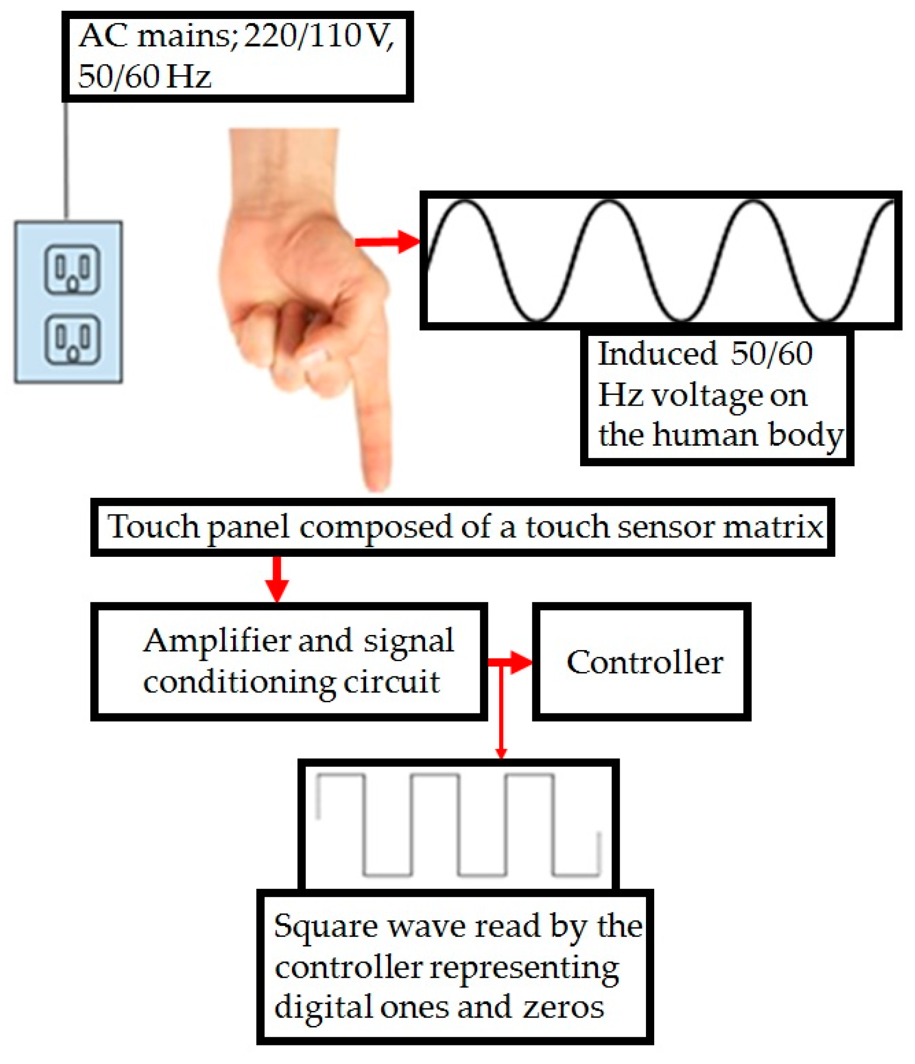
2.1. Effects of External Electric Fields on the Human Body

Various sources of electric and magnetic fields are present in our daily environment, such as geomagnetic sources, electrical power (AC) generation and transmission, domestic appliances, industrial equipment, telecommunications, and media broadcasting. All these sources contribute to a daily exposure to a very diverse mix of electromagnetic waves, including extremely low frequency electric and magnetic fields. Moreover, the human body’s nervous system induces the so-called biopotentials on the outer skin layer, which are in the low-frequency range [29]. The combined effect of both phenomena (external electromagnetic fields and biopotentials) creates a resultant potential on the human body that can be detected and used as a touch sensing trigger.
The voltage induced from biopotentials and the other mentioned sources of electromagnetic fields on the human body is negligible when compared with the voltage induced by the electromagnetic fields of nearby AC power lines [30]. Therefore, when developing touch sensors, the focus is placed on this latter external source of electromagnetic fields. This touch sensing technique is known as humantenna [24].
The frequency of AC power lines is very low (50/60 Hz). Therefore, a quasi-static approximation can be used, and the effects of the external electric and magnetic fields on the human body can be computed independently [31]. The magnetic permeability of the human body is similar to that of free space [32]. As a consequence, the magnetic field’s effect on the human body can be neglected, when considering indoor applications. Therefore, the electric fields produced by AC power lines are the main contributors to the voltage induced on the human body. The electric field induced by external electric fields can be obtained with the following equation:
E n o r m a l , b i o = ω E L F   ε o σ b i o E n o r m a l , a i r
where Enormal,bio and Enormal,air are the normal components of the electric field in the human body and air, respectively, and ωELF, σbio, and εo are the AC line frequency, whole body conductivity, and electrical permittivity of space, respectively [33]. This equation can be used to calculate the value of the induced potential on the human body when exposed to 50/60 Hz fields from typical 220/110 V AC appliances, the major sources of electric fields in common daily life.

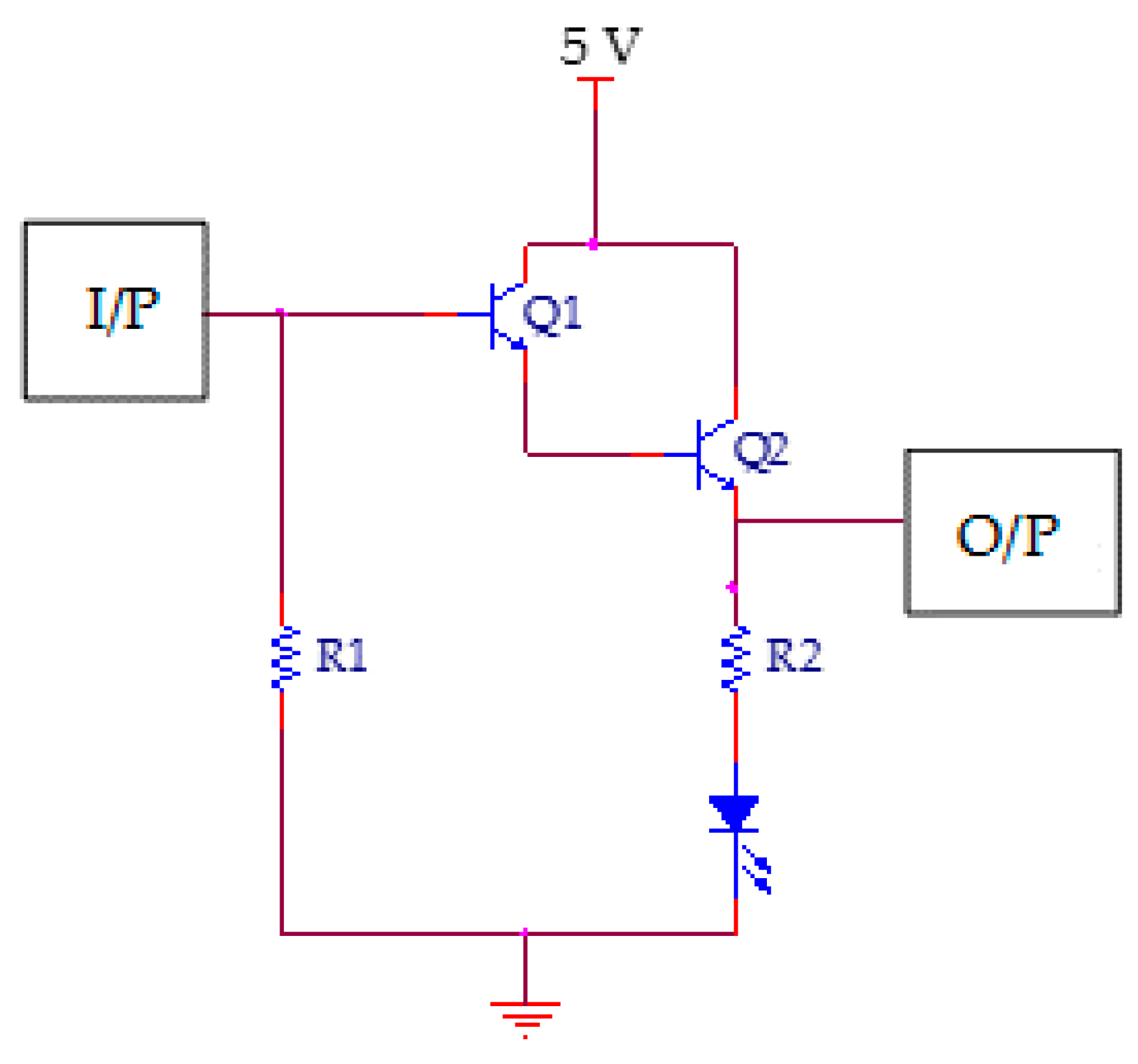
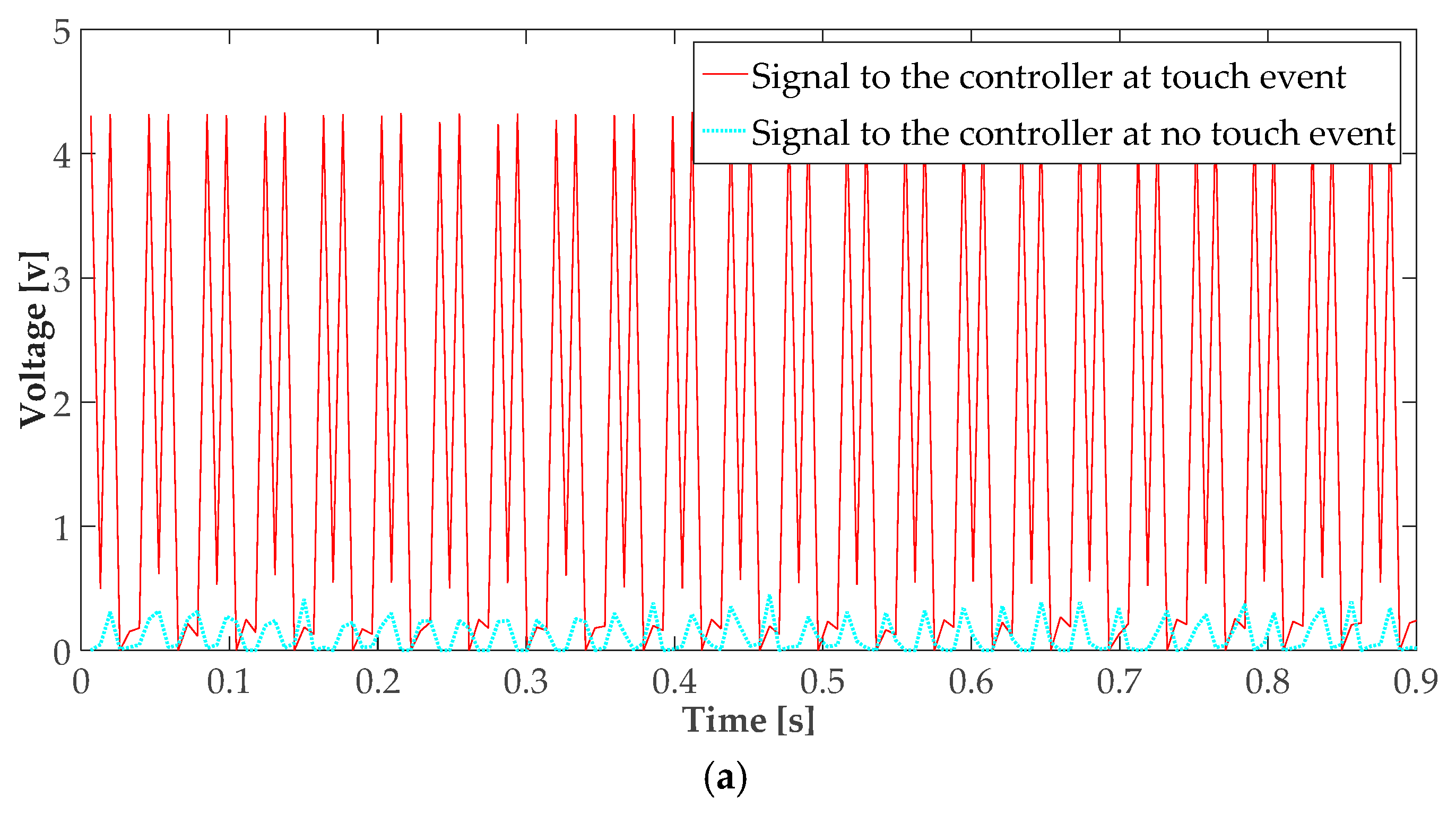
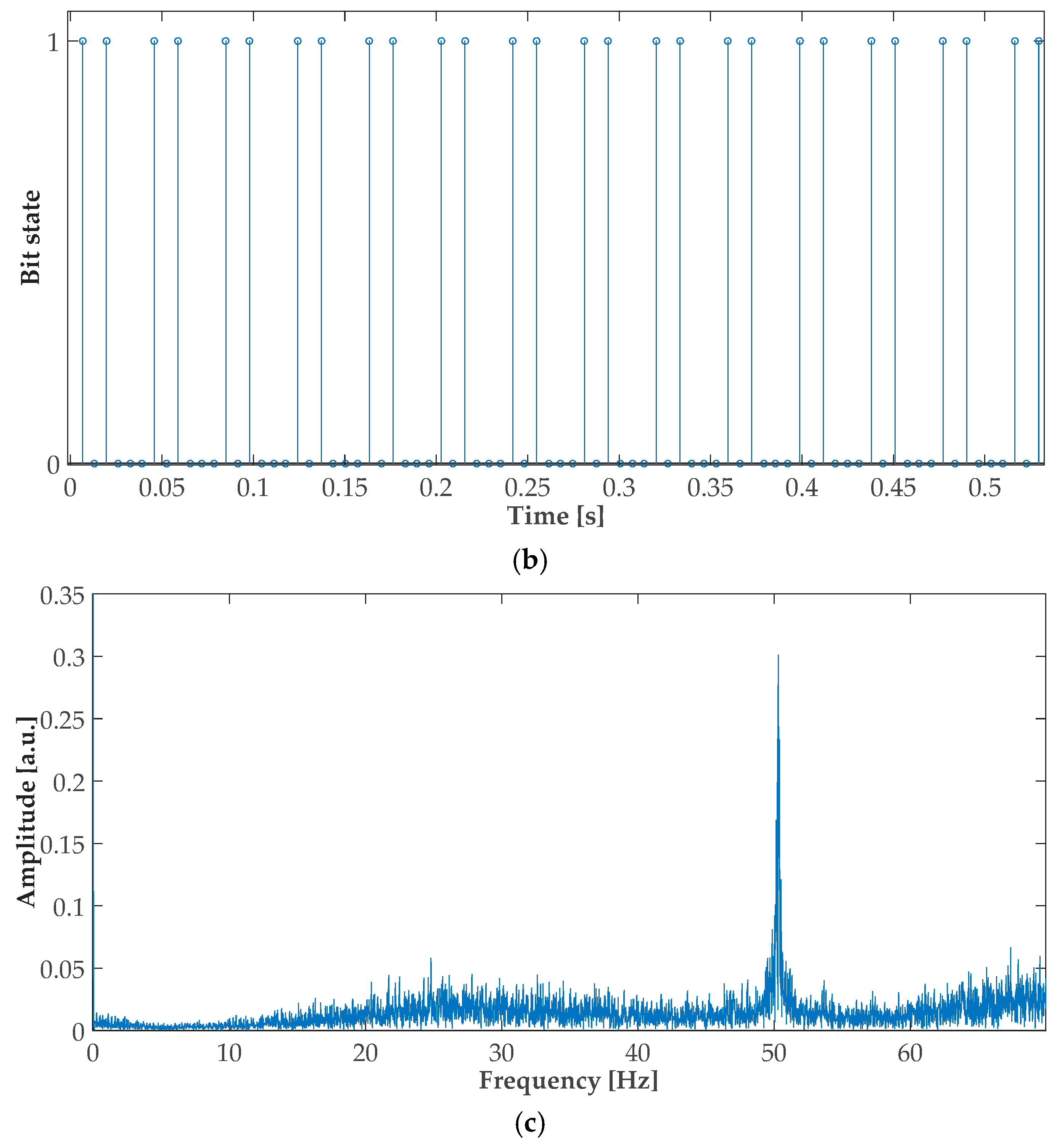
2.2. AC Hum Touch Signal Acquisition and Processing

A diagram of the humantenna approach as implemented here can be seen in Figure 1: a human body touches the surface of a panel, and the resulting AC signal is then amplified and conditioned for processing by a controller.
The detection circuit must be capable of processing low power sinusoidal signals. Therefore, a Darlington amplifier was used, because of its good sensitivity, linearity, and large amplification factor (typically of several hundreds or thousands A/A) [34]. The whole amplifying circuit is composed of one Darlington pair, two resistors, and an LED, as shown in Figure 2. The LED is used for indication purposes, with R2 (50 Ω) being used for LED protection. The branch containing R2 and the LED is placed in parallel with the controller input, whereas R1 (1 MΩ) is used as a pull-down resistor to nullify the parasitic effects in the circuit.
Most controllers have a small number of analogue inputs. Therefore, for convenience, digital controller inputs were used. In addition, analogue processing would imply analogue-to-digital (A/D) conversions and filtering (implying either extra modules, or a more advanced controller), whereas the use of digital inputs avoids the aforementioned needs, allowing faster and simpler processing algorithms. Therefore, leveraging the fact that the analog amplitude information is not necessary for the intended detection, both the electrical signal conditioning and the processing algorithm were designed such that the obtained signals could be connected directly to the controller’s digital input pins. Consequently, the signal delivered to the controller at each input pin is a square wave oscillating between logic zero and logic one, instead of an analogue sinusoidal wave.
Figure 3a–c show the signal waveforms at the output of the amplifier in the cases of touch and no touch, the logic square wave read by the controller in the case of a touch event, and the frequency spectrum of the touch signal, respectively. As shown in Figure 3a, the input signal to the controller in the case of a touch event has a maximum voltage in excess of 4 V, whereas the maximum signal voltage in the no-touch case is below 0.5 V. For a typical controller with a supply voltage of 5 V, the maximum allowable voltage for logic zero is 1 V, whereas the threshold voltage for logic one is 3.5 V [35].
A timer is used in the controller to differentiate between touch and no-touch situations. As seen in Figure 3b, a touch-induced signal is received by the controller as a train of logic one impulses, whereas the no-touch situation corresponds to a stream of logic zero. A touch is preliminarily detected whenever a logic one is detected. When a logic zero is detected after a logic one, the timer is activated. If only logic zero is read within the specific timer duration, a final no-touch decision is made; otherwise, if further logic one is detected within the timer duration, the existence of a touch is confirmed, and a final decision (touch detection) is accordingly made. If a logic one is detected within the subsequent timer period, a “touch and hold” operation is detected. The timer duration was chosen to be 30 ms, which is a one-and-a-half period of a 50 Hz signal. Figure 3b shows that the maximum time between two consecutive ones is 26.1 ms.

3. Design and Implementation of a Keyboard Based on the Proposed Touch Sensing Technique

Using the proposed touch sensing technique, a touch keyboard was designed and implemented. The keyboard is comprised of a touch keypad interface, a signal conditioning circuit and a controller. A controller capable of supporting universal serial bus (USB) protocols was selected, both for convenience and to have enough digital input channels (a few tens of channels are needed in this application).
To allow users to directly touch the keyboard’s interface without the need for an intermediate medium, the proposed keyboard interface uses a matrix of dry electrodes [36]. The interface consists mainly of bare copper wires and insulators, which are arranged in four layers, as shown in Figure 4a. Both the copper wires and the insulator layer are 1-mm thick. The bottom transparent layer, which is referred to as the substrate layer, is a standard plastic sheet. The next layer, which is referred to as the row layer, is composed of six horizontal bare copper wires. The third layer contains 15 vertical insulators, whereas the last layer—referred to as the column layer—is composed of vertical bare copper wires, as shown by the dashed lines in Figure 4a. The construction process is comprised of three steps. First, the row layer is mounted (with equidistant rows) on the plastic substrate, and fixed in place by a cyanoacrylate adhesive. An insulator layer also made of cyanoacrylate is then mounted on top of the row layer. Finally, the column layer is mounted on the insulator layer. With this setup, the columns and rows form a matrix of coordinates. Each touch button is the intersection of a row and a column; a total of 90 distinct inputs are therefore provided. When touched by a human user, a 50 Hz signal will be induced in the corresponding row and column, thus enabling touch detection and the identification of the touched intersection.
The proposed structure guarantees a unique identification of the activated touch button, because no button is represented by more than one row and one column. Moreover, this interface design has some desirable features: it is flexible and easy to store, as shown in Figure 4b; its size can easily be customized to the application; finally, it can be easily mounted on any surface, as shown in Figure 5.
The whole detection and signal conditioning circuit consisted of the 21 Darlington cells for the 21 input sensors (15 columns and 6 rows). The controller can determine the touch position by simply determining on which inputs the touch signal is present, and comparing the input pattern with a predefined look-up table. The operational algorithm is therefore very simple, and the inputs are read as standard digital signals, which is a major advantage of this keyboard implementation.

4. Testing the Keyboard

To show the response of the proposed technique to noisy signals (which are not touch events), Figure 6a shows a comparison of the sensor voltage during a touch event with the one caused by a finger proximity at various distances from the keyboard (non-touch events). The minimum detectable voltage appeared at a distance below 0.5 mm from the keyboard interface, which indicates that the implemented keyboard is sensitive only to touch events.
To characterize the hysteresis phenomenon, Figure 6a shows the voltage readings obtained when the user’s finger is both approaching and retreating from the keyboard interface. For the implemented keyboard, the hysteresis error—the maximum difference in the recorded voltage values as the finger approached and backed away from the keyboard—was found to be less than 1%. In addition, the keyboard was tested in the various conditions and environments where its use is most expected (e.g., libraries, study rooms, residential units and laboratories). The keyboard’s sensitivity and performance showed no major variations under the different environmental conditions, as shown in Figure 6b.
The repeatability error for the implemented keyboard—defined as the maximum difference between sensor outputs recorded for the same input values, under the same conditions—was less than 6.5% for all the conducted tests, with a relative standard deviation value below 5.7%.
All the previous measurements and statistical data show the potential of the proposed touch sensing technique as a promising technology, both in terms of reliability and of cost-effectiveness, when compared to the other popular touch sensing techniques mentioned in the Introduction.

5. Conclusions and Future Work

In this paper, a novel touch sensing technique was proposed, based on the detection of the voltage induced on the human body by the electric fields of AC power lines.
To demonstrate the effectiveness of the proposed technique, a touch sensing keyboard was designed and implemented. The keyboard was constructed from simple components (a plastic interface, Darlington pair amplifiers, and a typical controller), and therefore did not require complex or expensive hardware. Moreover, the implemented keyboard has many desirable features: it is highly flexible, it is shock-, dust-, and water-resistant, and last but foremost it has very low implementation and operation costs. Taking into consideration that the proposed touch technique is passive and does not therefore require external generators, other possible important applications may include touch floors and safety sensors [37,38,39].
To extend our method to other contexts beyond the detection of binary events (e.g., to the localization of touch on an object surface [39]), the repeatability error mentioned above should be specifically considered. Possible causes for this error can be found in the existence of other ELF waves such as Schumann resonance [24], switched mode power supply interference noise [40], other external noises imposed by the main supply line [25], and biopotential signals [33]. In future work, the authors will investigate possible solutions to this problem, such as using a power supply with a higher-quality factor and lower total harmonic distortion (THD) to remove the power source-induced noises, applying a high quality factor band pass filter for the 48 to 62 Hz frequency band, and/or using other amplifier with lower THD and thermal noise. Furthermore, the precise energy consumption of our technique is also a topic for further investigation.

Acknowledgments

This study was partially funded by MEXT Kakenhi (15H05923).

Author Contributions

Hatem Elfekey and Hany Ayad Bastawrous contributed equally to the work. Hatem Elfekey, Hany Ayad Bastawrous, and Shogo Okamoto were involved in the technical discussions and manuscript refinement.

Conflicts of Interest

The authors declare no conflict of interest.

Abbreviations

The following abbreviations are used in this manuscript:
ELFExtremely low frequency
LEDLight emitting diode
USBUniversal serial bus

References

  1. Lee, B.; Hong, I.; Uhm, Y.; Park, S. The multi-touch system with high applicability using tri-axial coordinate infrared LEDs. IEEE Trans. Consum. Electron. 2009, 55, 2416–2424. [Google Scholar] [CrossRef]
  2. Lim, S.-C.; Shin, J.; Kim, S.-C.; Park, J. Expansion of smart watch touch interface from touchscreen to around device interface using infrared line image sensors. Sensors 2015, 15, 16642–16653. [Google Scholar] [CrossRef] [PubMed]
  3. Han, J.H.; Lee, K.-H.; Han, W.H. A Conclusive Role of Ordinary Transmission for an effective FTIR Touch Screen. In Proceedings of the IEEE International Conference on Industrial Technology, Busan, Korea, 26 February–1 March 2014; pp. 583–588.
  4. Kim, Y.; Park, S.; Park, S.K.; Yun, S.; Kyung, K.-U.; Sun, K. Transparent and flexible force sensor array based on optical waveguide. Opt. Express 2012, 20, 14486–14493. [Google Scholar] [CrossRef] [PubMed]
  5. Shikida, M.; Asano, K. A flexible transparent touch panel based on ionic liquid channel. IEEE Sens. J. 2013, 13, 3490–3495. [Google Scholar] [CrossRef]
  6. Kamali, B. Touch-screen Displays. In Instrument Engineers’ Handbook—Process Control and Optimization, 4th ed.; Lipták, B.G., Ed.; CRC Press: Boca Raton, FL, USA, 2006; pp. 845–853. [Google Scholar]
  7. Nakamura, T.; Yamamoto, A. Interaction force estimation on a built-in position sensor for an electrostatic visuo-haptic display. ROBOMECH J. 2016, 3, 1–11. [Google Scholar] [CrossRef]
  8. Kim, W.; Oh, H.; Kwak, Y.; Park, K.; Ju, B.-K.; Kim, K. Development of a carbon nanotube-based touchscreen capable of multi-touch and multi-force sensing. Sensors 2015, 15, 28732–28741. [Google Scholar] [CrossRef] [PubMed]
  9. Wang, B.; Long, J.; Teo, K.H. Multi-channel capacitive sensor arrays. Sensors 2016, 16, 150. [Google Scholar] [CrossRef] [PubMed]
  10. Chen, Y.-L.; Liang, W.-Y.; Chiang, C.-Y.; Hsieh, T.-J.; Lee, D.-C.; Yuan, S.-M.; Chang, Y.-L. Vision-based finger detection, tracking, and event identification techniques for multi-touch sensing and display systems. Sensors 2011, 11, 6868–6892. [Google Scholar] [CrossRef] [PubMed]
  11. Reis, S.; Correia, V.; Martins, M.; Barbosa, G.; Sousa, R.M.; Minas, G.; Lanceros-Mendez, S.; Rocha, J.G. Touchscreen Based on Acoustic Pulse Recognition with Piezoelectric Polymer Sensors. In Proceedings of the IEEE International Symposium on Industrial Electronics, Bari, Italy, 4–7 July 2010.
  12. Katsuki, T.; Nakazawa, F.; Sano, S.; Takahashi, Y.; Satoh, Y. A compact and High Optical Transmission SAW Touch Screen with ZnO Thin-Film Piezoelectric Transducers. In Proceedings of the 2003 IEEE Symposium on Ultrasonics, Honolulu, HI, USA, 5–8 October 2003; pp. 821–824.
  13. Liu, Y.; Nikolovski, J.P.; Mechbal, N.; Hafez, M.; Vergé, M. An acoustic multi-touch sensing method using amplitude disturbed ultrasonic wave diffraction patterns. Sens. Actuators A Phys. 2010, 162, 394–399. [Google Scholar] [CrossRef] [Green Version]
  14. Kurita, K.; Fujii, Y.; Shimada, K. A new technique for touch sensing based on measurement of current generated by electrostatic induction. Sens. Actuators A Phys. 2011, 170, 66–71. [Google Scholar] [CrossRef]
  15. Shinoda, H.; Chigusa, H.; Makino, Y. Flexible tactile sensor skin using wireless sensor elements coupled with 2D microwaves. J. Robot. Mechatron. 2010, 22, 784–789. [Google Scholar]
  16. Dahiya, R.S.; Adami, A.; Collini, C.; Lorenzelli, L. POSFET tactile sensing arrays using CMOS technology. Sens. Actuators A Phys. 2012, 47, 894–897. [Google Scholar] [CrossRef]
  17. Walker, G. A review of technologies for sensing contact location on the surface of a display. J. Soc. Inf. Disp. 2012, 20, 413–440. [Google Scholar] [CrossRef]
  18. Tsuji, S.; Kohama, T. A layered 3D touch screen using capacitance measurement. IEEE Sens. J. 2014, 14, 3040–3045. [Google Scholar] [CrossRef]
  19. Hashimoto, K.; Nakamoto, T. Tiny olfactory display using surface acoustic wave device and micropumps for wearable applications. IEEE Sens. J. 2016, 16, 4974–4980. [Google Scholar] [CrossRef]
  20. Sample, A.P.; Yeager, D.J.; Smith, J.R. A capacitive Touch Interface for Passive RFID. In Proceedings of the IEEE International Conference on RFID, Orlando, FL, USA, 27–28 April 2009; pp. 103–109.
  21. Andò, B.; Baglio, S.; Marletta, V.; Pistorio, A. A contactless Inkjet Printed Passive Touch Sensor. In Proceedings of the IEEE International Instrumentation and Measurement Technology Conference, Montevideo, Uruguay, 12–15 May 2014; pp. 1638–1642.
  22. Sarwar, M.; Dobashi, Y.; Glitz, E.; Farajollahi, M.; Mirabbasi, S.; Naficy, S.; Spinks, G.M.; Madden, J.D. Transparent and Conformal ‘Piezoionic’ Touch Sensor. In Proceedings of the Electroactive Polymer Actuators and Devices, San Diego, CA, USA, 9–12 March 2015.
  23. Rendl, C.; Greindl, P.; Haller, M.; Zirkl, M.; Stadlober, B.; Hartmann, P. PyzoFlex: Printed Piezoelectric Pressure Sensing Foil. In Proceedings of the 25th Annual ACM Symposium on User Interface Software and Technology, Cambridge, MA, USA, 7–10 October 2012; pp. 509–518.
  24. Cohn, G.; Morris, D.; Patel, S.N.; Tan, D. Humantenna: Using the Body as an Antenna for Real-Time Whole-Body Interaction. In Proceedings of the SIGCHI Conference on Human Factors in Computing Systems, Austin, TX, USA, 5–10 May 2012; pp. 1901–1910.
  25. Cohn, G.; Morris, D.; Patel, S.N.; Tan, D. Your Noise is My Command: Sensing Gestures Using the Body as an Antenna. In Proceedings of the SIGCHI Conference on Human Factors in Computing Systems, Vancouver, BC, Canada, 7–12 May 2011; pp. 791–800.
  26. Cohn, G.; Gupta, S.; Lee, T.-J.; Morris, D.; Smith, J.R.; Reynolds, M.S.; Tan, D.S.; Patel, S.N. An Ultra-Low-Power Human Body Motion Sensor Using Static Electric Field Sensing. In Proceedings of the ACM Conference on Ubiquitous Computing, Pittsburgh, PA, USA, 5–8 September 2012; pp. 99–102.
  27. Elfekey, H.M.; Bastawrous, H.A. Design and Implementation of a New Thin Cost Effective AC Hum Based Touch Sensing Keyboard. In Proceedings of the IEEE International Conference on Consumer Electronics, Las Vegas, NV, USA, 11–14 January 2013; pp. 602–605.
  28. Elfekey, H.M.; Bary, E.M.A.; Bastawrous, H.A. Flexible ITO-Free Touch Panel Based on The Effects of Extremely Low Frequency Electromagnetic Fields. In Proceedings of the IEEE International Symposium on Consumer Electronics, Madrid, Spain, 24–26 June 2015; pp. 1–2.
  29. Wang, T.-Y.; Liu, L.-H.; Peng, S.-Y. A power-efficient highly linear reconfigurable biopotential sensing amplifier using gate-balanced pseudoresistors. IEEE Trans. Circuits Syst. II 2015, 62, 199–203. [Google Scholar] [CrossRef]
  30. Ma, C.-T.; Mak, P.-I.; Vai, M.-I.; Mak, P.-U.; Pun, S.-H.; Feng, W.; Martins, R.P. Frequency-bandwidth-tunable powerline notch filter for biopotential acquisition systems. IEEE Electron. Lett. 2009, 45, 197–199. [Google Scholar] [CrossRef]
  31. Hoang, L.H.; Scorretti, R.; Burais, N.; Voyer, D. Numerical dosimetry of induced phenomena in the human body by a three-phase power line. IEEE Trans. Magn. 2009, 45, 1666–1669. [Google Scholar] [CrossRef]
  32. Scorretti, R.; Burais, N.; Fabregue, O.; Nicolas, A.; Nicolas, L. Computation of the induced current density into the human body due to relative LF magnetic field generated by realistic devices. IEEE Trans. Magn. 2004, 40, 643–646. [Google Scholar] [CrossRef]
  33. Peratta, C.; Peratta, A. Modelling the Human Body Exposure to ELF Electric Fields; WIT Press: Billerica, UK, 2010. [Google Scholar]
  34. Nikandish, G.; Medi, A. Design and analysis of broadband Darlington amplifiers with bandwidth enhancement in GaAs pHEMT Technology. IEEE Trans. Microw. Theory 2014, 62, 1705–1715. [Google Scholar] [CrossRef]
  35. Atmel, 8-bit Microcontroller with 16/32 Bytes of ISP Flash and USB Controller, ATmega16U4 Datasheet, November, 2014. Available online: http://www.atmel.com/images/doc7593.pdf (accessed on 15 May 2016).
  36. Lourenço, A.; Silva, H.; Santos, D.P.; Fred, A. Towards a Finger Based ECG Biometric System. In Proceedings of the International Conference on Bio-inspired Systems and Signal Processing, Rome, Italy, 26–29 January 2011.
  37. Elfekey, H.M.; Maximous, G.S.; Bastawrous, H.A. 3D Human Proximity Sensor Based on the AC Hum Effect. In Proceedings of IEEE 5th Global Conference on Consumer Electronics, Kyoto, Japan, 11–14 October 2016; pp. 610–611.
  38. Elfekey, H.M.; Bastawrous, H.A. Granite-based touch-sensing floor for machinery safety and exergaming. In Proceedings of the IEEE 4th Global Conference on Consumer Electronics, Osaka, Japan, 27–30 October 2015; pp. 593–594.
  39. Elfekey, H.M.; Okamoto, S. Turning surfaces into touch panels: A Granite touch panel. Unpublished work. 2016. [Google Scholar]
  40. Shin, H.; Ko, S.; Jang, H.; Yun, I.; Lee, K. A 55 dB SNR with 240 Hz frame scan rate mutual capacitor 30 × 24 touch-screen panel read-out IC using code-division multiple sensing technique. In Proceedings of the IEEE International Solid-State Circuits Conference Digest of Technical Papers, San Francisco, CA, USA, 17–21 February 2013; pp. 388–389.
Figure 1. Operation principle of a touch sensing device using the humantenna approach.
Sensors 16 02049 g001
Figure 2. Amplifier cell schematic.
Sensors 16 02049 g002
Figure 3. Touch signal characteristics. (a) Input signal to the controller before and after the touch event; (b) Digital signal received by the controller in the case of a touch event; (c) Frequency spectrum of the signal resulting from the touch event.
Sensors 16 02049 g003aSensors 16 02049 g003b
Figure 4. Flexible layered keyboard. (a) Layer structure; (b) Flexibility demonstration.
Sensors 16 02049 g004
Figure 5. Complete keyboard structure being tested in the laboratory.
Sensors 16 02049 g005
Figure 6. Voltage magnitude vs. distance between finger and keyboard. (a) Voltage detected while approaching and backing away from the keyboard; (b) Voltage detected in various environments.
Sensors 16 02049 g006

