
A New Indoor Positioning System Architecture Using GPS Signals

Abstract
:1. Introduction
2. System Structure
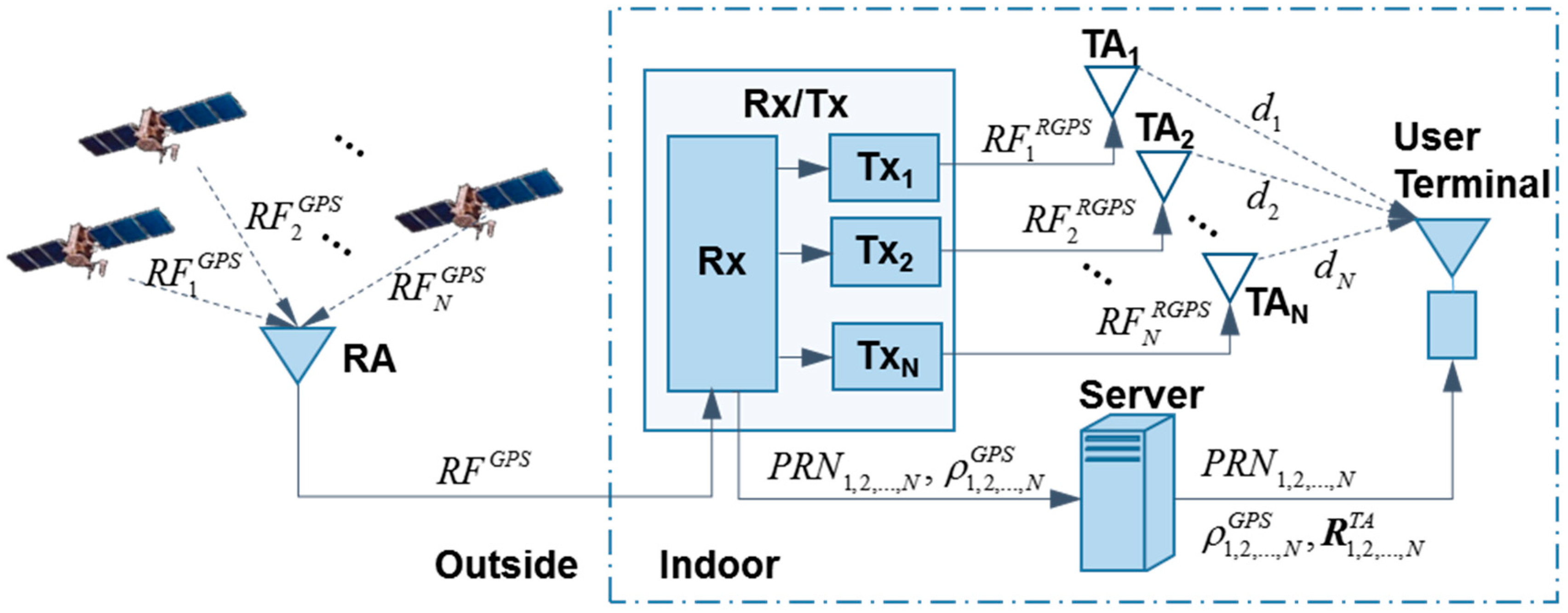
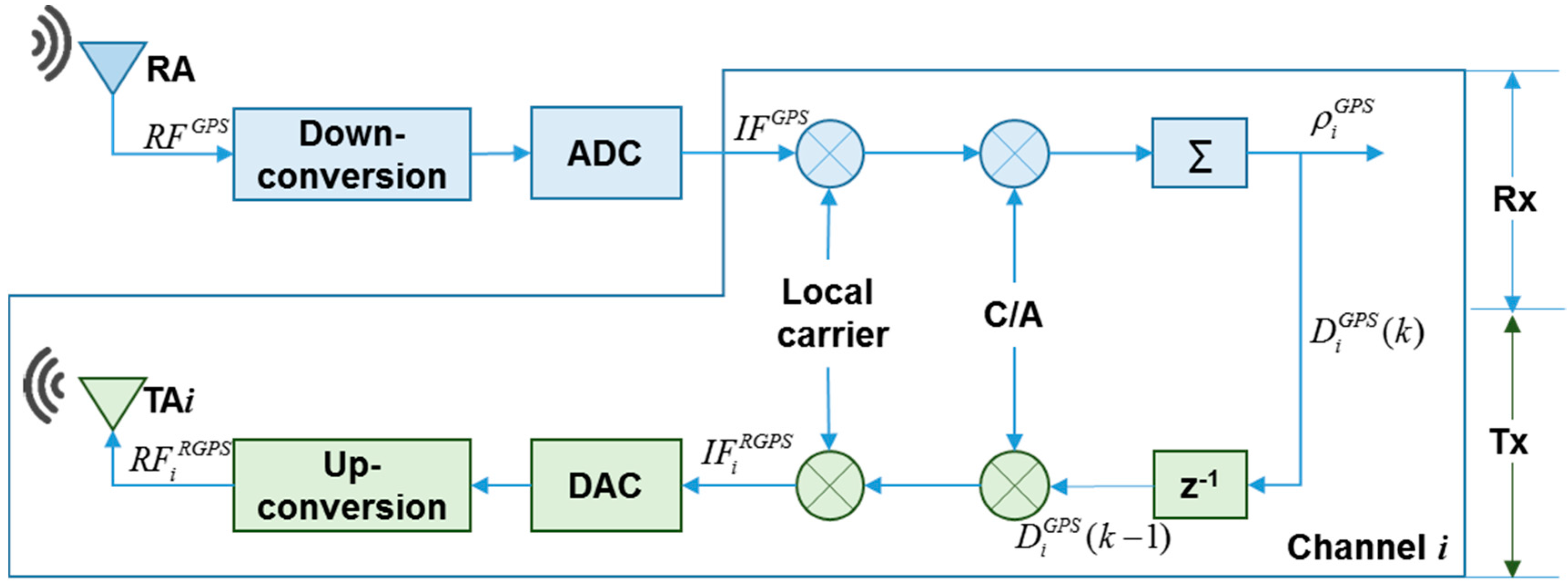
2.1. Rx/Tx

2.2. Server
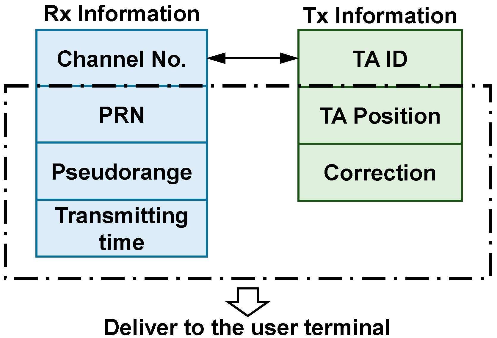
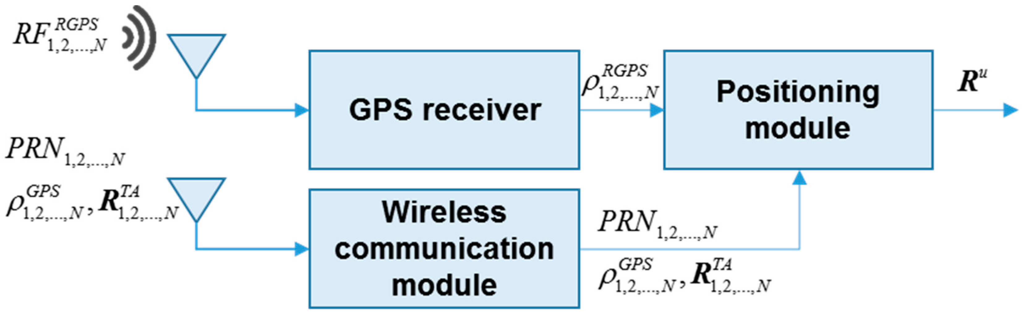
2.3. User Terminal

3. Measurement Model and Positioning Algorithm
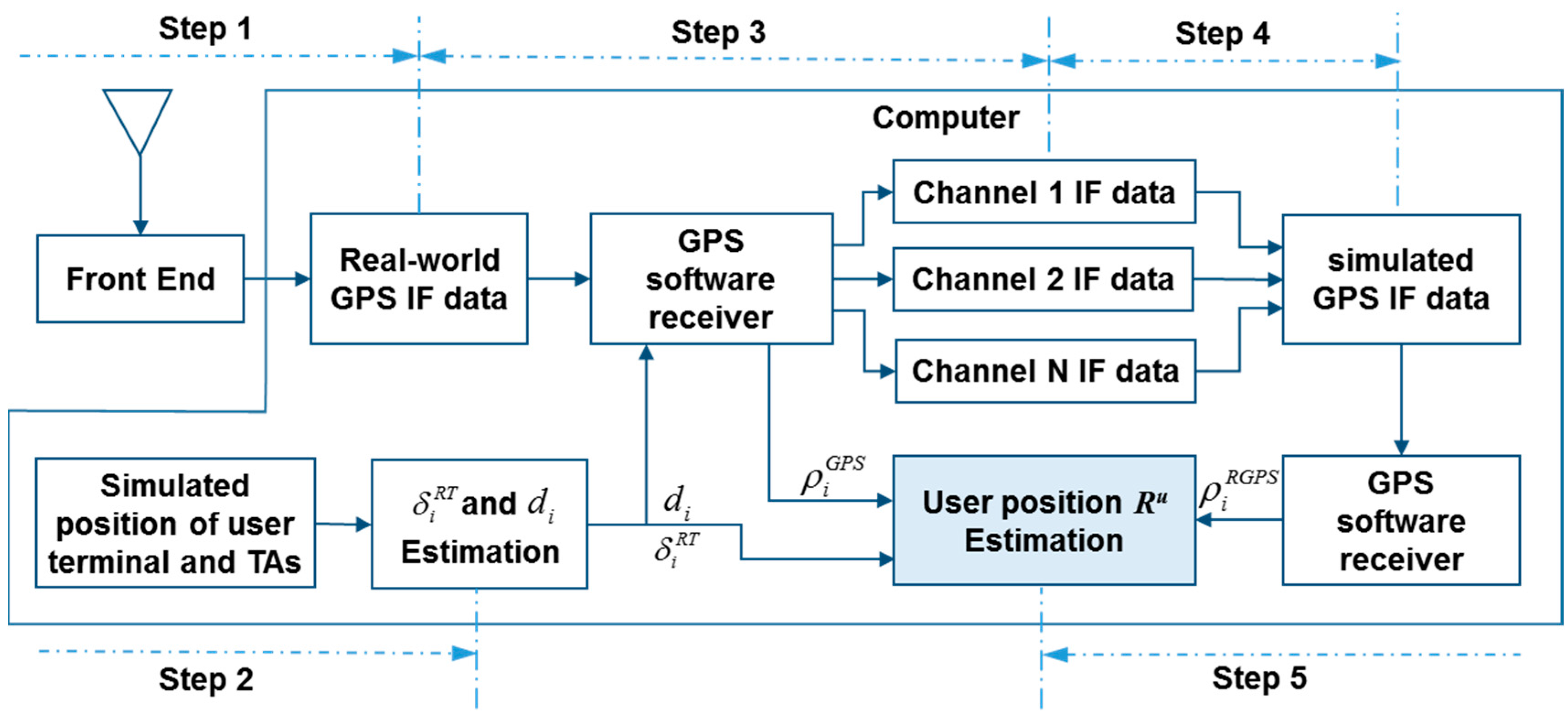
4. Simulation and Results

| GPS Signal | L1 |
|---|---|
| Sampling frequency | 16.3676 MHz |
| Intermediate frequency | 4.1043 MHz |
| Integration time | 1 ms |
| PLL bandwidth | 10 Hz |
| DLL bandwidth | 1 Hz |
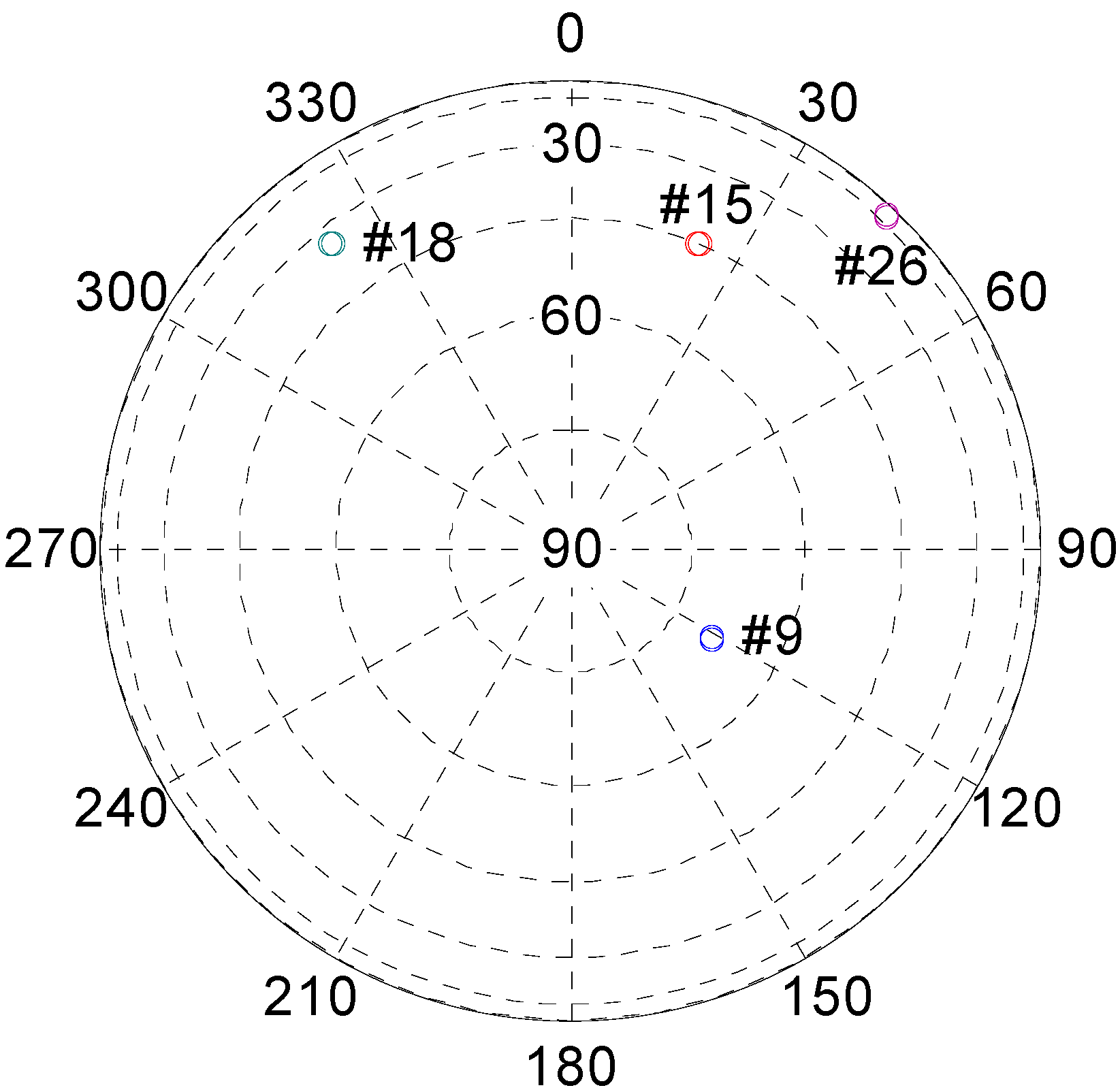
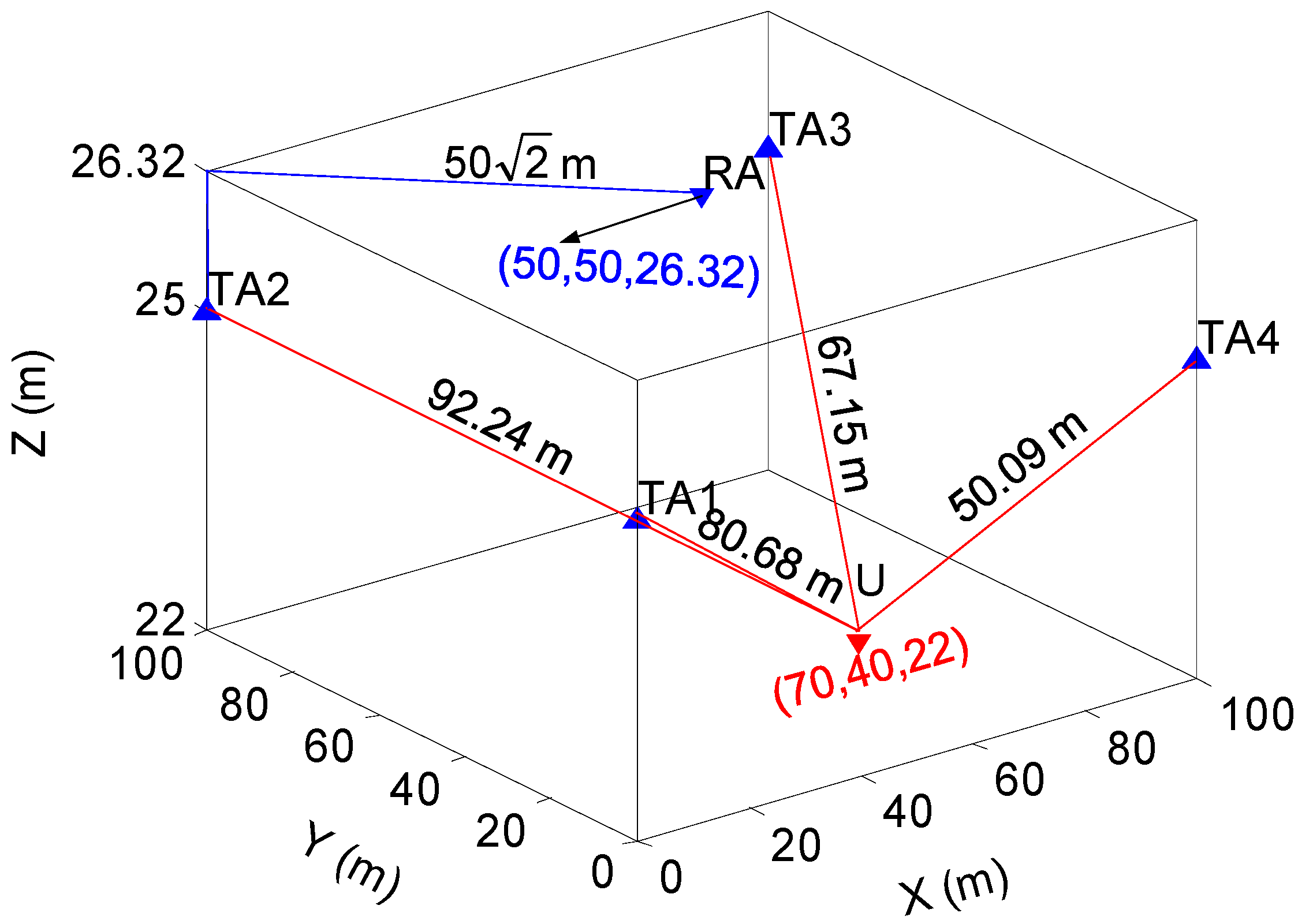
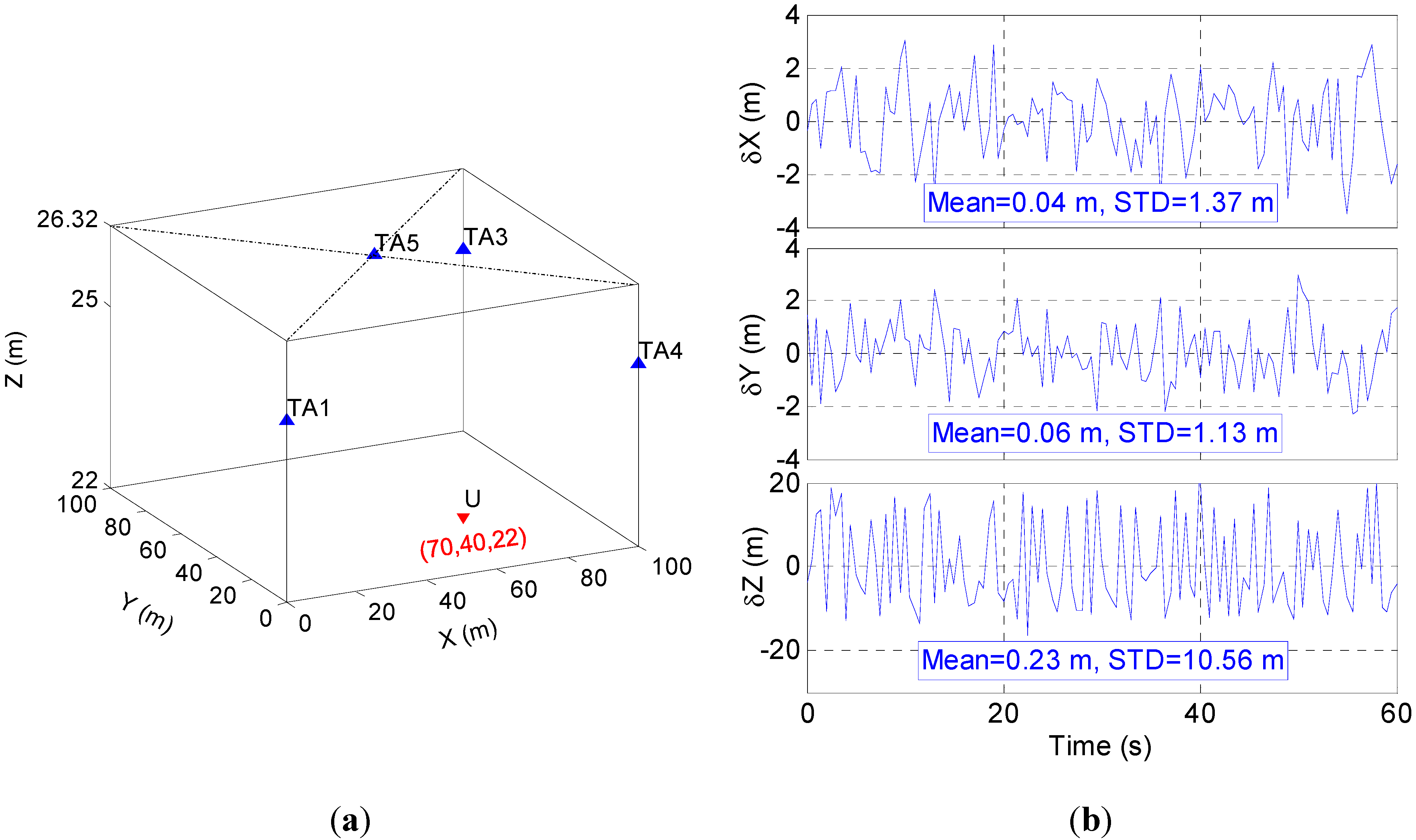
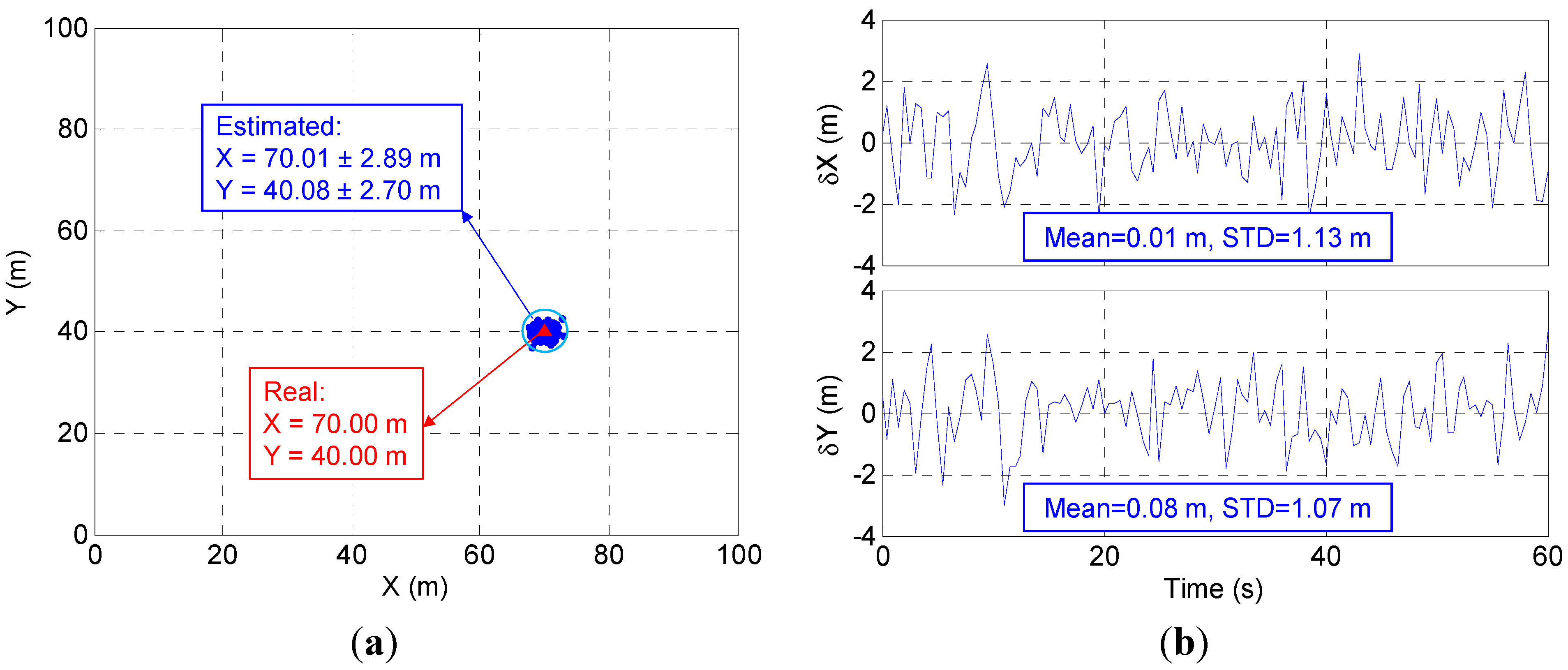
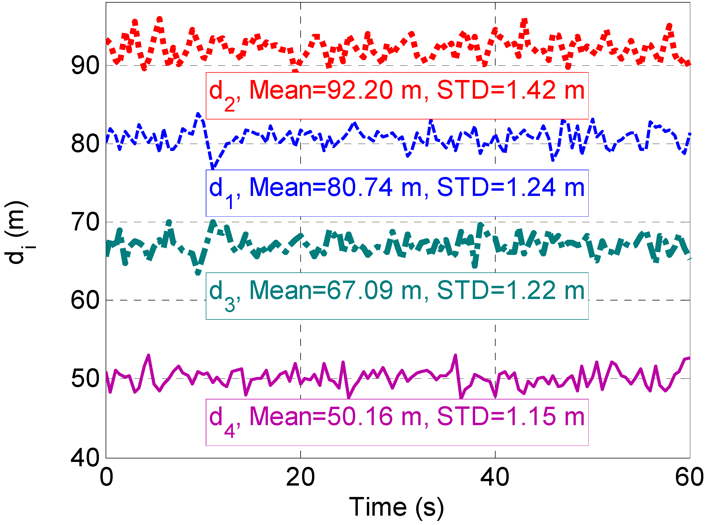
4.1. Static Simulation


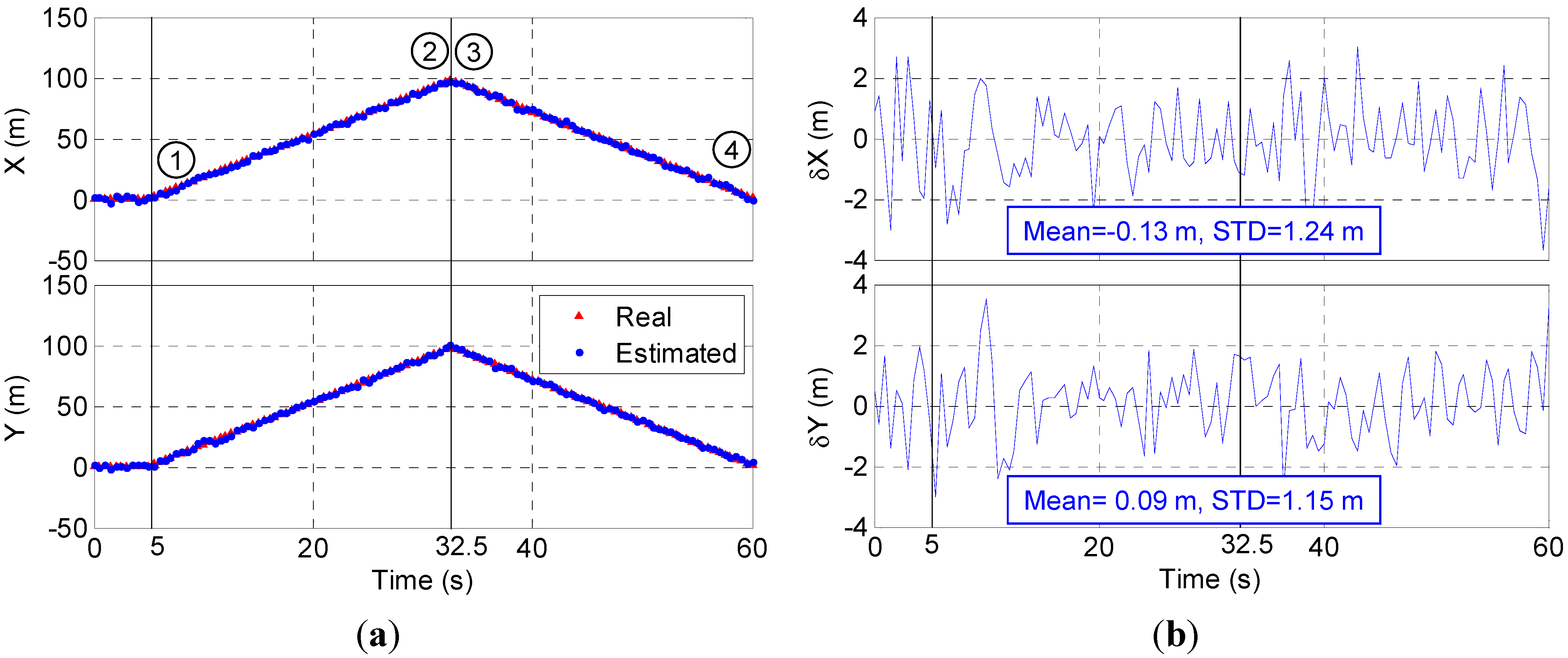
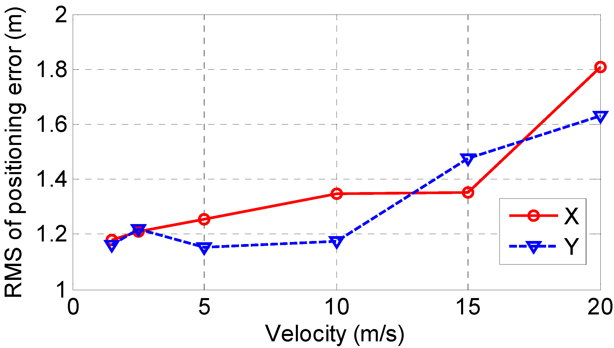
4.2. Dynamic Simulation


5. Conclusions
Acknowledgments
Author Contributions
Conflicts of Interest
References
- Mautz, R. Overview of current indoor positioning systems. Geod. Cartogr. 2009, 35, 18–22. [Google Scholar] [CrossRef]
- Medina, C.; Segura, J.C.; de la Torre, Á. Ultrasound indoor positioning system based on a low-power wireless sensor network providing sub-centimeter accuracy. Sensors 2013, 13, 3501–3526. [Google Scholar] [CrossRef]
- Ruiz, D.; Garcia, E.; Urena, J.; de Diego, D.; Gualda, D.; Garcia, J.C. Extensive ultrasonic local positioning system for navigating with mobile robots. In Proceedings of the 2013 10th Workshop on Positioning, Navigation and Communication, Dresden, Germany, 20–21 March 2013; pp. 1–6.
- Oh, J.H.; Kim, D.; Lee, B.H. An indoor localization system for mobile robots using an active infrared positioning sensor. J. Ind. Intell. Inf. 2014, 2, 35–38. [Google Scholar]
- Lee, S.; Koo, B.; Jin, M.; Park, C.; Lee, M.J.; Kim, S. Range-free indoor positioning system using smartphone with bluetooth capability. In Proceedings of the 2014 IEEE/ION Position, Location and Navigation Symposium, Monterey, CA, USA, 5–8 May 2014; pp. 657–662.
- Liu, H.-H.; Lo, W.-H.; Tseng, C.-C.; Shin, H.-Y. A wifi-based weighted screening method for indoor positioning systems. Wirel. Pers. Commun. 2014, 79, 611–627. [Google Scholar] [CrossRef]
- Liang, J.Z.; Corso, N.; Turner, E.; Zakhor, A. Image based localization in indoor environments. In Proceedings of the 2013 Fourth International Conference on Computing for Geospatial Research and Application, San Jose, CA, USA, 22–24 July 2013; pp. 70–75.
- Collin, J.; Mezentsev, O.; Lachapelle, G. Indoor positioining system using accelerometry and high accuracy heading sensors. In Proceedings of the ION GPS/GNSS 2003, Portland, OR, USA, 9–12 September 2003; pp. 1–7.
- Puengnim, A.; Patino-Studencka, L.; Thielecke, J.; Rohmer, G. Precise positioning for virtually synchronized pseudolite system. In Proceedings of the 2013 International Conference on Indoor Positioning and Indoor Navigation, Montbeliard-Belfort, France, 28–31 October 2013; pp. 1–8.
- Selmi, I.; Vervisch-Picois, A.; Gottesman, Y.; Samama, N. GNSS-based calibration of the infrastructure of the repealite indoor positioning system. In Proceedings of the 2013 International Conference on Indoor Positioning and Indoor Navigation, Montbeliard-Belfort, France, 28–31 October 2013.
- Kim, C.; So, H.; Lee, T.; Kee, C. A pseudolite-based positioning system for legacy gnss receivers. Sensors 2014, 14, 6104–6123. [Google Scholar] [CrossRef] [PubMed]
- Lazik, P.; Rowe, A. Indoor pseudo-ranging of mobile devices using ultrasonic chirps. In Proceedings of the 10th ACM Conference on Embedded Network Sensor Systems, Toronto, ON, Canada, 6–9 November 2012.
- Rizos, C.; Roberts, G.; Barnes, J.; Gambale, N. Experimental results of locata: A high accuracy indoor positioning system. In Proceedings of the 2010 International Conference on Indoor Positioning and Indoor Navigation, Zurich, Switzerland, 15–17 September 2010; pp. 1–7.
- Samama, N. Indoor positioning with gnss-like local signal transmitters. In Global Navigation Satellite Systems—Signal, Theory and Applications; Jin, S., Ed.; InTech: Rijeka, Croatia, 2012; pp. 299–338. [Google Scholar]
- Rapinski, J.; Cellmer, S.; Rzepecka, Z. Modified gps/pseudolite navigation message. J. Navig. 2012, 65, 711–716. [Google Scholar] [CrossRef]
- Rapinski, J.; Koziar, M.; Rzepecka, Z.; Cellmer, S.; Chrzanowski, A. Some considerations in designing a gps pseudolite. Artif. Satell. 2012, 47, 1–11. [Google Scholar] [CrossRef]
- Fluerasu, A.; Jardak, N.; Vervisch-Picois, A.; Samama, N. In GNSS repeater based approach for indoor positioning: Current status. In Proceedings of the European Navigation Conference, Global Navigation Satellite Systems, Naples, Italy, 3–6 May 2009.
- Vervisch-Picois, A.; Samama, N. First experimental performances of the repealite based indoor positioning system. In Proceedings of the 2012 International Symposium on Wireless Communication Systems, Paris, France, 28–31 August 2012; pp. 636–640.
- Selmi, I.; Samama, N.; Vervisch-Picois, A. A new approach for decimeter accurate GNSS indoor positioning using carrier phase measurements. In Proceedings of the 2013 International Conference on Indoor Positioning and Indoor Navigation, Montbeliard-Belfort, France, 28–31 October 2013.
- Xu, G. Theory, Algorithms and Applications; Springer-Verlag: Berlin Heidelberg, Germany, 2007. [Google Scholar]
© 2015 by the authors; licensee MDPI, Basel, Switzerland. This article is an open access article distributed under the terms and conditions of the Creative Commons Attribution license (http://creativecommons.org/licenses/by/4.0/).
Share and Cite
Xu, R.; Chen, W.; Xu, Y.; Ji, S. A New Indoor Positioning System Architecture Using GPS Signals. Sensors 2015, 15, 10074-10087. https://doi.org/10.3390/s150510074
Xu R, Chen W, Xu Y, Ji S. A New Indoor Positioning System Architecture Using GPS Signals. Sensors. 2015; 15(5):10074-10087. https://doi.org/10.3390/s150510074
Chicago/Turabian StyleXu, Rui, Wu Chen, Ying Xu, and Shengyue Ji. 2015. "A New Indoor Positioning System Architecture Using GPS Signals" Sensors 15, no. 5: 10074-10087. https://doi.org/10.3390/s150510074
APA StyleXu, R., Chen, W., Xu, Y., & Ji, S. (2015). A New Indoor Positioning System Architecture Using GPS Signals. Sensors, 15(5), 10074-10087. https://doi.org/10.3390/s150510074