Article

A Dual Sensor for pH and Hydrogen Peroxide Using Polymer-Coated Optical Fibre Tips

by
Malcolm S. Purdey
1,2,3,*,
Jeremy G. Thompson
1,2,4,
Tanya M. Monro
1,2,5,
Andrew D. Abell
1,2,3 and
Erik P. Schartner
1,2
1
ARC Centre of Excellence for Nanoscale BioPhotonics, Adelaide 5005, SA, Australia
2
Institute for Photonics and Advanced Sensing (IPAS), The University of Adelaide, North Terrace, Adelaide 5005, SA, Australia
3
Discipline of Chemistry, School of Physical Sciences, The University of Adelaide, North Terrace, Adelaide 5005, SA, Australia
4
Robinson Research Institute, School of Medicine, The University of Adelaide, North Terrace, Adelaide 5005, SA, Australia
5
University of South Australia, North Terrace, Adelaide 5001, SA, Australia
*
Author to whom correspondence should be addressed.
Sensors 2015, 15(12), 31904-31913; https://doi.org/10.3390/s151229893
Submission received: 28 October 2015 / Revised: 7 December 2015 / Accepted: 11 December 2015 / Published: 17 December 2015
(This article belongs to the Section Chemical Sensors)

Abstract

:
This paper demonstrates the first single optical fibre tip probe for concurrent detection of both hydrogen peroxide (H2O2) concentration and pH of a solution. The sensor is constructed by embedding two fluorophores: carboxyperoxyfluor-1 (CPF1) and seminaphtharhodafluor-2 (SNARF2) within a polymer matrix located on the tip of the optical fibre. The functionalised fibre probe reproducibly measures pH, and is able to accurately detect H2O2 over a biologically relevant concentration range. This sensor offers potential for non-invasive detection of pH and H2O2 in biological environments using a single optical fibre.

1. Introduction

Hydrogen peroxide (H2O2) and pH play vital combined roles in cellular signalling [1,2,3], tumour development [4,5,6,7] and reproductive health science [8,9,10,11]. For example, the unregulated production of H2O2 by an embryo is a hallmark of embryonic stress [12], while pH fluctuations during embryo culture can negatively affect embryonic development [13]. The simultaneous detection of pH and H2O2 would therefore provide significant benefit in monitoring the associated cellular processes. H2O2 and pH can be detected in cells by specific fluorophores, measuring either an increase in fluorescence intensity [14,15], or a change in emission spectra respectively [16,17]. However the use of these fluorescent probes in applications such as in vitro fertilisation (IVF) poses significant scientific and ethical questions, as their effect on the development of embryos is unknown. As such, direct contact of fluorophores with an embryo is ethically unsound and not allowable in most regulatory jurisdictions.
Optical fibre-based probes offer an attractive and non-invasive approach. Here a fluorophore of interest can be attached to the fibre surface for localised measurement without being released into the solution [18,19,20]. Various configurations of optical fibres have been examined for development of such fluorescent sensors, specifically; functionalized end-faces (tip sensors) [21,22], exposed core [23] and microstructured fibres [24,25]. Although microstructured fibre based sensors can be more sensitive than tip sensors [26], filling of the air holes with analyte is required in order to perform a measurement. This typically restricts microstructured fibres to single temporal measurements, unless microfluidics or external flushing systems are employed, and these may impede on the cell culture environment. Exposed-core fibre sensors are ideal for environmental sensing and do not require microfluidics or external flushing and offer advantages in distributed sensing. However, tip-based sensors offer potential for temporal measurements in a single location rather than distributed along the length, or can be repositioned to obtain a spatial map of the sample as desired. Tip sensors often have reduced sensitivity compared to microstructured fibres [26], especially as conventional attachment of a single layer of fluorophore to a fibre tip results in a low signal intensity [27]. However, the signal intensity can be improved by increasing the density of fluorophore on the fibre tip.
H2O2 can be detected by aryl boronate-based fluorophores such as peroxyfluor-1 (PF1) [28] and carboxyPF1 (CPF1, Figure 1) [29]. These aryl boronates have been shown as particularly effective fluorescent probes for detection of H2O2 in human spermatozoa and bovine oocytes [29,30]. pH can be detected using a range of fluorophores, with seminaphthorhodofluor-2 (SNARF2, Figure 1) offering some advantages over alternative probes, as the ratiometric emission from this probes changes its spectral features over the physiological pH range, with a pKa of 7.5 [31]. This minimises potential errors which could arise from using a solely intensity-based probe. Additionally, its emission spectrum overlaps minimally with the emission of CPF1 [32], allowing the separate interrogation of each fluorophore.
This paper reports the first dual probe for sensing pH and the detection of H2O2 by immobilising two separate fluorophores (CPF1 and SNARF-2) onto a single optical fibre tip in a polyacrylamide matrix. The two fluorophores are attached to a multi-mode fibre tip by a light-catalysed polymer coating [33], to allow for greater control of fluorophore surface density and thus subsequent signal intensity. This then allows detection of both H2O2 and pH within a single system.
Figure 1. Chemical structures of fluorescent probes used in this study. Carboxyperoxyfluor-1 (CPF1) reacts with H2O2 to form the fluorescent 6-carboxyfluorescein. Seminaphthorhodofluor-2 (SNARF2) is found in the protonated (open) form and lactone (closed) at low and high pH respectively.
Sensors 15 29893 g001

2. Experimental Section

2.1. Materials

All chemicals were purchased from Sigma-Aldrich unless otherwise stated. Bis(acrylamide) was purchased from Polysciences (Warrington, PA, USA). HPLC grade acetonitrile was purchased from Scharlau. 100 mM Phosphate buffer solutions were prepared from monosodium phosphate and disodium phosphate in Milli-Q water. Multimode fibre (200 µm core diameter, FG200UCC) was purchased from Thorlabs (Newton, NJ, USA), with one end connectorised for attachment to the optical setup.

2.2. Polyacrylamide Photo-Polymerisation on Optical Fibre Tips

A solution of 3-(trimethoxysilyl)propyl methacrylate (5 μL) in 10% acetic acid solution (30 μL) and ethanol (1 mL) was mixed and sonicated until clear. Multi-mode fibre was cleaved and each segment immersed in the methacrylate solution for 1 h. The fibre tip was then dried under N2, rinsed with Milli-Q water and re-dried under N2. The distal end of the fibre was coupled into a 405 nm source (Crystalaser 405 nm) using a 10× microscope objective. A monomeric stock solution comprising of 3% bisacrylamide, 27% acrylamide and 70% pH 6.5 phosphate buffer solution was dissolved under sonication. CPF1-NHS (0.2 mg), and SNARF2-NHS (0.2 mg) were added to this solution (400 µL) and 200 µL of the resulting solution was pipetted into a small Eppendorf tube. Triethylamine (10 µL/mL) was added to the mixture, and the fibre tip was immersed in this solution exactly 60 s after addition of the triethylamine and immediately irradiated under 405 nm light for 10 s at 13.4 mW, to form a polymeric coating on the fibre tip.

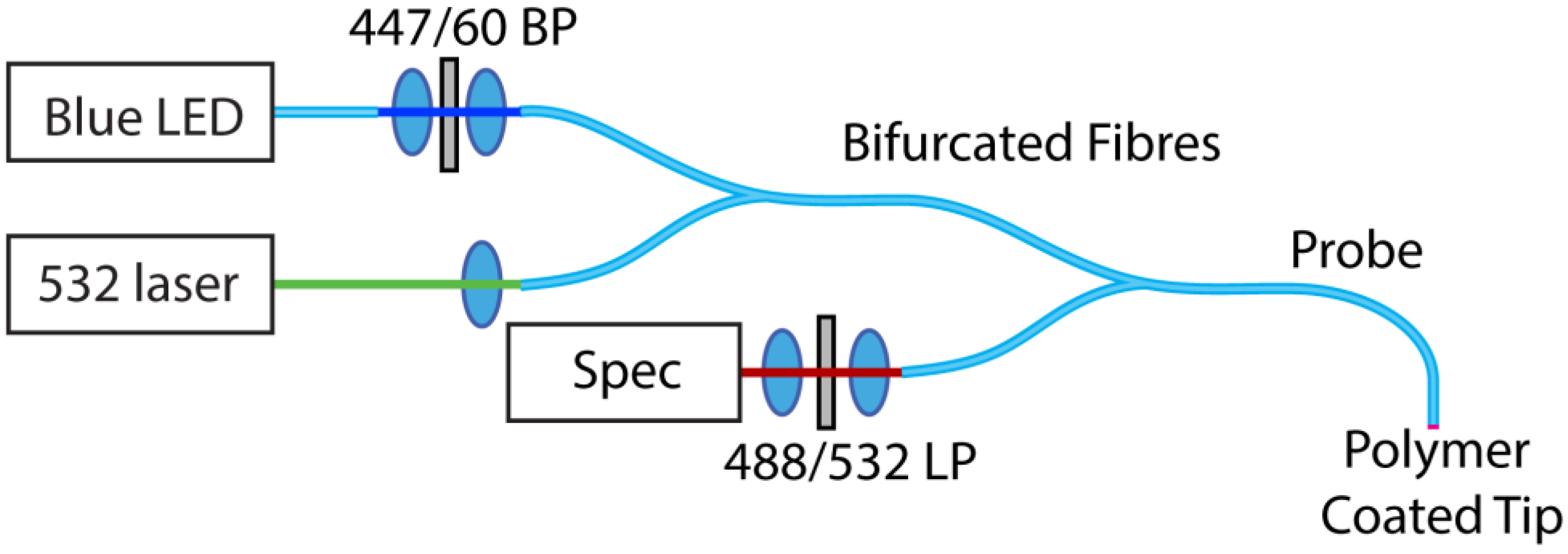
2.3. Optical Measurements

The experimental configuration used for optical measurements is shown in Figure 2 below.
Figure 2. Experimental configuration for optical measurements of the combined pH/peroxide sensor. The blue LED source was used to illuminate the peroxide sensitive carboxyperoxyfluor-1 (CPF1) fluorophore, while the green excites the pH sensitive seminaphtharhodafluor-2 (SNARF).
Sensors 15 29893 g002
A 470 nm blue LED source (Thorlabs M470F1, Newton, NJ, USA) with an appropriate bandpass filter (Semrock Brightline 447/60, Rochester, NY, USA) was coupled into one input of a bifurcated fibre (Ocean Optics 200 µm, UV/VIS). Attached CPF1 was then excited with light from a 532 nm green laser (Crystalaser 25 mW, Reno, NV, USA) coupled into the other input for excitation of the SNARF. An additional bifurcated fibre was used to connect the excitation sources to the sensing fibre, with the remaining input connected to the input of the spectrometer (Horiba iHR550, Synapse detector, Kyoto, Japan). Long-pass filters were inserted directly into the spectrometer input cage, with 488 nm (Semrock 488 nm Edgebasic) and 532 nm (Semrock 532 nm Razoredge) used for peroxide and pH respectively.
The two excitation channels were controlled independently, with only one excitation wavelength used at any particular time to excite either the peroxide or pH channel. The corresponding emission filter was used with each excitation source to attenuate residual pump light from the fibres. The use of connectorised fibres and multi-mode fibres greatly simplifies the measurement procedure, as no adjustments or realignment are required when swapping between pH and peroxide measurements.

3. Results and Discussion

3.1. Hydrogen Peroxide Detection

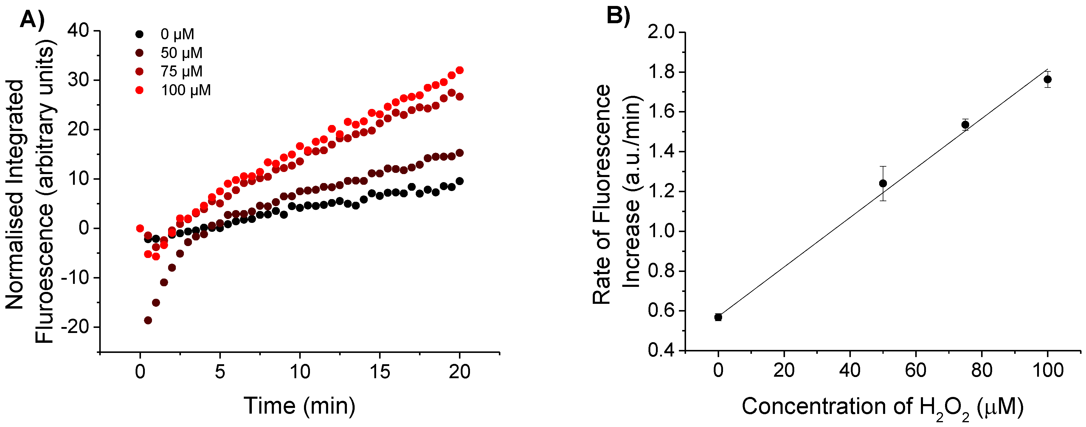
3.1.1. Detection of Biologically Relevant H2O2 Concentrations

CPF1 and SNARF2 immobilised on fibre tips were tested in solutions containing H2O2 to establish the sensitivity of this surface configuration. Fibre tips were first functionalised with 3-(trimethoxysilyl)propyl methacrylate, then dipped into a solution of acrylamide/bisacrylamide with N-hydroxysuccinimide esters of CPF1 and SNARF2. The N-succinimide esters of CPF1 and SNARF2 increase solubility in the acrylamide solution to provide a more reproducible density of fluorophores embedded in the polymer matrix. Excitation light (405 nm) was coupled into the distal end of the fibre and the tip irradiated for 10 s to form a polymer layer on the tip containing the fluorophores. The functionalised fibres were dipped into a range of concentrations of H2O2 (0, 50, 75 and 100 μM) in pH 7.5 phosphate buffer, and the emission peaks from CPF1 at 520 nm and SNARF at 600 and 660 nm were observed under 473 nm excitation. A low excitation power was used (27 μW) for these trials to minimise any potential effects of photobleaching. The entire spectrum was then integrated and normalised to the initial peak of CPF1 at 520 nm. This was necessary because each probe has slightly different initial fluorescence values and hence raw intensity values cannot be directly compared. Furthermore, each fibre probe was only used once for detection of H2O2 to ensure maximum consistency between trials. Figure 3 shows an increase in normalised integrated fluorescence due to CPF1 over a 20 min exposure to H2O2. This time interval was dictated by the reaction rate of aryl boronates such as CPF1 with H2O2 [34].
Normalised fluorescence of CPF1 in the presence of 100 μM H2O2 is greater than for the control, which lacked H2O2 (Figure 3A). This increase in fluorescence is consistent with CPF1 reacting with H2O2 on the fibre tip. Furthermore, a plot of the rate of increase in fluorescence vs concentration of H2O2 (Figure 3B) clearly shows this rate increasing as the concentration of H2O2 increases from 0 μM to 50 μM, 75 μM and 100 μM of H2O2. A similar increase was observed in our previous studies on the detection of H2O2 with CPF1 in solution [27], and we have also shown that CPF1 is able to detect relevant H2O2 concentrations in reproductive biology [29]. Hence, this probe exhibits sufficient sensitivity for this biological environment.
An initial drop in fluorescence was observed for some probes (see Figure 3A), particularly the probe immersed in a 50 μM H2O2 solution. This is likely due to a change in emission properties of the fluorophores as the probe is moved from air into the solution. A more rapid increase in fluorescence was observed in the first 5 min, suggesting the probe is equilibrating in the new medium. After 5 min the probes show a near linear increase in fluorescence intensity. Thus, an incubation time of greater than 5 min is required to give an accurate indication of the rate of increase in fluorescence due to H2O2. A plateau was not observed over the time course of the experiment, suggesting quantitative data should be obtained from the rate of increase in fluorescence rather than the overall increase in fluorescence.
It is also important to note that an increase in the integrated fluorescent signal was evident, even in the absence of H2O2 (Figure 3A). A decrease in fluorescence would be expected if photobleaching or leaching of the fluorophore from the polymer occurred over the course of the experiment. The effect of photobleaching on CPF1 was of particular interest, since CPF1 is oxidised by H2O2 to give 5-carboxyfluorescein. 5-carboxyfluorescein is known to photobleach [35], a process which occurs more rapidly in the presence of reactive oxygen species such as H2O2 [36]. In order to accurately sense H2O2 with CPF1, low rates of photobleaching must be achieved. An increase in fluorescence in the absence of H2O2 suggests that photobleaching was not occurring on the fibre during the experiment. This is an important observation for the practical use of the probe since the fibre’s ability to sense accurately would be reduced by photobleaching of the fluorophores on the fibre tip.
Figure 3. (A) Integrated fluorescence intensity from CPF1 using blue excitation with varied peroxide concentration in pH 7.5 buffer; 100 μM H2O2 shows an increased fluorescent response from the fibre without H2O2; (B) Slope of integrated fluorescence for increasing concentrations of H2O2 (0, 50, 75 and 100 μM). Error bars indicate the standard error of the calculated slope.
Sensors 15 29893 g003

3.1.2. Effect of Change in pH on Detection of H2O2

The effect of pH on the detection of H2O2 in fibre was next investigated by immersing functionalised fibre tips in solutions of H2O2 of differing pH. Fibre tips were functionalised with CPF1 and SNARF2 as before and separately immersed in 100 μM separate solutions of H2O2 at a pH of 7.05, 7.55 or 8.05. A 470 nm light source was coupled into the fibre for excitation and the increase in fluorescence was recorded over 20 min. All spectra were integrated and normalised as before, with the results shown in Figure 4A. The rate of increase in fluorescence was calculated as depicted in Figure 4B. The observed rate at pH 8.05 was 1.5 times greater than the rate observed at pH 7.05 (Figure 4B).
The reaction rate of aryl boronates (such as CPF1) with H2O2 is higher in more basic solutions [37]. CPF1 reacts with the conjugate base of H2O2 (hydroperoxide ion HOO) [15] to give fluorescent 5-carboxyfluorescein. As the pH increases, more H2O2 dissociates into its conjugate base, HOO. The concentration of HOO available to react with CPF1 will therefore be higher in more basic solutions, accounting for the observed upward trend in rates due to increasing pH (Figure 4B). Furthermore, the product of CPF1 with H2O2 is a carboxyfluorescein, and fluorescein exhibits different quantum yields of fluorescence at differing pH [38]. Thus, the pH of the solution is highly pertinent to the accurate detection of H2O2. This is further highlighted by a comparison of rates of increase in fluorescence at different pH and H2O2 concentration, shown in Figure 3B and Figure 4B. A rate of approximately 1.2 a.u./min was calculated for a 100 μM solution of H2O2 in pH 7.05 (Figure 4B). However, a similar rate was calculated for a 50 μM solution of H2O2 at a pH of 7.55 (Figure 3B). The observed rate in these experiments is clearly dependent on the pH, in addition to the concentration of H2O2. It is hence necessary that the pH of a solution must be known in order to calculate an unknown concentration of H2O2 resulting from an increase in fluorescence. Therefore, it is critical that the probe also incorporates a pH sensitive component to accurately determine the H2O2 concentration. This improves upon many systems for detection of H2O2 that do not simultaneously measure pH, despite the reported effect on H2O2 detection [15].
Figure 4. Response of CPF1 to 100 μM H2O2 in solutions that varied in pH. (A) Integrated fluorescent responses of probes to 100 μM H2O2 in pH 7.05, 7.55 and 8.05 over 20 min using blue excitation; (B) Rate of increase in fluorescence of each probe with H2O2 in each of the 3 pH solutions. Error bars indicate the standard error of the calculated slope.
Sensors 15 29893 g004

3.2. pH Sensing

3.2.1. Initial pH Sensing

The sensitivity of these functionalised fibre tips was defined across a series of solutions of differing pH, ranging from 6.5 to 8.5. Fibres functionalised with CPF1 and SNARF2 as before were dipped into phosphate buffer solutions of each pH. 532 nm light attenuated to 13 μW was coupled into the fibre for excitation, and the fluorescent signal from immobilised SNARF2 was collected after 1 min equilibration time. The fibre was removed from solution, dried, and immersed in a subsequent buffer solution. Two fibre probes were calibrated in this way using sixteen buffer solutions ranging from pH 6.5 to 8.5 as shown in Figure 5. This broad pH range (6.4–8.5) was chosen in order to demonstrate the potential of the probe in biological applications beyond the narrower constraints of an embryo. Five additional probes were then calibrated in selected solutions across this range (see fibres 3–7 in Figure 5B). The fluorescence spectra were recorded as shown in Figure 5A. The probe exhibits a decrease in intensity of fluorescence at 600 nm as the pH increases, with an increase in intensity at 660 nm.
Figure 5. pH response of SNARF-2 embedded in polyacrylamide on fibre tip to varied pH. (A) Emission spectra of SNARF in various pH buffers; (B) Ratio of emission peak intensities 600/660nm shown with over multiple trials. The effect of noise was reduced by taking the mean of eight values between 598–602 nm and 558–662 nm. Error bars represent the standard deviation of these values.
Sensors 15 29893 g005
The pH of the buffer was correlated with the observed fluorescent signal by calculating the ratio of intensities at 600 nm and 660 nm for each spectrum (Figure 5B). This analysis revealed an inverse correlation between this fluorescent ratio and pH of the solution. The plot also shows a linear trend over the pH range 7.0 to 8.0 and indicates that the sensor should be of use for determining the pH of a biological sample near physiological pH. Moreover, multiple fibre trials produced similar pH calibration curves (Figure 5B) showing good reproducibility between fibres. This data also indicates that SNARF2 bound to a fibre tip behaves as in solution [32]. Therefore, SNARF2 effectively senses the pH of a buffer solution when embedded in polyacrylamide on a fibre tip.

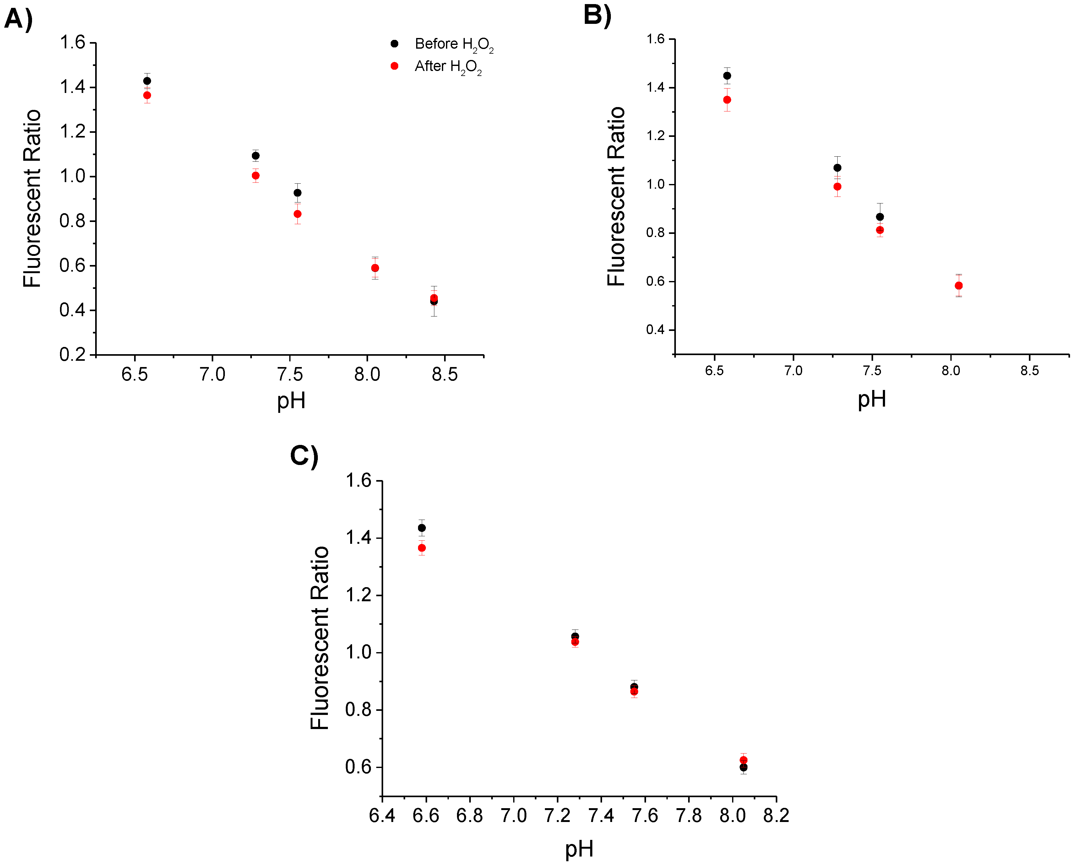
3.2.2. pH Sensing before and after Detection of Hydrogen Peroxide

The functionalised fibre probes were used to sense pH before and after immersion in H2O2, in order to determine if this affected the pH sensing capability. Each fibre was functionalised with CPF1 and SNARF2 and calibrated in phosphate buffer solutions of known pH as described in Section 3.2.1. The fibre tips were then immersed for 20 min in one of three H2O2 solutions: 100 μM solution of H2O2 in pH 7.55 buffer, 50 μM H2O2 in pH 7.55 buffer or 100 μM H2O2 in pH 7.05 buffer. These conditions represent the range of conditions that the probe may experience in unknown samples. Each probe was calibrated again in phosphate buffer solutions as above. The resulting pH calibration curves were plotted for each probe both before and after immersion in H2O2 (Figure 6).
Figure 6. Sensing of pH before and after immersion in H2O2. Each graph plots the ratio of emission peaks of SNARF2 at 600/660 nm with the pH of the buffer solution tested, before and after solutions: (A) 100 μM solution of H2O2 in pH 7.55 buffer; (B) 50 μM H2O2 in pH 7.55 buffer; (C) 100 μM H2O2 in pH 7.05 buffer. Three different samples were trialled before and after H2O2 solutions to demonstrate the independence of the result to concentration of H2O2 or the pH of the H2O2 solution. To reduce any effect of noise, the mean of eight values between 598–602 nm and 558–662 nm is given. Error bars represent the standard deviation of these values.
Sensors 15 29893 g006
The fluorescent ratios shown in Figure 6A show minimal changes before and after immersion in 100 μM H2O2 in pH 7.55. This indicates that reaction of H2O2 with CPF1 does not affect the sensing of pH by SNARF2. Figure 6B reveals similar fluorescent ratios before and after immersion in 50 μM H2O2 in pH 7.55 buffer. H2O2 again does not affect the sensing of pH over the tested concentration range, 50 μM to 100 μM H2O2. Figure 6C shows the fluorescent ratios of SNARF on fibre tips before and after immersing in 100 μM H2O2 in pH 7.05 buffer. As per the previous results, the fluorescent ratio curves did not change significantly after immersion in H2O2. Importantly, immersing the probe into a solution containing H2O2 does not affect the pH sensing capability of the probe. This demonstrates that SNARF2 can be used on optical fibre tips for sensing pH independent of the detection of H2O2 by CPF1.

4. Conclusions/Outlook

The tip of an optical fibre has been functionalised with two separate fluorophores, CPF1 and SNARF2 embedded in polyacrylamide, in order to allow measurement of the H2O2 concentration and pH respectively. The probe is demonstrated to effectively detect H2O2 over a physiological pH range. The probe shows a minimum detectable concentration of 50 μM H2O2 at pH 7.5, and pH was measured repeatedly over the range 6.5–8.5 with resolution of 0.1 pH units. Each fluorophore was used in tandem by alternating excitation sources, i.e., blue excitation to interrogate CPF1 for H2O2 detection, and green excitation for SNARF2 to sense pH, with minimal cross-talk. The combination of pH and H2O2 detection also addressed the crucial issue of accurate measurement of H2O2 in solutions with varying or unknown pH, where the pH of the solution alters the apparent H2O2 concentration. This is the first example of a dual pH and H2O2 probe and is an important proof of concept for the detection of pH and H2O2 in ethically complex biological environments such as found in an IVF laboratory.
This probe could find potential application if placed near the cumulus cells of an oocyte for monitoring of extracellular pH and H2O2 fluxes during fertilisation and during early embryonic development. Tapering of the fibre tip could also increase the resolution from 200 μm to a few microns if required [39]. This fibre probe may offer potential not only in embryology, but a range of biological applications whereby the system must remain isolated from any external agents such as organic fluorophores.

Supplementary Files

Supplementary File 1

Acknowledgments

This research was supported in part by Cook Medical Pty Ltd and Australian Research Council linkage grant LP 110200736 and the ARC Centre of Excellence for Nanoscale BioPhotonics (CNBP). This work was performed in part at the OptoFab node of the Australian National Fabrication Facility (ANFF) utilising Commonwealth and SA State Government funding. T.M. acknowledges the support of an ARC Georgina Sweet Laureate Fellowship FL130100044.

Author Contributions

M.S.P., E.P.S., T.M.M. and A.D.A. conceived and designed the experiments; J.G.T. provided biological specifications for the probe; M.S.P. performed the experiments and analysed the data; E.P.S. and A.D.A. assisted with analysis; M.S.P wrote the paper with contributions from E.P.S., A.D.A, J.G.T. and T.M.M.

Conflicts of Interest

The authors declare no conflict of interest.

References

  1. Gough, D.R.; Cotter, T.G. Hydrogen peroxide: A Jekyll and Hyde signalling molecule. Cell Death Dis. 2011, 2. [Google Scholar] [CrossRef] [PubMed]
  2. Neill, S.J.; Desikan, R.; Clarke, A.; Hurst, R.D.; Hancock, J.T. Hydrogen peroxide and nitric oxide as signalling molecules in plants. J. Exp. Bot. 2002, 53, 1237–1247. [Google Scholar] [CrossRef] [PubMed]
  3. Thannickal, V.J.; Fanburg, B.L. Reactive oxygen species in cell signaling. Am. J. Physiol. Lung Cell. Mol. Physiol. 2000, 279, L1005–L1028. [Google Scholar]
  4. Szatrowski, T.P.; Nathan, C.F. Production of large amounts of hydrogen peroxide by human tumor cells. Cancer Res. 1991, 51, 794–798. [Google Scholar] [PubMed]
  5. Burdon, R.H. Superoxide and hydrogen peroxide in relation to mammalian cell proliferation. Free Radic Biol. Med. 1995, 18, 775–794. [Google Scholar] [CrossRef]
  6. Gerweck, L.E.; Seetharaman, K. Cellular pH gradient in tumor versus normal tissue: potential exploitation for the treatment of cancer. Cancer Res. 1996, 56, 1194–1198. [Google Scholar] [PubMed]
  7. Engin, K.; Leeper, D.B.; Cater, J.R.; Thistlethwaite, A.J.; Tupchong, L.; McFarlane, J.D. Extracellular pH distribution in human tumours. Int. J. Hyperth. 1995, 11, 211–216. [Google Scholar] [CrossRef] [PubMed]
  8. Bize, I.; Santander, G.; Cabello, P.; Driscoll, D.; Sharpe, C. Hydrogen peroxide is involved in hamster sperm capacitation in vitro. Biol. Reprod. 1991, 44, 398–403. [Google Scholar] [CrossRef] [PubMed]
  9. Nasr-Esfahani, M.H.; Aitken, J.R.; Johnson, M.H. Hydrogen peroxide levels in mouse oocytes and early cleavage stage embryos developed in vitro or in vivo. Development 1990, 109, 501–507. [Google Scholar] [PubMed]
  10. Armstrong, J.S.; Rajasekaran, M.; Chamulitrat, W.; Gatti, P.; Hellstrom, W.J.; Sikka, S.C. Characterization of reactive oxygen species induced effects on human spermatozoa movement and energy metabolism. Free Radic. Biol. Med. 1999, 26, 869–880. [Google Scholar] [CrossRef]
  11. Baumber, J.; Ball, B.A.; Gravance, C.G.; Medina, V.; Davies-Morel, M.C.G. The Effect of Reactive Oxygen Species on Equine Sperm Motility, Viability, Acrosomal Integrity, Mitochondrial Membrane Potential, and Membrane Lipid Peroxidation. J. Androl. 2000, 21, 895–902. [Google Scholar] [PubMed]
  12. Morado, S.; Cetica, P.; Beconi, M.; Thompson, J.G.; Dalvit, G. Reactive oxygen species production and redox state in parthenogenetic and sperm-mediated bovine oocyte activation. Reproduction 2013, 145, 471–478. [Google Scholar] [CrossRef] [PubMed]
  13. Ocon, O.M.; Hansen, P.J. Disruption of Bovine Oocytes and Preimplantation Embryos by Urea and Acidic pH. J. Dairy Sci. 2003, 86, 1194–1200. [Google Scholar] [CrossRef]
  14. Chan, J.; Dodani, S.C.; Chang, C.J. Reaction-based small-molecule fluorescent probes for chemoselective bioimaging. Nat. Chem. 2012, 4, 973–984. [Google Scholar] [CrossRef] [PubMed]
  15. Lippert, A.R.; Van de Bittner, G.C.; Chang, C.J. Boronate Oxidation as a Bioorthogonal Reaction Approach for Studying the Chemistry of Hydrogen Peroxide in Living Systems. Acc. Chem. Res. 2011, 44, 793–804. [Google Scholar] [CrossRef] [PubMed]
  16. Lin, J. Recent development and applications of optical and fiber-optic pH sensors. TrAC Trends Anal. Chem. 2000, 19, 541–552. [Google Scholar] [CrossRef]
  17. Han, J.; Burgess, K. Fluorescent Indicators for Intracellular pH. Chem. Rev. 2009, 110, 2709–2728. [Google Scholar] [CrossRef] [PubMed]
  18. Heng, S.; Nguyen, M.-C.; Kostecki, R.; Monro, T.M.; Abell, A.D. Nanoliter-scale, regenerable ion sensor: Sensing with a surface functionalized microstructured optical fibre. RSC Adv. 2013, 3, 8308–8317. [Google Scholar] [CrossRef]
  19. Foo, H.T.C.; Ebendorff-Heidepriem, H.; Sumby, C.J.; Monro, T.M. Towards microstructured optical fibre sensors: surface analysis of silanised lead silicate glass. J. Mater. Chem. C 2013, 1, 6782–6789. [Google Scholar] [CrossRef]
  20. Heng, S.; Mak, A.M.; Stubing, D.B.; Monro, T.M.; Abell, A.D. Dual Sensor for Cd(II) and Ca(II): Selective Nanoliter-Scale Sensing of Metal Ions. Anal. Chem. 2014, 86, 3268–3272. [Google Scholar] [CrossRef] [PubMed]
  21. Tan, W.; Shi, Z.Y.; Smith, S.; Birnbaum, D.; Kopelman, R. Submicrometer intracellular chemical optical fiber sensors. Science 1992, 258, 778–781. [Google Scholar] [CrossRef] [PubMed]
  22. Schartner, E.; Monro, T. Fibre Tip Sensors for Localised Temperature Sensing Based on Rare Earth-Doped Glass Coatings. Sensors 2014, 14, 21693–21701. [Google Scholar] [CrossRef] [PubMed]
  23. Palmisano, T.; Prudenzano, F.; Warren-Smith, S.C.; Monro, T.M. Design of exposed-core fiber for methadone monitoring in biological fluids. J. Non Cryst. Solids 2011, 357, 2000–2004. [Google Scholar] [CrossRef]
  24. Smolka, S.; Barth, M.; Benson, O. Highly efficient fluorescence sensing with hollow core photonic crystal fibers. Opt. Express 2007, 15, 12783–12791. [Google Scholar] [CrossRef] [PubMed]
  25. Wolfbeis, O.S. Fiber-optic chemical sensors and biosensors. Anal. Chem. 2008, 80, 4269–4283. [Google Scholar] [CrossRef] [PubMed]
  26. Schartner, E.P.; Tsiminis, G.T.; Henderson, M.R.; Monro, T.M. A Comparison Between Multimode Tip and Suspended Core Fluorescence Optical Fibre Sensors; Optical Society of America: Munich, Germany, 2015. [Google Scholar]
  27. Purdey, M.S.; Schartner, E.P.; Sutton-McDowall, M.L.; Ritter, L.J.; Thompson, J.G.; Monro, T.M.; Abell, A.D. Localised hydrogen peroxide sensing for reproductive health. Proc. SPIE 2015, 9506. [Google Scholar] [CrossRef]
  28. Chang, M.C.Y.; Pralle, A.; Isacoff, E.Y.; Chang, C.J. A selective, cell-permeable optical probe for hydrogen peroxide in living cells. J. Am.Chem. Soc. 2004, 126, 15392–15393. [Google Scholar] [CrossRef] [PubMed]
  29. Purdey, M.S.; Connaughton, H.S.; Whiting, S.; Schartner, E.P.; Monro, T.M.; Thompson, J.G.; Aitken, R.J.; Abell, A.D. Boronate probes for the detection of hydrogen peroxide release from human spermatozoa. Free Radic. Biol. Med. 2015, 81, 69–76. [Google Scholar] [CrossRef] [PubMed]
  30. Sutton-McDowall, M.L.; Purdey, M.; Brown, H.M.; Abell, A.D.; Mottershead, D.G.; Cetica, P.D.; Dalvit, G.C.; Goldys, E.M.; Gilchrist, R.B.; Gardner, D.K.; et al. Redox and anti-oxidant state within cattle oocytes following in vitro maturation with bone morphogenetic protein 15 and follicle stimulating hormone. Mol. Reprod. Dev. 2015, 82, 281–294. [Google Scholar] [CrossRef] [PubMed]
  31. Whitaker, J.E.; Haugland, R.P.; Prendergast, F.G. Spectral and photophysical studies of benzo[c]xanthene dyes: Dual emission pH sensors. Anal. Biochem. 1991, 194, 330–344. [Google Scholar] [CrossRef]
  32. Srikun, D.; Albers, A.E.; Chang, C.J. A dendrimer-based platform for simultaneous dual fluorescence imaging of hydrogen peroxide and pH gradients produced in living cells. Chem. Sci. 2011, 2, 1156–1165. [Google Scholar] [CrossRef]
  33. Song, A.; Parus, S.; Kopelman, R. High-Performance Fiber-Optic pH Microsensors for Practical Physiological Measurements Using a Dual-Emission Sensitive Dye. Anal. Chem. 1997, 69, 863–867. [Google Scholar] [CrossRef] [PubMed]
  34. Sikora, A.; Zielonka, J.; Lopez, M.; Joseph, J.; Kalyanaraman, B. Direct oxidation of boronates by peroxynitrite: Mechanism and implications in fluorescence imaging of peroxynitrite. Free Radic. Biol. Med. 2009, 47, 1401–1407. [Google Scholar] [CrossRef] [PubMed]
  35. Song, L.; Hennink, E.J.; Young, I.T.; Tanke, H.J. Photobleaching kinetics of fluorescein in quantitative fluorescence microscopy. Biophys. J. 1995, 68, 2588–2600. [Google Scholar] [CrossRef]
  36. Platkov, M.; Tirosh, R.; Kaufman, M.; Zurgil, N.; Deutsch, M. Photobleaching of fluorescein as a probe for oxidative stress in single cells. J. Photochem. Photobiol. B Biol. 2014, 140, 306–314. [Google Scholar] [CrossRef] [PubMed]
  37. Xu, J.; Li, Q.; Yue, Y.; Guo, Y.; Shao, S. A water-soluble BODIPY derivative as a highly selective “Turn-On” fluorescent sensor for H2O2 sensing in vivo. Biosens. Bioelectron. 2014, 56, 58–63. [Google Scholar] [CrossRef] [PubMed]
  38. Martin, M.M.; Lindqvist, L. The pH dependence of fluorescein fluorescence. J. Lumin. 1975, 10, 381–390. [Google Scholar] [CrossRef]
  39. Leung, A.; Shankar, P.M.; Mutharasan, R. A review of fiber-optic biosensors. Sens. Actuators B Chem. 2007, 125, 688–703. [Google Scholar] [CrossRef]

