Review

Power Approaches for Implantable Medical Devices

1
LACIME Laboratory, University of Quebec, ÉTS, 1100 Notre-Dame West, Montreal, QC H3C 1K3, Canada
2
Division of Engineering, STEM, University of Washington, Bothell, WA 98011, USA
*
Author to whom correspondence should be addressed.
Sensors 2015, 15(11), 28889-28914; https://doi.org/10.3390/s151128889
Submission received: 30 August 2015 / Revised: 15 October 2015 / Accepted: 6 November 2015 / Published: 13 November 2015
(This article belongs to the Special Issue Power Schemes for Biosensors and Biomedical Devices)

Abstract

:
Implantable medical devices have been implemented to provide treatment and to assess in vivo physiological information in humans as well as animal models for medical diagnosis and prognosis, therapeutic applications and biological science studies. The advances of micro/nanotechnology dovetailed with novel biomaterials have further enhanced biocompatibility, sensitivity, longevity and reliability in newly-emerged low-cost and compact devices. Close-loop systems with both sensing and treatment functions have also been developed to provide point-of-care and personalized medicine. Nevertheless, one of the remaining challenges is whether power can be supplied sufficiently and continuously for the operation of the entire system. This issue is becoming more and more critical to the increasing need of power for wireless communication in implanted devices towards the future healthcare infrastructure, namely mobile health (m-Health). In this review paper, methodologies to transfer and harvest energy in implantable medical devices are introduced and discussed to highlight the uses and significances of various potential power sources.

1. Introduction

In the past few decades, we have witnessed tremendous development in electronics, micro- and nano-fabrication, and wireless technology which have greatly enhanced the quality and efficacy of healthcare as well as life-science research [1,2,3,4]. These innovations dovetailed with advanced biomaterials have enabled miniaturized sensors and biocompatible devices that could be implanted in vivo in humans and animal models, allowing diagnosis, prognosis and biological investigations [5,6,7]. Chronic diseases of inner organs have been elucidated in animal models, and/or diagnosed and treated in real patients with support from numerous implantable devices [6,8,9,10,11]. Recently, flexible and stretchable electronics has been introduced and demonstrated, showing promise for the future of healthcare, biological-science discoveries and medicine [2,7,12]. Unreachable locations in vertebrates’ bodies challenging scientists such as the deep brain, intravascular regions, inside the heart or even a location inside a single cell have been assessed and investigated with miniaturized implantable systems [13,14,15,16].
Implantable Medical Devices (IMDs) to improve healthcare, aiding or delivering the functions of certain malfunctioning organs have been around for years. They have been utilized for diagnosis, prognosis and treatment. IMDs can be categorized as active and passive devices depending on whether they require a power source or not, respectively. Nowadays, a host of chronic diseases have been addressed using IMDs all over the body, from the brain, cochlea and retina to the heart, lungs, knee joints and even vessels, the esophagus and the bladder. According to statistics from a decade ago, there were about three million people around the world with pacemakers and each year 600,000 more pacemakers were being implanted. Besides, more than 60,000 people were treated with cochlear implants [17]. The numbers have been rapidly increasing in recent years due to the larger population and a better healthcare system. For example, more than 230,000 new pacemakers were implanted in the USA in 2009 [18]. These facts indicate that IMDs have become more and more popular in humans’ life.
To ensure proper operation, most IMDs need to rely on a permanent and sufficient power supply, thus numerous power sources for IMD have been widely investigated in the last decades. Different power approaches can allow for the autonomous operation of IMDs by generating electrical power to replace or supplement existing battery power. The existing major challenges have been size limitations, inaccessibility, the need to work continuously and biocompatibility.
Since the first medical implant, the pacemaker, was introduced in 1972 using batteries [19,20,21,22,23], various types of batteries have been developed and deployed for IMDs [24,25,26,27,28,29,30,31,32,33]. Among those, lithium-based (Li) batteries have been the most popular power source owing to their high volumetric energy density as well as comparatively compact sizes [28,34,35]. Further, they have a considerably durable longevity of 5 to 10 years, and thus are appropriate for long-term applications [36]. Besides, bio-fuel cells exploiting biocatalysts for generating electric power from renewable biodegradable materials such as glucose or amylum are also potential sources [30,35]. Enzyme-based biofuel cells are able to operate under mild conditions (20–40 °C and close to pH = 7.0) generating milliwatt level power. Making them suitable for the majority of IMDs such as pacemakers, cardiac defibrillators and drug delivery systems. One other type—nuclear batteries—which was also introduced in early 1970s, were utilized to extend the lifespan of IMDs for more than 10 years. Their operation is based on the carried energy emitted by the particles from radioisotopes [37]. However, they were discontinued in the 1980s due to the potential risks and the conclusion from physicians that IMDs should be updated with new technologies at least once a decade [38].
Alternative solutions have been also proposed, investigated and developed, by which energy was generated and harvested from potential sources surrounding the implants. The aforementioned biofuel cells are great candidates since they can exploit glucose and oxygen which are abundant in the blood to generate energy [27,39,40,41]. Further, vertebrates’ bodies and their daily activities are great sources of energy through heating (body heat) and movements like breathing and motion, that could be exploited to power up IMDs replacing the traditional batteries. For instance, the maximum temperature difference between the inner parts and the skin is 8 °C, which is sufficient to generate a few hundred microwatts of electricity using thermoelectric generators [42,43,44]. On the other hand, piezoelectric generators have been employed to convert kinetic energy into electricity utilizing piezoelectric materials [45,46,47]. Although they are able to generate considerably higher power, on the order of milliwatts, piezoelectric generators usually require massive motion, and hence are not appropriate for most implant locations [48,49,50]. Electrostatic and electromagnetic mechanisms have been also used to harvest energy using body motions, however their size limitations and low generated power limits their use in practical in vivo applications [51,52,53,54].
Instead of exploiting potential sources generated by the host, energy could be supplied to IMDs by an external unit to either charge the battery or continuously power the batteryless implant. This may be accomplished optically, ultrasonically or electromagnetically. Optical-charging methods consist of a photovoltaic cell in the IMD which receives power from a laser diode usually operating in the near-infrared or infrared range [55]. Ultrasonic devices have attracted growing interest in recent years due to their comparative efficiency, compactness and immunity to electromagnetic radiation [56,57,58,59,60]. Nonetheless, inductive power transmission across the body tissue is currently the only viable solution to deliver sufficient power to various kinds of IMDs with miniaturized dimensions [61]. This method is based on a pair of antennas by which power could be transferred through a mutual inductive coupling link. Therefore, antenna design and orientation, working distance and frequency, as well as the designated power would be considered. The power ranges of all the methods and IMDs are summarized in Figure 1.
Figure 1. Power ranges of methods and IMDs. The scale is not in the right ratio, it is only for a conceptual illustration. Batteries and charging methods can deliver high power; however, in practical scenarios, it depends on the location of IMD, the size of IMD as well as the tissue.
Sensors 15 28889 g001
In this review paper, we introduce methods to power active IMDs and present insightful discussions about each method. Approaches are categorized into two main groups: (1) IMDs that work independently with or without a one-time battery, or sustainably; and (2) IMDs which could be either battery-based or batteryless, obtaining power transferred from an external unit. Figure 2 presents these two groups. An overview about ultimate goals of IMDs is presented in the Discussion section followed by in-depth discussions of the most popular method, namely inductive coupling.
Figure 2. Approaches to power IMDs.
Sensors 15 28889 g002

2. Methods to Power IMDs

2.1. Independent Systems

The first battery was invented by Volta in 1796 and since then numerous types have been discovered and applied to diverse uses in human life [62]. In general, batteries store energy in the forms of chemical substances which can produce electricity. Batteries contain anodes, cathodes and electrolytes to allow ions to move thus forming currents. There are three categories of power capabilities used for battery performance (low rate, medium rate and high rate). Although the definition is not yet clear, low-rate batteries should be able to provide a constant current of 100 µA while high-rate ones can supply a pulse power of at least 5 W for 10 s. Thus, the gap could be filled with medium-rate batteries. Among IMDs, pacemakers use low currents, neuro-stimulators and drug pumps need medium-rate ones and implantable defibrillators/cardioverters (ICDs) require extremely high power as well as additional longevity [32].

2.1.1. Lithium Batteries

Typically, Li batteries were developed and appeared in the forms of Li metal anodes with cathode systems including iodine (Li/I2) [2,6,24,63,64], manganese oxide (Li/MnO2) [7,12,65,66], carbon mono fluoride (Li/CFx) [67,68,69,70], silver vanadium oxide (Li/SVO) [71,72,73] or hybrid cathodes (Li/CFx-SVO) [29,32,64,74,75]. As reliable sources for long-term applications such as cochlear implants, pacemakers, cardiac defibrillators or drug delivery, these Li batteries have been widely employed to provide appropriate power levels ranging from microamperes to amperes, as demanded by different types of IMDs [26,29,32].
Among those, Li/I2 batteries have been proved to be safer and more reliable than others for uses with implantable pacemakers, thus they have been utilized by most manufacturers during the last 40 years [27]. Li/I2 batteries have a discharge voltage of up to 3.6 V, which is equal to three times the voltage generated by Ni-based cells. Their energy density can reach 210 W·h/kg, which can power a cardiac pacemaker for several years. Further, it is usually easier to measure the remaining energy of Li/I2 batteries than other Li-based batteries, thus providing enough time to change the battery for IMDs [27]. On the other hand, Li/SVO batteries have been employed majorly for ICDs in the last 30 years owing to their high capacity of over 300 W·h/kg. The presence of metallic silver also drastically improves the electronic conductivity [76]. In the mid-range, the systems with cathodes of thionyl-chloride (Li/SOCl2) have been widely used for neuro-stimulators and drug pumps.
The recent advances in material research have led to a new class of Li-based batteries, namely flexible Li or Li polymer batteries [77,78]. While its advantages in flexible electronics and wearable consuming devices are undoubted, further implementations for implants have been limited due to the remaining obstacles in size and questions related to potential toxicity.

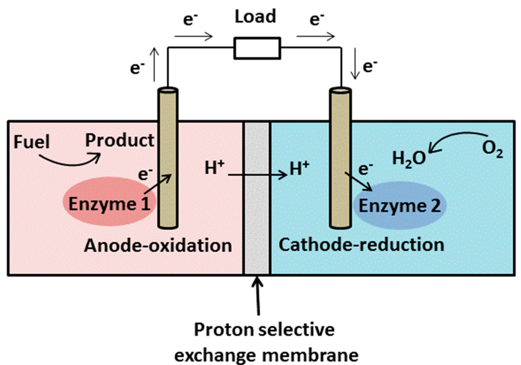
2.1.2. Bio-Fuel Cells

In general, bio-fuel cells are devices that transform biochemical energy into electricity based on electrochemical reactions involving biochemical pathways [30]. The link between biology and electricity was first discovered by Galvani in his experiments with frogs’ legs in 1791. He found the muscles of dead frogs’ legs twitched when electrical sparks were applied. The concept of ‘fuel cell’ was demonstrated in 1839 when Grove fully reversed the electrolysis process of water. He was able to recombine oxygen and hydrogen to produce water and interestingly, an electrical current [79]. The development of microbial-fuel cells (MFC) was then pioneered by Potter in 1911 when he discovered that one could generate a current of 0.2–0.5 mA at 0.3–0.5 V when a platinum electrode was placed into cultures of E. coli [80]. This indicated the potential of using microorganisms to generate power. The demonstration was achieved in 1931 when Cohen implemented biofuel cells providing 2 mA of current and 35 V voltage [30,81]. In a fuel cell, there are oxidation and reduction reactions occurring at the anode and cathode, respectively. Electrons released by the oxidation travel to the cathode to form an electrical current via an external circuit [30]. At the same time, protons move to the cathode through a proton-selective exchange membrane (Figure 3) [27].
Figure 3. Schematic of a bio-fuel cell.
Sensors 15 28889 g003
Based on the catalyst used, bio-fuel cells can be classified into microbial fuel (MFC) or enzymatic bio-fuel (EBC) cells; whereas considering the pathway through which electrons move from anode to cathode, we can distinguish between direct or non-direct cells [27,30]. For example, the fuel can come from glucose and oxygen in the blood following these reactions:
At anode: C6H12O6 → C6H10O6 + 2H+ + 2e
At cathode: O2 + 4H+ + 4e → 2H2O
The interest in MFCs was triggered in 1960s owing to the USA space program during which possible powering technologies had been sought for a waste disposal system for space flights [30]. The application of MFCs for IMDs was first initiated in 1960s when cell-free enzyme-based fuel cells were used for implantable artificial hearts [30,82]. During the 1970s, EBCs using glucose as fuel and oxygen as oxidizer were investigated to provide power for IMDs [27,30] and since then, various approaches and modifications have been proposed to enhance the performance as well as to target specific applications [28]. In 2003, Mano and colleagues reported a miniaturized bio-fuel cell capable of operation while implanted in a grape. They were able to produce a power of 2.4 μW at 0.52 V which was very promising for the applications with compact implants [83].
Bio-fuel cells present several advantages including the use of existing recyclable materials in Nature, the moderate operating conditions for the reactions and the biocompatibility between bio-fuel cells and the human body [31]. Nevertheless, challenges still remain. Firstly, it is difficult to maintain the biocatalyst over a long period and surgical intervention is of course not a desired option. Secondly, the microwatt level of bio-fuel cells limits their use in a wide range of applications. Finally, even though they are highly biocompatible, unavoidable biofouling still occurs that can damage the device or harm the patients [27].

2.1.3. Nuclear Batteries

In nuclear batteries, power is transformed to electricity through energy carried by particles emitted from radioisotopes. This process could be achieved in several ways. For instance, some utilize the electric potential difference produced by the particle emitted from the radioisotopes, some use the electric potential coming from the ionization of emitted particle bundles, others employ the photoelectrical conversion prompted by a fluorescent material, and the rest exploit the heat energy of radiation. The advantages of nuclear batteries lie in the fact that they can provide much longer service life (>15 years) than all other competitors, and their output energy is extremely stable, regardless of environmental factors (temperature, pressure and electric field). For example, the Betacel produced by Medtronics, Inc. (Minneapolis, MN, USA) with a volume of 1.8 mL, a height of 1.02 cm and a diameter of 1.52 cm, can provide 50 μW of power [27]. Further, their safety has been proved for as long as they are kept hermetic, however, the potential radioactivity danger as well as their expensive cost make them still unacceptable [32,33].

2.1.4. Thermoelectricity

The thermoelectric effect could be exploited to obtain electrical energy using the temperature differences in the human body. Naturally, our body presents temperature differences between locations thus forming temperature gradients. When a temperature gradient is applied in a thermoelectric module, a potential difference appears across the material through the Seebeck effect (Figure 4a) [84]. Since the human body is an unlimited heat-energy source, these generators’ lifetime is also naturally unlimited [85,86,87,88]. Nevertheless, the thermal gradients in the human body are relatively small, making it difficult to achieve significant power outputs. Since thermoelectric generators are a type of heat engine, their efficiency is proportional to the Carnot efficiency which is defined as [89]:
ŋ c = 1 T c T h =   T h   T c T h
where ŋc is the Carnot efficiency, Th and Tc represent the hot and cold temperatures in Kelvin, respectively. TEGs are normally made up of semiconductor materials, with the most common ones being bismuth telluride (Bi2Te3) and polycrystalline silicon-germanium (poly-SiGe) film [90]. A thermoelectric module is usually formed by n-doped and p-doped semiconductor thermocouples placed electrically in series and thermally in parallel. In 1999, Stark and Stordeur reported a 0.19 cm3 thermoelectric generator which could produce 1.5 µW and 5.8 µW at 5 K and 10 K of temperature gradient, respectively [91]. The device was fabricated by sputtering the thermoelectrically effective material Bi2Te3 on 75 µm thick Kapton (Dupont, Wilmington, DE, USA) substrates to obtain the thermopile structure. The final integration density was 11.9 thermocouples/mm3. Later in 2004s, Strasser et al. introduced their work in which micro-machined CMOS thermoelectric generators were developed using poly-SiGe material deposited on a polysilicon substrate. They obtained a power output of 1 µW with generators of 1 cm2 in size with respect to 5K in temperature gradient [92]. In fact, the maximum temperature difference between the inner part of the body and the skin surface is about 8 K, therefore, the maximum output power can be about 180 μW/cm2 [93]. Thus it can be seen that thermoelectric generators only provide sufficient power for IMDs which require low microwatt power. To increase the output power, a large number of thermocouples needs to be cascaded in a proper way but this would face the issues of size, reliability and biocompatibility [84].
Figure 4. Conceptual views of (a) thermoelectricity; and (b) piezoelectricity.
Sensors 15 28889 g004

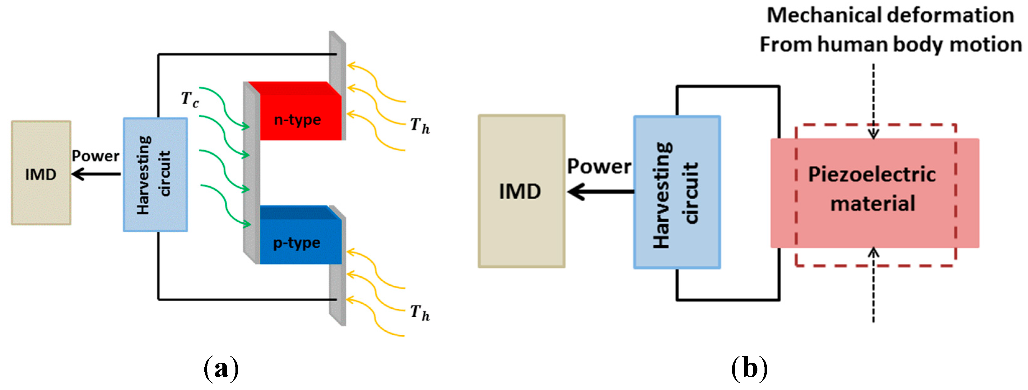
2.1.5. Piezoelectricity

The piezoelectric phenomenon was discovered in 1880 by the French physicists Jacques and Pierre Curie [94]. It could be verified that certain materials generate a proportional electrical polarization with respect to the applied mechanical stress via the piezoelectric effect. To date, numerous piezoelectric materials have been utilized to generate energy for various applications [95,96]. The physical phenomenon underlying here is based on the fact that the electrical charge accumulating in certain solid materials will be induced when it is subject to mechanical deformation (Figure 4b). Therefore, piezoelectric transducers could exploit the mechanical energy produced by our body motions [45,46,47]. The human body motions can be classified into two categories: continuous motions such as human respiration and blood flow, and discontinuous motions such as walking and hand movement. Several groups have investigated the use of discontinuous human body motion for piezoelectric energy harvesting [97,98,99]. The piezoelectric transducer is integrated in moving locations such as joints, whole-body center mass motion, muscle twitches and into shoes [98,100,101,102,103]. The ankle, knee, hip, elbow, and shoulder motions can generate up to 69.8 W, 49.5 W, 39.2 W, 2.1 W, and 2.2 W, respectively [98]. On the other hand, the continuous motions obtained from blood flow or respiration can provide lower power compared with that of the piezoelectric power harvester using discontinuous motion. For example, the maximum power generated by a piezoelectric plate with a radius of 5.62 mm and a thickness of 28 μm in a blood-flow environment is 0.33 μW [104]. Obviously, piezoelectric harvesters are good candidates to power implants, but they need significant movements to generate considerable power, thus the practical implantable locations are limited (i.e., knee, elbow, foot). For instance, efforts by Kymissis et al. in 1998 resulted in a 1 W of output power delivered by a piezoelectric transducer integrated in a shoe heel [46]. However, achieving and harvesting energy from such a system in vivo remain the most important questions to answer. Again, the small size and the biocompatibility issues are always the biggest challenges.

2.1.6. Electrostatic Generators

Electrostatic generators produce electricity via electrostatic induction which is based on the electrostatic potential energy as the result of conservative Coulomb forces [105]. They are designed to exploit mechanical motion to induce electrical energy as the moving parts of the transducer are under effect of an electric field. A common construction for electrostatic generators consists of two conductive plates that are electrically isolated via air, vacuum or a dielectric insulator (capacitor), and relatively mobile (Figure 5a) [53]. The distance between the two electrodes of the capacitor changes due to the movement or to the vibration of one movable electrode caused by the motion of human body.
Figure 5. Conceptual views of (a) electrostatic; and (b) electromagnetic generators.
Sensors 15 28889 g005
There are two operation modes for an electrostatic energy harvester: constant charge mode and constant voltage mode [106]. The plates are charged via an external source such as a battery. Besides, there are three different types of electrostatic generators which can be defined according to their actuation direction: the in-plane gap closing, out-of-plane closing and in-plane overlap [107]. The in-plane gap closing techniques offer the highest output power compared to other actuation techniques. Electrostatic generator harvesting systems can be built by silicon micromachining fabrication techniques and present good integration capabilities with microelectronic circuits and other technologies, thus standing out as good candidates for IMDs. Microelectromechanical systems-based (MEMS-based) technologies enable miniaturized size, making these generators implantable inside the human body [52,108]. Recently, several works on the use electrostatic power harvesting systems to power biomedical devices have been reported. For example, an electrostatic generator was reported to exploit ventricular motion and heartbeat to feed a cardiac pacemaker and could generate 36 μW and 58 μW, respectively [54,109]. Further, Meninger et al. developed an electrostatic generation system which could produce 8 µW of power using MEMS-based technology. In their work, Miao and colleagues implemented a non-resonant MEMS-based electrostatic generator, which could thus provide flexibility of operation with a wide range of excitation frequencies. They obtained 80 µW for operation at 30 Hz with respect to movement of 0.1 m/s [108]. Overall, the high output impedance and voltage of the electrostatic generators making them less suitable for power supply devices due to the reduced amounts of available current due to the high output voltage. In addition, the amount of energy produced is typically low and these generators usually need an additional voltage source to initially charge the capacitor, representing the major disadvantage of this technology.

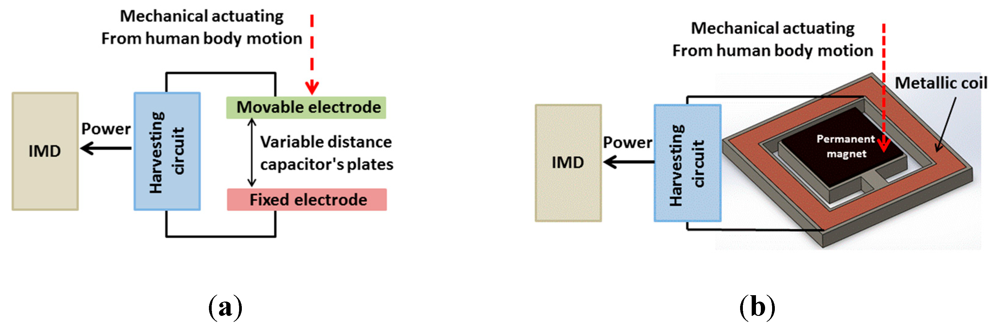
2.1.7. Electromagnetic Generators

Electromagnetic generators harvest energy based on the Faraday–Neumann–Lenz law which states that the relative motion between a coil and a permanent magnet produces a time-variable magnetic flux and consequently generates a voltage. This can be done in two ways: (1) relative motion is utilized while the generating system is fixed; and (2) rigid body motion is used with the inertia force of a weight on the generator [110]. Typically, the power is produced through the relative movement of the magnet and coil, or due to the changes in the magnetic field [51,111]. Therefore, the amount of electricity generated can be a function of magnetic field strength, relative motion velocity and the number of turns of the coil. Like those approaches based on piezoelectric or electrostatic transducers, electromagnetic generators exploit human body motions to generate power (Figure 5b).
The low-frequency and irregular movements of humans make electromagnetic techniques suitable for powering IMDs. For example, with the repeating contraction of the heart muscle at a frequency between 0.5 and 2 Hz, a power of 40–200 μW could be generated [112,113]. Roberts et al. investigated an electromagnetic generator using MEMS technology to enhance the power for pacemaker batteries in clinical trials [114]. The abdomen moves with a frequency of 0.3 Hz during breathing, producing a power of about 1.1 mW through an electromagnetic generator with a volume of 16 cm3 [115]. Using human walking, an electromagnetic generator with a size of 2.6 mm2 could generate 400 μW [116]. High performance bulk magnets, multi-turn and macroscale coils are readily available; nevertheless, the main challenge of the MEMS fabrication technology utilized in this approach is the poor properties of planar magnets [51]. In addition, the electromagnetic generators produce lower power compared with that obtained by piezoelectric generators.

2.2. Systems with an External Unit

While independent systems can provide solutions which bring comfort and avoid complexity, they showing their weaknesses in the areas of reliability, low output power (MFCs, thermoelectricity) as well as potential to cause toxicity and failing to deliver biocompatibility. Systems with external units to transfer energy continuously are therefore of interest with the increasing need of communication between IMDs and smart devices. The power can be sent through the body tissues optically, mechanically or electromagnetically, and these methods are presented and discussed in the following sections.

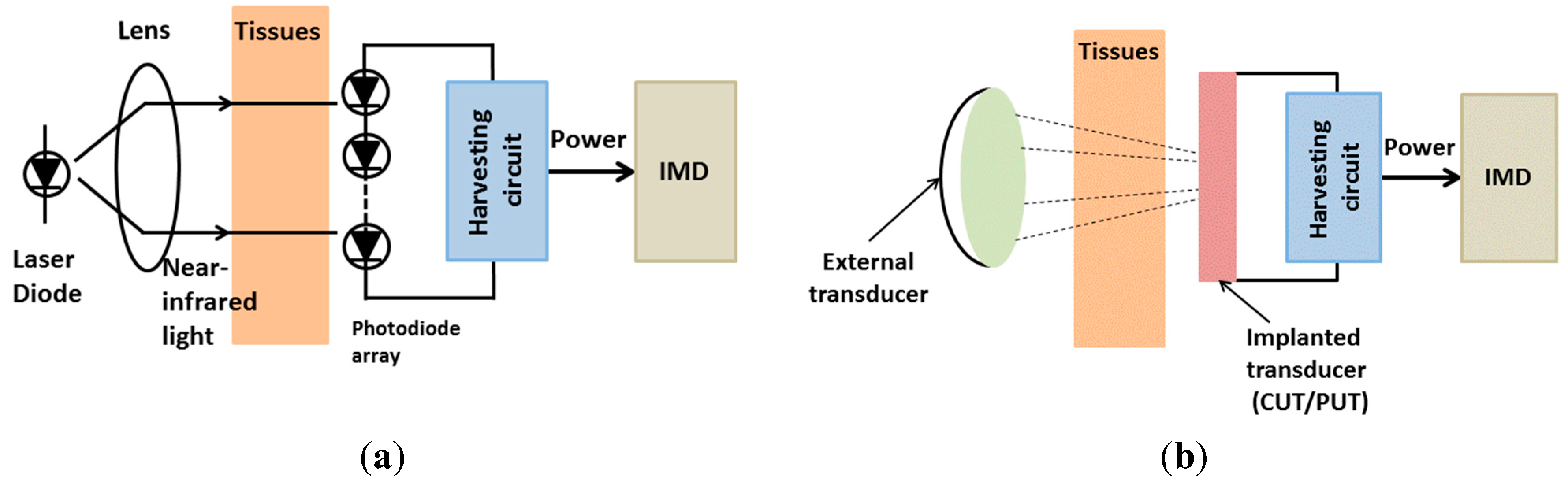
2.2.1. Optical Charging

Optical charging methods utilize a photovoltaic cell integrated in the implant. The power can be transmitted through a laser diode in the near-infrared (near-IR) or infrared region and received by an array consisting of photovoltaic cells [55,117]. Light typically has low interactivity with biological tissues. Depending on the wavelength, the radiation allows to access deep inside biological tissues. The photovoltaic-cell array converts the received radiation into a current to charge/operate the IMDs (Figure 6a).
Figure 6. Conceptual views of: (a) optical charging method; and (b) ultrasonic transducer.
Sensors 15 28889 g006
The photovoltaic cell is composed of a p-n junction of a large-band-gap semiconductor. The junction is optically charged as incident photons form electron-hole pairs, enabling electron mobility. If a load is connected, free electrons will flow through the load and then go back to the cell, where the holes are located [118]. These devices can generate power on the order of hundreds of microwatts. The photovoltaic cell array with surface area of 2.1 cm2 charged by a power density of 22 mW/cm for 17 min can generate a 20 μA current, which is sufficient for a pacemaker to operate for 24 h [119]. Using this approach, not only power, but information data can also be transferred using the optical link [120]. Nevertheless, during the charging period, the laser irradiation could raise the skin temperature by 1.4 °C, which may cause side effects [121]. In addition, this method remains several drawbacks, such as large size and low efficiency.

2.2.2. Ultrasonic Transducer

This technology has received growing interest in the past years [56,57,58,59] due to its advantages compared with other technologies in efficiency, size and immunity to electromagnetic radiation from other devices [60]. The ultrasonic transducer is excited mechanically by an external ultrasound source using an ultrasonic transducer which can operate through capacitance mode or piezoelectric mode [122,123]. The implanted ultrasonic generator produces power from a received acoustic wave transmitted by an external unit. The incident acoustic wave is converted to electrical voltage through the capacitance change or the piezoelectric effect in cases of capacitive ultrasonic transducer (CUT) or piezoelectric ultrasonic transducer (PUT), respectively (Figure 6b). An ultrasonic power harvesting system can be fabricated using MEMS technology, therefore, the compactness makes them suitable for IMDs. However, the high voltage requirement makes CUTs unsuitable for in vivo operations. On the other hand, PUTs are promising as they utilize piezoelectric materials to convert the received acoustic waves into power. In 1988, Cochran et al. reported the first implanted ultrasonic power source which operated with an input voltage of 10–20 V at a frequency of 2.25 MHz of the external ultrasound source to excite a 5 × 5 × 0.9 mm3 piezo-ceramic transducer. The device could generate an output power of 1.5 mW/cm2 [124]. Besides transferring power, a ultrasonic system can be used to send data to an IMD [125]. Further, a piezo-ceramic transducer with a diameter of 3.5 mm implanted inside living tissues and excited by an external circular transmitter (12 mm diameter) at a frequency of 2.25 MHz was able to generate an output power up to 1.5 m·W/cm2 capable of driving a peripheral nerve micro-stimulator [126]. In general, the major advantage of this approach is the ease of choosing the operating wavelength. The long-wavelength ultrasounds can penetrate deeper into the human body but cover an undesirable area, contrariwise the short-wavelength waves can focus on the desirable area but they cannot penetrate the desirable depth [127]. Despite these advantages, ultrasonic power transfer still faces many challenges. In general, using ultrasonic power is considered safe and effective, but there have been some cases in which physical pain due to cavitation described as a burning feeling, was caused by the heating of the gas contained in tissue cell nuclei. This would lead to difficulty in breathing, dizziness, nausea and disorientation [127].

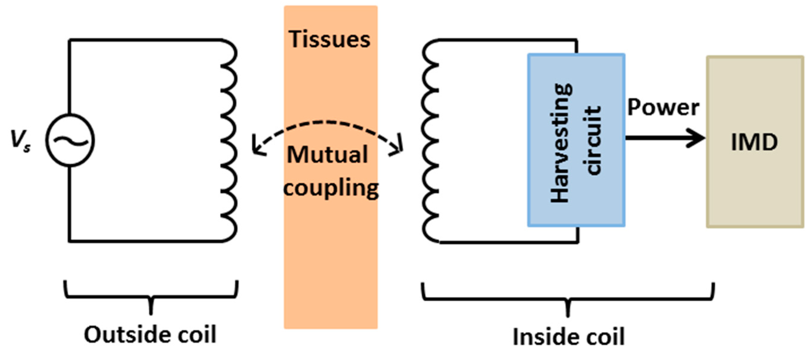
2.2.3. Inductive Coupling

It has been more than 180 years since Michael Faraday figured out power could be transferred through the air by magnetic induction. In 1914, wireless power and data transfer based on the magnetic coupling of two loops were initially reported by Tesla [128]. Recently, especially during the last decade, inductive coupling has been widely investigated to power up IMDs. The principle behind is based on a mutual inductance between two coils in which one is located outside the body while the other is integrated with the implanted device. As the external antenna transmits a varying electromagnetic signal, a voltage would be induced in the receiver coil (Figure 7). The wireless power efficiency depends on the resonance frequency (or operating frequency), distance, alignment, and coupling matching between the transmitter and the receiver coils [5,6,129,130,131,132]. In addition, the inductive technology can be exploited to transmitted data from outside to inside the body and vice-versa without using a radio-frequency (RF) transmitter or receiver with data rates up to few hundreds kilobits per second [5,6,121,133].
Figure 7. Inductive coupling overview.
Sensors 15 28889 g007
In their work, Parramon et al. developed an inductive coupling power source which could generate 19 mW at a carrier frequency of 10 MHz. This was used to power a microsystem for electromyography (EMG) recording implanted in rabbit muscle. The diameter of the inside coil, the diameter of the outside coil, and the distance between the two coil were 10 mm, 20 mm and 15 mm, respectively [134]. Another example was the use inductive coupling to power a wireless camera capsule for non-invasive visual inspection of the small bowel at a carrier frequency of 1 MHz [20]. This power source could generate up to 150 mW and the distance between the two coils was 205 mm. The size of the inside coil was 10 × 13 mm2. In 2004, Catrysse et al. presented an inductive link power source system which could deliver 50 mW over a 3 cm distance operating at 700 kHz in bench-top experiments [135]. Further, in 2007, Ghovanloo and Najafi demonstrated a system-on-chip (SOC) by combining application-specific integrated circuit (ASIC) design with off-chip components (LC tank; filters) delivering 50 mW over a 5 mm distance at 5/10 MHz frequency [136].
There are several essential factors in inductive coupling approach, such as misalignment, size of the implant antenna, unknown side effects and the limited carrier frequency due to tissue absorptions, thus low-megahertz ranges (0.3–30 MHz) have been widely used [5]. For further information about this approach, readers should refer to the Discussion section where inductive coupling is thoroughly discussed.

3. Discussion

3.1. Implantable Medical Devices: Roles and Future Expectations

With the rapid development of advanced technologies in the last decade, healthcare has been changed in several aspects. Nano- and wireless-technologies have transformed medical diagnosis, monitoring, and intervention into individualized care [6,137,138]. Definitions of self-care, e-care, mobile-health and the Internet of Things (IoTs) have emerged, changing the traditional roles of doctors and patients. People are capable of monitoring their health every day with innovative devices while large scale medical data could be assessed and diagnosed continuously by caregivers located thousands miles away. In many cases, the devices need to be inserted to stay safely and securely in the body for a period of time; thus a new expectation is raised for IMDs that the implant needs to be able to communicate with external units for real-time tracking and sensing, diagnosis and treatment. In order to achieve that, a sufficient power source becomes mandatory, no matter whether the device is active or passive.
In this upcoming scenario, power is needed not only for running the implant but also for feeding the high-consuming wireless communication, and this would concurrently drain out the battery of the implant and consequently reduce the lifetime of the device. A conceptual view of a future IMD is sketched in Figure 8. With these expectations, an IMD (1) can be powered from an external unit, such as a wearable belt (4) if the IMD is located in the abdomen or a hat (2) if the IMD is in the brain/head location. If there is a subcutaneous IMD in the arm/hand location, it can be powered by a wrist device (3). For wireless communications, IMDs can directly send data to a smartphone or via external units. Algorithms may be applied to filter, interpret and sort the data for diagnoses, storage or real-time examinations by distanced care-givers. Big data processes and mobile cloud systems will be needed to facilitate the infrastructure. We envision this will be the model of healthcare in the future which can significantly save time, and cost, providing efficiency and efficacy for our society. Obviously, in that dream picture, reliable micro-sensors and communication, durable power and systems as well as smart algorithms and designs, are essential. Other issues such as safety, usefulness, fashion and comfort also need to be improved in order to bring cutting-edge devices not only to patients but also the general public.
Figure 8. Overview of IMDs and other components. (1) Implant; (24) External devices.
Sensors 15 28889 g008

3.2. IMDs Power Source Approaches: Advantages and Limitations

Although there are challenges and issues that remain unsolved, IMDs have been useful and popular in healthcare applications such as medical monitoring and diagnostics. For example, a survey taken in 2009 involving 1,002,664 pacemakers and 328,027 ICDs, including new implants and replacements, found that the U.S. had the largest numbers, with 264,824 and 133,262 for pacemakers and ICDs, respectively [18]. In most cases, IMDs used non-regenerative power sources, namely batteries. To date, when safety is ensured with proper packaging, batteries still appear to be the most reliable power supply for IMDs when size, functionality and operation time are compromised. Compared with batteries, the most common issue for independent systems such as bio-fuel cells and thermoelectricity, is the low-output power while wireless powering systems add complications causing discomfort and none of the possible approaches could provide a reliability level which can be accepted in the stringent medical world.
However, sustainable sources to power chronic or life-time IMDs are still of high interest. There is another set of cases in which it is hard to access the implanted location (e.g., intravascular applications) and thus a biodegradable implant is favorable. Recent endeavors producing innovative biomaterials [139,140] have enabled the realization of those, but a batteryless solution for power using degradable materials needs to be defined. Table 1 briefly summarizes the different advantages, disadvantages, and power generation of power approaches for IMD applications.
Table 1. Power approaches for IMD applications.
Energy Harvesting MethodApproachesGenerated PowerReferencesAdvantagesDisadvantages
Independent systemLithium batteries210 W·h/kg[27]Compatibility with flexible electronicSize
300 W·h/kg[76]Toxicity
Bio-fuel cells2.4 μW[83]Recycle materialsLifetime
Biocompatibility with human bodyLow output power
Nuclear batteries50 μW[27]Longer service life (>15 years)Radioactive danger
Stable output energyExpensive
Thermoelectricity5.8 µW[91]Unlimited lifetimeLow output power
1 µW[92]
180 μW/cm2[93]
Piezoelectricity2.1–69.8 W[98] High output powerLimited implantable locations
0.33 μW[104]No additional voltage sourceBiocompatibility issues
1 W[46]
Electrostatic36 μW[54,109]High output powerAdditional voltage source
58 μW[54,109]High output impedance
80 µW[108]
Electromagnetic40–200 μW[112,113]Unlimited implantable locationsComplexity in fabrication technologies
1.1 mW[115]
400 μW[116]
Systems with external unitOptical charging22 mW/cm[119]High output powerLarge dimension
Ultrasonic transducer1.5 mW/cm2[124,126]Data transferLow output power
May be used for different depthsSide effects
Inductive coupling19 mW[134]High data rate and power transmissionLimited carrier frequency due to tissue absorptions
150 mW[20]
50 mW[135,136]No batteries neededSide effects
6.15 mW[141]
In an expected regular IMD of the coming era, the time of m-Health and IoTs, there will be pivotal components which are highly-sensitive biosensors, low-power integrated electronic circuits, low-power and reliable wireless communication, and obviously a sufficient power source. While the recent advances in nanotechnology and materials [2] have enabled the realization of smaller and more sensitive sensors consuming less energy as well as low-power and more compact electronics, the increasing need for communication and interaction with other devices and a mobile cloud requires much higher power to operate the new-generation devices. As a result, a catch-22 without an absolute solution yet is faced. Although tremendous effort has been spent by scientists in order to investigate approaches to either exploit human energy or remotely transfer the power, the proposed solutions still cannot provide enough energy to operate smaller-and-smaller devices with more-and-more functionalities. An illustration of a pacemaker with more than 80% of volume reserved for the battery has been a real obsession and challenge for scientists working in the field, not to mention the recent call for wireless communication for m-Health applications.
Recently, numerous novel bio-sensing mechanisms using DNA [142,143,144] have been proposed implying that hybrid systems in which electronics and biological elements are merged will be possible in the coming years. Such systems would definitely require very low power but bring the highest level of sensitivity and biocompatibility as they would not be treated as foreign objects in our biological environment, not to mention minimizing biofoulings and inflammatory responses. However, as wireless data communication is still a necessity, the challenging power issue remains unsolved. Although a large number of low-power and more-effective wireless communication methodologies and protocols have been invented recently, the mechanism has remained unchanged, with wireless chips, regular amplification circuits, filters, and converters dealing with electromagnetic waves at some frequency. This would always overwhelm a compact IMD.
Besides IMDs for uses in humans, implantable devices have been widely used with animal models for biological investigations and drug screening. While the safety issues are not comparable with those of devices used for humans, most of the animal models (i.e., mice, zebrafish, and rats) present more challenges due to their much smaller size. Consequently, the lessons taught by overcoming the obstacles in animal models can be translated to IMDs. For instance, the recent effort in providing a wireless electrocardiogram (ECG) monitoring system to elucidate heart regeneration in zebrafish and neonatal mice [145,146] could suggest a solution for implantable devices used with humans, in which power is inductively transferred while data is sent optically.

3.3. Inductive Coupling: Possibilities and Challenges

Wireless powering via a resonance-based inductive link has been extensively investigated for a wide range of applications in the recent years owing to the capability to provide sufficient power, the reliability and the possibility to integrate it with other electronic components. Further, the inductive link could also be exploited for data transmission [5,6,136]. In the domain of medical devices, numerous approaches were proposed with innovations in design, materials and circuits in order to target specific applications. For IMDs, the operating frequencies are usually in the low MHz or KHz range to minimize the power absorbed by the tissue which may cause tissue heating and side effects [6,135]. A number of studies have been carried out to improve the power transfer efficiency (PTE) of regular 2-coil systems [20,23,34,147,148,149], in which coil geometry, coil dimensions, number of turns, and coil losses were examined for optimization. Recently, MEMS technology and advanced materials have enabled the fabrication of miniaturized coils on either flexible or hard substrates, which could be integrated monolithically with other electronic components. While the problem of a smaller coil resulting in less coupled energy remains unsolved, we also face with another challenge that the thin fabricated metal film of the coil (usually <1 µm) would cause an extremely low quality factor (Q), and consequently low PTE. Our group recently proposed a solution using the low-temperature co-fired ceramic (LTCC) technology to cascade the spiral coils in multiple layers (up to 10 layers in LTCC) to improve PTE (results to be published). Utilizing LTCC, improvement was achieved not only from the higher number of turns by cascading but also from the thick metal layer (>8 µm) resulting in higher Qs. Although LTCC could bring enhance PTE as well as the capability of integration with electronics as well as lab-on-a-chip applications, the hard material and the high processing temperature restrict the use with numerous IMDs.
In practical scenarios, most anatomical surfaces are highly curved and most organs are relatively mobile during daily activities, requiring IMDs to be flexible and to remain functional. However, the inductance of the flexible coil antenna would change with respect to mechanical environmental cues, thus varying the resonance frequency of the LC tank in the IMD. If the changes are significant, the PTE would be reduced drastically. This calls for the implementation of an adaptive mechanism to ensure the resonant frequencies are matched on both sides [149,150,151]. However, this may add components to the room-limited IMDs. Another practical issue is misalignment which has been widely investigated [5,35,152]. For specific IMDs attached to moving organs such as the stomach, positional and angular misalignment becomes critical. Recent investigations have shown the superiority of spiral structures for transmitter antennas to produce a large-cover beam size, minimizing misalignment issues [153]. Nonetheless, misalignment is case-dependent and unavoidable, requiring thorough calibration and investigation in a simulated environment before actual use.
Instead of using a conventional 2-antenna system, multi-input and multi-output (MIMO) systems have been investigated [154,155,156]. Obviously, as the field is continuously active, multiple IMDs can be used simultaneously, however it would lead to a complicated case as it affects the mutual inductance between any two antennas and consequently, the PTE. Further, it is also difficult to place a ‘repeater’ to improve the PTE and distance, as mentioned in [157]. The most possible case that could help is using multiple transmitters with one receiver in an IMD [156]. For example, two or more transmitters can be located around the torso to increase the power sent to IMDs. Nevertheless, it would be hard to obtain constructive superposition and field optimization in dynamic cases with the inevitable daily activities of users.
It would be improper to not mention the biological effects caused in tissues by the electromagnetic field [41,158]. Although it has been studied, attention was paid mostly to the acute effects generated by heating, while long-term health issues are concerns preventing patients and the public from accepting and using IMDs with inductive coupling.

4. Conclusions

The limited lifespan and biocompatibility are the most serious issues with all power approaches used in IMDs. Alternative methods have been investigated extensively to replace existing conventional battery-based systems for powering IMDs. Towards this end, this review addresses a dual goal: (1) summarize various key power approaches for IMDs and highlight the strength and weakness of each one; (2) raise concerns and discuss trends in IMDs towards future medicine and healthcare applications. All approaches for harvesting energy with independent systems and with an external unit are reviewed and discussed. The independent system approach used the body environment energy such as body temperature and body motion to generate the electrical energy to power the IMDs. These approaches are based on thermoelectric, piezoelectric, electromagnetic and electrostatic effects, providing unlimited lifetime, but the low output power and the limited implant location choices represent the major challenges. On the other hand, the power approaches using an external unit such as optical charging, ultrasonic transducer and inductive coupling allow transferring the power and information data as well as enable the ability to power the IMD in different body locations. Democritus once stated: Everything existing in the universe is the fruit of chance and necessity”. Taking this message, we’ve fully understood the importance and significance of each approach to power IMD and highly appreciated invaluable contributions of scientists on the road towards a better life of our society.

Acknowledgments

This work is supported by the Natural Sciences and Engineering Research Council (NSERC), Canada.

Conflicts of Interest

The authors declare no conflict of interest.

References

  1. Price, C.P.; Kricka, L.J. Improving healthcare accessibility through point-of-care technologies. Clin. Chem. 2007, 53, 1665–1675. [Google Scholar] [PubMed]
  2. Kim, D.-H.; Lu, N.; Ma, R.; Kim, Y.-S.; Kim, R.-H.; Wang, S.; Wu, J.; Won, S.M.; Tao, H.; Islam, A. Epidermal electronics. Science 2011, 333, 838–843. [Google Scholar] [CrossRef] [PubMed]
  3. Cramer, J.A. Microelectronic systems for monitoring and enhancing patient compliance with medication regimens. Drugs 1995, 49, 321–327. [Google Scholar] [CrossRef] [PubMed]
  4. Sia, S.K.; Kricka, L.J. Microfluidics and point-of-care testing. Lab Chip 2008, 8, 1982–1983. [Google Scholar] [CrossRef] [PubMed]
  5. Cao, H.; Landge, V.; Tata, U.; Seo, Y.-S.; Rao, S.; Tang, S.-J.; Tibbals, H.; Spechler, S.; Chiao, J. An implantable, batteryless, and wireless capsule with integrated impedance and PH sensors for gastroesophageal reflux monitoring. IEEE Trans. Biomed. Eng. 2012, 59, 3131–3139. [Google Scholar] [PubMed]
  6. Cao, H.; Rao, S.; Tang, S.-J.; Tibbals, H.F.; Spechler, S.; Chiao, J.-C. Batteryless implantable dual-sensor capsule for esophageal reflux monitoring. Gastrointest. Endos. 2013, 77, 649–653. [Google Scholar] [CrossRef] [PubMed]
  7. Cao, H.; Yu, F.; Zhao, Y.; Scianmarello, N.; Lee, J.; Dai, W.; Jen, N.; Beebe, T.; Li, R.; Ebrahimi, R. Stretchable electrochemical impedance sensors for intravascular detection of lipid-rich lesions in new zealand white rabbits. Biosens. Bioelectron. 2014, 54, 610–616. [Google Scholar] [CrossRef] [PubMed]
  8. Webster, J.G. Design of Cardiac Pacemakers; IEEE Press: Piscataway, NJ, USA, 1995. [Google Scholar]
  9. Wilson, B.S.; Finley, C.C.; Lawson, D.T.; Wolford, R.D.; Eddington, D.K.; Rabinowitz, W.M. Better speech recognition with cochlear implants. Nature 1991, 352, 236–238. [Google Scholar] [CrossRef] [PubMed]
  10. Breit, S.; Schulz, J.B.; Benabid, A.-L. Deep brain stimulation. Cell Tissue Res. 2004, 318, 275–288. [Google Scholar] [CrossRef] [PubMed]
  11. Zeng, F.-G. Trends in cochlear implants. Trends Amplif. 2004, 8, 1–34. [Google Scholar] [CrossRef] [PubMed]
  12. Cao, H.; Li, A.-L.; Nguyen, C.M.; Peng, Y.-B.; Chiao, J.-C. An integrated flexible implantable micro-probe for sensing neurotransmitters. IEEE Sens. J. 2012, 12, 1618–1624. [Google Scholar] [CrossRef]
  13. Kringelbach, M.L.; Owen, S.L.; Aziz, T.Z. Deep-brain stimulation. 2007, 8, 623–635. [Google Scholar] [CrossRef] [PubMed]
  14. Kern, D.S.; Kumar, R. Deep brain stimulation. Neurologist 2007, 13, 237–252. [Google Scholar] [CrossRef] [PubMed]
  15. Sousa, J.E.; Costa, M.A.; Abizaid, A.; Abizaid, A.S.; Feres, F.; Pinto, I.M.; Seixas, A.C.; Staico, R.; Mattos, L.A.; Sousa, A.G. Lack of neointimal proliferation after implantation of sirolimus-coated stents in human coronary arteries a quantitative coronary angiography and three-dimensional intravascular ultrasound study. Circulation 2001, 103, 192–195. [Google Scholar] [CrossRef] [PubMed]
  16. Bloomfield, D.M.; Steinman, R.C.; Namerow, P.B.; Parides, M.; Davidenko, J.; Kaufman, E.S.; Shinn, T.; Curtis, A.; Fontaine, J.; Holmes, D. Microvolt t-wave alternans distinguishes between patients likely and patients not likely to benefit from implanted cardiac defibrillator therapy a solution to the multicenter automatic defibrillator implantation trial (MADIT) II conundrum. Circulation 2004, 110, 1885–1889. [Google Scholar] [CrossRef] [PubMed]
  17. Wood, M.A.; Ellenbogen, K.A. Cardiac pacemakers from the patient’s perspective. Circulation 2002, 105, 2136–2138. [Google Scholar] [CrossRef] [PubMed]
  18. Mond, H.G.; Proclemer, A. The 11th world survey of cardiac pacing and implantable cardioverter—Defibrillators: Calendar year 2009—A world society of arrhythmia’s project. Pacing Clin. Electrophysiol. 2011, 34, 1013–1027. [Google Scholar] [CrossRef] [PubMed]
  19. Antonioli, F.B.; Consiglio, F.; Grassi, G.; Lebrun, R.; Zanardi, F. Stimulatore cardiac impiantabile con nuova a stato solido al litio. Minerva 1973, 64, 2298–2305. [Google Scholar]
  20. Lenaerts, B.; Puers, R. An inductive power link for a wireless endoscope. Biosens. Bioelectron. 2007, 22, 1390–1395. [Google Scholar] [CrossRef] [PubMed]
  21. Silay, K.M.; Dondi, D.; Larcher, L.; Declercq, M.; Benini, L.; Leblebici, Y.; Dehollain, C. Load Optimization of an Inductive Power Link for Remote Powering of Biomedical Implants. In Proceedings of the IEEE International Symposium on Circuits and Systems, Taipei, Taiwan, 24–27 May 2009; pp. 533–536.
  22. De Donaldson, N.N.; Perkins, T. Analysis of resonant coupled coils in the design of radio frequency transcutaneous links. Med. Biol. Eng. Comput. 1983, 21, 612–627. [Google Scholar] [CrossRef]
  23. RamRakhyani, A.K.; Mirabbasi, S.; Chiao, M. Design and optimization of resonance-based efficient wireless power delivery systems for biomedical implants. IEEE Trans.Biomed. Circuits Syst. 2011, 5, 48–63. [Google Scholar] [CrossRef] [PubMed]
  24. Holmes, C.F. The role of lithium batteries in modern health care. J. Power Sour. 2001, 97, 739–741. [Google Scholar] [CrossRef]
  25. Holmes, C.F. The bourner lecture: Electrochemical power sources—An important contributor to modern health care. J. Power Sour. 1997, 65. [Google Scholar] [CrossRef]
  26. Nathan, M. Microbattery technologies for miniaturized implantable medical devices. Curr. Pharm. Biotechnol. 2010, 11, 404–410. [Google Scholar] [CrossRef] [PubMed]
  27. Wei, X.; Liu, J. Power sources and electrical recharging strategies for implantable medical devices. Front. Energy Power Eng. China 2008, 2, 1–13. [Google Scholar] [CrossRef]
  28. Schmidt, C.L.; Skarstad, P.M. The future of lithium and lithium-ion batteries in implantable medical devices. J. Power Sour. 2001, 97, 742–746. [Google Scholar] [CrossRef]
  29. Bock, D.C.; Marschilok, A.C.; Takeuchi, K.J.; Takeuchi, E.S. Batteries used to power implantable biomedical devices. Electrochim. Acta 2012, 84, 155–164. [Google Scholar] [CrossRef] [PubMed]
  30. Bullen, R.A.; Arnot, T.; Lakeman, J.; Walsh, F. Biofuel cells and their development. Biosens. Bioelectron. 2006, 21, 2015–2045. [Google Scholar] [CrossRef] [PubMed]
  31. Dong, K.; Jia, B.; Yu, C.; Dong, W.; Du, F.; Liu, H. Microbial fuel cell as power supply for implantable medical devices: A novel configuration design for simulating colonic environment. Biosens. Bioelectron. 2013, 41, 916–919. [Google Scholar] [CrossRef] [PubMed]
  32. Drews, J.; Fehrmann, G.; Staub, R.; Wolf, R. Primary batteries for implantable pacemakers and defibrillators. J. Power Sour. 2001, 97, 747–749. [Google Scholar] [CrossRef]
  33. Mallela, V.S.; Ilankumaran, V.; Rao, N.S. Trends in cardiac pacemaker batteries. Indian Pacing Electrophysiol. J. 2004, 4, 201. [Google Scholar] [PubMed]
  34. Fernandez, C.; Garcia, O.; Prieto, R.; Cobos, J.; Gabriels, S.; van der Borght, G. Design Issues of a Core-Less Transformer for a Contact-Less Application. In Proceedings of the Seventeenth Annual IEEE Applied Power Electronics Conference and Exposition, Dallas, TX, USA, 10–14 March 2002; pp. 339–345.
  35. Nguyen, M.Q.; Hughes, Z.; Woods, P.; Seo, Y.-S.; Rao, S.; Chiao, J.-C. Field distribution models of spiral coil for misalignment analysis in wireless power transfer systems. IEEE Trans. Microw. Theory Tech. 2014, 62, 920–930. [Google Scholar] [CrossRef]
  36. Parsonnet, V.; Cheema, A. The nature and frequency of postimplant surgical interventions. Pacing Clin. Electrophysiol. 2003, 26, 2308–2312. [Google Scholar] [CrossRef] [PubMed]
  37. Ko, W.H.; Hynecek, J. Implant evaluation of a nuclear power source-betacel battery. IEEE Trans. Biomed. Eng. 1974, 3, 238–241. [Google Scholar] [CrossRef] [PubMed]
  38. Parsonnet, V.; Villanueva, A.; Driller, J.; Bernstein, A.D. Corrosion of pacemaker electrodes. Pacing Clin. Electrophysiol. 1981, 4, 289–295. [Google Scholar] [CrossRef] [PubMed]
  39. Halliwell, C.M.; Simon, E.; Toh, C.-S.; Cass, A.E.; Bartlett, P.N. The design of dehydrogenase enzymes for use in a biofuel cell: The role of genetically introduced peptide tags in enzyme immobilization on electrodes. Bioelectrochemistry 2002, 55, 21–23. [Google Scholar] [CrossRef]
  40. Simon, E.; Halliwell, C.M.; Toh, C.S.; Cass, A.E.; Bartlett, P.N. Immobilisation of enzymes on poly (aniline)–poly (anion) composite films. Preparation of bioanodes for biofuel cell applications. Bioelectrochemistry 2002, 55, 13–15. [Google Scholar] [CrossRef]
  41. Meral, I.; Mert, H.; Mert, N.; Deger, Y.; Yoruk, I.; Yetkin, A.; Keskin, S. Effects of 900-MHz electromagnetic field emitted from cellular phone on brain oxidative stress and some vitamin levels of guinea pigs. Brain Res. 2007, 1169, 120–124. [Google Scholar] [CrossRef] [PubMed]
  42. Priya, S.; Inman, D.J. Energy Harvesting Technologies; Springer: Berlin, Germany, 2009. [Google Scholar]
  43. Vullers, R.; van Schaijk, R.; Doms, I.; van Hoof, C.; Mertens, R. Micropower energy harvesting. Solid State Electron. 2009, 53, 684–693. [Google Scholar] [CrossRef]
  44. Harb, A. Energy harvesting: State-of-the-art. Renew. Energy 2011, 36, 2641–2654. [Google Scholar] [CrossRef]
  45. Glynne-Jones, P.; Beeby, S.; White, N. Towards a piezoelectric vibration-powered microgenerator. IEE Proc. Sci. Meas. Technol. 2001, 148, 68–72. [Google Scholar] [CrossRef]
  46. Kymissis, J.; Kendall, C.; Paradiso, J.; Gershenfeld, N. Parasitic Power Parvesting in Phoes, Wearable Computers. In Proceedings of the IEEE Second International Symposium on Digest of Papers, Pittsburg, PA, USA, 19–20 October 1998; pp. 132–139.
  47. Kim, H.S.; Kim, J.-H.; Kim, J. A review of piezoelectric energy harvesting based on vibration. Int. J. Precis. Eng. Manuf. 2011, 12, 1129–1141. [Google Scholar] [CrossRef]
  48. Almouahed, S.; Gouriou, M.; Hamitouche, C.; Stindel, E.; Roux, C. Self-Powered Instrumented Knee Implant for Early Detection of Postoperative Complications. In Proceedings of the 2010 Annual International Conference of the IEEE Engineering in Medicine and Biology Society (EMBC), Piscataway, NJ, USA, 31 September 2010; pp. 5121–5124.
  49. Lahuec, C.; Almouahed, S.; Arzel, M.; Gupta, D.; Hamitouche, C.; Jezequel, M.; Stindel, E.; Roux, C. A self-powered telemetry system to estimate the postoperative instability of a knee implant. IEEE Trans. Biomed. Eng. 2011, 58, 822–825. [Google Scholar] [CrossRef] [PubMed]
  50. Almouahed, S.; Gouriou, M.; Hamitouche, C.; Stindel, E.; Roux, C. The use of piezoceramics as electrical energy harvesters within instrumented knee implant during walking. IEEE ASME Trans. Mechatron. 2011, 16, 799–807. [Google Scholar] [CrossRef]
  51. Beeby, S.P.; Tudor, M.J.; White, N. Energy harvesting vibration sources for microsystems applications. Meas. Sci. Technol. 2006, 17, 175–195. [Google Scholar] [CrossRef]
  52. Miao, P.; Holmes, A.; Yeatman, E.; Green, T.; Mitcheson, P. Micro-Machined Variable Capacitors for Power Generation. In Proceedings of the Conference Series-Institute of Physics, Edinburgh, Scotland, 23–27 March 2003; pp. 53–58.
  53. Miyazaki, M.; Tanaka, H.; Nagano, T.; Ohkubo, N.; Kawahara, T. Electric-energy generation through variable-capacitive resonator for power-free LSI. IEICE Trans. Electron. 2004, 87, 549–555. [Google Scholar]
  54. Tashiro, R.; Kabei, N.; Katayama, K.; Ishizuka, Y.; Tsuboi, F.; Tsuchiya, K. Development of an electrostatic generator that harnesses the motion of a living body. Use of a resonant phenomenon. JSME Int. J. Ser. C 2000, 43, 916–922. [Google Scholar] [CrossRef]
  55. Murakawa, K.; Kobayashi, M.; Nakamura, O.; Kawata, S. A wireless near-infrared energy system for medical implants. IEEE Eng. Med. Biol. Mag. 1999, 18, 70–72. [Google Scholar] [CrossRef] [PubMed]
  56. Penner, A. Acoustically Powered Implantable Stimulating Device. U.S. Patent US8577460 B2, 5 November 2013. [Google Scholar]
  57. Willis, N.P.; Brisken, A.F.; Cowan, M.W.; Pare, M.; Fowler, R.; Brennan, J. Optimizing Energy Transmission in a Leadless Tissue Stimulation System. U.S. Patent US8718773 B2, 6 May 2014. [Google Scholar]
  58. Tran, B.C.; Mi, B.; Harguth, R.S. Systems and Methods for Controlling Wireless Signal Transfers between Ultrasound-Enabled Medical Devices. U.S. Patent WO2009102640 A1, 5 February 2013. [Google Scholar]
  59. Ozeri, S.; Shmilovitz, D.; Singer, S.; Wang, C.-C. Ultrasonic transcutaneous energy transfer using a continuous wave 650 kHz gaussian shaded transmitter. Ultrasonics 2010, 50, 666–674. [Google Scholar] [CrossRef] [PubMed]
  60. Ozeri, S.; Shmilovitz, D. Ultrasonic transcutaneous energy transfer for powering implanted devices. Ultrasonics 2010, 50, 556–566. [Google Scholar] [CrossRef] [PubMed]
  61. Chen, K.; Yang, Z.; Hoang, L.; Weiland, J.; Humayun, M.; Liu, W. An integrated 256-channel epiretinal prosthesis. IEEE J. Solid State Circuits 2010, 45, 1946–1956. [Google Scholar] [CrossRef]
  62. Scrosati, B. History of lithium batteries. J. Solid State Electrochem. 2011, 15, 1623–1630. [Google Scholar] [CrossRef]
  63. Holmes, C. The lithium/iodine-polyvinylpyridine pacemaker battery-35 years of successful clinical use. ECS Trans. 2007, 6, 1–7. [Google Scholar]
  64. Linden, D.; Reddy, T.B. Handbook of Batteries, 3rd ed.; McGraw-Hill: New York, NY, USA, 2002. [Google Scholar]
  65. Nagao, M.; Pitteloud, C.; Kamiyama, T.; Otomo, T.; Itoh, K.; Fukunaga, T.; Kanno, R. Further understanding of reaction processes in electrolytic manganese dioxide electrodes for lithium cells. J. Electrochem. Soc. 2005, 152, E230–E237. [Google Scholar] [CrossRef]
  66. Johnson, C.S. Development and utility of manganese oxides as cathodes in lithium batteries. J. Power Sour. 2007, 165, 559–565. [Google Scholar] [CrossRef]
  67. Greatbatch, W.; Holmes, C.; Takeuchi, E.; Ebel, S. Lithium/carbon monofluoride (Li/CFx): A new pacemaker battery. Pacing Clin. Electrophysiol. 1996, 19, 1836–1840. [Google Scholar] [CrossRef] [PubMed]
  68. Amatucci, G.G.; Pereira, N. Fluoride based electrode materials for advanced energy storage devices. J. Fluor. Chem. 2007, 128, 243–262. [Google Scholar] [CrossRef]
  69. Davis, S.; Takeuchi, E.S.; Tiedemann, W.; Newman, J. Simulation of pulse discharge of the Li-CFx x system. J. Electrochem. Soc. 2008, 155, A24–A28. [Google Scholar] [CrossRef]
  70. Zhang, S.S.; Foster, D.; Read, J. Carbothermal treatment for the improved discharge performance of primary Li/CFx battery. J. Power Sour. 2009, 191, 648–652. [Google Scholar] [CrossRef]
  71. Takeuchi, E.S.; Piliero, P. Lithium/silver vanadium oxide batteries with various silver to vanadium ratios. J. Power Sour. 1987, 21, 133–141. [Google Scholar] [CrossRef]
  72. Kim, Y.J.; Lee, C.-Y.; Marschilok, A.C.; Takeuchi, K.J.; Takeuchi, E.S. AgxVOPO4: A demonstration of the dependence of battery-related electrochemical properties of silver vanadium phosphorous oxides on Ag/V ratios. J. Power Sour. 2011, 196, 3325–3330. [Google Scholar] [CrossRef] [PubMed]
  73. Crespi, A.; Schmidt, C.; Norton, J.; Chen, K.; Skarstad, P. Modeling and characterization of the resistance of lithium/SVO batteries for implantable cardioverter defibrillators. J. Electrochem. Soc. 2001, 148, A30–A37. [Google Scholar] [CrossRef]
  74. Chen, K.; Merritt, D.R.; Howard, W.G.; Schmidt, C.L.; Skarstad, P.M. Hybrid cathode lithium batteries for implantable medical applications. J. Power Sour. 2006, 162, 837–840. [Google Scholar] [CrossRef]
  75. Gomadam, P.M.; Merritt, D.R.; Scott, E.R.; Schmidt, C.L.; Skarstad, P.M.; Weidner, J.W. Modeling Li/CFx-SVO Hybrid-Cathode Batteries. J. Electrochem. Soc. 2007, 154, A1058–A1064. [Google Scholar] [CrossRef]
  76. Whittingham, M.S. Lithium batteries and cathode materials. Chem. Rev. 2004, 104, 4271–4302. [Google Scholar] [CrossRef] [PubMed]
  77. Rahimi-Eichi, H.; Baronti, F.; Chow, M.-Y. Online adaptive parameter identification and state-of-charge coestimation for lithium-polymer battery cells. IEEE Trans. Ind. Electron. 2014, 61, 2053–2061. [Google Scholar] [CrossRef]
  78. Gwon, H.; Hong, J.; Kim, H.; Seo, D.-H.; Jeon, S.; Kang, K. Recent progress on flexible lithium rechargeable batteries. Energy Environ. Sci. 2014, 7, 538–551. [Google Scholar] [CrossRef]
  79. Grove, W.R. Xxiv. On voltaic series and the combination of gases by platinum. Lond. Edinb. Philos. Mag. J. Sci. 1839, 14, 127–130. [Google Scholar]
  80. Potter, M.C. Electrical Effects Accompanying the Decomposition of Organic Compounds. In Proceedings of the Royal Society of London. Series B, Containing Papers of a Biological Character, London, UK, 14 September 1911; pp. 260–276.
  81. Cohen, B. The bacterial culture as an electrical half-cell. J. Bacteriol. 1931, 21, 18–19. [Google Scholar]
  82. Yahiro, A.; Lee, S.; Kimble, D. Bioelectrochemistry: I. Enzyme Utilizing Bio-Fuel Cell Studies. Biochim. Biophys. Acta Spec. Sect. Biophys. Subj. 1964, 88, 375–383. [Google Scholar] [CrossRef]
  83. Mano, N.; Mao, F.; Heller, A. Characteristics of a miniature compartment-less glucose-O2 biofuel cell and its operation in a living plant. J. Am. Chem. Soc. 2003, 125, 6588–6594. [Google Scholar] [CrossRef] [PubMed]
  84. Cadei, A.; Dionisi, A.; Sardini, E.; Serpelloni, M. Kinetic and thermal energy harvesters for implantable medical devices and biomedical autonomous sensors. Meas. Sci. Technol. 2014, 25. [Google Scholar] [CrossRef]
  85. Huesgen, T.; Woias, P.; Kockmann, N. Design and fabrication of mems thermoelectric generators with high temperature efficiency. Sens. Actuators A Phys. 2008, 145, 423–429. [Google Scholar] [CrossRef]
  86. Snyder, G.J. Thermoelectric energy harvesting. In Energy Harvesting Technologies; Springer: Berlin, Germany, 2009; pp. 325–336. [Google Scholar]
  87. Torfs, T.; Leonov, V.; Vullers, R. Pulse oximeter fully powered by human body heat. Sens. Transducers J. 2007, 80, 1230–1238. [Google Scholar]
  88. Yadav, A.; Pipe, K.; Shtein, M. Fiber-based flexible thermoelectric power generator. J. Power Sour. 2008, 175, 909–913. [Google Scholar] [CrossRef]
  89. Rowe, D.M. Crc Handbook of Thermoelectrics; CRC Press: Boca Raton, FL, USA, 1995. [Google Scholar]
  90. Xie, J.; Lee, C.; Feng, H. Design, fabrication, and characterization of cmos mems-based thermoelectric power generators. Microelectromech. Syst. J. 2010, 19, 317–324. [Google Scholar] [CrossRef]
  91. Stark, I.; Stordeur, M. New Micro Thermoelectric Devices Based on Bismuth Telluride-Type Thin Solid Films. In Proceedings of the Eighteenth International Conference on Thermoelectrics, Piscataway, NJ, USA, 29 August–2 September 1999; pp. 465–472.
  92. Strasser, M.; Aigner, R.; Lauterbach, C.; Sturm, T.; Franosch, M.; Wachutka, G. Micromachined cmos thermoelectric generators as on-chip power supply. Sens. Actuators A Phys. 2004, 114, 362–370. [Google Scholar] [CrossRef]
  93. Settaluri, K.T.; Lo, H.; Ram, R.J. Thin thermoelectric generator system for body energy harvesting. J. Electron. Mater. 2012, 41, 984–988. [Google Scholar] [CrossRef]
  94. Manbachi, A.; Cobbold, R.S. Development and application of piezoelectric materials for ultrasound generation and detection. Ultrasound 2011, 19, 187–196. [Google Scholar] [CrossRef]
  95. Anton, S.R.; Sodano, H.A. A review of power harvesting using piezoelectric materials (2003–2006). Smart Mater. Struct. 2007, 16, R1–R21. [Google Scholar] [CrossRef]
  96. Sodano, H.A.; Inman, D.J.; Park, G. A review of power harvesting from vibration using piezoelectric materials. Shock Vib. Dig. 2004, 36, 197–206. [Google Scholar] [CrossRef]
  97. González, J.L.; Rubio, A.; Moll, F. Human powered piezoelectric batteries to supply power to wearable electronic devices. Int. J. Soc. Mater. Eng. Resour. 2002, 10, 34–40. [Google Scholar] [CrossRef]
  98. Niu, P.; Chapman, P.; Riemer, R.; Zhang, X. Evaluation of Motions and Actuation Methods for Biomechanical Energy Harvesting. In Proceedings of the IEEE 35th Annual Power Electronics Specialists Conference, Aachen, Germany, 20–25 June 2004; pp. 2100–2106.
  99. Renaud, M.; Sterken, T.; Fiorini, P.; Puers, R.; Baert, K.; van Hoof, C. Scavenging Energy from Human Body: Design of a Piezoelectric Transducer. In Proceedings of the 13th International Conference on Solid-State Sensors, Actuators and Microsystems, Digest of Technical Papers, Seoul, Korea, 5–9 June 2005; pp. 784–787.
  100. Chen, H.; Liu, M.; Jia, C.; Wang, Z. Power harvesting using PZT ceramics embedded in orthopedic implants. IEEE Trans. Ultrason. Ferroelectr. Freq. Control 2009, 56, 2010–2014. [Google Scholar] [CrossRef] [PubMed]
  101. Platt, S.R.; Farritor, S.; Garvin, K.; Haider, H. The use of piezoelectric ceramics for electric power generation within orthopedic implants. IEEE ASME Trans. Mechatron. 2005, 10, 455–461. [Google Scholar] [CrossRef]
  102. Mateu, L.; Fonellosa, F.; Moll, F. Electrical Characterization of a Piezoelectric Film-Based Power Generator for Autonomous Wearable Devices. In Proceedings of the Conference on Design of Circuits and Integrated Systems, Albacete, Spain, 19–21 November 2013; pp. 677–682.
  103. Mateu, L.; Moll, F. Optimum piezoelectric bending beam structures for energy harvesting using shoe inserts. J. Intell. Mater. Syst. Struct. 2005, 16, 835–845. [Google Scholar] [CrossRef]
  104. Sohn, J.; Choi, S.B.; Lee, D. An investigation on piezoelectric energy harvesting for mems power sources. Proc. Inst. Mech. Eng. Part C J.Mech. Eng. Sci. 2005, 219, 429–436. [Google Scholar] [CrossRef]
  105. Cheng, D.K. Field and Wave Electromagnetics; Addison-Wesley: New York, NY, USA, 1989. [Google Scholar]
  106. Tsai, N.-C.; Sue, C.-Y. Review of mems-based drug delivery and dosing systems. Sens. Actuators A Phys. 2007, 134, 555–564. [Google Scholar] [CrossRef]
  107. Roundy, S.J. Energy Scavenging for Wireless Sensor Nodes with a Focus on Vibration to Electricity Conversion; University of California: Berkeley, CA, USA, 2003. [Google Scholar]
  108. Miao, P.; Mitcheson, P.; Holmes, A.; Yeatman, E.; Green, T.; Stark, B. Mems inertial power generators for biomedical applications. Microsyst. Technol. 2006, 12, 1079–1083. [Google Scholar] [CrossRef] [Green Version]
  109. Tashiro, R.; Kabei, N.; Katayama, K.; Tsuboi, E.; Tsuchiya, K. Development of an electrostatic generator for a cardiac pacemaker that harnesses the ventricular wall motion. J. Artif. Org. 2002, 5, 0239–0245. [Google Scholar] [CrossRef]
  110. Paulo, J.; Gaspar, P. Review and Future Trend of Energy Harvesting Methods for Portable Medical Devices. In Proceedings of the World Congress on Engineering, London, UK, 30 June–2 July 2010; pp. 168–196.
  111. Williams, C.; Yates, R.B. Analysis of a micro-electric generator for microsystems. Sens. Actuators A Phys. 1996, 52, 8–11. [Google Scholar] [CrossRef]
  112. Irani, A.; Bianco, M.; Tran, D.; Deyoung, P.D.; Wyld, M.L.R.; Li, T.H. Energy Generating Systems for Implanted Medical Devices. U.S. Patent US20090171404 A1, 2 July 2009. [Google Scholar]
  113. Goto, H.; Sugiura, T.; Harada, Y.; Kazui, T. Feasibility of using the automatic generating system for quartz watches as a leadless pacemaker power source. Med. Biol. Eng. Comput. 1999, 37, 377–380. [Google Scholar] [CrossRef] [PubMed]
  114. Roberts, P.; Stanley, G.; Morgan, J.M. Harvesting the energy of cardiac motion to power a pacemaker. Circulation 2008, 118, 679–680. [Google Scholar] [CrossRef]
  115. Nasiri, A.; Zabalawi, S.A.; Jeutter, D.C. A linear permanent magnet generator for powering implanted electronic devices. IEEE Trans. Power Electron. 2011, 26, 192–199. [Google Scholar] [CrossRef]
  116. Amirtharajah, R.; Chandrakasan, A.P. Self-powered signal processing using vibration-based power generation. IEEE J. Solid State Circuits 1998, 33, 687–695. [Google Scholar] [CrossRef]
  117. Parkhouse, L. Photovoltaic Powered Charging Apparatus for Implanted Rechargeable Batteries. U.S. Patent US7003353 B1, 21 February 2006. [Google Scholar]
  118. Lee, J.B.; Chen, Z.; Allen, M.G.; Rohatgi, A.; Arya, R. A miniaturized high-voltage solar cell array as an electrostatic mems power supply. Microelectromech. Syst. J. 1995, 4, 102–108. [Google Scholar] [CrossRef]
  119. Goto, K.; Nakagawa, T.; Nakamura, O.; Kawata, S. An implantable power supply with an optically rechargeable lithium battery. IEEE Trans. Biomed. Eng. 2001, 48, 830–833. [Google Scholar] [CrossRef] [PubMed]
  120. Jr Ackermann, D.M.; Smith, B.; Kilgore, K.L.; Peckham, P.H. Design of a High Speed Transcutaneous Optical Telemetry Link. In Proceedings of the 28th Annual International Conference of the IEEE Engineering in Medicine and Biology Society, New York, NY, USA, 30 August–3 September 2006; pp. 2932–2935.
  121. Olivo, J.; Carrara, S.; de Micheli, G. Energy harvesting and remote powering for implantable biosensors. IEEE Sens. J. 2011, 11, 1573–1586. [Google Scholar] [CrossRef]
  122. Banerji, S.; Goh, W.L.; Cheong, J.H.; Je, M. CMUT Ultrasonic Power Link Front-End for Wireless Power Transfer Deep in Body. In Proceedings of the IEEE MTT-S International Microwave Workshop Series on RF and Wireless Technologies for Biomedical and Healthcare Applications (IMWS-BIO), Singapore, 9–11 December 2013; pp. 1–3.
  123. Christensen, D.B.; Roundy, S. Ultrasonically powered piezoelectric generators for bio-implantable sensors: Plate versus diaphragm. J. Intell. Mater. Syst. Struct. 2015. [Google Scholar] [CrossRef]
  124. Cochran, G.V.; Kadaba, M.P.; Palmieri, V.R. External ultrasound can generate microampere direct currents in vivo from implanted piezoelectric materials. J. Orthop. Res. 1988, 6, 145–147. [Google Scholar] [CrossRef] [PubMed]
  125. Seo, D.; Carmena, J.M.; Rabaey, J.M.; Maharbiz, M.M.; Alon, E. Model validation of untethered, ultrasonic neural dust motes for cortical recording. J. Neurosci. Methods 2015, 244, 114–122. [Google Scholar] [CrossRef] [PubMed]
  126. Phillips, W.; Towe, B.; Larson, P. An Ultrasonically-Driven Piezoelectric Neural Stimulator. In Proceedings of the 25th Annual International Conference of the IEEE Engineering in Medicine and Biology Society, Cancun, Mexico, 17–21 September 2003; pp. 1983–1986.
  127. Kennedy, J.; Ter Haar, G.; Cranston, D. High intensity focused ultrasound: Surgery of the future? British J. Radiol. 2003, 76, 590–609. [Google Scholar] [CrossRef] [PubMed]
  128. Tesla, N. Apparatus for Transmitting Electrical Energy. U.S. Patent US1119732 A, 1 December 1914. [Google Scholar]
  129. Nishimura, T.H.; Eguchi, T.; Hirachi, K.; Maejima, Y.; Kuwana, K.; Saito, M. A Large Air Gap Flat Transformer for a Transcutaneous Energy Transmission System. In Proceedings of the 25th Annual IEEE Power Electronics Specialists Conference, PESC’94 Record, Taipei, Taiwan, 20–25 June 1994; pp. 1323–1329.
  130. Hui, S.; Zhong, W.; Lee, C. A critical review of recent progress in mid-range wireless power transfer. IEEE Trans.Power Electron. 2013, 29, 4500–4511. [Google Scholar] [CrossRef]
  131. Lee, H.-M.; Ghovanloo, M. A power-efficient wireless capacitor charging system through an inductive link. IEEE Trans. Circuits Syst. Express Br. 2013, 60, 707–711. [Google Scholar] [CrossRef] [PubMed]
  132. Neagu, C.; Jansen, H.; Smith, A.; Gardeniers, J.; Elwenspoek, M. Characterization of a planar microcoil for implantable microsystems. Sens. Actuators A Phys. 1997, 62, 599–611. [Google Scholar] [CrossRef]
  133. Cao, H.; Thakar, S.K.; Fu, T.; Sheth, M.; Oseng, M.L.; Landge, V.; Seo, Y.-S.; Chiao, J.-C. A Wireless Strain Sensor System for Bladder Volume Monitoring. In Proceedings of the IEEE MTT-S International Microwave Symposium Digest (MTT), Baltimore, MD, USA, 5–10 June 2011; pp. 1–4.
  134. Parramon, J.; Doguet, P.; Marin, D.; Verleyssen, M.; Munoz, R.; Leija, L.; Valderrama, E. Asic-Based Batteryless Implantable Telemetry Microsystem for Recording Purposes. Engineering in Medicine and Biology Society. In Proceedings of the 19th IEEE Annual International Conference, Chicago, IL, USA, 30 October–2 November 1997; pp. 2225–2228.
  135. Catrysse, M.; Hermans, B.; Puers, R. An inductive power system with integrated bi-directional data-transmission. Sens. Actuators A Phys. 2004, 115, 221–229. [Google Scholar] [CrossRef]
  136. Ghovanloo, M.; Najafi, K. A wireless implantable multichannel microstimulating system-on-a-chip with modular architecture. IEEE Trans. Neural Syst. Rehabil. Eng. 2007, 15, 449–457. [Google Scholar] [CrossRef] [PubMed]
  137. Bui, A.L.; Fonarow, G.C. Home monitoring for heart failure management. J. Am. Coll. Cardiol. 2012, 59, 97–104. [Google Scholar] [CrossRef] [PubMed]
  138. Cao, H.; Tata, U.; Landge, V.; Li, A.-L.; Peng, Y.-B.; Chiao, J.-C. A Wireless Bladder Volume Monitoring System Using a Flexible Capacitance-Based Sensor. In Proceedings of the Topical Conference on Biomedical Wireless Technologies, Networks, and Sensing Systems, Austin, TX, USA, 20–23 January 2013; pp. 34–36.
  139. Tran, R.T.; Choy, W.M.; Cao, H.; Qattan, I.; Chiao, J.C.; Ip, W.Y.; Yeung, K.W.K.; Yang, J. Fabrication and characterization of biomimetic multichanneled crosslinked-urethane-doped polyester tissue engineered nerve guides. J. Biomed. Mater. Rese. Part A 2014, 102, 2793–2804. [Google Scholar] [CrossRef] [PubMed]
  140. Kirkland, N.; Birbilis, N.; Staiger, M. Assessing the corrosion of biodegradable magnesium implants: A critical review of current methodologies and their limitations. Acta Biomater. 2012, 8, 925–936. [Google Scholar] [CrossRef] [PubMed]
  141. Li, P.; Bashirullah, R. A wireless power interface for rechargeable battery operated medical implants. IEEE Trans. Circuits Syst. II Express Br. 2007, 54, 912–916. [Google Scholar] [CrossRef]
  142. Galán, T.; Prieto-Simón, B.; Alvira, M.; Eritja, R.; Götz, G.; Bäuerle, P.; Samitier, J. Label-free electrochemical DNA sensor using “click”-functionalized pedot electrodes. Biosens. Bioelectron. 2015, 74, 751–756. [Google Scholar] [CrossRef] [PubMed]
  143. Weber, J.E.; Pillai, S.; Ram, M.K.; Kumar, A.; Singh, S.R. Electrochemical impedance-based DNA sensor using a modified single walled carbon nanotube electrode. Mater. Sci. Eng. C 2011, 31, 821–825. [Google Scholar] [CrossRef]
  144. Thipmanee, O.; Samanman, S.; Sankoh, S.; Numnuam, A.; Limbut, W.; Kanatharana, P.; Vilaivan, T.; Thavarungkul, P. Label-free capacitive DNA sensor using immobilized pyrrolidinyl pna probe: Effect of the length and terminating head group of the blocking thiols. Biosens. Bioelectron. 2012, 38, 430–435. [Google Scholar] [CrossRef] [PubMed]
  145. Cao, H.; Zhao, Y.; Kouki, A.B.; Tai, Y.-C.; Hsiai, T.K. A wireless ecg recording system for small animal models of heart regeneration. In Proceedings of the IEEE MTT-S International Microwave Symposium (IMS), Phoenix, AZ, USA, 17–22 May 2015; pp. 1–3.
  146. Cao, H.; Yu, F.; Zhao, Y.; Zhang, X.; Tai, J.; Lee, J.; Darehzereshki, A.; Bersohn, M.; Lien, C.-L.; Chi, N.C. Wearable multi-channel microelectrode membranes for elucidating electrophysiological phenotypes of injured myocardium. Integr. Biol. 2014, 6, 789–795. [Google Scholar] [CrossRef] [PubMed]
  147. Zierhofer, C.M.; Hochmair, E.S. Geometric approach for coupling enhancement of magnetically coupled coils. IEEE Trans. Biomed. Eng. 1996, 43, 708–714. [Google Scholar] [CrossRef] [PubMed]
  148. Zierhofer, C.M.; Hochmair, E.S. High-efficiency coupling-insensitive transcutaneous power and data transmission via an inductive link. IEEE Trans. Biomed. Eng. 1990, 37, 716–722. [Google Scholar] [CrossRef] [PubMed]
  149. Wang, G.; Liu, W.; Sivaprakasam, M.; Kendir, G.A. Design and analysis of an adaptive transcutaneous power telemetry for biomedical implants. IEEE Trans. Circuits Syst. I Regul. Pap. 2005, 52, 2109–2117. [Google Scholar] [CrossRef]
  150. Baarman, D.W. Adaptive Inductive Power Supply. U.S. Patent US7522878 B2, 21 April 2009. [Google Scholar]
  151. Sample, A.P.; Meyer, D.; Smith, J.R. Analysis, experimental results, and range adaptation of magnetically coupled resonators for wireless power transfer. IEEE Trans. Ind. Electron. 2011, 58, 544–554. [Google Scholar] [CrossRef]
  152. Fotopoulou, K.; Flynn, B.W. Wireless power transfer in loosely coupled links: Coil misalignment model. IEEE Trans. Magn. 2011, 47, 416–430. [Google Scholar] [CrossRef]
  153. Wu, W.; Fang, Q. Design and Simulation of Printed Spiral Coil Used in Wireless Power Transmission Systems for Implant Medical Devices. In Proceedings of the Annual International Conference of the IEEE Engineering in Medicine and Biology Society, Boston, Massachusetts USA, 30 August–3 September 2011; pp. 4018–4021.
  154. Nguyen, M.Q.; Chou, Y.; Plesa, D.; Rao, S.; Chiao, J. Multiple inputs and multiple outputs wireless power combining and delivering systems. IEEE Trans. Power Electron. 2015, 30, 6254–6263. [Google Scholar] [CrossRef]
  155. Yoon, I.-J.; Ling, H. Investigation of near-field wireless power transfer under multiple transmitters. IEEE Antennas Wirel. Propag. Lett. 2011, 10, 662–665. [Google Scholar] [CrossRef]
  156. Lee, K.; Cho, D.-H. Diversity analysis of multiple transmitters in wireless power transfer system. IEEE Trans. Magn. 2013, 49, 2946–2952. [Google Scholar] [CrossRef]
  157. Nguyen, M.Q.; Plesa, D.; Rao, S.; Chiao, J.-C. A Multi-Input and Multi-Output Wireless Energy Transfer System. In Proceedings of the IEEE MTT-S International Microwave Symposium (IMS), Tampa Bay, FL, USA, 1–6 Junuary 2014; pp. 1–3.
  158. Walleczek, J. Electromagnetic field effects on cells of the immune system: The role of calcium signaling. FASEB J. 1992, 6, 3177–3185. [Google Scholar] [PubMed]

