
Mesoporous Carbon-Based Materials for Enhancing the Performance of Lithium-Sulfur Batteries


 and
and 
Abstract
1. Introduction
2. Synthesis Strategies of MCBM
2.1. Soft Templates
2.2. Hard Templates

2.3. Soft/Hard Combined Templates


2.4. Template-Free Method

3. MCBM for Lithium-Sulfur Batteries
3.1. Application of MCBM in LSBs Anode
3.2. Application of MCBM in LSBs Cathode
3.2.1. Heteroatoms-Doped MCBM
3.2.2. Transition Metal Composite MCBM
3.2.3. Metal Oxide Composite MCBM
3.2.4. Metal Hydroxides Composite MCBM
3.2.5. Metal Sulfides Composite MCBM
3.2.6. Metal Nitrides Composite MCBM
3.2.7. Metal Carbides Composite MCBM
3.2.8. Metal Phosphates Composite MCBM
3.3. Application of MCBM in Separators or Interlayers
3.3.1. MCBM-Coated Separators for LSBs
3.3.2. MCBM Interlayers for LSBs
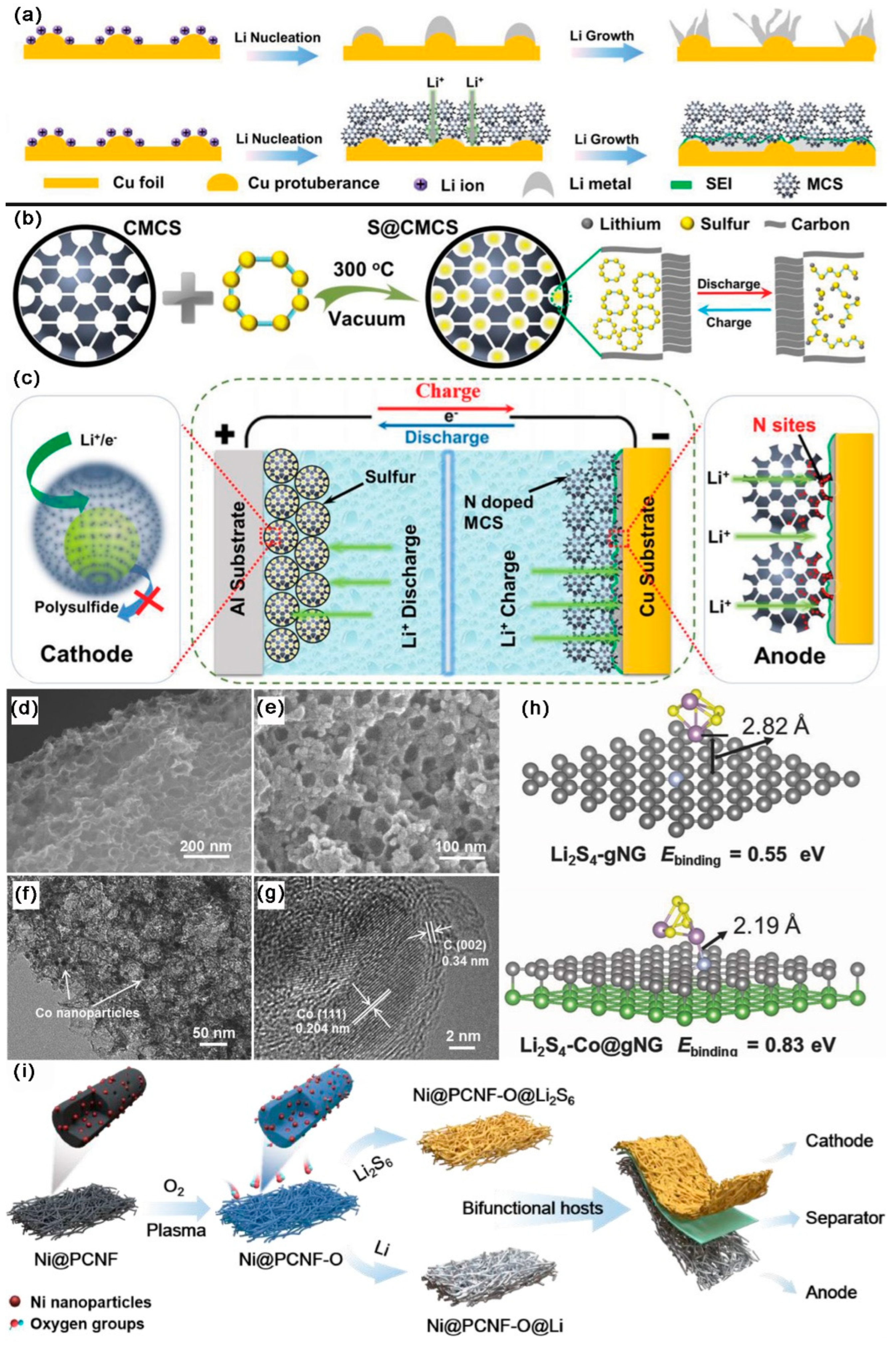
3.4. Application of MCBM as Two-in-One Hosts
4. Scientific Challenges and Future Prospects
- Ratio of S in Cathode
- 2.
- Areal S Loading
- 3.
- Electrolyte dosage
- 4.
- Li-S Pouch Cells
- 5.
- Safety
- 6.
- Cost
- 7.
- All Solid State LSBs
5. Conclusions
Author Contributions
Funding
Data Availability Statement
Conflicts of Interest
References
- Wang, L.; Wang, D.; Li, Y. Single-atom catalysis for carbon neutrality. Carbon Energy 2022, 4, 1021–1079. [Google Scholar] [CrossRef]
- He, P.; Zhang, T.; Jiang, J.; Zhou, H. Lithium-Air Batteries with Hybrid Electrolytes. J. Phys. Chem. Lett. 2016, 7, 1267–1280. [Google Scholar] [CrossRef] [PubMed]
- Chen, S.; Sun, B.; Xie, X.; Mondal, A.K.; Huang, X.; Wang, G. Multi-chambered micro/mesoporous carbon nanocubes as new polysulfides reserviors for lithium–sulfur batteries with long cycle life. Nano Energy 2015, 16, 268–280. [Google Scholar] [CrossRef]
- Ding, Y.-L.; Kopold, P.; Hahn, K.; van Aken, P.A.; Maier, J.; Yu, Y. Facile Solid-State Growth of 3D Well-Interconnected Nitrogen-Rich Carbon Nanotube-Graphene Hybrid Architectures for Lithium-Sulfur Batteries. Adv. Funct. Mater. 2016, 26, 1112–1119. [Google Scholar] [CrossRef]
- Yang, Y.; Zheng, G.; Cui, Y. Nanostructured sulfur cathodes. Chem. Soc. Rev. 2013, 42, 3018–3032. [Google Scholar] [CrossRef]
- Manthiram, A.; Chung, S.H.; Zu, C. Lithium-sulfur batteries: Progress and prospects. Adv. Mater. 2015, 27, 1980–2006. [Google Scholar] [CrossRef]
- Peng, H.-J.; Huang, J.-Q.; Cheng, X.-B.; Zhang, Q. Review on High-Loading and High-Energy Lithium-Sulfur Batteries. Adv. Energy Mater. 2017, 7, 1700260. [Google Scholar] [CrossRef]
- Wang, Z.; Shen, J.; Liu, J.; Xu, X.; Liu, Z.; Hu, R.; Yang, L.; Feng, Y.; Liu, J.; Shi, Z.; et al. Self-Supported and Flexible Sulfur Cathode Enabled via Synergistic Confinement for High-Energy-Density Lithium-Sulfur Batteries. Adv. Mater. 2019, 31, e1902228. [Google Scholar] [CrossRef]
- Li, C.; Xi, Z.; Guo, D.; Chen, X.; Yin, L. Chemical Immobilization Effect on Lithium Polysulfides for Lithium-Sulfur Batteries. Small 2018, 14, 1700260. [Google Scholar] [CrossRef]
- Wang, L.; Wang, Y.; Xia, Y. A high performance lithium-ion sulfur battery based on a Li2S cathode using a dual-phase electrolyte. Energy Environ. Sci. 2015, 8, 1551–1558. [Google Scholar] [CrossRef]
- Du, W.C.; Yin, Y.X.; Zeng, X.X.; Shi, J.L.; Zhang, S.F.; Wan, L.J.; Guo, Y.G. Wet Chemistry Synthesis of Multidimensional Nanocarbon-Sulfur Hybrid Materials with Ultrahigh Sulfur Loading for Lithium-Sulfur Batteries. ACS Appl. Mater. Interfaces 2016, 8, 3584–3590. [Google Scholar] [CrossRef]
- Guo, J.; Xu, Y.; Wang, C. Sulfur-impregnated disordered carbon nanotubes cathode for lithium-sulfur batteries. Nano Lett. 2011, 11, 4288–4294. [Google Scholar] [CrossRef] [PubMed]
- Seh, Z.W.; Sun, Y.; Zhang, Q.; Cui, Y. Designing high-energy lithium-sulfur batteries. Chem. Soc. Rev. 2016, 45, 5605–5634. [Google Scholar] [CrossRef] [PubMed]
- Li, H.; Ma, S.; Li, J.; Liu, F.; Zhou, H.; Huang, Z.; Jiao, S.; Kuang, Y. Altering the reaction mechanism to eliminate the shuttle effect in lithium-sulfur batteries. Energy Storage Mater. 2020, 26, 203–212. [Google Scholar] [CrossRef]
- Tao, X.; Liu, Y.; Liu, W.; Zhou, G.; Zhao, J.; Lin, D.; Zu, C.; Sheng, O.; Zhang, W.; Lee, H.W.; et al. Solid-State Lithium-Sulfur Batteries Operated at 37 degrees C with Composites of Nanostructured Li7La3Zr2O12/Carbon Foam and Polymer. Nano Lett. 2017, 17, 2967–2972. [Google Scholar] [CrossRef] [PubMed]
- Fang, R.; Zhao, S.; Sun, Z.; Wang, D.W.; Cheng, H.M.; Li, F. More Reliable Lithium-Sulfur Batteries: Status, Solutions and Prospects. Adv. Mater. 2017, 29, 06823. [Google Scholar] [CrossRef]
- Wei Seh, Z.; Li, W.; Cha, J.J.; Zheng, G.; Yang, Y.; McDowell, M.T.; Hsu, P.C.; Cui, Y. Sulphur-TiO2 yolk-shell nanoarchitecture with internal void space for long-cycle lithium-sulphur batteries. Nat. Commun. 2013, 4, 1331. [Google Scholar] [CrossRef]
- Singh, G.; Lee, J.; Karakoti, A.; Bahadur, R.; Yi, J.; Zhao, D.; AlBahily, K.; Vinu, A. Emerging trends in porous materials for CO2 capture and conversion. Chem. Soc. Rev. 2020, 49, 4360–4404. [Google Scholar] [CrossRef]
- Li, W.; Liu, J.; Zhao, D. Mesoporous materials for energy conversion and storage devices. Nat. Rev. Mater. 2016, 1, 23. [Google Scholar] [CrossRef]
- Zhang, Y.; Gong, S.; Zhang, Q.; Ming, P.; Wan, S.; Peng, J.; Jiang, L.; Cheng, Q. Graphene-based artificial nacre nanocomposites. Chem. Soc. Rev. 2016, 45, 2378–2395. [Google Scholar] [CrossRef]
- Guo, Y.; Tang, J.; Henzie, J.; Jiang, B.; Xia, W.; Chen, T.; Bando, Y.; Kang, Y.M.; Hossain, M.S.A.; Sugahara, Y.; et al. Mesoporous Iron-doped MoS2/CoMo2S4 Heterostructures through Organic-Metal Cooperative Interactions on Spherical Micelles for Electrochemical Water Splitting. ACS Nano 2020, 14, 4141–4152. [Google Scholar] [CrossRef] [PubMed]
- Wang, D.W.; Li, F.; Liu, M.; Lu, G.Q.; Cheng, H.M. 3D aperiodic hierarchical porous graphitic carbon material for high-rate electrochemical capacitive energy storage. Angew. Chem. Int. Ed. Engl. 2008, 47, 373–376. [Google Scholar] [CrossRef] [PubMed]
- Jiang, H.; Lee, P.S.; Li, C. 3D carbon based nanostructures for advanced supercapacitors. Energy Environ. Sci. 2013, 6, 41–53. [Google Scholar] [CrossRef]
- Zhang, J.; Dai, L. Heteroatom-Doped Graphitic Carbon Catalysts for Efficient Electrocatalysis of Oxygen Reduction Reaction. ACS Catal. 2015, 5, 7244–7253. [Google Scholar] [CrossRef]
- Balach, J.; Jaumann, T.; Klose, M.; Oswald, S.; Eckert, J.; Giebeler, L. Functional Mesoporous Carbon-Coated Separator for Long-Life, High-Energy Lithium-Sulfur Batteries. Adv. Funct. Mater. 2015, 25, 5285–5291. [Google Scholar] [CrossRef]
- Fan, Z.; Liu, Y.; Yan, J.; Ning, G.; Wang, Q.; Wei, T.; Zhi, L.; Wei, F. Template-Directed Synthesis of Pillared-Porous Carbon Nanosheet Architectures: High-Performance Electrode Materials for Supercapacitors. Adv. Energy Mater. 2012, 2, 419–424. [Google Scholar] [CrossRef]
- Liang, H.W.; Zhuang, X.; Bruller, S.; Feng, X.; Mullen, K. Hierarchically porous carbons with optimized nitrogen doping as highly active electrocatalysts for oxygen reduction. Nat. Commun. 2014, 5, 4973. [Google Scholar] [CrossRef]
- Liang, J.; Zhou, R.F.; Chen, X.M.; Tang, Y.H.; Qiao, S.Z. Fe-N decorated hybrids of CNTs grown on hierarchically porous carbon for high-performance oxygen reduction. Adv. Mater. 2014, 26, 6074–6079. [Google Scholar] [CrossRef] [PubMed]
- Zou, G.; Hou, H.; Foster, C.W.; Banks, C.E.; Guo, T.; Jiang, Y.; Zhang, Y.; Ji, X. Advanced Hierarchical Vesicular Carbon Co-Doped with S, P, N for High-Rate Sodium Storage. Adv. Sci. 2018, 5, 1800241. [Google Scholar] [CrossRef]
- Li, G.; Sun, J.; Hou, W.; Jiang, S.; Huang, Y.; Geng, J. Three-dimensional porous carbon composites containing high sulfur nanoparticle content for high-performance lithium-sulfur batteries. Nat. Commun. 2016, 7, 10601. [Google Scholar] [CrossRef]
- Zheng, C.; Niu, S.; Lv, W.; Zhou, G.; Li, J.; Fan, S.; Deng, Y.; Pan, Z.; Li, B.; Kang, F.; et al. Propelling polysulfides transformation for high-rate and long-life lithium–sulfur batteries. Nano Energy 2017, 33, 306–312. [Google Scholar] [CrossRef]
- Xu, H.; Li, H.; Xie, L.; Zhao, D.; Kong, B. Interfacial Assembly of Functional Mesoporous Carbon-Based Materials into Films for Batteries and Electrocatalysis. Adv. Mater. Interfaces 2022, 9, 01998. [Google Scholar] [CrossRef]
- Lyu, Z.; Lim, G.J.H.; Guo, R.; Pan, Z.; Zhang, X.; Zhang, H.; He, Z.; Adams, S.; Chen, W.; Ding, J.; et al. 3D-printed electrodes for lithium metal batteries with high areal capacity and high-rate capability. Energy Storage Mater. 2020, 24, 336–342. [Google Scholar] [CrossRef]
- Xiang, Y.; Lu, L.; Kottapalli, A.G.P.; Pei, Y. Status and perspectives of hierarchical porous carbon materials in terms of high-performance lithium–sulfur batteries. Carbon Energy 2022, 4, 346–398. [Google Scholar] [CrossRef]
- Ji, X.; Lee, K.T.; Nazar, L.F. A highly ordered nanostructured carbon-sulphur cathode for lithium-sulphur batteries. Nat. Mater. 2009, 8, 500–506. [Google Scholar] [CrossRef]
- Yang, Y.; McDowell, M.T.; Jackson, A.; Cha, J.J.; Hong, S.S.; Cui, Y. New nanostructured Li2S/silicon rechargeable battery with high specific energy. Nano Lett. 2010, 10, 1486–1491. [Google Scholar] [CrossRef]
- Li, X.; Cao, Y.; Qi, W.; Saraf, L.V.; Xiao, J.; Nie, Z.; Mietek, J.; Zhang, J.-G.; Schwenzer, B.; Liu, J. Optimization of mesoporous carbon structures for lithium–sulfur battery applications. J. Mater. Chem. 2011, 21, 16603. [Google Scholar] [CrossRef]
- Schuster, J.; He, G.; Mandlmeier, B.; Yim, T.; Lee, K.T.; Bein, T.; Nazar, L.F. Spherical ordered mesoporous carbon nanoparticles with high porosity for lithium-sulfur batteries. Angew. Chem. Int. Ed. Engl. 2012, 51, 3591–3595. [Google Scholar] [CrossRef]
- Xu, T.; Song, J.; Gordin, M.L.; Sohn, H.; Yu, Z.; Chen, S.; Wang, D. Mesoporous carbon-carbon nanotube-sulfur composite microspheres for high-areal-capacity lithium-sulfur battery cathodes. ACS Appl. Mater. Interfaces 2013, 5, 11355–11362. [Google Scholar] [CrossRef] [PubMed]
- Ma, G.; Wen, Z.; Jin, J.; Lu, Y.; Rui, K.; Wu, X.; Wu, M.; Zhang, J. Enhanced performance of lithium sulfur battery with polypyrrole warped mesoporous carbon/sulfur composite. J. Power Sources 2014, 254, 353–359. [Google Scholar] [CrossRef]
- You, Y.; Zeng, W.; Yin, Y.-X.; Zhang, J.; Yang, C.-P.; Zhu, Y.; Guo, Y.-G. Hierarchically micro/mesoporous activated graphene with a large surface area for high sulfur loading in Li–S batteries. J. Mater. Chem. A 2015, 3, 4799–4802. [Google Scholar] [CrossRef]
- Zhang, R.; Cheng, X.B.; Zhao, C.Z.; Peng, H.J.; Shi, J.L.; Huang, J.Q.; Wang, J.; Wei, F.; Zhang, Q. Conductive Nanostructured Scaffolds Render Low Local Current Density to Inhibit Lithium Dendrite Growth. Adv. Mater. 2016, 28, 2155–2162. [Google Scholar] [CrossRef] [PubMed]
- Zheng, J.; Guo, G.; Li, H.; Wang, L.; Wang, B.; Yu, H.; Yan, Y.; Yang, D.; Dong, A. Elaborately Designed Micro–Mesoporous Graphitic Carbon Spheres as Efficient Polysulfide Reservoir for Lithium–Sulfur Batteries. ACS Energy Lett. 2017, 2, 1105–1114. [Google Scholar] [CrossRef]
- Kang, W.; Fan, L.; Deng, N.; Zhao, H.; Li, Q.; Naebe, M.; Yan, J.; Cheng, B. Sulfur-embedded porous carbon nanofiber composites for high stability lithium-sulfur batteries. Chem. Eng. J. 2018, 333, 185–190. [Google Scholar] [CrossRef]
- Xie, J.; Li, B.Q.; Peng, H.J.; Song, Y.W.; Zhao, M.; Chen, X.; Zhang, Q.; Huang, J.Q. Implanting Atomic Cobalt within Mesoporous Carbon toward Highly Stable Lithium-Sulfur Batteries. Adv. Mater. 2019, 31, e1903813. [Google Scholar] [CrossRef]
- Zhang, Y.; Li, G.; Wang, J.; Cui, G.; Wei, X.; Shui, L.; Kempa, K.; Zhou, G.; Wang, X.; Chen, Z. Hierarchical Defective Fe3−xC@C Hollow Microsphere Enables Fast and Long-Lasting Lithium–Sulfur Batteries. Adv. Funct. Mater. 2020, 30, 2001165. [Google Scholar] [CrossRef]
- Liu, J.; Li, H.; Wang, J.; Zhang, Y.; Luo, D.; Zhao, Y.; Li, Y.; Yu, A.; Wang, X.; Chen, Z. Design Zwitterionic Amorphous Conjugated Micro-/Mesoporous Polymer Assembled Nanotentacle as Highly Efficient Sulfur Electrocatalyst for Lithium-Sulfur Batteries. Adv. Energy Mater. 2021, 11, 2101926. [Google Scholar] [CrossRef]
- Li, Y.; Zeng, Y.; Chen, Y.; Luan, D.; Gao, S.; Lou, X.W.D. Mesoporous N-rich Carbon with Single-Ni Atoms as a Multifunctional Sulfur Host for Li-S Batteries. Angew. Chem. Int. Ed. Engl. 2022, 61, e202212680. [Google Scholar] [PubMed]
- Kresge, C.T.; Leonowicz, M.E.; Roth, W.J.; Vartuli, J.C.; Beck, J.S. Ordered mesoporous molecular-sieves synthesized by a liquid-crystal template mechanism. Nature 1992, 359, 710–712. [Google Scholar] [CrossRef]
- Zu, L.; Zhang, W.; Qu, L.; Liu, L.; Li, W.; Yu, A.; Zhao, D. Mesoporous Materials for Electrochemical Energy Storage and Conversion. Adv. Energy Mater. 2020, 10, 2002152. [Google Scholar] [CrossRef]
- Liang, C.; Hong, K.; Guiochon, G.A.; Mays, J.W.; Dai, S. Synthesis of a large-scale highly ordered porous carbon film by self-assembly of block copolymers. Angew. Chem. Int. Ed. Engl. 2004, 43, 5785–5789. [Google Scholar] [CrossRef]
- Huang, Y.; Cai, H.; Yu, T.; Sun, X.; Tu, B.; Zhao, D. Highly ordered mesoporous carbonaceous frameworks from a template of a mixed amphiphilic triblock-copolymer system of PEO-PPO-PEO and reverse PPO-PEO-PPO. Chem. Asian J. 2007, 2, 1282–1289. [Google Scholar] [CrossRef]
- Liu, D.; Zeng, C.; Qu, D.; Tang, H.; Li, Y.; Su, B.-L.; Qu, D. Highly efficient synthesis of ordered nitrogen-doped mesoporous carbons with tunable properties and its application in high performance supercapacitors. J. Power Sources 2016, 321, 143–154. [Google Scholar] [CrossRef]
- Zhao, Z.; Duan, L.; Zhao, Y.; Wang, L.; Zhang, J.; Bu, F.; Sun, Z.; Zhang, T.; Liu, M.; Chen, H.; et al. Constructing Unique Mesoporous Carbon Superstructures via Monomicelle Interface Confined Assembly. J. Am. Chem. Soc. 2022, 144, 11767–11777. [Google Scholar] [CrossRef]
- Zhou, Y.; Yu, Y.; Ma, D.; Foucher, A.C.; Xiong, L.; Zhang, J.; Stach, E.A.; Yue, Q.; Kang, Y. Atomic Fe Dispersed Hierarchical Mesoporous Fe–N–C Nanostructures for an Efficient Oxygen Reduction Reaction. ACS Catal. 2020, 11, 74–81. [Google Scholar] [CrossRef]
- Duan, L.; Wang, C.; Zhang, W.; Ma, B.; Deng, Y.; Li, W.; Zhao, D. Interfacial Assembly and Applications of Functional Mesoporous Materials. Chem. Rev. 2021, 121, 14349–14429. [Google Scholar] [CrossRef] [PubMed]
- Zhao, T.; Elzatahry, A.; Li, X.; Zhao, D. Single-micelle-directed synthesis of mesoporous materials. Nat. Rev. Mater. 2019, 4, 775–791. [Google Scholar] [CrossRef]
- Zhao, Z.; Zhao, Y.; Lin, R.; Ma, Y.; Wang, L.; Liu, L.; Lan, K.; Zhang, J.; Chen, H.; Liu, M.; et al. Modular super-assembly of hierarchical superstructures from monomicelle building blocks. Sci. Adv. 2022, 8, 0283. [Google Scholar] [CrossRef]
- Xie, L.; Yan, M.; Liu, T.; Gong, K.; Luo, X.; Qiu, B.; Zeng, J.; Liang, Q.; Zhou, S.; He, Y.; et al. Kinetics-Controlled Super-Assembly of Asymmetric Porous and Hollow Carbon Nanoparticles as Light-Sensitive Smart Nanovehicles. J. Am. Chem. Soc. 2022, 144, 1634–1646. [Google Scholar] [CrossRef]
- Ryoo, R.; Joo, S.H.; Jun, S. Synthesis of highly ordered carbon molecular sieves via template-mediated structural transformation. J. Phys. Chem. B 1999, 103, 7743–7746. [Google Scholar] [CrossRef]
- Deng, Y.; Liu, C.; Yu, T.; Liu, F.; Zhang, F.; Wan, Y.; Zhang, L.; Wang, C.; Tu, B.; Webley, P.A.; et al. Facile synthesis of hierarchically porous carbons from dual colloidal crystal/block copolymer template approach. Chem. Mater. 2007, 19, 3271–3277. [Google Scholar] [CrossRef]
- Lee, J.; Yoon, S.; Hyeon, T.; Oh, S.M.; Kim, K.B. Synthesis of a new mesoporous carbon and its application to electrochemical double-layer capacitors. Chem. Commun. 1999, 35, 2177–2178. [Google Scholar] [CrossRef]
- Jun, S.; Joo, S.H.; Ryoo, R.; Kruk, M.; Jaroniec, M.; Liu, Z.; Ohsuna, T.; Terasaki, O. Synthesis of new, nanoporous carbon with hexagonally ordered mesostructure. J. Am. Chem. Soc. 2000, 122, 10712–10713. [Google Scholar] [CrossRef]
- Pang, J.; John, V.T.; Loy, D.A.; Yang, Z.; Lu, Y. Hierarchical Mesoporous Carbon/Silica Nanocomposites from Phenyl-Bridged Organosilane. Adv. Mater. 2005, 17, 704–707. [Google Scholar] [CrossRef]
- Lin, T.; Chen, I.W.; Liu, F.; Yang, C.; Bi, H.; Xu, F.; Huang, F. Nitrogen-doped mesoporous carbon of extraordinary capacitance for electrochemical energy storage. Science 2015, 350, 1508–1513. [Google Scholar] [CrossRef]
- Li, J.; Wang, N.; Tian, J.; Qian, W.; Chu, W. Cross-Coupled Macro-Mesoporous Carbon Network toward Record High Energy-Power Density Supercapacitor at 4 V. Adv. Funct. Mater. 2018, 28, 1806153. [Google Scholar] [CrossRef]
- Qian, S.; Wu, X.; Shi, Z.; Li, X.; Sun, X.; Ma, Y.; Sun, W.; Guo, C.; Li, C. Tuning electrospinning hierarchically porous nanowires anode for enhanced bioelectrocatalysis in microbial fuel cells. Nano Res. 2022, 15, 5089–5097. [Google Scholar] [CrossRef]
- Li, H.; Sakamoto, Y.; Li, Y.; Terasaki, O.; Thommes, M.; Che, S. Synthesis of carbon replicas of SBA-1 and SBA-7 mesoporous silicas. Microporous Mesoporous Mater. 2006, 95, 193–199. [Google Scholar] [CrossRef]
- Jeong, U.; Kim, H.; Ramesh, S.; Dogan, N.A.; Wongwilawan, S.; Kang, S.; Park, J.; Cho, E.S.; Yavuz, C.T. Rapid Access to Ordered Mesoporous Carbons for Chemical Hydrogen Storage. Angew. Chem. Int. Ed. Engl. 2021, 60, 22478–22486. [Google Scholar] [CrossRef] [PubMed]
- Sivaraman, N.; Duraisamy, V.; Senthil Kumar, S.M.; Thangamuthu, R. N, S dual doped mesoporous carbon assisted simultaneous electrochemical assay of emerging water contaminant hydroquinone and catechol. Chemosphere 2022, 307, 135771. [Google Scholar] [CrossRef]
- Jaroniec, M.; Gorka, J.; Choma, J.; Zawislak, A. Synthesis and properties of mesoporous carbons with high loadings of inorganic species. Carbon 2009, 47, 3034–3040. [Google Scholar] [CrossRef]
- Cao, J.; Yin, X.; Wang, L.; Guo, M.; Xu, J.; Chen, Z. Enhanced electrocatalytic activity of platinum nanoparticles supported on nitrogen-modified mesoporous carbons for methanol electrooxidation. Int. J. Hydrog. Energy 2015, 40, 2971–2978. [Google Scholar] [CrossRef]
- Xi, X.; Wu, D.; Han, L.; Yu, Y.; Su, Y.; Tang, W.; Liu, R. Highly Uniform Carbon Sheets with Orientation-Adjustable Ordered Mesopores. ACS Nano 2018, 12, 5436–5444. [Google Scholar] [CrossRef] [PubMed]
- Wang, K.; Zhang, W.; Phelan, R.; Morris, M.A.; Holmes, J.D. Direct fabrication of well-aligned free-standing mesoporous carbon nanofiber arrays on silicon substrates. J. Am. Chem. Soc. 2007, 129, 13388–13389. [Google Scholar] [CrossRef] [PubMed]
- Zhao, Q.; Wang, X.; Liu, J.; Wang, H.; Zhang, Y.; Gao, J.; Lu, Q.; Zhou, H. Design and synthesis of three-dimensional hierarchical ordered porous carbons for supercapacitors. Electrochim. Acta 2015, 154, 110–118. [Google Scholar] [CrossRef]
- Lee, J.S.; Wang, X.; Luo, H.; Baker, G.A.; Dai, S. Facile Ionothermal Synthesis of Microporous and Mesoporous Carbons from Task Specific Ionic Liquids. J. Am. Chem. Soc. 2009, 131, 4596–4597. [Google Scholar] [CrossRef] [PubMed]
- Tao, X.; Chen, X.; Xia, Y.; Huang, H.; Gan, Y.; Wu, R.; Chen, F.; Zhang, W. Highly mesoporous carbon foams synthesized by a facile, cost-effective and template-free Pechini method for advanced lithium–sulfur batteries. J. Mater. Chem. A 2013, 1, 3295–3301. [Google Scholar] [CrossRef]
- Ferrero, G.A.; Fuertes, A.B.; Sevilla, M.; Titirici, M.-M. Efficient metal-free N-doped mesoporous carbon catalysts for ORR by a template-free approach. Carbon 2016, 106, 179–187. [Google Scholar] [CrossRef]
- Chen, C.; Huang, H.; Yu, Y.; Shi, J.; He, C.; Albilali, R.; Pan, H. Template-free synthesis of hierarchical porous carbon with controlled morphology for CO2 efficient capture. Chem. Eng. J. 2018, 353, 584–594. [Google Scholar] [CrossRef]
- Zheng, Y.; Chen, S.; Zhang, K.A.I.; Guan, J.; Yu, X.; Peng, W.; Song, H.; Zhu, J.; Xu, J.; Fan, X.; et al. Template-free construction of hollow mesoporous carbon spheres from a covalent triazine framework for enhanced oxygen electroreduction. J. Colloid Interface Sci. 2022, 608, 3168–3177. [Google Scholar] [CrossRef]
- Tian, W.; Zhang, H.; Sun, H.; Tadé, M.O.; Wang, S. Template-free synthesis of N-doped carbon with pillared-layered pores as bifunctional materials for supercapacitor and environmental applications. Carbon 2017, 118, 98–105. [Google Scholar] [CrossRef]
- Xu, R.; Tang, H.; Zhou, Y.; Wang, F.; Wang, H.; Shao, M.; Li, C.; Wei, Z. Enhanced catalysis of radical-to-polysulfide interconversion via increased sulfur vacancies in lithium-sulfur batteries. Chem. Sci. 2022, 13, 6224–6232. [Google Scholar] [CrossRef] [PubMed]
- Pei, F.; Fu, A.; Ye, W.; Peng, J.; Fang, X.; Wang, M.S.; Zheng, N. Robust Lithium Metal Anodes Realized by Lithiophilic 3D Porous Current Collectors for Constructing High-Energy Lithium-Sulfur Batteries. ACS Nano 2019, 13, 8337–8346. [Google Scholar] [CrossRef] [PubMed]
- Liu, Y.; Qin, X.; Zhang, S.; Huang, Y.; Kang, F.; Chen, G.; Li, B. Oxygen and nitrogen co-doped porous carbon granules enabling dendrite-free lithium metal anode. Energy Storage Mater. 2019, 18, 320–327. [Google Scholar] [CrossRef]
- Jeong, J.; Chun, J.; Lim, W.G.; Kim, W.B.; Jo, C.; Lee, J. Mesoporous carbon host material for stable lithium metal anode. Nanoscale 2020, 12, 11818–11824. [Google Scholar] [CrossRef]
- Liu, L.; Yin, Y.-X.; Li, J.-Y.; Li, N.-W.; Zeng, X.-X.; Ye, H.; Guo, Y.-G.; Wan, L.-J. Free-Standing Hollow Carbon Fibers as High-Capacity Containers for Stable Lithium Metal Anodes. Joule 2017, 1, 563–575. [Google Scholar] [CrossRef]
- Li, Z.; Li, X.; Zhou, L.; Xiao, Z.; Zhou, S.; Zhang, X.; Li, L.; Zhi, L. A synergistic strategy for stable lithium metal anodes using 3D fluorine-doped graphene shuttle-implanted porous carbon networks. Nano Energy 2018, 49, 179–185. [Google Scholar] [CrossRef]
- Lu, Y.; Lu, Y.; Jin, C.; Gao, R.; Liu, B.; Huang, Y.; Yu, Y.; Ren, J.; Deng, Y.; Tao, X.; et al. Natural Wood Structure Inspires Practical Lithium–Metal Batteries. ACS Energy Lett. 2021, 6, 2103–2110. [Google Scholar] [CrossRef]
- Chen, Y.; Zou, K.; Dai, X.; Bai, H.; Zhang, S.; Zhou, T.; Li, C.; Liu, Y.; Pang, W.K.; Guo, Z. Polysulfide Filter and Dendrite Inhibitor: Highly Graphitized Wood Framework Inhibits Polysulfide Shuttle and Lithium Dendrites in Li–S Batteries. Adv. Funct. Mater. 2021, 31, 2102458. [Google Scholar] [CrossRef]
- Tang, Q.; Li, H.; Zuo, M.; Zhang, J.; Huang, Y.; Bai, P.; Xu, J.; Zhou, K. Optimized Assembly of Micro-/Meso-/Macroporous Carbon for Li–S Batteries. Nano 2017, 12, 1750021. [Google Scholar] [CrossRef]
- Liang, C.; Dudney, N.J.; Howe, J.Y. Hierarchically Structured Sulfur/Carbon Nanocomposite Material for High-Energy Lithium Battery. Chem. Mater. 2009, 21, 4724–4730. [Google Scholar] [CrossRef]
- Lu, Q.; Jie, Y.; Meng, X.; Omar, A.; Mikhailova, D.; Cao, R.; Jiao, S.; Lu, Y.; Xu, Y. Carbon materials for stable Li metal anodes: Challenges, solutions, and outlook. Carbon Energy 2021, 3, 957–975. [Google Scholar] [CrossRef]
- Hou, J.; Tu, X.; Wu, X.; Shen, M.; Wang, X.; Wang, C.; Cao, C.; Pang, H.; Wang, G. Remarkable cycling durability of lithium-sulfur batteries with interconnected mesoporous hollow carbon nanospheres as high sulfur content host. Chem. Eng. J. 2020, 401, 126141. [Google Scholar] [CrossRef]
- Zhang, L.; Zhao, W.; Yuan, S.; Jiang, F.; Chen, X.; Yang, Y.; Ge, P.; Sun, W.; Ji, X. Engineering the morphology/porosity of oxygen-doped carbon for sulfur host as lithium-sulfur batteries. J. Energy Chem. 2021, 60, 531–545. [Google Scholar] [CrossRef]
- Nitze, F.; Fossum, K.; Xiong, S.; Matic, A.; Palmqvist, A.E.C. Sulfur-doped ordered mesoporous carbons: A stability-improving sulfur host for lithium-sulfur battery cathodes. J. Power Sources 2016, 317, 112–119. [Google Scholar] [CrossRef]
- Dörfler, S.; Strubel, P.; Jaumann, T.; Troschke, E.; Hippauf, F.; Kensy, C.; Schökel, A.; Althues, H.; Giebeler, L.; Oswald, S.; et al. On the mechanistic role of nitrogen-doped carbon cathodes in lithium-sulfur batteries with low electrolyte weight portion. Nano Energy 2018, 54, 116–128. [Google Scholar] [CrossRef]
- Duan, L.; Zhao, L.; Cong, H.; Zhang, X.; Lu, W.; Xue, C. Plasma Treatment for Nitrogen-Doped 3D Graphene Framework by a Conductive Matrix with Sulfur for High-Performance Li-S Batteries. Small 2019, 15, e1804347. [Google Scholar] [CrossRef] [PubMed]
- Luo, R.; Xi, B.; Wei, R.; Chen, W.; Ma, X.; Feng, Z.; Feng, J.; Xiong, S. N-Doped graphitic ladder-structured carbon nanotubes as a superior sulfur host for lithium–sulfur batteries. Inorg. Chem. Front. 2020, 7, 3969–3979. [Google Scholar] [CrossRef]
- Zhang, F.; Ji, S.; Wang, H.; Liang, H.; Wang, X.; Wang, R. Implanting Cobalt Atom Clusters within Nitrogen-Doped Carbon Network as Highly Stable Cathode for Lithium-Sulfur Batteries. Small Methods 2021, 5, e2100066. [Google Scholar] [CrossRef]
- Hu, H.; Chen, H.; Wang, W.; Li, S.; Zhang, Y.; Liu, J.; Zheng, Y. Synthesis of nickel@N-doped carbon nanotube foams for high sulfur-loading lithium-sulfur battery. J. Alloy. Compd. 2022, 922, 166263. [Google Scholar] [CrossRef]
- Sun, F.; Qu, Z.; Wang, H.; Liu, X.; Pei, T.; Han, R.; Gao, J.; Zhao, G.; Lu, Y. Vapor deposition of aluminium oxide into N-rich mesoporous carbon framework as a reversible sulfur host for lithium-sulfur battery cathode. Nano Res. 2020, 14, 131–138. [Google Scholar] [CrossRef]
- Liu, Y.; Chen, M.; Hu, M.; Gao, Y.f.; Zhang, Y.; Long, D. In-situ anchoring sulfiphilic silica nanoparticles onto macro-mesoporous carbon framework for cost-effective Li-S cathodes. Chem. Eng. J. 2021, 406, 126781. [Google Scholar] [CrossRef]
- Qiu, P.; Yao, Y.; Li, W.; Sun, Y.; Jiang, Z.; Mei, B.; Gu, L.; Zhang, Q.; Shang, T.; Yu, X.; et al. Sub-nanometric Manganous Oxide Clusters in Nitrogen Doped Mesoporous Carbon Nanosheets for High-Performance Lithium-Sulfur Batteries. Nano Lett 2021, 21, 700–708. [Google Scholar] [CrossRef] [PubMed]
- Zeng, P.; Yu, H.; Liu, H.; Li, Y.; Zhou, Z.; Zhou, X.; Guo, C.; Li, B.; Chen, M.; Luo, Z.; et al. Enhancing Reaction Kinetics of Sulfur-Containing Species in Li-S Batteries by Quantum Dot-Level Tin Oxide Hydroxide Catalysts. ACS Appl. Energy Mater. 2021, 4, 4935–4944. [Google Scholar] [CrossRef]
- Yan, S.; Wu, J.; Dai, Y.; Pan, Z.; Sheng, W.; Xu, J.; Song, K. Excellent electrochemical application of Ni-based hydroxide/biomass porous carbon/sulfur composite cathode on lithium-sulfur batteries. Colloids Surf. A Physicochem. Eng. Asp. 2020, 591, 124513. [Google Scholar] [CrossRef]
- Yang, Z.; Zhao, Z.; Zhou, H.; Cheng, M.; Yan, R.; Tao, X.; Li, S.; Liu, X.; Cheng, C.; Ran, F. Cobalt-Based Double Catalytic Sites on Mesoporous Carbon as Reversible Polysulfide Catalysts for Fast-Kinetic Li-S Batteries. ACS Appl Mater Interfaces 2021, 13, 51174–51185. [Google Scholar] [CrossRef]
- Wang, H.-E.; Li, X.; Qin, N.; Zhao, X.; Cheng, H.; Cao, G.; Zhang, W. Sulfur-deficient MoS2 grown inside hollow mesoporous carbon as a functional polysulfide mediator. J. Mater. Chem. A 2019, 7, 12068–12074. [Google Scholar] [CrossRef]
- Wu, Q.; Yao, Z.; Zhou, X.; Xu, J.; Cao, F.; Li, C. Built-In Catalysis in Confined Nanoreactors for High-Loading Li-S Batteries. ACS Nano 2020, 14, 3365–3377. [Google Scholar] [CrossRef]
- Ye, C.; Zhang, L.; Guo, C.; Li, D.; Vasileff, A.; Wang, H.; Qiao, S.Z. A 3D Hybrid of Chemically Coupled Nickel Sulfide and Hollow Carbon Spheres for High Performance Lithium–Sulfur Batteries. Adv. Funct. Mater. 2017, 27, 1702524. [Google Scholar] [CrossRef]
- Xing, Z.; Li, G.; Sy, S.; Chen, Z. Recessed deposition of TiN into N-doped carbon as a cathode host for superior Li-S batteries performance. Nano Energy 2018, 54, 1–9. [Google Scholar] [CrossRef]
- Qiao, L.; Ren, L.; Zhang, R.; Chen, J.; Xu, M.; Liu, J.; Xu, H.; Liu, W.; Chang, Z.; Sun, X. Hollow Carbon Spheres Embedded with VN Quantum Dots as an Efficient Cathode Host for Lithium–Sulfur Batteries. Energy Fuels 2021, 35, 10219–10226. [Google Scholar] [CrossRef]
- Wang, Y.; Zhang, R.; Pang, Y.-c.; Chen, X.; Lang, J.; Xu, J.; Xiao, C.; Li, H.; Xi, K.; Ding, S. Carbon@titanium nitride dual shell nanospheres as multi-functional hosts for lithium sulfur batteries. Energy Storage Mater. 2019, 16, 228–235. [Google Scholar] [CrossRef]
- Shen, S.; Xia, X.; Zhong, Y.; Deng, S.; Xie, D.; Liu, B.; Zhang, Y.; Pan, G.; Wang, X.; Tu, J. Implanting Niobium Carbide into Trichoderma Spore Carbon: A New Advanced Host for Sulfur Cathodes. Adv. Mater. 2019, 31, e1900009. [Google Scholar] [CrossRef] [PubMed]
- Hu, X.; Shen, K.; Han, C.; Li, M.; Guo, J.; Yan, M.; Zhang, M. Rational design of ultrathin Mo2C/C nanosheets decorated on mesoporous hollow carbon spheres as a multifunctional sulfur host for advanced Li-S batteries. J. Alloy. Compd. 2022, 918, 165667. [Google Scholar] [CrossRef]
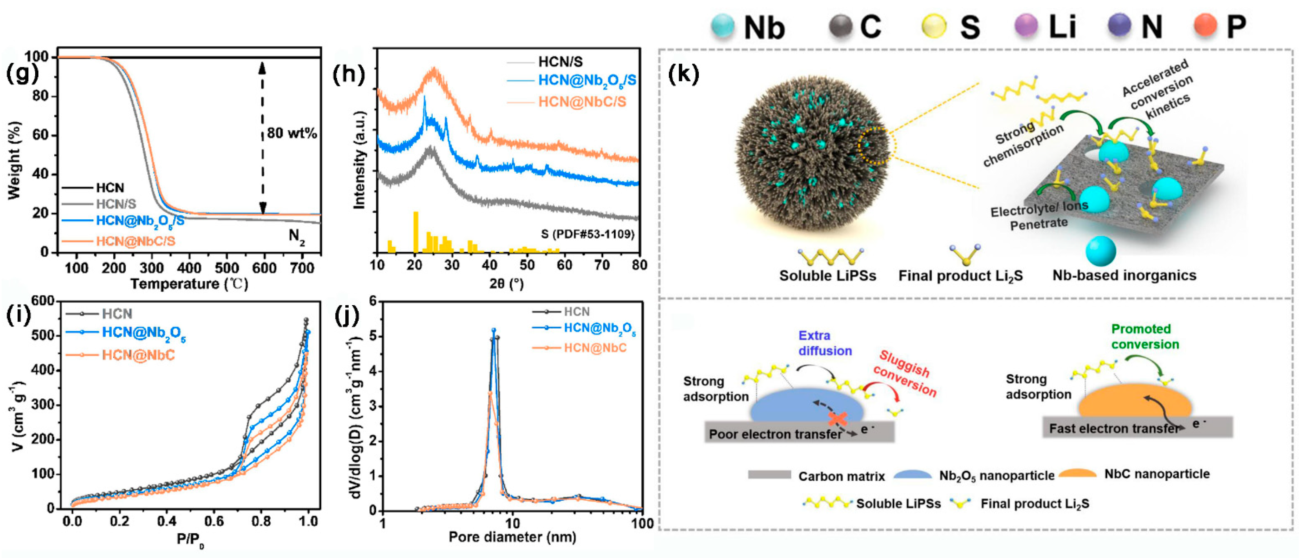
- Huang, Q.; Chen, M.; Su, Z.; Tian, L.; Zhang, Y.; Long, D. Rational cooperativity of nanospace confinement and rapid catalysis via hollow carbon nanospheres@Nb-based inorganics for high-rate Li-S batteries. Chem. Eng. J. 2021, 411, 128504. [Google Scholar] [CrossRef]
- Luo, Y.; Fan, Y.; Wang, S.; Chen, Q.; Ali, A.; Zhu, J.; Kang Shen, P. Cobalt phosphide embedded in a 3D carbon frame as a sulfur carrier for high-performance lithium-sulfur batteries. J. Electroanal. Chem. 2022, 912, 116202. [Google Scholar] [CrossRef]
- Xia, G.; Zheng, Z.; Ye, J.; Li, X.; Biggs, M.J.; Hu, C. Carbon microspheres with embedded FeP nanoparticles as a cathode electrocatalyst in Li-S batteries. Chem. Eng. J. 2021, 406, 126823. [Google Scholar] [CrossRef]
- Wang, R.; Yang, J.; Chen, X.; Zhao, Y.; Zhao, W.; Qian, G.; Li, S.; Xiao, Y.; Chen, H.; Ye, Y.; et al. Highly Dispersed Cobalt Clusters in Nitrogen-Doped Porous Carbon Enable Multiple Effects for High-Performance Li-S Battery. Adv. Energy Mater. 2020, 10, 1903550. [Google Scholar] [CrossRef]
- Lin, L.; Pei, F.; Peng, J.; Fu, A.; Cui, J.; Fang, X.; Zheng, N. Fiber network composed of interconnected yolk-shell carbon nanospheres for high-performance lithium-sulfur batteries. Nano Energy 2018, 54, 50–58. [Google Scholar] [CrossRef]
- Cheng, R.; Guan, Y.; Luo, Y.; Zhang, C.; Xia, Y.; Wei, S.; Zhao, M.; Lin, Q.; Li, H.; Zheng, S.; et al. Guanine-assisted N-doped ordered mesoporous carbons as efficient capacity decaying suppression materials for lithium–sulfur batteries. J. Mater. Sci. Technol. 2022, 101, 155–164. [Google Scholar] [CrossRef]
- Zhe, R.; Zhu, T.; Wei, X.; Ren, Y.; Qing, C.; Li, N.; Wang, H.-E. Graphene oxide wrapped hollow mesoporous carbon spheres as a dynamically bipolar host for lithium–sulfur batteries. J. Mater. Chem. A 2022, 10, 24422–24433. [Google Scholar] [CrossRef]
- Jin, S.; Wang, M.; Zhong, Y.; Wang, X.; Gu, C.; Xia, X.; Tu, J. A nitrogen-doped carbon skeleton derived from biomass as conductive agent for electrochemically stable cathode of all-solid-state lithium-sulfur batteries. Mater. Today Sustain. 2023, 21, 100281. [Google Scholar] [CrossRef]
- Lim, W.G.; Mun, Y.; Cho, A.; Jo, C.; Lee, S.; Han, J.W.; Lee, J. Synergistic Effect of Molecular-Type Electrocatalysts with Ultrahigh Pore Volume Carbon Microspheres for Lithium-Sulfur Batteries. ACS Nano 2018, 12, 6013–6022. [Google Scholar] [CrossRef] [PubMed]
- Sun, F.; Wang, J.; Long, D.; Qiao, W.; Ling, L.; Lv, C.; Cai, R. A high-rate lithium–sulfur battery assisted by nitrogen-enriched mesoporous carbons decorated with ultrafine La2O3 nanoparticles. J. Mater. Chem. A 2013, 1, 13283. [Google Scholar] [CrossRef]
- Zou, K.; Zhou, T.; Chen, Y.; Xiong, X.; Jing, W.; Dai, X.; Shi, M.; Li, N.; Sun, J.; Zhang, S.; et al. Defect Engineering in a Multiple Confined Geometry for Robust Lithium–Sulfur Batteries. Adv. Energy Mater. 2022, 12, 2103981. [Google Scholar] [CrossRef]
- Ni, L.; Zhao, G.; Yang, G.; Niu, G.; Chen, M.; Diao, G. Dual Core-Shell-Structured S@C@MnO2 Nanocomposite for Highly Stable Lithium-Sulfur Batteries. ACS Appl. Mater. Interfaces 2017, 9, 34793–34803. [Google Scholar] [CrossRef]
- Rehman, S.; Tang, T.; Ali, Z.; Huang, X.; Hou, Y. Integrated Design of MnO(2) @Carbon Hollow Nanoboxes to Synergistically Encapsulate Polysulfides for Empowering Lithium Sulfur Batteries. Small 2017, 13, 087. [Google Scholar]
- Lee, K.T.; Black, R.; Yim, T.; Ji, X.; Nazar, L.F. Surface-Initiated Growth of Thin Oxide Coatings for Li-Sulfur Battery Cathodes. Adv. Energy Mater. 2012, 2, 1490–1496. [Google Scholar] [CrossRef]
- Zhao, J.; Qi, Y.; Yang, Q.; Huang, T.; Wang, H.; Wang, Y.; Niu, Y.; Liu, Y.; Bao, S.; Xu, M. Chessboard structured electrode design for Li-S batteries Based on MXene nanosheets. Chem. Eng. J. 2022, 429, 131997. [Google Scholar] [CrossRef]
- Wang, H.; Li, S.; Li, D.; Chen, Z.; Liu, H.K.; Guo, Z. TiO 2 coated three-dimensional hierarchically ordered porous sulfur electrode for the lithium/sulfur rechargeable batteries. Energy 2014, 75, 597–602. [Google Scholar] [CrossRef]
- Gao, X.; Zhou, D.; Chen, Y.; Wu, W.; Su, D.; Li, B.; Wang, G. Strong charge polarization effect enabled by surface oxidized titanium nitride for lithium-sulfur batteries. Commun. Chem. 2019, 2, 0166–0168. [Google Scholar] [CrossRef]
- Oschatz, M.; Thieme, S.; Borchardt, L.; Lohe, M.R.; Biemelt, T.; Bruckner, J.; Althues, H.; Kaskel, S. A new route for the preparation of mesoporous carbon materials with high performance in lithium-sulphur battery cathodes. Chem. Commun. 2013, 49, 5832–5834. [Google Scholar] [CrossRef] [PubMed]
- Song, X.; Gao, T.; Wang, S.; Bao, Y.; Chen, G.; Ding, L.-X.; Wang, H. Free-standing sulfur host based on titanium-dioxide-modified porous-carbon nanofibers for lithium-sulfur batteries. J. Power Sources 2017, 356, 172–180. [Google Scholar] [CrossRef]
- Balach, J.; Jaumann, T.; Muhlenhoff, S.; Eckert, J.; Giebeler, L. Enhanced polysulphide redox reaction using a RuO2 nanoparticle-decorated mesoporous carbon as functional separator coating for advanced lithium-sulphur batteries. Chem. Commun. 2016, 52, 8134–8137. [Google Scholar] [CrossRef]
- Liu, Y.; Ma, Z.; Yang, G.; Wu, Z.; Li, Y.; Gu, J.; Gautam, J.; Gong, X.; Chishti, A.N.; Duan, S.; et al. Multifunctional ZnCo2O4 Quantum Dots Encapsulated In Carbon Carrier for Anchoring/Catalyzing Polysulfides and Self-Repairing Lithium Metal Anode in Lithium-Sulfur Batteries. Adv. Funct. Mater. 2021, 32, 2109462. [Google Scholar] [CrossRef]
- Tao, Y.; Wei, Y.; Liu, Y.; Wang, J.; Qiao, W.; Ling, L.; Long, D. Kinetically-enhanced polysulfide redox reactions by Nb2O5 nanocrystals for high-rate lithium–sulfur battery. Energy Environ. Sci. 2016, 9, 3230–3239. [Google Scholar] [CrossRef]
- Park, S.K.; Lee, J.; Hwang, T.; Jang, B.; Piao, Y. Scalable Synthesis of Honeycomb-like Ordered Mesoporous Carbon Nanosheets and Their Application in Lithium-Sulfur Batteries. ACS Appl. Mater. Interfaces 2017, 9, 2430–2438. [Google Scholar] [CrossRef]
- Jiang, S.; Chen, M.; Wang, X.; Wu, Z.; Zeng, P.; Huang, C.; Wang, Y. MoS2-Coated N-doped Mesoporous Carbon Spherical Composite Cathode and CNT/Chitosan Modified Separator for Advanced Lithium Sulfur Batteries. ACS Sustain. Chem. Eng. 2018, 6, 16828–16837. [Google Scholar] [CrossRef]
- Walle, M.D.; Zeng, K.; Zhang, M.; Li, Y.; Liu, Y.-N. Flower-like molybdenum disulfide/carbon nanotubes composites for high sulfur utilization and high-performance lithium–sulfur battery cathodes. Appl. Surf. Sci. 2019, 473, 540–547. [Google Scholar] [CrossRef]
- Shao, Q.; Lu, P.; Xu, L.; Guo, D.; Gao, J.; Wu, Z.-S.; Chen, J. Rational design of MoS2 nanosheets decorated on mesoporous hollow carbon spheres as a dual-functional accelerator in sulfur cathode for advanced pouch-type Li–S batteries. J. Energy Chem. 2020, 51, 262–271. [Google Scholar] [CrossRef]
- Zhong, Y.; Chao, D.; Deng, S.; Zhan, J.; Fang, R.; Xia, Y.; Wang, Y.; Wang, X.; Xia, X.; Tu, J. Confining Sulfur in Integrated Composite Scaffold with Highly Porous Carbon Fibers/Vanadium Nitride Arrays for High-Performance Lithium-Sulfur Batteries. Adv. Funct. Mater. 2018, 28, 1706391. [Google Scholar] [CrossRef]
- Huang, H.; Liu, J.; Xia, Y.; Cheng, C.; Liang, C.; Gan, Y.; Zhang, J.; Tao, X.; Zhang, W. Supercritical fluid assisted synthesis of titanium carbide particles embedded in mesoporous carbon for advanced Li–S batteries. J. Alloy. Compd. 2017, 706, 227–233. [Google Scholar] [CrossRef]
- Li, Y.; Xu, P.; Chen, G.; Mou, J.; Xue, S.; Li, K.; Zheng, F.; Dong, Q.; Hu, J.; Yang, C.; et al. Enhancing Li–S redox kinetics by fabrication of a three dimensional Co/CoP@nitrogen-doped carbon electrocatalyst. Chem. Eng. J. 2020, 380, 122595. [Google Scholar] [CrossRef]
- Zhang, C.; Du, R.; Biendicho, J.J.; Yi, M.; Xiao, K.; Yang, D.; Zhang, T.; Wang, X.; Arbiol, J.; Llorca, J.; et al. Tubular CoFeP@CN as a Mott–Schottky Catalyst with Multiple Adsorption Sites for Robust Lithium-Sulfur Batteries. Adv. Energy Mater. 2021, 11, 2100432. [Google Scholar] [CrossRef]
- Doan, T.L.L.; Nguyen, D.C.; Amaral, R.; Dzade, N.Y.; Kim, C.S.; Park, C.H. Rationally designed NiS2-MnS/MoS2 hybridized 3D hollow N-Gr microsphere framework-modified celgard separator for highly efficient Li-S batteries. Appl. Catal. B Environ. 2022, 319, 121934. [Google Scholar] [CrossRef]
- Luo, R.; Zhang, Z.; Zhang, J.; Xi, B.; Tian, F.; Chen, W.; Feng, J.; Xiong, S. Bimetal CoNi Active Sites on Mesoporous Carbon Nanosheets to Kinetically Boost Lithium-Sulfur Batteries. Small 2021, 17, e2100414. [Google Scholar] [CrossRef]
- Liu, S.; Li, C.; Liu, D. Modified Separator Based on mesoporous carbon/TiO2 composites as Advanced Polysulfide Adsorber for High Electrochemical Performance Li-S Batteries. J. Alloy. Compd. 2021, 862, 158381. [Google Scholar] [CrossRef]
- Liu, L.; Li, Y.; Zhang, Y.; Qiao, Z.; Lin, L.; Yan, X.; Meng, Z.; Huang, Y.; Lin, J.; Wang, L.; et al. CoP@C with chemisorption-catalysis effect toward lithium polysulfides as multifunctional interlayer for high-performance lithium-sulfur batteries. Electrochim. Acta 2022, 419, 140391. [Google Scholar] [CrossRef]
- Wang, J.; Yang, Y.; Kang, F. Porous carbon nanofiber paper as an effective interlayer for high-performance lithium-sulfur batteries. Electrochim. Acta 2015, 168, 271–276. [Google Scholar] [CrossRef]
- Li, H.; Cheng, Z.; Natan, A.; Hafez, A.M.; Cao, D.; Yang, Y.; Zhu, H. Dual-Function, Tunable, Nitrogen-Doped Carbon for High-Performance Li Metal-Sulfur Full Cell. Small 2019, 15, e1804609. [Google Scholar] [CrossRef]
- Liu, S.; Li, J.; Yan, X.; Su, Q.; Lu, Y.; Qiu, J.; Wang, Z.; Lin, X.; Huang, J.; Liu, R.; et al. Superhierarchical Cobalt-Embedded Nitrogen-Doped Porous Carbon Nanosheets as Two-in-One Hosts for High-Performance Lithium-Sulfur Batteries. Adv. Mater. 2018, 30, e1706895. [Google Scholar] [CrossRef] [PubMed]
- Ouyang, Y.; Zong, W.; Wang, J.; Xu, Z.; Mo, L.; Lai, F.; Xu, Z.-L.; Miao, Y.-E.; Liu, T. Multi-scale uniform Li regulation triggered by tunable electric field distribution on oxygen-functionalized porous framework for flexible Li–S full batteries. Energy Storage Mater. 2021, 42, 68–77. [Google Scholar] [CrossRef]
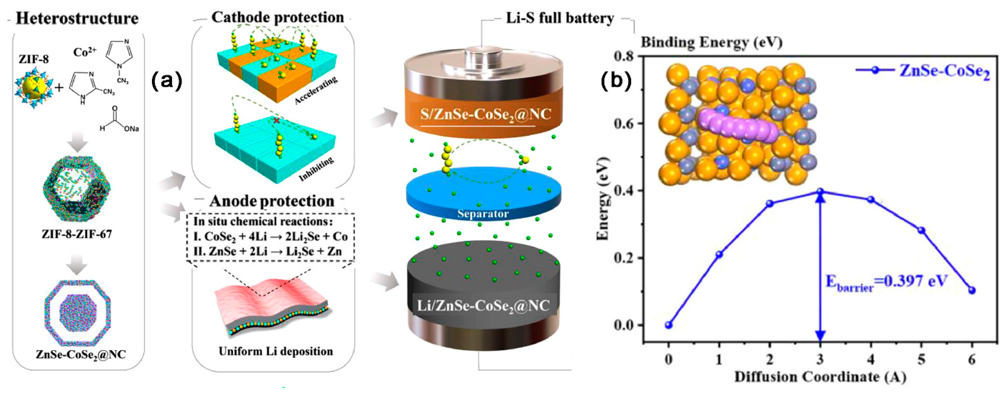
- Xu, J.; Xu, L.; Zhang, Z.; Sun, B.; Jin, Y.; Jin, Q.; Liu, H.; Wang, G. Heterostructure ZnSe-CoSe2 embedded with yolk-shell conductive dodecahedral as Two-in-one hosts for cathode and anode protection of Lithium–Sulfur full batteries. Energy Storage Mater. 2022, 47, 223–234. [Google Scholar] [CrossRef]
- Yang, S.; Xiao, R.; Hu, T.; Fan, X.; Xu, R.; Sun, Z.; Zhong, B.; Guo, X.; Li, F. Ni2P electrocatalysts decorated hollow carbon spheres as bi-functional mediator against shuttle effect and Li dendrite for Li-S batteries. Nano Energy 2021, 90, 106584. [Google Scholar] [CrossRef]
- Zhu, K.; Xue, P.; Cheng, G.; Wang, M.; Wang, H.; Bao, C.; Zhang, K.; Li, Q.; Sun, J.; Guo, S.; et al. Thermo-managing and flame-retardant scaffolds suppressing dendritic growth and polysulfide shuttling toward high-safety lithium–sulfur batteries. Energy Storage Mater. 2021, 43, 130–142. [Google Scholar] [CrossRef]
- Available online: www.sipa.columbia.edu (accessed on 1 January 2023).
- Zhao, M.; Li, B.Q.; Zhang, X.Q.; Huang, J.Q.; Zhang, Q. A Perspective toward Practical Lithium-Sulfur Batteries. ACS Cent. Sci. 2020, 6, 1095–1104. [Google Scholar] [CrossRef] [PubMed]


| Materials | SSA (m2 g−1) | Mesoporous Diameter (nm) | TPV (cm3 g−1) | S Content (wt%) | S Loading (mg cm−2) | Initial DSC (mAh g−1) | Cycling Performance (mAh g−1) | CDR (%) | Rate Performance (mAh g−1) | Reference |
|---|---|---|---|---|---|---|---|---|---|---|
| MHCS/S | 1875 | ~3.6 | 4.75 | 90.4 | 4.1 | 780/0.5 C | 432/0.5 C 1100 cycles | 0.054 | 476/2 C | [93] |
| rNGO/S | - | - | - | 70 | 1.2 | 1186/0.1 C | 837/0.1 C 200 cycles | 0.147 | 997/1 C | [97] |
| HPC-N2 | 965 | 3.7 | - | 60 | 3 | 972/0.1 C | 794/0.1 C 50 cycles | 0.366 | - | [96] |
| N-PC@uCo/S | 1185.36 | 10–50 | 0.98 | 76 | 1.8 | 912/1 C | 780/1 C 500 cycles | 0.028 | 600/5 C | [118] |
| BCN@HCS/S | 1057.9 | 2–4 | 0.72 | 70 | 4 | 1083/0.2 C | 1041/0.2 C 50 cycles | 0.038 | 670/3 C | [119] |
| NOMCs/S | 1021 | 3.76 | 0.99 | 60.5 | 1.2–1.5 | 638.3/0.5 C | 478.73/0.2 C 100 cycles | 0.25 | 472.2/1 C | [120] |
| BCP/S-6 | 2032.2 | 2–4 | 1.03 | 80 | 1.5 | 1385/0.1 C | 925/0.1 C 100 cycles | 0.29 | 462/2 C | [94] |
| S-OMC-100S-2 | 1011.5 | 4.0 | 1.18 | 41 | 1 | 517/0.1 C | - | - | - | [95] |
| HMCS/S@GO | 580 | 5.7 | - | 58.9 | - | 1054/0.5 C | 635/0.5 C 100 cycles | 0.398 | 626/2 C | [121] |
| NGLCNTs-850/S | 142 | 2–45 | - | 71 | 1.0–1.5 | 1199.4/0.3 C | 811/0.3 C 300 cycles | 0.159 | 613/3 C | [98] |
| FBC/S | 338.03 | 2.5 | - | 73.50 | 1.2 | 1145.9/0.1 C | 1099.99/0.1 C 100 cycles | 0.119 | 925.6/0.5 C | [122] |
| MPC/S | 368.5 | 6 | 0.56 | 11.7 | - | 1584.56/250 mA g−1 | 804.94/250 mA g−1 30 cycles | - | - | [91] |
| CMK-3 | 1976 | 3.33 | 2.1 | 70 | 1.82 | 1320/168 mA g−1 | - | - | - | [35] |
| Ni-NC(p)/S | 428.8 | 13 | 1.1 | 73.1 | 1.35–1.60 | 966.6/0.5 C | 1600/0.1 C 1600 cycles | 0.078 | 706.27/2 C | [48] |
| Co/PNC/S | 588.0 | ~5 | - | 59.66 | 1.5 | 1105.4/0.5 C | 746.7/0.5 C 100 cycles | 0.324 | 540.6/1 C | [99] |
| CFs/S | 156.8 | 9.8–14.7 | - | 70 | 3.69–3.71 | 855.6/135 mA g−1 | 586.5/135 mA g−1 120 cycles | 0.262 | 667.6/270 mA g−1 | [100] |
| SC-Co/S | 831 | 3–7 | 1.04 | 63 | 1.2 | 1130/0.5 C | 837/0.5 C 300 cycles | 0.086 | - | [45] |
| Fe-N-C/S-MCF | 1267 | 31 | 3.5 | 87.9 | 2.5 | 1631/0.5 C | 1280/0.5 C 100 cycles | 0.215 | 798/5 C | [123] |
| NMC-Al2O3/S | 1485 | 12 | 2.25 | 73.5 | 2.0 | 902/0.5 C | 685/0.5 C 1000 cycles | 0.023 | 755/2 C | [101] |
| SMC/S | 365.45 | 50 | 0.473 | 80 | 0.8~1.1 | 969.7/0.2 C | 625.5/0.2 C 400 cycles | 0.088 | 488.9/3 C | [102] |
| MnO-800/S | 300.9 | 18 | 0.57 | 62 | 1.8 | 1535.9/0.2 A g−1 | 989.9/0.2 A g−1 400 cycles | 0.088 | 808/4 A g−1 | [103] |
| NMC/La2O3/S | 731 | - | 2.6 | 60 | 1.67 | 1043/1 C | 799/1 C 100 cycles | 0.234 | 475/5 C | [124] |
| GP/CNT/LNO-V-S | 5 | - | 0.065 | - | 4.4 | 1007/0.2 C | 962/0.2 C 100 cycles | 0.045 | 844/1 C | [125] |
| S@C@MnO2/S | 1087.1 | 5 | 1.96 | 58.2 | 3 | 983/1 C | 550/1 C 500 cycles | 0.088 | 465/5 C | [126] |
| MnO2@HCB/S | 257 | 2–10 | 0.52 | 67.9 | 0.7–1 | 503/3 A g−1 | - | - | 496/4 A g−1 | [127] |
| SiOx-coated CMK-3/S | - | 3.5 | - | 1.2 | 718/0.1 C | 592.3/0.1 C 60 cycles | 0.292 | 897.4/1 C | [128] | |
| MCS-SiO2/MXene/S | 315.436 | 3.442 | 0.073 | 68 | 3.2 | 755.1/1 C | 537.6/1 C 500 cycles | 0.046 | 575.9/2 C | [129] |
| C-S-TiO2 | - | - | - | 53 | - | 1128/0.2 C | 608/0.2 C 120 cycles | 0.384 | 650/5 C | [130] |
| TiN-O-OMC/S | 355.9 | 3.5 | 0.95 | 75 | 1.4 | 790/0.2 C | 634/0.2 C 120 cycles | 0.16 | 550/2 C | [131] |
| KC/S-60 | 2000 | 4.2–18 | 3 | 72 | 1.5 | 1115/0.1 C | 820/0.1 C 120 cycles | 0.33 | - | [132] |
| TiO2/G/NPCFs/S | 341.5 | 3.6 | 0.309 | 55 | 1.2 | 987/1 C | 618/1 C 500 cycles | 0.074 | 668/5 C | [133] |
| RuO2-MPC-HS/S | 343 | 0.7–12.5 | 1.69 | 70 | - | 859/0.2 C | - | 0.052 | 665/0.5 C | [134] |
| ZCO-QDs@HCS/S | 782.50 | 5.0–9.5 | - | 70 | 1.3 | 1009.3/1 C | 675.2/1 C 400 cycles | 0.083 | 725.1/3 C | [135] |
| MCM/Nb2O5/S | 948 | 10 | 2.6 | 60 | 1.5 | 1289/0.5 C | 928.08/0.5 C 200 cycles | 0.14 | 640/5 C | [136] |
| OMCNS | 386.7 | 15–20 | 1.05 | 70 | 1–1.2 | 840 | 505.7/0.5 C 500 cycles | 0.081 | 580.6/2 C | [137] |
| HPC@TOH/S | 132.99 | - | - | 73.8 | - | 918.05/1 C | 697.72/1 C 400 cycles | 0.06 | 770.61/2 C | [104] |
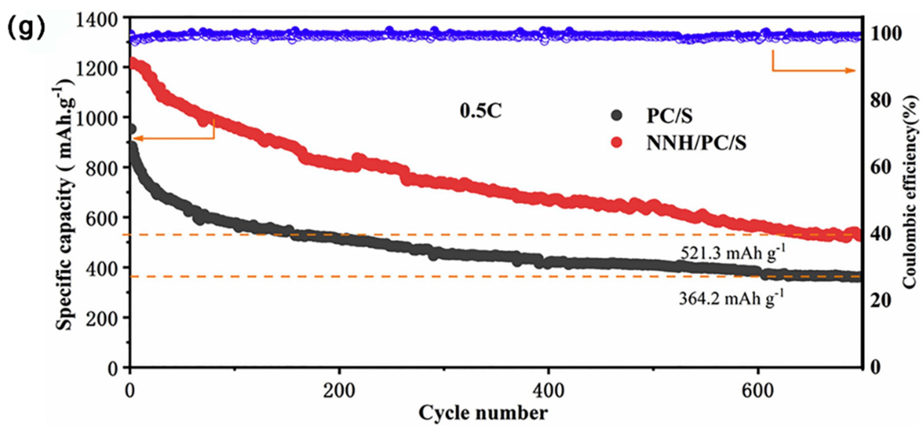
| NNH/PC/S | 2615 | 1–50 | - | 53.07 | 1.56 | 1203.5/0.5 C | 521.3/0.5 C 700 cycles | 0.081 | 583.9/5 C | [105] |
| Co9S8-NSHPC/S | 521.42 | 2–30 | - | 75 | 1.2 | 918/0.2 C | 867/0.2 C 200 cycles | 0.028 | 607/2 C | [106] |
| MoS2−X/HMC/S | 146.6 | - | 1.31 | 60 | 1.2 | 1077/0.2 C | 754/0.2 C 100 cycles | 0.3 | 528.3/5 C | [107] |
| C@MoS2/S | 455.9 | 3–4 | 0.48 | 80 | 1.3 | 752.5/2 C | 500/2 C 1000 cycles | 0.03 | 554.2/5 C | [108] |
| NMCS@MoS2/S | 323.5 | 13.02 | 1.14 | 70 | 1.2 | 847/1 C | 813/1 C 500 cycles | 0.08 | - | [138] |
| C-HS@NiS | 59 | - | - | 72 | 2.3 | 723.2/0.5 C | 695/0.5 C 300 cycles | 0.013 | 674/2 C | [109] |
| MoS2/CNT/S | 180.2 | - | 0.9 | 60 | 2.6 | 1470/0.2 C | 855.5/0.2 C 50 cycles | 0.83 | 1254/5 C | [139] |
| MHCS@MoS2/S | 742 | 40 | 1.026 | 72.1 | 1.5 | 980.93/1 C | 735.7/1 C 500 cycles | 0.05 | 886.0/2 C | [140] |
| RF-TiN/S | 900 | 42 | 4.12 | 70 | 1.5 | 924/1 C | 700/1 C 800 cycles | 0.04 | 690/5 C | [110] |
| VN-H-C/S | 316.42 | 5–20 | - | 74 | 1.5 | 856.5/1 C | 602.5/1 C 500 cycles | 0.059 | 789/2 C | [111] |
| C@TiN/S | 277 | - | - | 71 | 1.1 | 457.58/3 C | 453/3 C 300 cycles | 0.0033 | 373/5 C | [112] |
| PCF/VN/S | - | - | - | 60.1 | 8.1 | 1310.8/0.1 C | 1052.5/0.1 C 250 cycles | 0.07 | 591.6/5 C | [141] |
| TSC/NbC/S | 555 | 30–50 | - | 66.02 | 2 | 1153.63/0.1 C | 937.9/0.1 C 500 cycles | 0.037 | 499/5 C | [113] |
| MHCS@Mo2 C/C/S | 813.6 | 3–9 | 1.17 | 71.8 | 1.2 | 1316.8/0.1 C | 880.1/0.1 C 100 cycles | 0.33 | 678.8/2 C | [114] |
| HCN@NbC/S | 1348 | 8 | 3.13 | 80 | 1.5 | 953/1 C | 595/1 C 800 cycles | 0.05 | 752/5 C | [115] |
| TiC/C/S | 760 | - | 0.799 | 74 | 1.1 | 821/0.2 A g−1 | 602/0.2 A g−1 200 cycles | 0.133 | 438/2 A g−1 | [142] |
| CoP@3DSC/S | 867.78 | 5–15 | - | 73.3 | 1.17 | 1117.37/0.5 C | 740.56/0.5 C 600 cycles | 0.056 | 820.72/2 C | [116] |
| PCM/FeP/S | 500 | - | 0.9 | 75 | 2 | 1231/0.5 C | 910.7/0.5 C 500 cycles | 0.05 | 655/3 C | [117] |
| Co/CoP@NC/S | 20 | - | - | 75.8 | 2.5 | 848.54/1 C | 638/1 C 1000 cycles | 0.033 | 472/20C | [143] |
| CoFeP@CN/S | 186 | - | 0.85 | 70 | 4.1 | 683.39/1 C | 608/1 C 400 cycles | 0.031 | 630/5 C | [144] |
Disclaimer/Publisher’s Note: The statements, opinions and data contained in all publications are solely those of the individual author(s) and contributor(s) and not of MDPI and/or the editor(s). MDPI and/or the editor(s) disclaim responsibility for any injury to people or property resulting from any ideas, methods, instructions or products referred to in the content. |
© 2023 by the authors. Licensee MDPI, Basel, Switzerland. This article is an open access article distributed under the terms and conditions of the Creative Commons Attribution (CC BY) license (https://creativecommons.org/licenses/by/4.0/).
Share and Cite
Wang, F.; Han, Y.; Feng, X.; Xu, R.; Li, A.; Wang, T.; Deng, M.; Tong, C.; Li, J.; Wei, Z. Mesoporous Carbon-Based Materials for Enhancing the Performance of Lithium-Sulfur Batteries. Int. J. Mol. Sci. 2023, 24, 7291. https://doi.org/10.3390/ijms24087291
Wang F, Han Y, Feng X, Xu R, Li A, Wang T, Deng M, Tong C, Li J, Wei Z. Mesoporous Carbon-Based Materials for Enhancing the Performance of Lithium-Sulfur Batteries. International Journal of Molecular Sciences. 2023; 24(8):7291. https://doi.org/10.3390/ijms24087291
Chicago/Turabian StyleWang, Fangzheng, Yuying Han, Xin Feng, Rui Xu, Ang Li, Tao Wang, Mingming Deng, Cheng Tong, Jing Li, and Zidong Wei. 2023. "Mesoporous Carbon-Based Materials for Enhancing the Performance of Lithium-Sulfur Batteries" International Journal of Molecular Sciences 24, no. 8: 7291. https://doi.org/10.3390/ijms24087291
APA StyleWang, F., Han, Y., Feng, X., Xu, R., Li, A., Wang, T., Deng, M., Tong, C., Li, J., & Wei, Z. (2023). Mesoporous Carbon-Based Materials for Enhancing the Performance of Lithium-Sulfur Batteries. International Journal of Molecular Sciences, 24(8), 7291. https://doi.org/10.3390/ijms24087291