
CuxCo1-xFe2O4 (x = 0.33, 0.67, 1) Spinel Ferrite Nanoparticles Based Thermoplastic Polyurethane Nanocomposites with Reduced Graphene Oxide for Highly Efficient Electromagnetic Interference Shielding

 ,
,  ,
,  ,
,  ,
,  ,
,  , , ,
, , ,  ,
,  , and
, and
Abstract
:1. Introduction
2. Results and Discussion
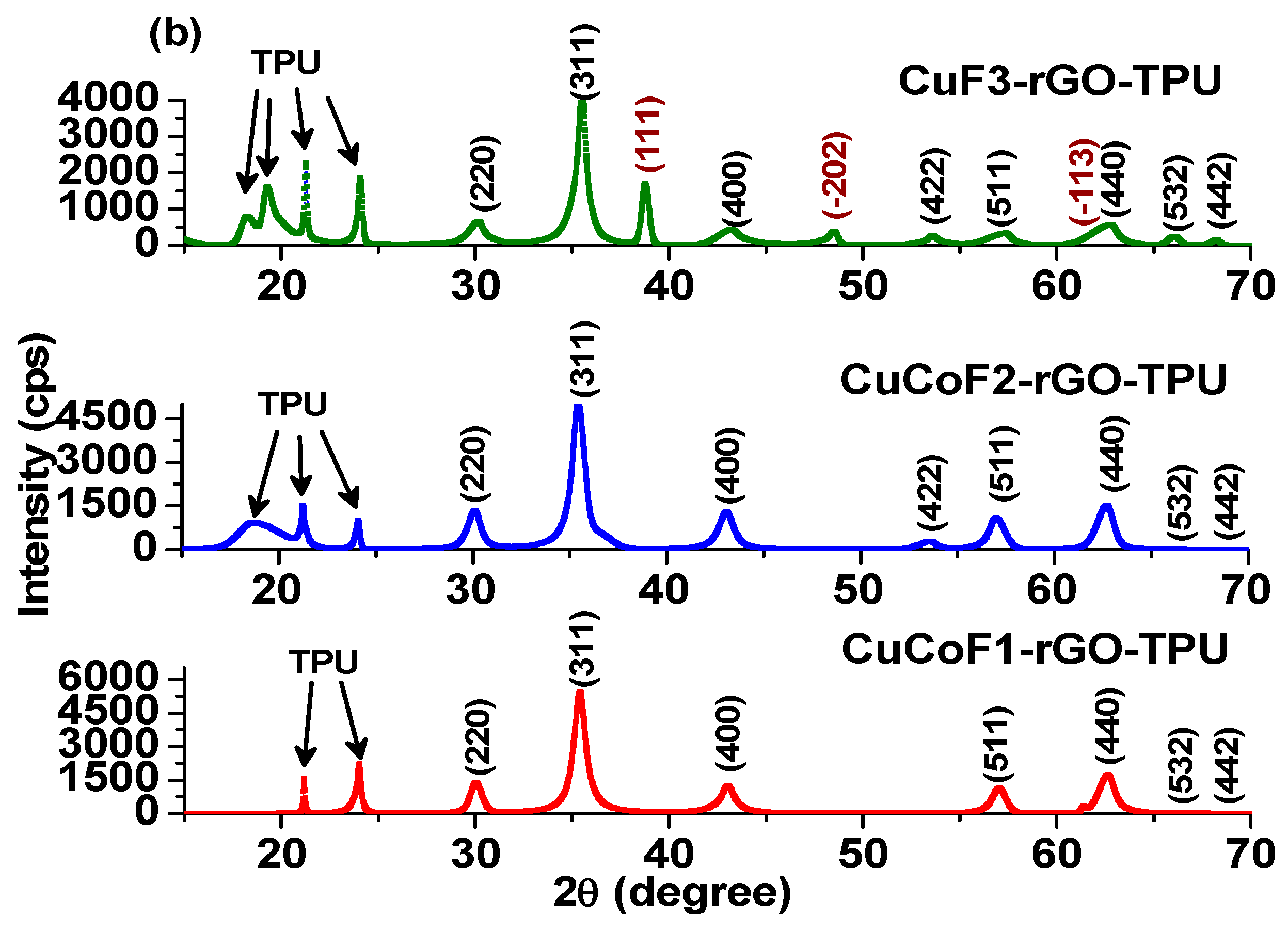
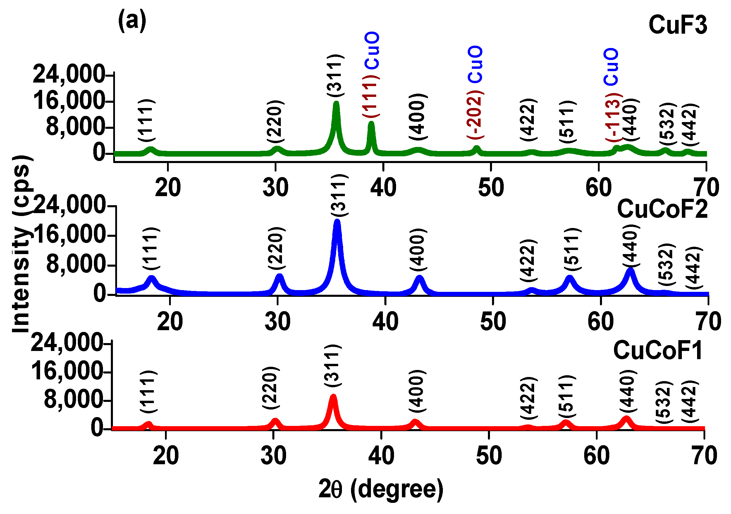
2.1. XRD Study
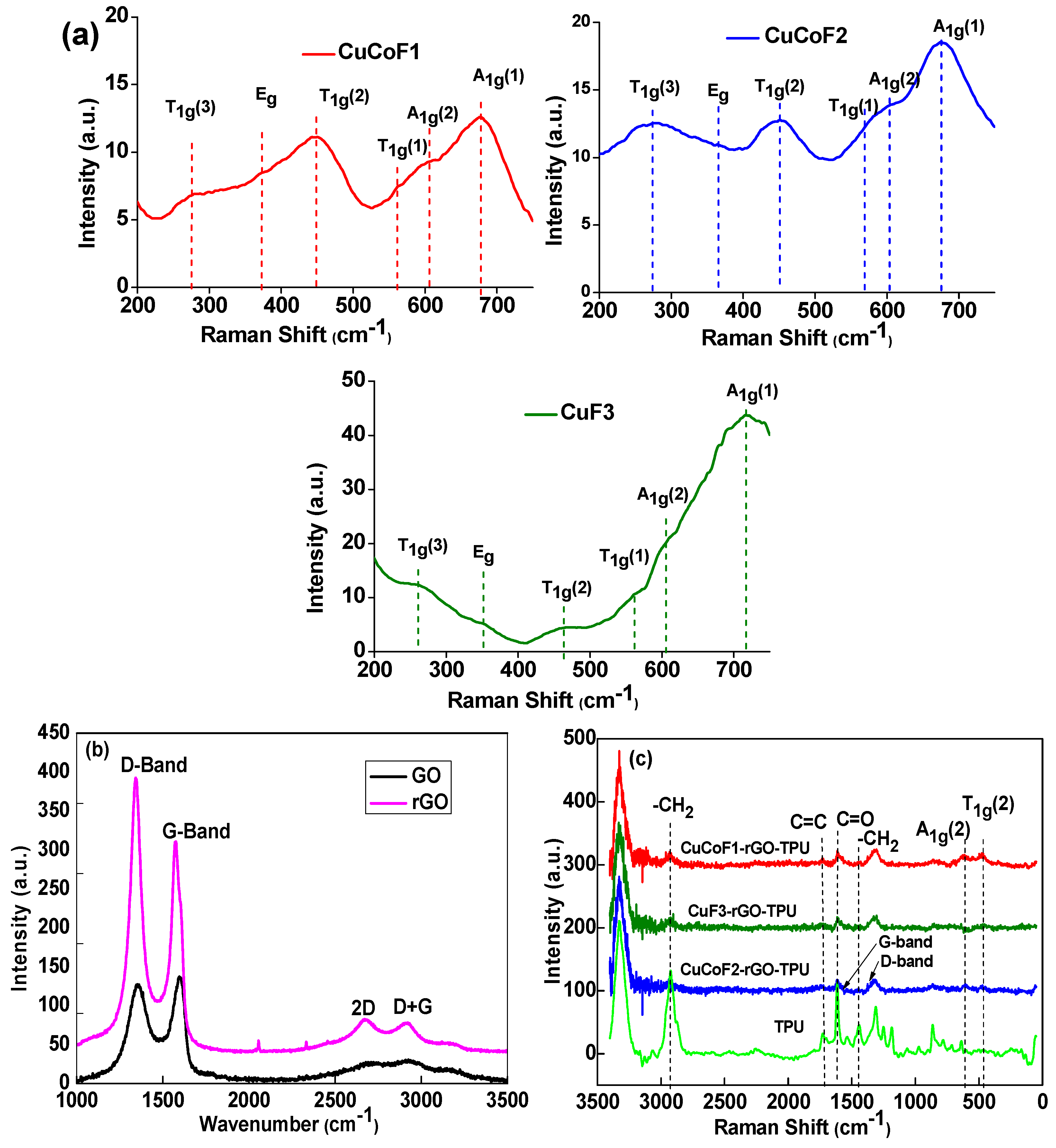
2.2. Raman Study
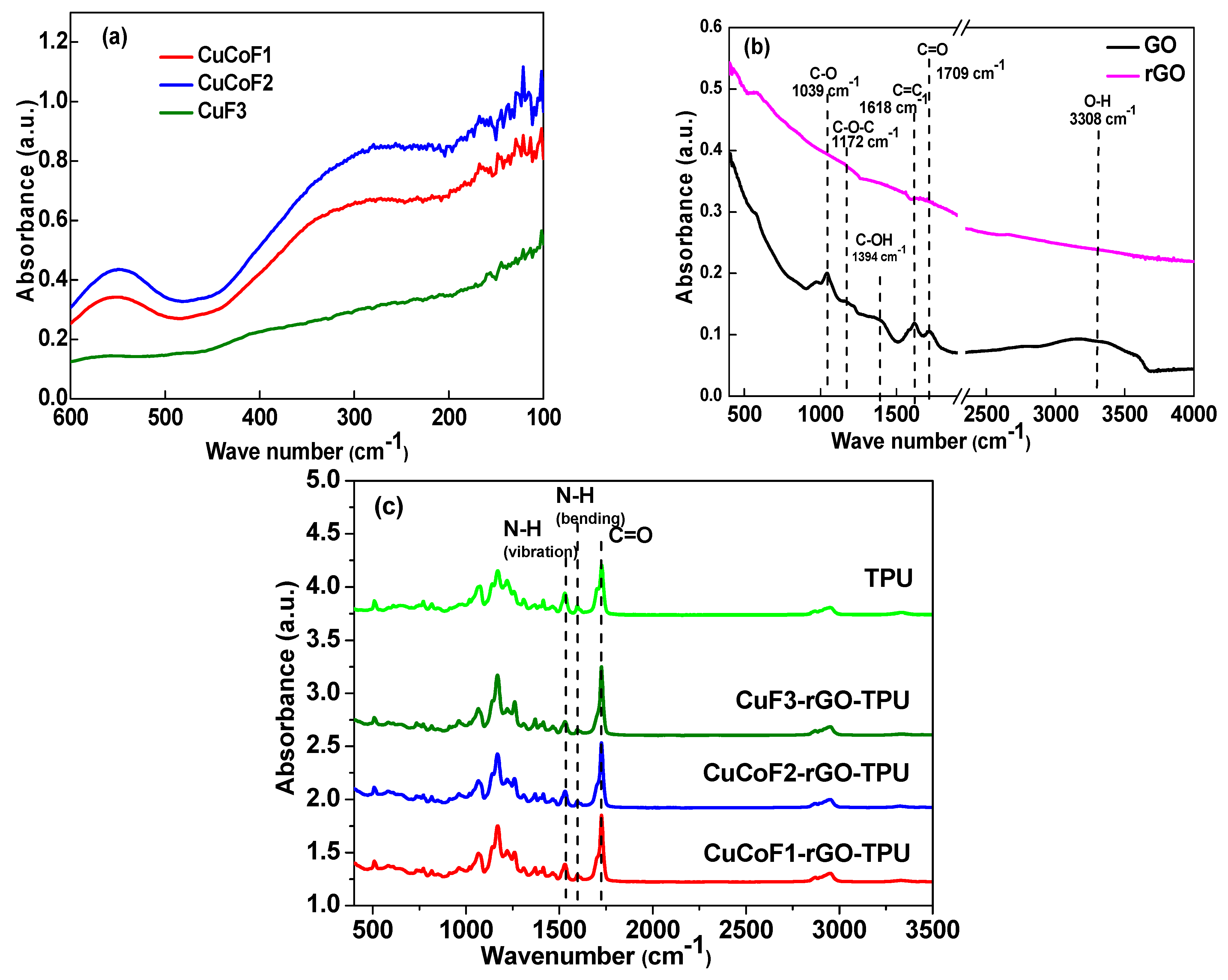
2.3. Fourier Transform Infra-Red Spectroscopy (FTIR) Analysis
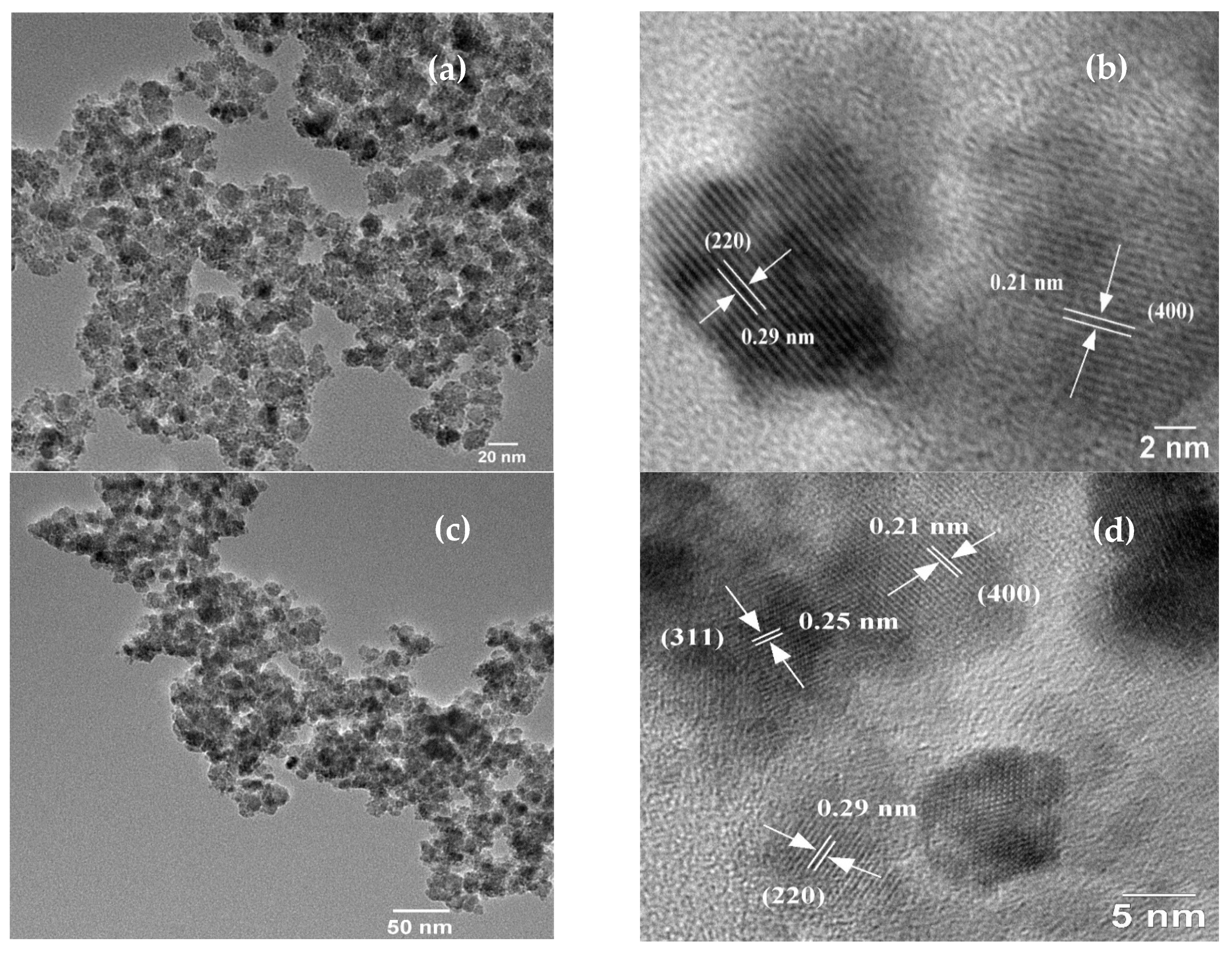
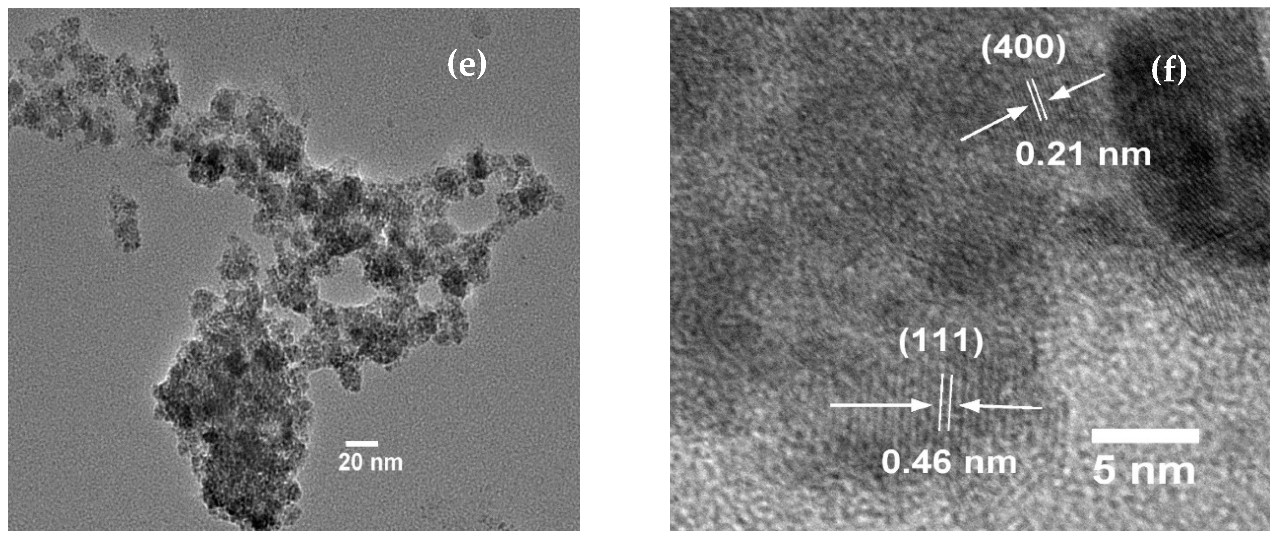
2.4. TEM and HRTEM Analysis of Nanoparticles
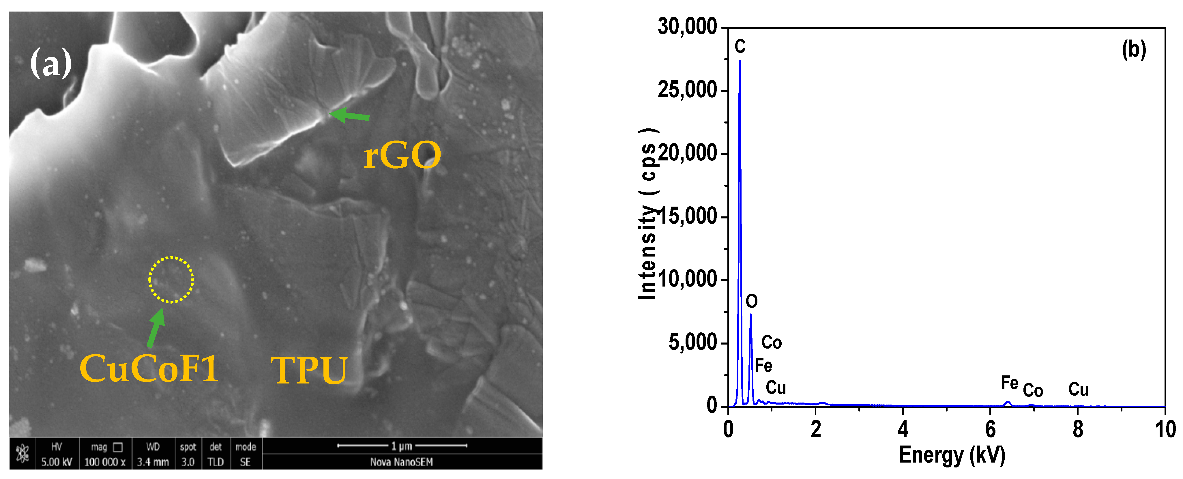
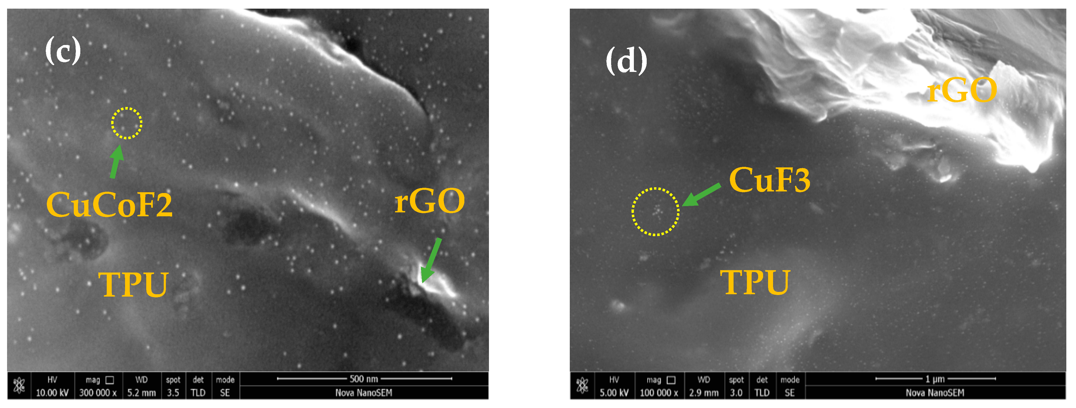
2.5. FE-SEM and EDX Study of Nanocomposites
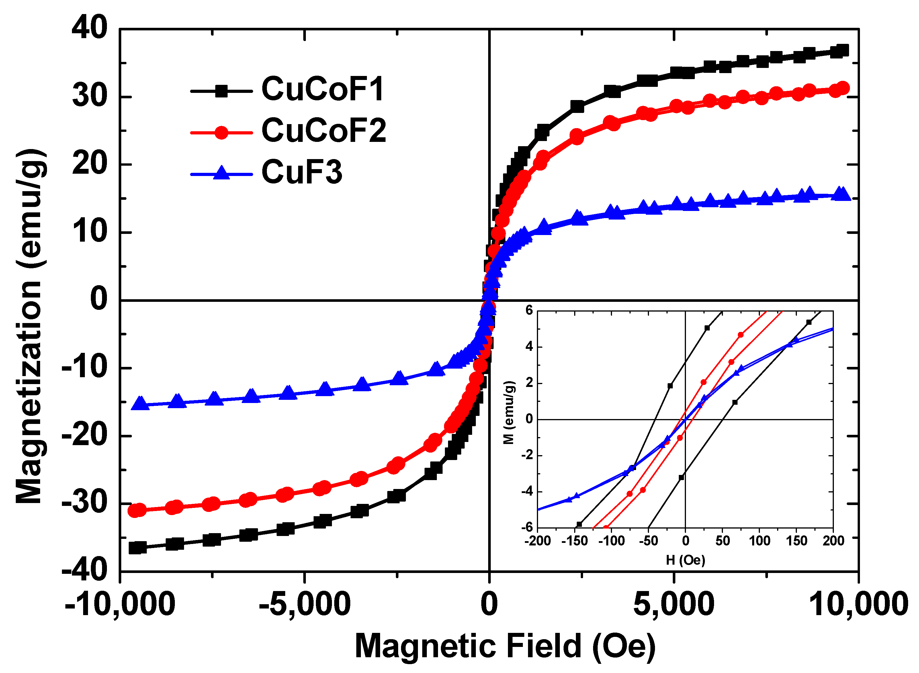
2.6. Magnetic Property
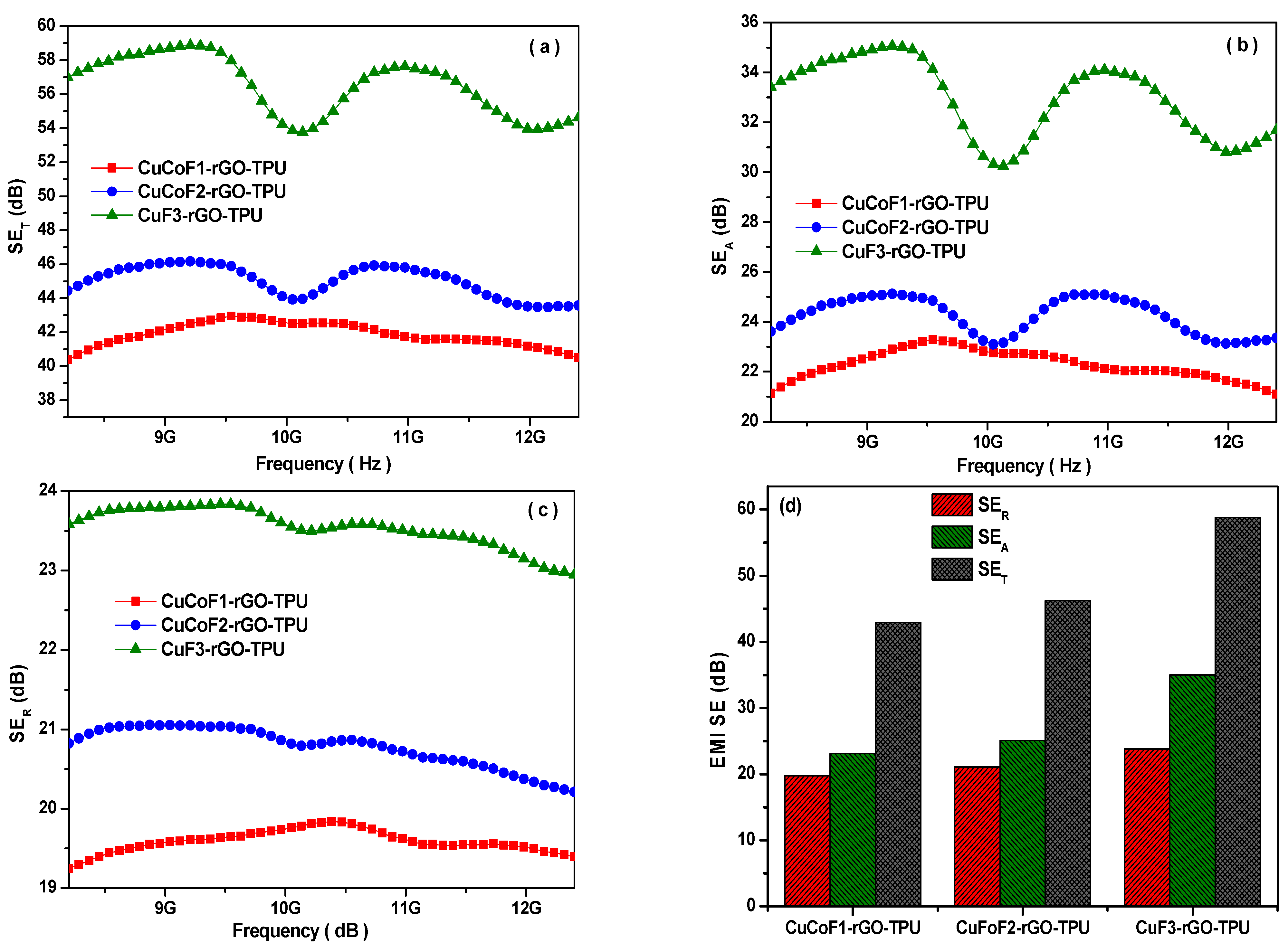
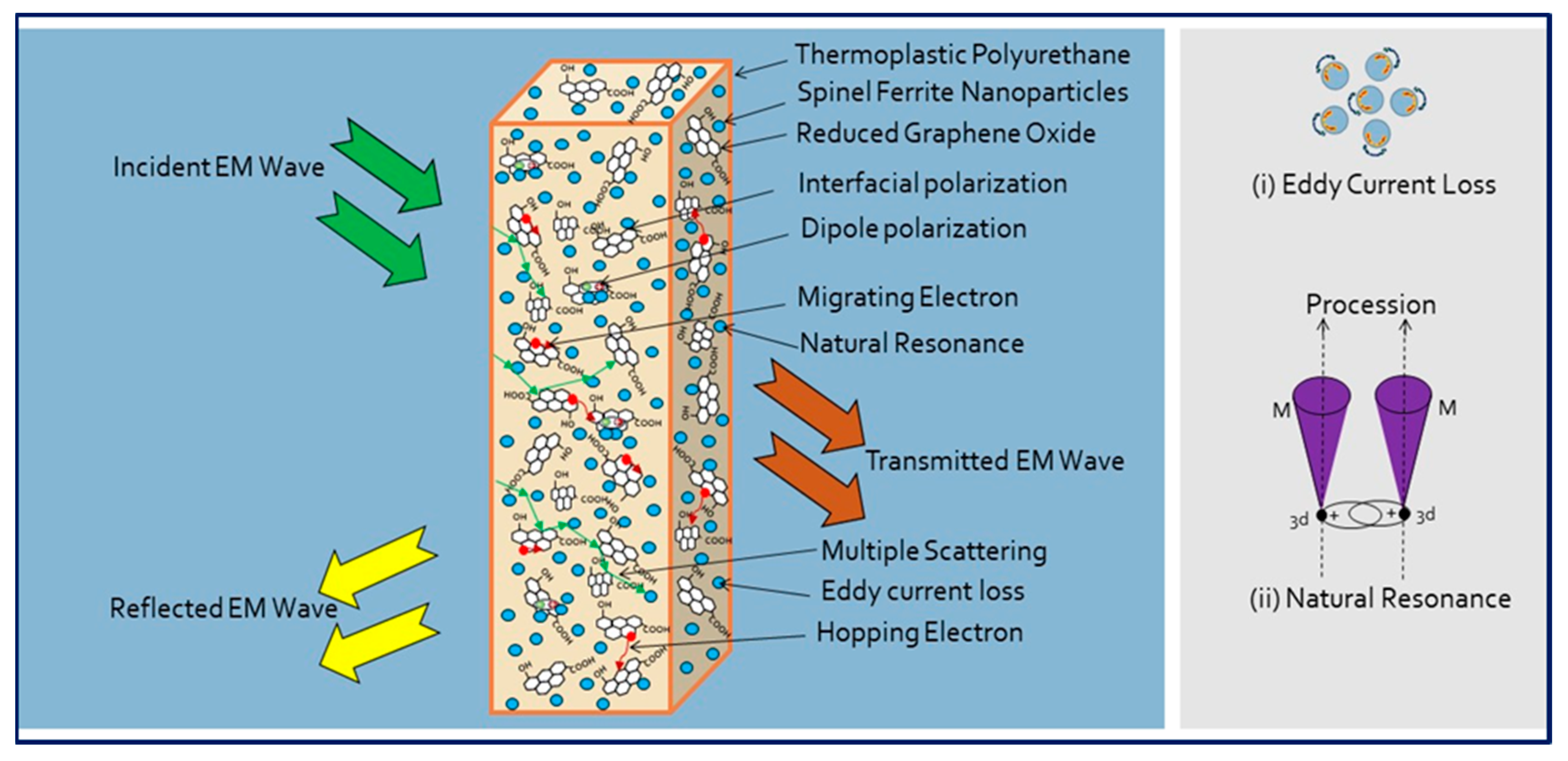
2.7. Electromagnetic Interference Shielding
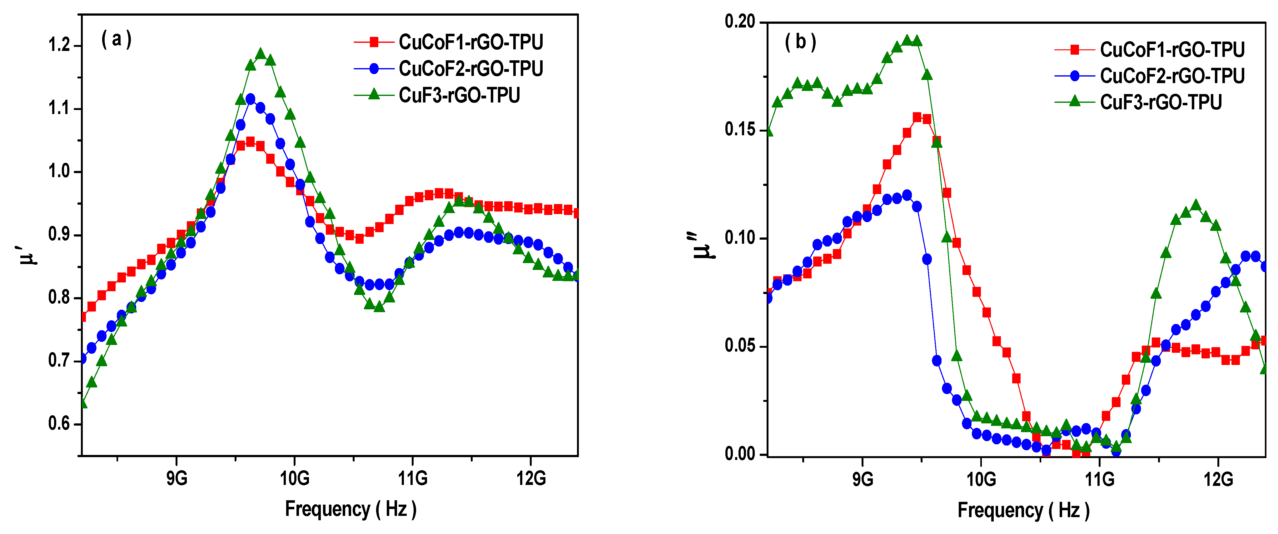
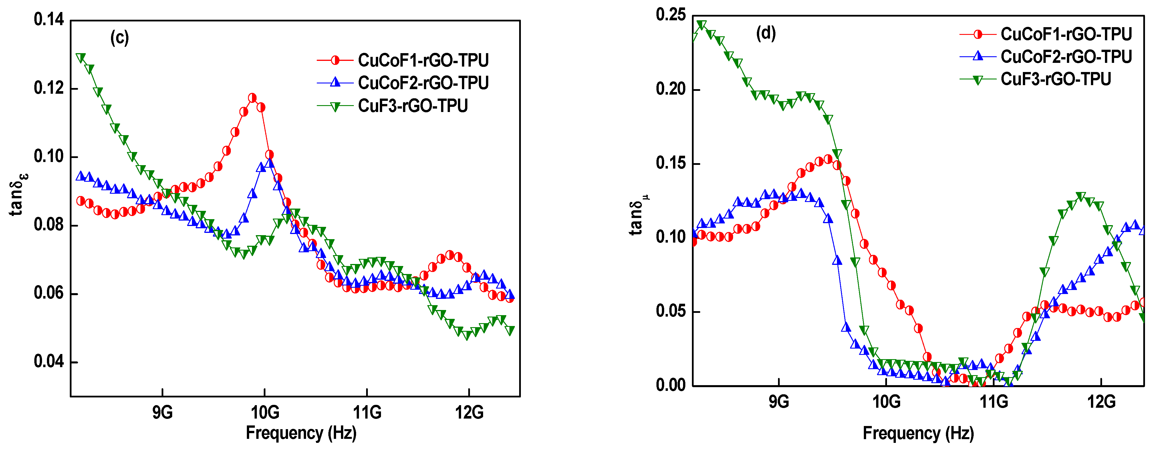
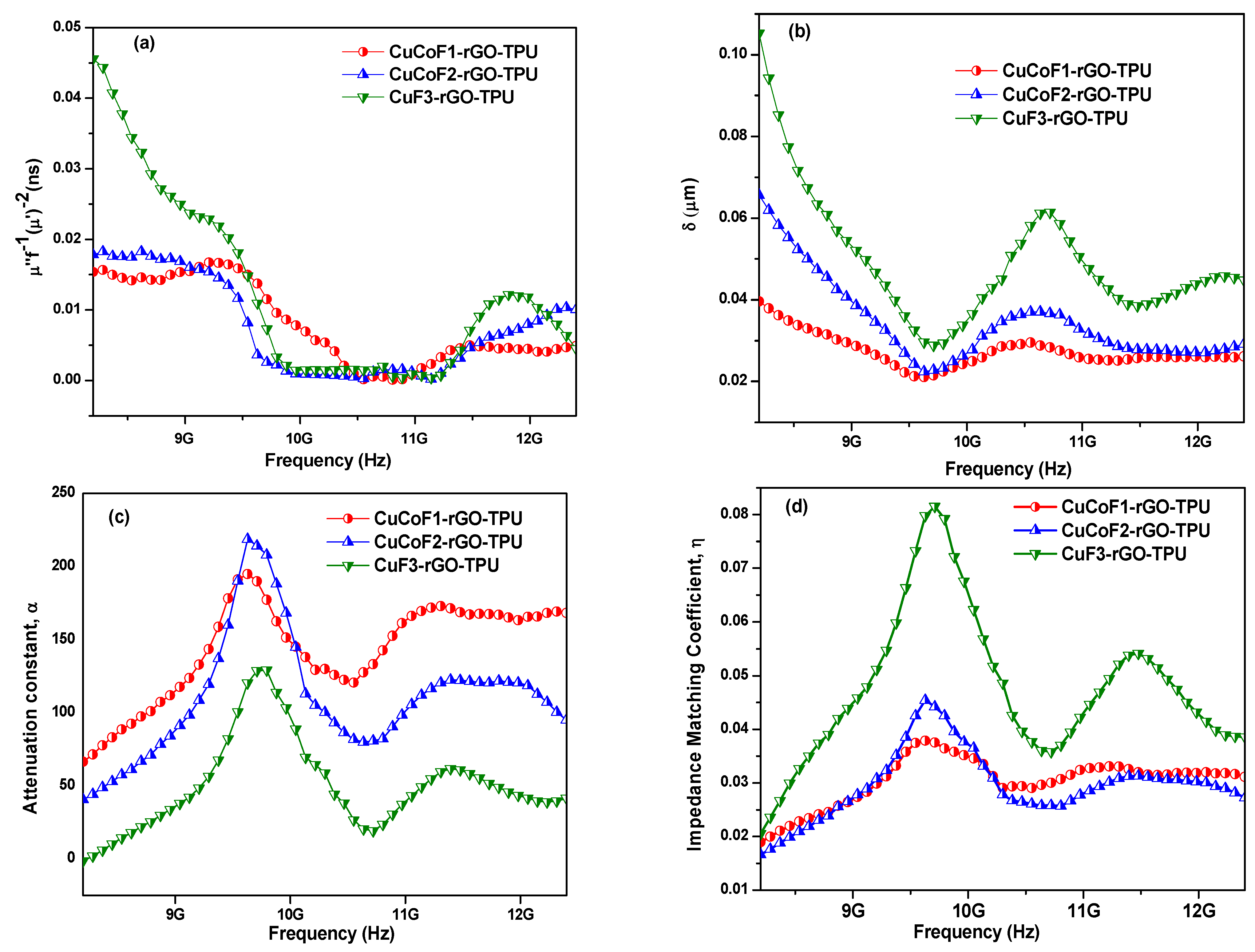
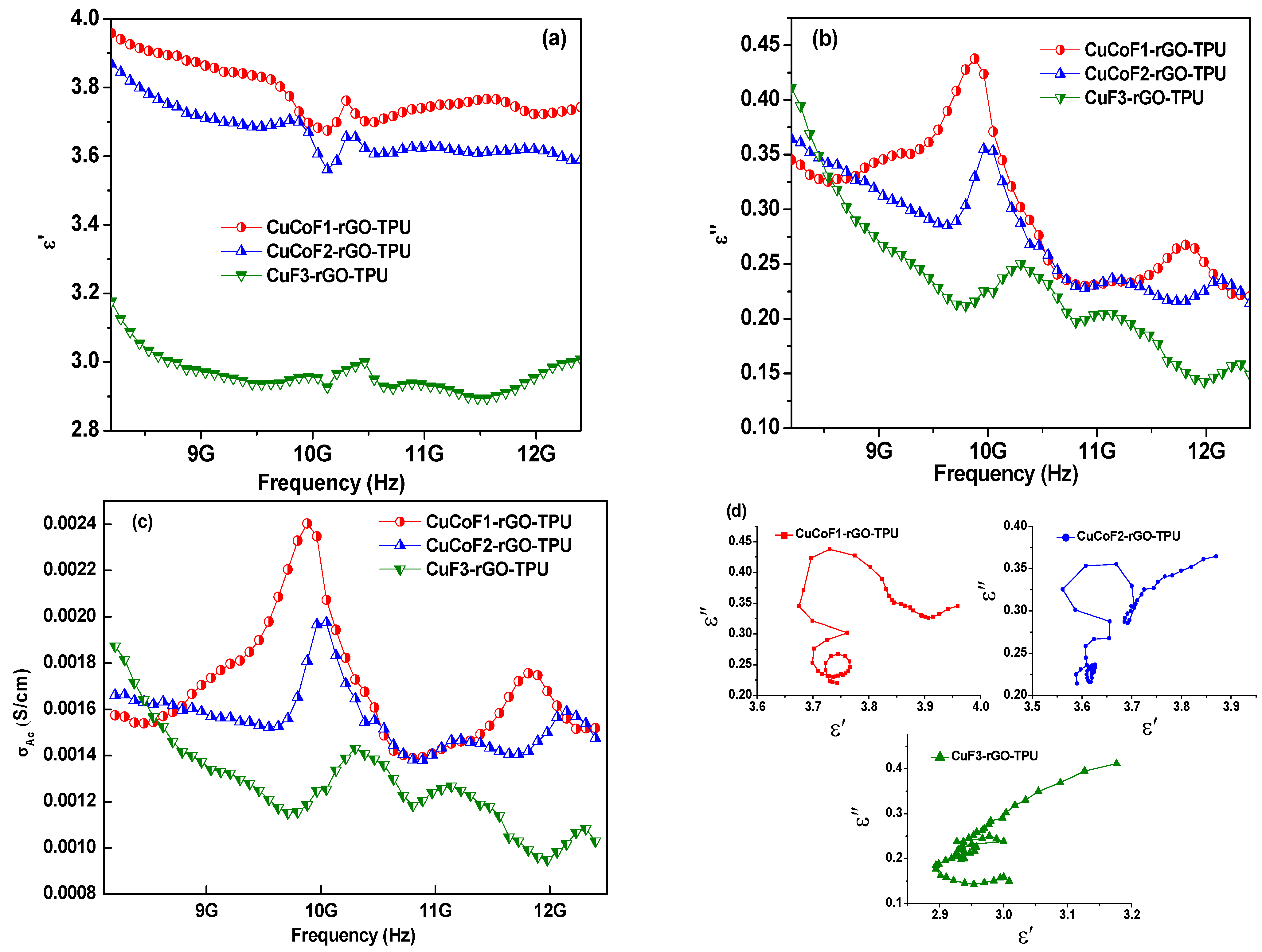
2.8. Electromagnetic Parameters
3. Materials and Methods
3.1. Chemicals
3.2. Synthesis of CuxCo1-xFe2O4 (x = 0.33. 0.67, 1) Spinel Ferrite Nanoparticles
3.3. Synthesis of Graphene Oxide
3.4. Synthesis of Reduced Graphene Oxide
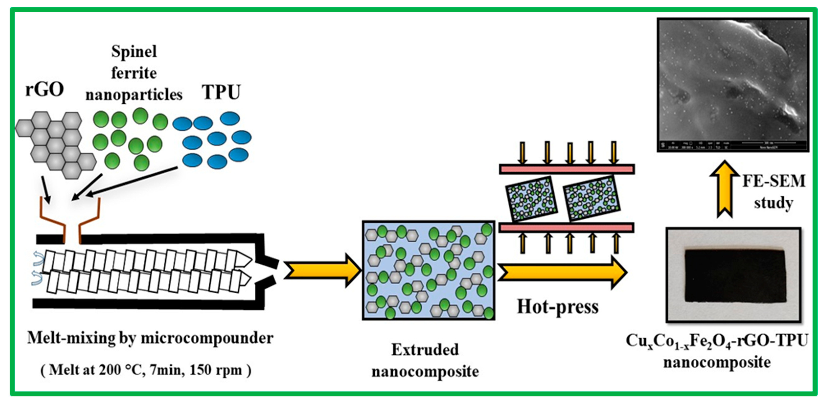
3.5. Preparation of Nanocomposites
4. Conclusions
Author Contributions
Funding
Institutional Review Board Statement
Informed Consent Statement
Data Availability Statement
Acknowledgments
Conflicts of Interest
References
- Yadav, R.S.; Kuřitka, I.; Vilčáková, J. Advanced Spinel Ferrite Nanocomposites for Electromagnetic Interference Shielding Applications; Elsevier: Cambridge, MA, USA, 2020; ISBN 978-0-12-821291-2. [Google Scholar]
- Bhawal, P.; Ganguly, S.; Das, T.K.; Mondal, S.; Choudhury, S.; Das, N.C. Superior Electromagnetic Interference Shielding Effectiveness and Electro-Mechanical Properties of EMA-IRGO Nanocomposites through the in-Situ Reduction of GO from Melt Blended EMA-GO Composites. Compos. Part B Eng. 2018, 134, 46–60. [Google Scholar] [CrossRef]
- Kumaran, R.; kumar, S.D.; Balasubramanian, N.; Alagar, M.; Subramanian, V.; Dinakaran, K. Enhanced Electromagnetic Interference Shielding in a Au–MWCNT Composite Nanostructure Dispersed PVDF Thin Films. J. Phys. Chem. C 2016, 120, 13771–13778. [Google Scholar] [CrossRef]
- Ravindren, R.; Mondal, S.; Nath, K.; Das, N.C. Prediction of Electrical Conductivity, Double Percolation Limit and Electromagnetic Interference Shielding Effectiveness of Copper Nanowire Filled Flexible Polymer Blend Nanocomposites. Compos. Part B Eng. 2019, 164, 559–569. [Google Scholar] [CrossRef]
- Duan, H.; He, P.; Zhu, H.; Yang, Y.; Zhao, G.; Liu, Y. Constructing 3D Carbon-Metal Hybrid Conductive Network in Polymer for Ultra-Efficient Electromagnetic Interference Shielding. Compos. Part B Eng. 2021, 212, 108690. [Google Scholar] [CrossRef]
- Paun, C.; Obreja, C.; Comanescu, F.; Tucureanu, V.; Tutunaru, O.; Romanitan, C.; Ionescu, O.; Gavrila, D.E.; Paltanea, V.M.; Stoica, V.; et al. Studies on Structural MWCNT/Epoxy Nanocomposites for EMI Shielding Applications. IOP Conf. Ser. Mater. Sci. Eng. 2021, 1009, 012046. [Google Scholar] [CrossRef]
- Rani, P.; Ahamed, B.; Deshmukh, K. Dielectric and Electromagnetic Interference Shielding Properties of Zeolite 13X and Carbon Black Nanoparticles Based PVDF Nanocomposites. J. Appl. Polym. Sci. 2021, 138, 50107. [Google Scholar] [CrossRef]
- Gulzar, N.; Zubair, K.; Shakir, M.F.; Zahid, M.; Nawab, Y.; Rehan, Z.A. Effect on the EMI Shielding Properties of Cobalt Ferrites and Coal-Fly-Ash Based Polymer Nanocomposites. J. Supercond. Nov. Magn. 2020, 33, 3519–3524. [Google Scholar] [CrossRef]
- Valentini, M.; Piana, F.; Pionteck, J.; Lamastra, F.R.; Nanni, F. Electromagnetic Properties and Performance of Exfoliated Graphite (EG)—Thermoplastic Polyurethane (TPU) Nanocomposites at Microwaves. Compos. Sci. Technol. 2015, 114, 26–33. [Google Scholar] [CrossRef]
- Zahid, M.; Nawab, Y.; Gulzar, N.; Rehan, Z.A.; Shakir, M.F.; Afzal, A.; Abdul Rashid, I.; Tariq, A. Fabrication of reduced graphene oxide (RGO) and nanocomposite with thermoplastic polyurethane (TPU) for EMI shielding application. J. Mater. Sci. Mater. Electron. 2020, 31, 967–974. [Google Scholar] [CrossRef]
- Sobha, A.P.; Sreekala, P.S.; Narayanankutty, S.K. Electrical, Thermal, Mechanical and Electromagnetic Interference Shielding Properties of PANI/FMWCNT/TPU Composites. Prog. Org. Coat. 2017, 113, 168–174. [Google Scholar] [CrossRef]
- Yadav, R.S.; Anju; Jamatia, T.; Kuřitka, I.; Vilčáková, J.; Škoda, D.; Urbánek, P.; Machovský, M.; Masař, M.; Urbánek, M.; et al. Excellent, Lightweight and Flexible Electromagnetic Interference Shielding Nanocomposites Based on Polypropylene with MnFe2O4 Spinel Ferrite Nanoparticles and Reduced Graphene Oxide. Nanomaterials 2020, 10, 2481. [Google Scholar] [CrossRef]
- Kumar, A.; Singh, A.K.; Tomar, M.; Gupta, V.; Kumar, P.; Singh, K. Electromagnetic Interference Shielding Performance of Lightweight NiFe2O4/RGO Nanocomposite in X- Band Frequency Range. Ceram. Int. 2020, 46, 15473–15481. [Google Scholar] [CrossRef]
- Dey, C.C.; Mahapatra, A.S.; Sadhukhan, S.; Chakrabarti, P.K. Electromagnetic Shielding Performance of Co0.5Zn0.4Cu0.1Fe2O4-GO/Paraffin Wax Hybrid Nanocomposite through Magnetic Energy Morphing Prepared by Facile Synthesis Method. Mater. Today Commun. 2021, 27, 102190. [Google Scholar] [CrossRef]
- Ismail, M.M.; Rafeeq, S.N.; Sulaiman, J.M.A.; Mandal, A. Electromagnetic Interference Shielding and Microwave Absorption Properties of Cobalt Ferrite CoFe2O4/Polyaniline Composite. Appl. Phys. A 2018, 124, 380. [Google Scholar] [CrossRef]
- Chitra, P.; Kumar, E.R.; Pushpagiri, T.; Steephen, A. Size and Phase Purity–Dependent Microstructural and Magnetic Properties of Spinel Ferrite Nanoparticles. J. Supercond. Nov. Magn. 2021, 34, 1239–1244. [Google Scholar] [CrossRef]
- Thanh, N.K.; Loan, T.T.; Anh, L.N.; Duong, N.P.; Soontaranon, S.; Thammajak, N.; Hien, T.D. Cation Distribution in CuFe2O4 Nanoparticles: Effects of Ni Doping on Magnetic Properties. J. Appl. Phys. 2016, 120, 142115. [Google Scholar] [CrossRef]
- Zhu, G.; Xu, H.; Xiao, Y.; Liu, Y.; Yuan, A.; Shen, X. Facile Fabrication and Enhanced Sensing Properties of Hierarchically Porous CuO Architectures. ACS Appl. Mater. Interfaces 2012, 4, 744–751. [Google Scholar] [CrossRef]
- Amulya, M.A.S.; Nagaswarupa, H.P.; Kumar, M.R.A.; Ravikumar, C.R.; Kusuma, K.B.; Prashantha, S.C. Evaluation of bifunctional applications of CuFe2O4 nanoparticles synthesized by a sonochemical method. J. Phys. Chem. Solids 2021, 148, 109756. [Google Scholar] [CrossRef]
- Gao, S.; Chen, X.; Pan, F.; Song, K.; Zhao, C.; Liu, L.; Liu, X.; Zhao, D. Efect of secondary phase on the electromagnetic shielding efectiveness of magnesium alloy. Sci. Rep. 2018, 8, 1625. [Google Scholar] [CrossRef] [PubMed]
- Song, L.; Duan, Y.; Cui, Y.; Huang, Z. Fe-Doped MnO2 Nanostructures for Attenuation−Impedance Balance-Boosted Microwave Absorption. ACS Appl. Nano Mater. 2022, 5, 2738. [Google Scholar] [CrossRef]
- Tedjieukeng, H.M.K.; Tsobnang, P.K.; Fomekong, R.L.; Etape, E.P.; Joy, P.A.; Delcorte, A.; Lambi, J.N. Structural Characterization and Magnetic Properties of Undoped and Copper-Doped Cobalt Ferrite Nanoparticles Prepared by the Octanoate Coprecipitation Route at Very Low Dopant Concentrations. RSC Adv. 2018, 8, 38621–38630. [Google Scholar] [CrossRef] [Green Version]
- Anugraha, A.; Lakshmi, V.K.; Kumar, G.S.; Raguram, T.; Rajni, K.S. Synthesis and Characterisation of Copper Substituted Cobalt Ferrite Nanoparticles by Sol-Gel Auto Combustion Route. IOP Conf. Ser. Mater. Sci. Eng. 2019, 577, 012059. [Google Scholar] [CrossRef]
- Jnaneshwara, D.M.; Avadhani, D.N.; Daruka Prasad, B.; Nagabhushana, H.; Nagabhushana, B.M.; Sharma, S.C.; Prashantha, S.C.; Shivakumara, C. Role of Cu2+ Ions Substitution in Magnetic and Conductivity Behavior of Nano-CoFe2O4. Spectrochim. Acta Part A Mol. Biomol. Spectrosc. 2014, 132, 256–262. [Google Scholar] [CrossRef] [PubMed]
- Mahalakshmi, S.; Jayasri, R.; Nithiyanatham, S.; Swetha, S.; Santhi, K. Magnetic Interactions and Dielectric Behaviour of Cobalt Ferrite and Barium Titanate Multiferroics Nanocomposites. Appl. Surf. Sci. 2019, 494, 51–56. [Google Scholar] [CrossRef]
- Chen, Y.; Pötschke, P.; Pionteck, J.; Voit, B.; Qi, H. Multifunctional Cellulose/RGO/Fe3O4 Composite Aerogels for Electromagnetic Interference Shielding. ACS Appl. Mater. Interfaces 2020, 12, 22088–22098. [Google Scholar] [CrossRef] [PubMed]
- Jing, X.; Mi, H.-Y.; Huang, H.-X.; Turng, L.-S. Shape Memory Thermoplastic Polyurethane (TPU)/Poly(ε-Caprolactone) (PCL) Blends as Self-Knotting Sutures. J. Mech. Behav. Biomed. Mater. 2016, 64, 94–103. [Google Scholar] [CrossRef]
- Beniwal, A. Sunny Novel TPU/Fe2O3 and TPU/Fe2O3/PPy Nanocomposites Synthesized Using Electrospun Nanofibers Investigated for Analyte Sensing Applications at Room Temperature. Sens. Actuators B Chem. 2020, 304, 127384. [Google Scholar] [CrossRef]
- Kumar, S.; Gupta, T.K.; Varadarajan, K.M. Strong, Stretchable and Ultrasensitive MWCNT/TPU Nanocomposites for Piezoresistive Strain Sensing. Compos. Part B Eng. 2019, 177, 107285. [Google Scholar] [CrossRef]
- Anju; Yadav, R.S.; Pötschke, P.; Pionteck, J.; Krause, B.; Kuřitka, I.; Vilcakova, J.; Skoda, D.; Urbánek, P.; Machovsky, M.; et al. High-Performance, Lightweight, and Flexible Thermoplastic Polyurethane Nanocomposites with Zn2+-Substituted CoFe2O4 Nanoparticles and Reduced Graphene Oxide as Shielding Materials against Electromagnetic Pollution. ACS Omega 2021, 6, 28098–28118. [Google Scholar] [CrossRef]
- Barick, A.K.; Tripathy, D.K. Preparation, characterization and properties of acid functionalized multi-walled carbon nanotube reinforced thermoplastic polyurethane nanocomposites. Mater. Sci. Eng. B 2011, 176, 1435–1447. [Google Scholar] [CrossRef]
- Chandramohan, P.; Srinivasan, M.P.; Velmurugan, S.; Narasimhan, S.V. Cation distribution and particle size effect on Raman spectrum of CoFe2O4. J. Solid State Chem. 2011, 184, 89–96. [Google Scholar] [CrossRef]
- Nandan, B.; Bhatnagar, M.C.; Kashyap, S.C. Cation Distribution in Nanocrystalline Cobalt Substituted Nickel Ferrites: X-ray Diffraction and Raman Spectroscopic Investigations. J. Phys. Chem. Solids 2019, 129, 298–306. [Google Scholar] [CrossRef]
- Sumalatha, M.; Shravan kumar Reddy, S.; Reddy, M.S.; Sripada, S.; Raja, M.M.; Reddy, C.G.; Reddy, P.Y.; Reddy, V.R. Raman and In-Field 57Fe Mössbauer Study of Cation Distribution in Ga Substituted Cobalt Ferrite (CoFe2-xGaxO4). J. Alloy. Compd. 2020, 837, 155478. [Google Scholar] [CrossRef]
- Hidayah, N.M.S.; Liu, W.-W.; Lai, C.-W.; Noriman, N.Z.; Khe, C.-S.; Hashim, U.; Lee, H.C. Comparison on Graphite, Graphene Oxide and Reduced Graphene Oxide: Synthesis and Characterization. AIP Conf. Proc. 2017, 1892, 150002. [Google Scholar] [CrossRef]
- Sadhukhan, S.; Ghosh, T.K.; Roy, I.; Rana, D.; Bhattacharyya, A.; Saha, R.; Chattopadhyay, S.; Khatua, S.; Acharya, K.; Chattopadhyay, D. Green Synthesis of Cadmium Oxide Decorated Reduced Graphene Oxide Nanocomposites and Its Electrical and Antibacterial Properties. Mater. Sci. Eng. C 2019, 99, 696–709. [Google Scholar] [CrossRef] [PubMed]
- Konios, D.; Stylianakis, M.M.; Stratakis, E.; Kymakis, E. Dispersion Behaviour of Graphene Oxide and Reduced Graphene Oxide. J. Colloid Interface Sci. 2014, 430, 108–112. [Google Scholar] [CrossRef] [PubMed]
- Gnanaseelan, M.; Samanta, S.; Pionteck, J.; Jehnichen, D.; Simon, F.; Pötschke, P.; Voit, B. Vanadium salt assisted solvothermal reduction of graphene oxide and the thermoelectric characterisation of the reduced graphene oxide in bulk and as composite. Mater. Chem. Phys. 2019, 229, 319–329. [Google Scholar] [CrossRef]
- Aradhana, R.; Mohanty, S.; Nayak, S.K. Comparison of Mechanical, Electrical and Thermal Properties in Graphene Oxide and Reduced Graphene Oxide Filled Epoxy Nanocomposite Adhesives. Polymer 2018, 141, 109–123. [Google Scholar] [CrossRef]
- Muzyka, R.; Drewniak, S.; Pustelny, T.; Chrubasik, M.; Gryglewicz, G. Characterization of Graphite Oxide and Reduced Graphene Oxide Obtained from Different Graphite Precursors and Oxidized by Different Methods Using Raman Spectroscopy. Materials 2018, 11, 1050. [Google Scholar] [CrossRef] [PubMed] [Green Version]
- Khan, Q.A.; Shaur, A.; Khan, T.A.; Joya, Y.F.; Awan, M.S. Characterization of Reduced Graphene Oxide Produced through a Modified Hoffman Method. Cogent Chem. 2017, 3, 1298980. [Google Scholar] [CrossRef]
- de León, A.S.; Domínguez-Calvo, A.; Molina, S.I. Materials with Enhanced Adhesive Properties Based on Acrylonitrile-Butadiene-Styrene (ABS)/Thermoplastic Polyurethane (TPU) Blends for Fused Filament Fabrication (FFF). Mater. Des. 2019, 182, 108044. [Google Scholar] [CrossRef]
- Galindo, B.; Alcolea, S.G.; Gómez, J.; Navas, A.; Murguialday, A.O.; Fernandez, M.P.; Puelles, R.C. Effect of the Number of Layers of Graphene on the Electrical Properties of TPU Polymers. IOP Conf. Ser. Mater. Sci. Eng. 2014, 64, 012008. [Google Scholar] [CrossRef]
- Ati, A.A.; Othaman, Z.; Samavati, A. Influence of Cobalt on Structural and Magnetic Properties of Nickel Ferrite Nanoparticles. J. Mol. Struct. 2013, 1052, 177–182. [Google Scholar] [CrossRef]
- Samoila, P.; Cojocaru, C.; Cretescu, I.; Stan, C.D.; Nica, V.; Sacarescu, L.; Harabagiu, V. Nanosized Spinel Ferrites Synthesized by Sol-Gel Autocombustion for Optimized Removal of Azo Dye from Aqueous Solution. J. Nanomater. 2015, 2015, e713802. [Google Scholar] [CrossRef] [Green Version]
- Karimi, Z.; Mohammadifar, Y.; Shokrollahi, H.; Asl, S.K.; Yousefi, G.; Karimi, L. Magnetic and Structural Properties of Nano Sized Dy-Doped Cobalt Ferrite Synthesized by Co-Precipitation. J. Magn. Magn. Mater. 2014, 361, 150–156. [Google Scholar] [CrossRef]
- Patange, S.M.; Shirsath, S.E.; Toksha, B.G.; Jadhav, S.S.; Shukla, S.J.; Jadhav, K.M. Cation Distribution by Rietveld, Spectral and Magnetic Studies of Chromium-Substituted Nickel Ferrites. Appl. Phys. A 2009, 95, 429–434. [Google Scholar] [CrossRef]
- Avazpour, L.; Zandi khajeh, M.A.; Toroghinejad, M.R.; Shokrollahi, H. Synthesis of Single-Phase Cobalt Ferrite Nanoparticles via a Novel EDTA/EG Precursor-Based Route and Their Magnetic Properties. J. Alloy. Compd. 2015, 637, 497–503. [Google Scholar] [CrossRef]
- Sharma, N.; Sharma, V.; Jain, Y.; Kumari, M.; Gupta, R.; Sharma, S.K.; Sachdev, K. Synthesis and Characterization of Graphene Oxide (GO) and Reduced Graphene Oxide (RGO) for Gas Sensing Application. Macromol. Symp. 2017, 376, 1700006. [Google Scholar] [CrossRef]
- Zhang, C.; Dabbs, D.M.; Liu, L.-M.; Aksay, I.A.; Car, R.; Selloni, A. Combined Effects of Functional Groups, Lattice Defects, and Edges in the Infrared Spectra of Graphene Oxide. J. Phys. Chem. C 2015, 119, 18167–18176. [Google Scholar] [CrossRef]
- Al-Gaashani, R.; Najjar, A.; Zakaria, Y.; Mansour, S.; Atieh, M.A. XPS and Structural Studies of High Quality Graphene Oxide and Reduced Graphene Oxide Prepared by Different Chemical Oxidation Methods. Ceram. Int. 2019, 45, 14439–14448. [Google Scholar] [CrossRef]
- Strankowski, M.; Włodarczyk, D.; Piszczyk, Ł.; Strankowska, J. Polyurethane Nanocomposites Containing Reduced Graphene Oxide, FTIR, Raman, and XRD Studies. J. Spectrosc. 2016, 2016, e7520741. [Google Scholar] [CrossRef] [Green Version]
- Saleem, H.; Haneef, M.; Abbasi, H.Y. Synthesis Route of Reduced Graphene Oxide via Thermal Reduction of Chemically Exfoliated Graphene Oxide. Mater. Chem. Phys. 2018, 204, 1–7. [Google Scholar] [CrossRef]
- Pielichowski, K.; Leszczyńska, A. TG-FTIR Study of the Thermal Degradation of Polyoxymethylene (POM)/Thermoplastic Polyurethane (TPU) Blends. J. Therm. Anal. Calorim. 2004, 78, 631–637. [Google Scholar] [CrossRef]
- Zhou, X.; Li, X.; Sun, H.; Sun, P.; Liang, X.; Liu, F.; Hu, X.; Lu, G. Nanosheet-Assembled ZnFe2O4 Hollow Microspheres for High-Sensitive Acetone Sensor. ACS Appl. Mater. Interfaces 2015, 7, 15414–15421. [Google Scholar] [CrossRef]
- Zheng, X.; Feng, J.; Zong, Y.; Miao, H.; Hu, X.; Bai, J.; Li, X. Hydrophobic Graphene Nanosheets Decorated by Monodispersed Superparamagnetic Fe3O4 Nanocrystals as Synergistic Electromagnetic Wave Absorbers. J. Mater. Chem. C 2015, 3, 4452–4463. [Google Scholar] [CrossRef]
- Hammad, T.M.; Kuhn, S.; Amsha, A.A.; Hempelmann, R. Investigation of structural, optical, and magnetic properties of Co2+ ions substituted CuFe2O4 spinel ferrite nanoparticles prepared via precipitation approach. J. Aust. Ceram. Soc. 2021, 57, 543–553. [Google Scholar] [CrossRef]
- Ahmad, I.; Abbas, T.; Islam, M.U.; Maqsood, A. Study of cation distribution for Cu–Co nanoferrites synthesized by the sol–gel method. Ceram. Int. 2013, 39, 6735–6741. [Google Scholar] [CrossRef]
- Singh, C.; Bansal, S.; Kumar, V.; Tikoo, K.B.; Singhal, S. Encrustation of cobalt doped copper ferrite nanoparticles on solid scaffold CNTs and their comparison with corresponding ferrite nanoparticles: A study of structural, optical, magnetic and photo catalytic properties. RSC Adv. 2015, 5, 39052–39061. [Google Scholar] [CrossRef]
- Chen, G.-H.; Chen, H.-S. Nanometer-Thick Sol–Gel Silica–Titania Film Infused with Superparamagnetic Fe3O4 Nanoparticles for Electromagnetic Interference Shielding. ACS Appl. Nano Mater. 2020, 3, 8858–8865. [Google Scholar] [CrossRef]
- Liu, T.; Pang, Y.; Kikuchi, H.; Kamada, Y.; Takahashi, S. Superparamagnetic Property and High Microwave Absorption Performance of FeAl@(Al, Fe)2O3 Nanoparticles Induced by Surface Oxidation. J. Mater. Chem. C 2015, 3, 6232–6239. [Google Scholar] [CrossRef]
- Li, X.; Feng, J.; Zhu, H.; Qu, C.; Bai, J.; Zheng, X. Sandwich-like Graphene Nanosheets Decorated with Superparamagnetic CoFe2O4 Nanocrystals and Their Application as an Enhanced Electromagnetic Wave Absorber. RSC Adv. 2014, 4, 33619–33625. [Google Scholar] [CrossRef]
- Pawar, S.P.; Stephen, S.; Bose, S.; Mittal, V. Tailored Electrical Conductivity, Electromagnetic Shielding and Thermal Transport in Polymeric Blends with Graphene Sheets Decorated with Nickel Nanoparticles. Phys. Chem. Chem. Phys. 2015, 17, 14922–14930. [Google Scholar] [CrossRef]
- Mondal, S.; Ganguly, S.; Das, P.; Khastgir, D.; Das, N.C. Low Percolation Threshold and Electromagnetic Shielding Effectiveness of Nano-Structured Carbon Based Ethylene Methyl Acrylate Nanocomposites. Compos. Part B Eng. 2017, 119, 41–56. [Google Scholar] [CrossRef]
- Wei, H.; Zhang, Z.; Hussain, G.; Zhou, L.; Li, Q.; Ostrikov, K.K. Techniques to Enhance Magnetic Permeability in Microwave Absorbing Materials. Appl. Mater. Today 2020, 19, 100596. [Google Scholar] [CrossRef]
- Jin, X.; Wang, J.; Dai, L.; Liu, X.; Li, L.; Yang, Y.; Cao, Y.; Wang, W.; Wu, H.; Guo, S. Flame-Retardant Poly(Vinyl Alcohol)/MXene Multilayered Films with Outstanding Electromagnetic Interference Shielding and Thermal Conductive Performances. Chem. Eng. J. 2020, 380, 122475. [Google Scholar] [CrossRef]
- Hu, L.; Kang, Z. Enhanced flexible polypropylene fabric with silver/magnetic carbon nanotubes coatings for electromagnetic interference shielding. Appl. Surf. Sci. 2021, 568, 150845. [Google Scholar] [CrossRef]
- Ali, N.N.; Atassi, Y.; Salloum, A.; Charba, A.; Malki, A.; Jafarian, M. Comparative Study of Microwave Absorption Characteristics of (Polyaniline/NiZn Ferrite) Nanocomposites with Different Ferrite Percentages. Mater. Chem. Phys. 2018, 211, 79–87. [Google Scholar] [CrossRef]
- Gunasekaran, S.; Thanrasu, K.; Manikandan, A.; Durka, M.; Dinesh, A.; Anand, S.; Shankar, S.; Slimani, Y.; Almessiere, M.A.; Baykal, A. Structural, Fabrication and Enhanced Electromagnetic Wave Absorption Properties of Reduced Graphene Oxide (RGO)/Zirconium Substituted Cobalt Ferrite (Co0·5Zr0·5Fe2O4) Nanocomposites. Phys. B Condens. Matter 2021, 605, 412784. [Google Scholar] [CrossRef]
- Gahlout, P.; Choudhary, V. EMI Shielding Response of Polypyrrole-MWCNT/Polyurethane Composites. Synth. Met. 2020, 266, 116414. [Google Scholar] [CrossRef]
- Sulaiman, J.M.A.; Ismail, M.M.; Rafeeq, S.N.; Mandal, A. Enhancement of Electromagnetic Interference Shielding Based on Co0.5Zn0.5Fe2O4/PANI-PTSA Nanocomposites. Appl. Phys. A 2020, 126, 236. [Google Scholar] [CrossRef]
- Shakir, M.F.; Tariq, A.; Rehan, Z.A.; Nawab, Y.; Abdul Rashid, I.; Afzal, A.; Hamid, U.; Raza, F.; Zubair, K.; Rizwan, M.S.; et al. Effect of Nickel-Spinal-Ferrites on EMI Shielding Properties of Polystyrene/Polyaniline Blend. SN Appl. Sci. 2020, 2, 706. [Google Scholar] [CrossRef] [Green Version]
- Li, X.; Shu, R.; Wu, Y.; Zhang, J.; Wan, Z. Fabrication of Nitrogen-Doped Reduced Graphene Oxide/Cobalt Ferrite Hybrid Nanocomposites as Broadband Electromagnetic Wave Absorbers in Both X and Ku Bands. Synth. Met. 2021, 271, 116621. [Google Scholar] [CrossRef]
- Arief, I.; Biswas, S.; Bose, S. Wool-Ball-Type Core-Dual-Shell FeCo@SiO2@MWCNTs Microcubes for Screening Electromagnetic Interference. ACS Appl. Nano Mater. 2018, 1, 2261–2271. [Google Scholar] [CrossRef]
- Luo, J.; Zuo, Y.; Shen, P.; Yan, Z.; Zhang, K. Excellent Microwave Absorption Properties by Tuned Electromagnetic Parameters in Polyaniline-Coated Ba0.9La0.1Fe11.9Ni0.1O19/Reduced Graphene Oxide Nanocomposites. RSC Adv. 2017, 7, 36433–36443. [Google Scholar] [CrossRef] [Green Version]
- Verma, M.; Singh, A.P.; Sambyal, P.; Singh, B.P.; Dhawan, S.K.; Choudhary, V. Barium Ferrite Decorated Reduced Graphene Oxide Nanocomposite for Effective Electromagnetic Interference Shielding. Phys. Chem. Chem. Phys. 2014, 17, 1610–1618. [Google Scholar] [CrossRef] [PubMed] [Green Version]
- Yin, Y.; Zeng, M.; Liu, J.; Tang, W.; Dong, H.; Xia, R.; Yu, R. Enhanced High-Frequency Absorption of Anisotropic Fe3O4/Graphene Nanocomposites. Sci. Rep. 2016, 6, 25075. [Google Scholar] [CrossRef] [PubMed]
- Tang, X.T.; Wei, G.T.; Zhu, T.X.; Sheng, L.M.; An, K.; Yu, L.M.; Liu, Y.; Zhao, X.L. Microwave Absorption Performance Enhanced by High-Crystalline Graphene and BaFe12O19 Nanocomposites. J. Appl. Phys. 2016, 119, 204301. [Google Scholar] [CrossRef]
- Sharma, A.L.; Thakur, A.K. AC Conductivity and Relaxation Behavior in Ion Conducting Polymer Nanocomposite. Ionics 2011, 17, 135–143. [Google Scholar] [CrossRef]
- Yu, H.; Wang, T.; Wen, B.; Lu, M.; Xu, Z.; Zhu, C.; Chen, Y.; Xue, X.; Sun, C.; Cao, M. Graphene/Polyaniline Nanorod Arrays: Synthesis and Excellent Electromagnetic Absorption Properties. J. Mater. Chem. 2012, 22, 21679–21685. [Google Scholar] [CrossRef]
- Zhou, X.; Chuai, D.; Zhu, D. Electrospun Synthesis of Reduced Graphene Oxide (RGO)/NiZn Ferrite Nanocomposites for Excellent Microwave Absorption Properties. J. Supercond. Nov. Magn. 2019, 32, 2687–2697. [Google Scholar] [CrossRef]
- Wang, H.; Zhang, Z.; Dong, C.; Chen, G.; Wang, Y.; Guan, H. Carbon Spheres@MnO2 Core-Shell Nanocomposites with Enhanced Dielectric Properties for Electromagnetic Shielding. Sci. Rep. 2017, 7, 15841. [Google Scholar] [CrossRef]
- Wang, F.; Li, X.; Chen, Z.; Yu, W.; Loh, K.P.; Zhong, B.; Shi, Y.; Xu, Q.H. Efficient low-frequency microwave absorption and solar evaporation properties of γ-Fe2O3 nanocubes/graphene composites. Chem. Eng. J. 2021, 405, 126676. [Google Scholar] [CrossRef]
- Rostami, M.; Majles Ara, M.H. The Dielectric, Magnetic and Microwave Absorption Properties of Cu-Substituted Mg-Ni Spinel Ferrite-MWCNT Nanocomposites. Ceram. Int. 2019, 45, 7606–7613. [Google Scholar] [CrossRef]
- Cao, M.; Wang, X.; Cao, W.; Fang, X.; Wen, B.; Yuan, J. Thermally Driven Transport and Relaxation Switching Self-Powered Electromagnetic Energy Conversion. Small 2018, 14, 1800987. [Google Scholar] [CrossRef] [PubMed] [Green Version]
- Liu, P.; Yao, Z.; Zhou, J.; Yang, Z.; Kong, L.B. Small Magnetic Co-Doped NiZn Ferrite/Graphene Nanocomposites and Their Dual-Region Microwave Absorption Performance. J. Mater. Chem. C 2016, 4, 9738–9749. [Google Scholar] [CrossRef]
- Guo, J.; Song, H.; Liu, H.; Luo, C.; Ren, Y.; Ding, T.; Khan, M.A.; Young, D.P.; Liu, X.; Zhang, X.; et al. Polypyrrole-Interface-Functionalized Nano-Magnetite Epoxy Nanocomposites as Electromagnetic Wave Absorbers with Enhanced Flame Retardancy. J. Mater. Chem. C 2017, 5, 5334–5344. [Google Scholar] [CrossRef]
- Raju, P.; Shankar, J.; Anjaiah, J.; Kalyani, C.; Rani, G.N. Complex Permittivity and Permeability Properties Analysis of NiCuZn Ferrite-Polymer Nanocomposites for EMI Suppressor Applications. J. Phys. Conf. Ser. 2020, 1495, 012001. [Google Scholar] [CrossRef]
- Mondal, S.; Ghosh, S.; Ganguly, S.; Das, P.; Ravindren, R.; Sit, S.; Chakraborty, G.; Das, N.C. Highly Conductive and Flexible Nano-Structured Carbon-Based Polymer Nanocomposites with Improved Electromagnetic-Interference-Shielding Performance. Mater. Res. Express 2017, 4, 105039. [Google Scholar] [CrossRef]
- Bhingardive, V.; Sharma, M.; Suwas, S.; Madras, G.; Bose, S. Polyvinylidene Fluoride Based Lightweight and Corrosion Resistant Electromagnetic Shielding Materials. RSC Adv. 2015, 5, 35909–35916. [Google Scholar] [CrossRef] [Green Version]
- Jiao, Z.; Yao, Z.; Zhou, J.; Qian, K.; Lei, Y.; Wei, B.; Chen, W. Enhanced Microwave Absorption Properties of Nd-Doped NiZn Ferrite/Polyaniline Nanocomposites. Ceram. Int. 2020, 46, 25405–25414. [Google Scholar] [CrossRef]
- Shu, R.; Li, W.; Zhou, X.; Tian, D.; Zhang, G.; Gan, Y.; Shi, J.; He, J. Facile Preparation and Microwave Absorption Properties of RGO/MWCNTs/ZnFe2O4 Hybrid Nanocomposites. J. Alloy. Compd. 2018, 743, 163–174. [Google Scholar] [CrossRef]
- Wu, Y.; Shu, R.; Li, Z.; Guo, C.; Zhang, G.; Zhang, J.; Li, W. Design and Electromagnetic Wave Absorption Properties of Reduced Graphene Oxide/Multi-Walled Carbon Nanotubes/Nickel Ferrite Ternary Nanocomposites. J. Alloy. Compd. 2019, 784, 887–896. [Google Scholar] [CrossRef]
- Liu, W.; Shao, Q.; Ji, G.; Liang, X.; Cheng, Y.; Quan, B.; Du, Y. Metal–Organic-Frameworks Derived Porous Carbon-Wrapped Ni Composites with Optimized Impedance Matching as Excellent Lightweight Electromagnetic Wave Absorber. Chem. Eng. J. 2017, 313, 734–744. [Google Scholar] [CrossRef]
- Shen, W.; Ren, B.; Cai, K.; Song, Y.; Wang, W. Synthesis of Nonstoichiometric Co0.8Fe2.2O4/Reduced Graphene Oxide (RGO) Nanocomposites and Their Excellent Electromagnetic Wave Absorption Property. J. Alloy. Compd. 2019, 774, 997–1008. [Google Scholar] [CrossRef]
- Gao, S.; An, Q.; Xiao, Z.; Zhai, S.; Shi, Z. Significant promotion of porous architecture and magnetic Fe3O4 NPs inside honeycomb-like carbonaceous composites for enhanced microwave absorption. RSC Adv. 2018, 8, 19011. [Google Scholar] [CrossRef] [Green Version]
- Liu, X.; Zhao, X.; Yan, J.; Huang, Y.; Li, T.; Liu, P. Enhanced electromagnetic wave absorption performance of core-shell Fe3O4@poly(3,4-ethylenedioxythiophene) microspheres/reduced graphene oxide composite. Carbon 2021, 178, 273–284. [Google Scholar] [CrossRef]
- Ma, W.; He, P.; Wang, T.; Xu, J.; Liu, X.; Zhuang, Q.; Cui, Z.-K.; Lin, S. Microwave absorption of carbonization temperature-dependent uniform yolk-shell H-Fe3O4@C microspheres. Chem. Eng. J. 2021, 420, 129875. [Google Scholar] [CrossRef]
- Xiong, L.; Yu, M.; Liu, J.; Li, S.; Xue, B. Preparation and evaluation of the microwave absorption properties of template-free graphene foam-supported Ni nanoparticles. RSC Adv. 2017, 7, 14733. [Google Scholar] [CrossRef] [Green Version]
- Fang, C.; Zhang, Z.; Bing, X.; Lei, Y. Preparation, Characterization and Electrochemical Performance of Graphene from Microcrystalline Graphite. J. Mater. Sci. Mater. Electron. 2017, 28, 19174–19180. [Google Scholar] [CrossRef]
- Naghdi, S.; Jaleh, B.; Eslamipanah, M.; Moradi, A.; Abdollahi, M.; Einali, N.; Rhee, K.Y. Graphene family, and their hybrid structures for electromagnetic interference shielding applications: Recent trends and prospects. J. Alloy. Compd. 2022, 900, 163176. [Google Scholar] [CrossRef]
- Rasul, M.G.; Kiziltas, A.; Arfaei, B.; Shahbazian-Yassar, R. 2D boron nitride nanosheets for polymer composite materials. NPJ 2D Mater. Appl. 2021, 5, 56. [Google Scholar] [CrossRef]
- Bustamante-Torres, M.; Romero-Fierro, D.; Arcentales-Vera, B.; Pardo, S.; Bucio, E. Interaction between Filler and Polymeric Matrix in Nanocomposites: Magnetic Approach and Applications. Polymers 2021, 13, 2998. [Google Scholar] [CrossRef] [PubMed]


| Shielding Material | Frequency Band | Sample Thickness | SET | Ref. |
|---|---|---|---|---|
| NiFe2O4/rGO | 8.2–12.4 GHz | 2 mm | 38.2 dB | [13] |
| rGO-TPU nanocomposite | 0.1–20 GHz | 250 µm | 53 dB | [10] |
| TPU-PCNT composites | 8.2−12.4 GHz | 3.0 mm | 48 dB | [70] |
| Polystyrene/PANI/Nickel spinel ferrite composite | 0.1–20 GHz | 0.25 mm | 35 dB | [72] |
| Nitrogen-doped reduced graphene oxide/CoFe2O4 hybrid nanocomposites | 8–18 GHz | 1.9 mm | 48.4 dB | [73] |
| CuFe2O4-rGO-TPU | 8.2–12.4 GHz | 1 mm | 58.8 dB | This work |
Publisher’s Note: MDPI stays neutral with regard to jurisdictional claims in published maps and institutional affiliations. |
© 2022 by the authors. Licensee MDPI, Basel, Switzerland. This article is an open access article distributed under the terms and conditions of the Creative Commons Attribution (CC BY) license (https://creativecommons.org/licenses/by/4.0/).
Share and Cite
Anju; Yadav, R.S.; Pötschke, P.; Pionteck, J.; Krause, B.; Kuřitka, I.; Vilčáková, J.; Škoda, D.; Urbánek, P.; Machovský, M.; et al. CuxCo1-xFe2O4 (x = 0.33, 0.67, 1) Spinel Ferrite Nanoparticles Based Thermoplastic Polyurethane Nanocomposites with Reduced Graphene Oxide for Highly Efficient Electromagnetic Interference Shielding. Int. J. Mol. Sci. 2022, 23, 2610. https://doi.org/10.3390/ijms23052610
Anju, Yadav RS, Pötschke P, Pionteck J, Krause B, Kuřitka I, Vilčáková J, Škoda D, Urbánek P, Machovský M, et al. CuxCo1-xFe2O4 (x = 0.33, 0.67, 1) Spinel Ferrite Nanoparticles Based Thermoplastic Polyurethane Nanocomposites with Reduced Graphene Oxide for Highly Efficient Electromagnetic Interference Shielding. International Journal of Molecular Sciences. 2022; 23(5):2610. https://doi.org/10.3390/ijms23052610
Chicago/Turabian StyleAnju, Raghvendra Singh Yadav, Petra Pötschke, Jürgen Pionteck, Beate Krause, Ivo Kuřitka, Jarmila Vilčáková, David Škoda, Pavel Urbánek, Michal Machovský, and et al. 2022. "CuxCo1-xFe2O4 (x = 0.33, 0.67, 1) Spinel Ferrite Nanoparticles Based Thermoplastic Polyurethane Nanocomposites with Reduced Graphene Oxide for Highly Efficient Electromagnetic Interference Shielding" International Journal of Molecular Sciences 23, no. 5: 2610. https://doi.org/10.3390/ijms23052610
APA StyleAnju, Yadav, R. S., Pötschke, P., Pionteck, J., Krause, B., Kuřitka, I., Vilčáková, J., Škoda, D., Urbánek, P., Machovský, M., Masař, M., & Urbánek, M. (2022). CuxCo1-xFe2O4 (x = 0.33, 0.67, 1) Spinel Ferrite Nanoparticles Based Thermoplastic Polyurethane Nanocomposites with Reduced Graphene Oxide for Highly Efficient Electromagnetic Interference Shielding. International Journal of Molecular Sciences, 23(5), 2610. https://doi.org/10.3390/ijms23052610