1. Introduction
Produced water (PW) is the primary waste source generated by the oil and gas sector, resulting from both onshore and offshore crude oil and natural gas production. Additionally, PW is generated during the extraction of natural gas from subterranean storage tanks [
1]. Other types of wastewater are formed during oil and gas exploration, including injected water, condensed water, and residues of various chemicals utilized, with PW being the most common [
2,
3]. Globally, the daily production of PW is estimated at 250 million barrels compared to 80 million barrels of oil. As a result, the water–oil ratio is approximately 3:1, implying a 75% water reduction [
4,
5]. Oil fields account for more than 60% of all the PW generated globally [
6]. In 2020, the global volume of PW was estimated to be around 340 billion barrels [
7].
The PW contains various pollutants including hydrocarbons, heavy metals, suspended solids, and chemical additives such as surfactants [
8]. These contaminants can cause significant environmental disruption, impacting aquatic ecosystems and food chains, and posing risk to human health [
9]. For example, hydrocarbons are toxic to several marine and terrestrial species, leading to reduced biodiversity and altered ecosystem dynamics [
10]. Heavy metals can bioaccumulate in the food chain [
11], posing a risk to predators including humans who consume contaminated food. Moreover, the infiltration of these pollutants into groundwater sources can lead to long-term environmental and public health concerns including carcinogenic effects and other health issues [
12]. Moreover, PW is hypersaline, with salinity approximately ten times that of seawater [
13], releasing such saline water into the environment can disrupt the ecosystem and cause mass mortality of flora and fauna [
14].
Therefore, effective treatment methods for PW and oily wastewater should be developed in order to eliminate or reduce contamination. PW is conventionally treated with a variety of physical, chemical, and biological methods. On offshore platforms, small physical and chemical systems are utilized due to space constraints. However, the current technologies are unable to remove dissolved species and small suspended oil particles. Many problems have been reported when treating PW using conventional methods. These include the phase transfer of pollutants, high cost, use of toxic additives, harmful by-products, sludge production, low efficiency, and large space requirements [
15,
16]. Moreover, in biological treatment, the elevated levels of salinity and other harmful contaminants in PW shock microorganisms hinder their degradation ability [
17,
18]. To treat high salinity wastewater biologically, halophiles—microorganisms that love salt and have slow growth rates and long retention times—are needed. A detailed review of various treatment methods for PW, including their advantages and disadvantages, is discussed by Amakiri et al. [
19].
Due to these disadvantages, the treatment of PW using conventional methods is ineffective and to comply with strict waste discharge regulations, further research on technology optimization for PW treatment is needed [
18]. Advanced electrochemical technologies offer a promising approach for treating wastewater comprising organic and/or inorganic compounds. Recently, interest in electrochemical wastewater treatment has grown due to its potential applications and benefits. The growing adaption of Electrochemical technologies is driving advancements in water treatment worldwide [
20,
21]. Several studies have reported the effectiveness of electrochemical treatments in removing persistent pollutants from various effluent compositions [
22]. Electrochemical technologies are environmentally friendly because the principal species involved are oxidant agents and electrons produced in situ during the electrooxidation process. Additional advantages include the use of simple equipment, easy mobility, resilience, flexibility, and easy automation [
23]. The process of electrooxidation EO, or anodic oxidation, is widely used in industrial wastewater treatment and is considered a competent treatment method. It falls within the realm of the advanced oxidation process (AOP). The popularity of EO has recently increased because of its simple installation method and effectiveness in treating hazardous and persistent organic pollutants that are normally difficult to decompose using conventional methods. The basic configuration consists of an anode and a cathode connected to a power supply. Exposure to both energy input and an adequate supporting electrolyte promotes the effective generation of strong oxidizing species. These species then interact with pollutants, promoting their breakdown. Persistent chemicals undergo a transformation process into intermediate reactions as a result of complete mineralization, which is eventually converted to water and carbon dioxide [
24]. Additionally, since reactive species are produced at the anodic interface, no chemical additions are needed [
25]. Aromatics, pesticides, medicines, and dyes are only a few of the toxic and non-biodegradable contaminants that EO has been used to treat. The degradation efficiencies of EO are directly impacted by the anode material. Boron-doped diamond (BDD) electrodes provide excellent corrosion resistance, even in harsh conditions, conductivity, and chemical stability. BDD has a remarkably broad potential window (2.3 V vs. SHE) compared to all the other electrodes, resulting in significant current efficiency and lower energy consumption [
26]. Therefore, BDD is the ideal electrode for the full mineralization of organics.
Numerous studies have been conducted to investigate the treatment of produced water (PW) using electrooxidation methods. For instance, Souza and Ruotolo [
27] studied the electrochemical treatment of oil refinery effluent containing phenolic compounds using (BDD) anodes. They investigated the effect of flow rate, current density, oxidation kinetics, current efficiency (CE), and energy consumption (EC). Their findings indicated that the BDD anode is excellent in oxidizing phenolic chemicals in effluent, with improvement in mass transfer rates and reduction in energy usage. Similarly, Gargouri et al. [
28] used bench-scale experiments at varying current densities to explore the removal of hydrocarbons from produced water using PbO
2 and BDD electrodes. They reported that BDD outperformed PbO
2 in terms of COD removal, with a maximum removal of 96% versus 85% for PbO
2. BDD’s increased COD removal efficiency was attributable to its higher oxidizing rate. The maximum removal efficiency was achieved in 7 and 11 h for PbO
2 and BDD, respectively. Rocha et al. [
29] investigated the electrochemical treatment of petrochemical industry PW using BDD and platinum supported on Ti (Ti/Pt) electrodes. It was found that 98% of COD removal was achieved using BDD and the COD removal rate rises with increasing applied current (from 15 to 60 mA cm
2). In contrast, the Pt electrode resulted in approximately 50% COD removal at 30 mA/cm
2 of current density, and applying 60 mA/cm
2 resulted in 80% COD removal. Although energy consumption and process time can make anodic oxidation less effective for the complete treatment of petrochemical wastewater, it may serve as a viable pretreatment method to reduce the overall treatment cost and time. Abou-Taleb et al. [
30] investigated phenol removal from petroleum refinery wastewater using a pilot-scale EO process, with a cylindrical graphite electrode as an anode and a stainless steel electrode as a cathode, optimizing variables such as initial concentration, time, and current. They achieved complete phenol degradation, while COD and BOD removal was 50–60%. The low removal of organic matter was attributed to the short time of the experiment, while organic matter removal using EO requires a long time. Abdulgani et al. [
31] investigated the removal of COD from PW using a dimensionally stable anode (DSA) of Ti/IrO
2 in a lab-scale system. They examined the effect of current density on COD removal and found that a maximum removal efficiency of 79% was achieved at a current density of 30 mA/cm
2. Moreover, they studied the effect of the high sulfate and chloride concentrations in the effluent as oxidizing agents. Their findings showed that sulfate played an insignificant role, whereas chloride had a significant effect on the EO process. Yaqub et al. [
32] conducted a laboratory-scale EO treatment for the removal of hydrocarbons from produced water using a DSA Ti/IrO
2 electrode as the anode and a Ti plate as the cathode. They optimized various operational factors, including current density, contact time, and pH, employing the response surface methodology RSM and Box–Behnken design for the optimization process. At the optimized conditions (pH 3, 3.7 h, and 9 mA/cm
2), they achieved a maximum hydrocarbon removal efficiency of 95%.
Many studies have investigated electrooxidation methods for treating different types of contaminants using BDD anodes at the pilot scale. For example, Tawabini et al. [
33] investigated the removal of BTEX compounds from high-salinity waters using a pilot-scale electrochemical system equipped with a BDD anode and carbon-PTFE cathode. They optimized operational parameters including feed water flow rate, BTEX concentration, and current density using RSM with a face-centered design. Their findings showed that electric current had a significant positive impact on the electrooxidation process, while feed water flow rate and BTEX concentration exhibited significant negative impacts. The study achieved BTEX removal efficiency exceeding 80% within 120 min. In a related study, Tawabini et al. [
34] employed the same pilot-scale ETS to investigate phenol mineralization in brine solutions. They studied the effect of operational parameters on phenol mineralization including pH, current density, feed water flow rate, airflow rate, and Fe
2+. Their findings showed that the complete mineralization of phenol was achieved within 30 min. The study indicated that airflow rate and Fe
2+ dosage had an insignificant role in phenol mineralization, while electric current had the most significant impact on the process. Moreover, Dos Santos et al. [
35] explored petrochemical effluent treatment utilizing a pilot-scale system with a BDD anode. Their research demonstrated a tremendous COD reduction and energy consumption, demonstrating the feasibility of BDD-based electrooxidation for large-scale applications.
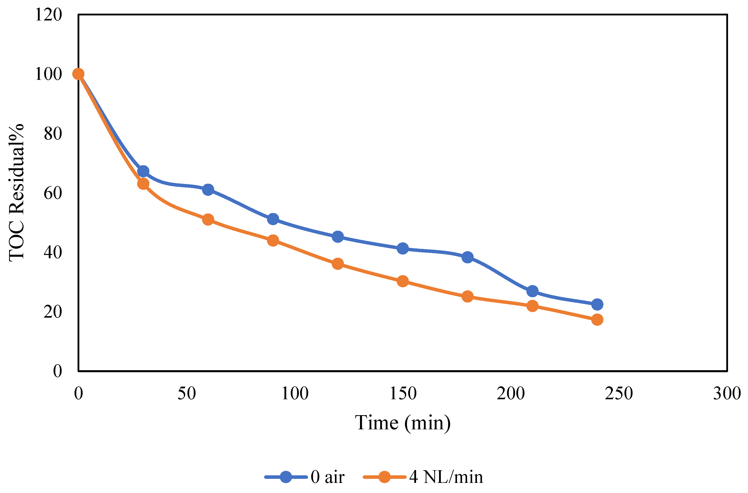
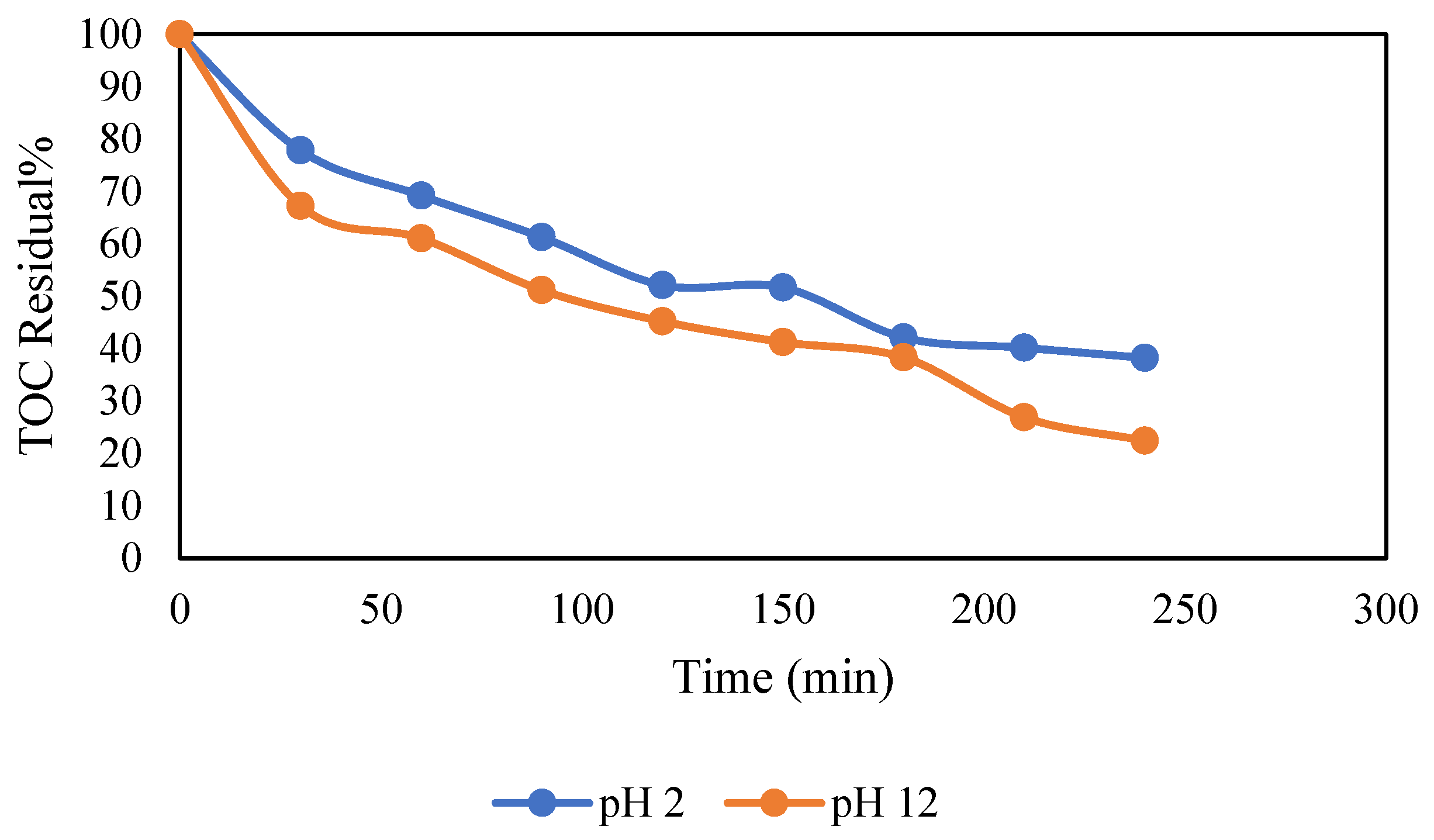
While several studies have investigated wastewater treatment using various electrooxidation methods, research on PW treatment using pilot-scale electrochemical systems with BDD as anode is limited. Therefore, this study focuses on the evaluation of pilot-scale electrochemical treatment system equipped with a BDD for PW treatment. The effects of various factors such as pH, time, current density, and airflow have been evaluated. The findings aim to evaluate the possible applicability and efficacy of BDD in large-scale treatment systems.
2. Materials and Methods
2.1. Reagents
Sodium chloride (NaCl), sodium carbonate (Na2CO3), sodium sulfate (Na2SO4), calcium chloride CaCl2, magnesium chloride MgCl2, Barium chloride BaCl2, strontium Nitrate Sr (NO3)2, and phenol were purchased from Sigma Aldrich (St. Louis, MO, USA) with 99% purity. Sodium dodecyl sulfate SDS (NaC12H25SO4) and phenol (C6H6O) at 99% purity were purchased from Thermo Fisher Scientific (Waltham, MA, USA). Three types of crude oil samples with different densities were obtained from an oil service company in the region.
2.2. Synthesis of Produced Water (PW)
The PW was synthesized according to the protocol proposed by Dardor et al. [
36] with some modifications. A set of successive procedures are used to prepare the synthetic PW. Synthetic brine and phenol are first prepared by dissolving the various salts shown in
Table 1 in one liter of deionized water. After that, 1000 mL of this brine is transferred to a 2 L beaker, and 150 mg of sodium dodecyl sulfate (SDS) is added to a 730 mg mixture of the 3 types of crude oil as shown in
Table 2 to obtain a 5:1 oil–surfactant weight ratio. The solution was agitated for 30 min. at 1000 rpm. Then, the solution was sonicated for an additional 30 min to stabilize the emulsion. The mixture is then transferred to a separatory funnel and allowed to settle for 4 h to enable the separation of any free oil layer. Subsequently, the aqueous layer is transferred to a glass bottle, and the volume is adjusted to 2.5 L, preparing it for treatment in the pilot electrochemical treatment system.
2.3. Electrochemical Treatment Pilot System
This study utilized a laboratory-scale pilot electrochemical treatment system (ETS) for the treatment of PW, designed and assembled by the Center for Research and Technology—Hellas (CERTH); the ETS features an Electro MP Cell from ElectroCell Co. Tarm, Denmark, a modular plate-and-frame electrochemical cell configurable in divided or undivided cell mode. The cathode comprises a carbon-PTFE GDE, and the anode is a BDD electrode, both with an effective area of 0.01 m
2. A constant current power supply from Delta Electronika (SM 3300-series, Zierikzee, The Netherlands) with a maximum current of 22 A and a voltage of 70 V facilitated the tests. Operating parameters like conductivity, pH, temperature, pressure, and oxidation–reduction potential (ORP) were monitored using sensors at the ETS unit’s input and output. A Supervisory Control and Data Acquisition (SCADA) system governed the pilot plant via a PLC unit, incorporating a Human–Machine Interface (HMI) touch screen and various expansion electronic components. The ETS pilot plant schematic diagram (
Figure 1) is composed of an electrochemical cell (plate-and-frame), a compressed air system, a DC power source, a horizontal multistage pump, an inlet tank, and various sensors measuring operational variables. The air valve from the lab air pipeline fed air to the cathode (GDE), while a regulated air system with valves, a flow meter, a relief valve, and a pressure gauge maintain pressure and airflow. To circulate the produced water (2.5 L volume) to the cell, an inverter-controlled horizontal multistage pump with a maximum flow rate of 2 m
3/h at a head of 50 m was employed, with the liquid flow rate monitored by a float-type flow meter.
2.4. Experimental Procedure
The system was flushed with water prior to initiating the treatment of PW in the pilot ETS. Following that, the system was entirely emptied in order to put the PW sample. This step was repeated after each experiment to ensure the consistency of the results. To ensure homogenization, the feed solution was recirculated within the cell at a flow rate of 0.2 m3/h. After the pH and conductivity measurements in the cell’s inlet and outflow became steady (time zero of the experiment), the power supply was turned on (with the predetermined current levels), and the experiment began. After each experiment, the physicochemical properties (pH, conductivity, and TOC) of all the samples collected at different times (0, 30, 60, 90, 120, 150, 180, 210, and 240 min) were recorded. To determine the TOC in the liquid samples, initially, 5 mL of the sample was transferred into a 40 mL vial, and the volume was adjusted to 40 mL to achieve an 8× dilution. After thoroughly mixing the contents to ensure homogeneity, the sample was injected into the TOC analyzer. The following factors were adjusted in each batch experiment: current density (A/cm2), pH, wastewater sample circulation rate (m3/h), and airflow rate (NL/min), with the goal of identifying the best operational conditions.
2.5. Response Surface Method RSM
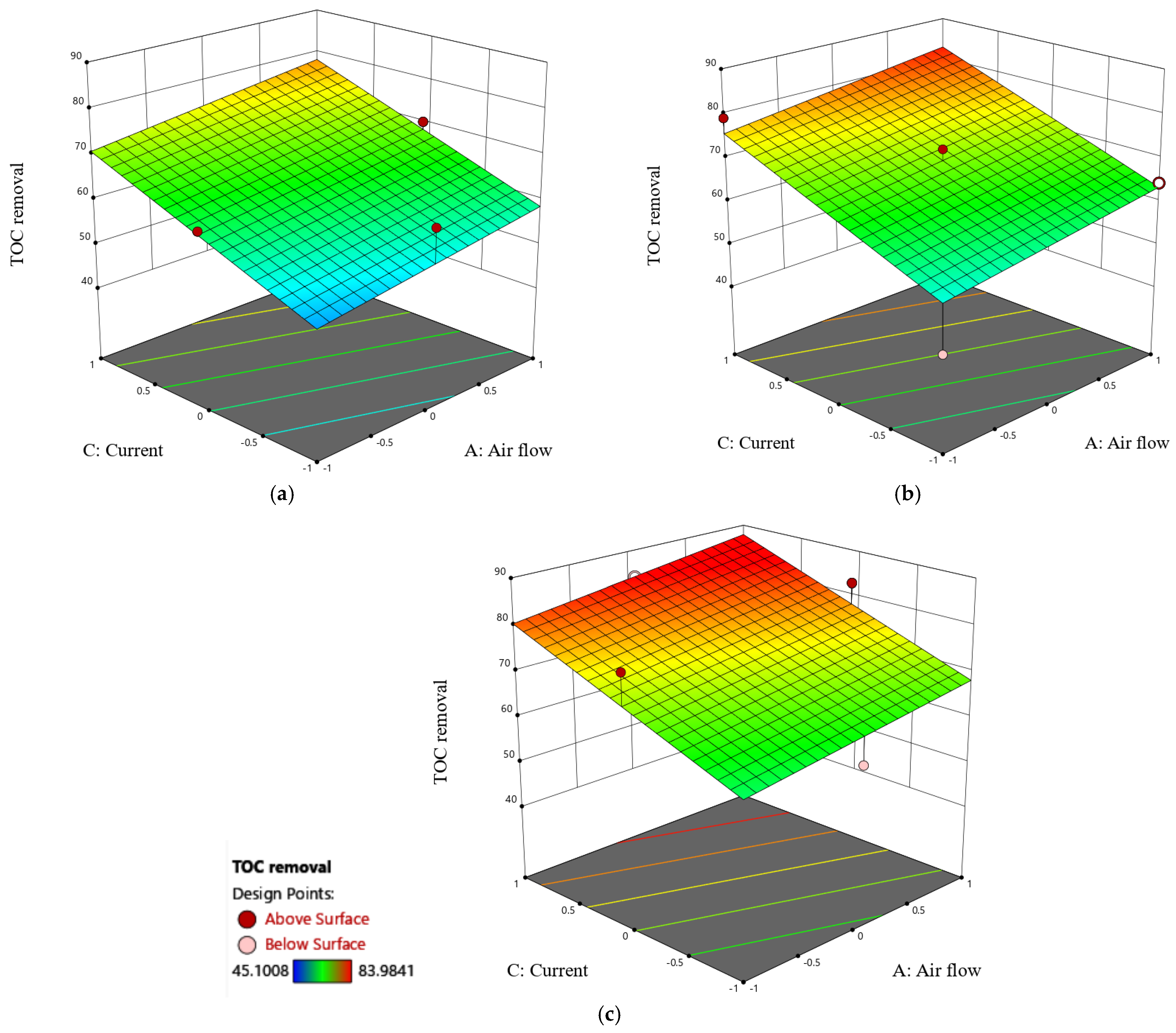
The RSM was used to explore the impacts of various operating parameters on TOC removal rate and energy consumption EC in order to find the best operating conditions. RSM, a statistical method based on a multivariate nonlinear model, is an excellent experimental design method that can reduce the number of experiments while developing a mathematical model that is best suited for the experimental data and optimizes the experimental conditions. In this study, the RSM Box–Benkhen Design (BBD) was applied to optimize the electrochemical process of PW. The three operating parameters: current density (C), airflow (A), and initial pH (B) were selected as independent variables, and their impacts on the TOC removal rate were studied. These parameters were adjusted at the beginning of each run. The experimental design was developed using the Design Expert software (version 12), consisting of 13 experiments each conducted once.
Table 3 depicts the investigated factors and their corresponding levels, which were chosen to cover a wide range of values for each variable.
2.6. Analytical Methods
Analytical methods were employed to assess various parameters in the study. The TOC removal rate served as a key indicator for the degree of treatment in the PW. The TOC was measured using an Analytik Jena multi N/C 3100 TOC analyzer (Analytik Jena AG, Jena, Germany) equipped with an auto-sampler. The conductivity and pH of the produced water were evaluated using a PCD 650 conductivity meter (Eutech Instruments, Singapore). In addition, the MANTECH PC-BOD Multi-parameter analyzer (MANTECH Inc., Guelph, ON, Canada) was used to measure other parameters such as alkalinity, turbidity, and conductivity, ensuring a thorough examination of the water characteristics. The anion and cation concentrations were determined using a dual-column Metrohm 850 Professional IC (Metrohm AG, Herisau, Switzerland). UV-Vis Spectrometer (Analytik Jena SPECORD-50, Analytik Jena AG, Jena, Germany) was used to measure the absorbance of PW at a wavelength of 254 nm.
The removal efficiency of ETS for PW was calculated using Equation (1).
where
Co and
Ct are the initial and concentration at time
t of
TOC, respectively. The average current efficiency (%
CE) for each treated solution at a particular time (
t) was computed using Equation (2) [
37], where
Co and
Ct are the initial and concentration at time
t of
TOC (gL
−1),
F is the Faraday constant 96,487 mol
−1,
I is the current in Amps,
V is the volume of solution (L), and
t is the reaction time.
The energy consumption per unit of
TOC mass at a particular time was calculated using Equation (3) [
38], where
E cell is the supply voltage (
V),
t is electrolysis time (h), Δ
TOC is the change in
TOC concentration (mgL
−1),
V is the volume (L), and
I is the current (A).


