
Enhanced Electrochemical Performance of Dual-Ion Batteries with T-Nb2O5/Nitrogen-Doped Three-Dimensional Porous Carbon Composites

Abstract

1. Introduction
2. Results and Discussion
2.1. Synthesis and Characterization of Materials
2.2. Battery Dynamics Analysis
3. Materials and Methods
4. Conclusions
Supplementary Materials
Author Contributions
Funding
Institutional Review Board Statement
Informed Consent Statement
Data Availability Statement
Acknowledgments
Conflicts of Interest
References
- Semeraro, C.; Olabi, A.G.; Aljaghoub, H.; Alami, A.H.; Al Radi, M.; Dassisti, M.; Abdelkareem, M.A. Digital twin application in energy storage: Trends and challenges. J. Energy Storage 2023, 58, 106347. [Google Scholar] [CrossRef]
- Silva, L.F.O.; Santosh, M.; Schindler, M.; Gasparotto, J.; Dotto, G.L.; Oliveira, M.L.S.; Hochella, M.F., Jr. Nanoparticles in fossil and mineral fuel sectors and their impact on environment and human health: A review and perspective. Gondwana Res. 2021, 92, 184–201. [Google Scholar] [CrossRef]
- Hassan, Q.; Algburi, S.; Sameen, A.Z.; Salman, H.M.; Jaszczur, M. A review of hybrid renewable energy systems: Solar and wind-powered solutions: Challenges, opportunities, and policy implications. Results Eng. 2023, 20, 101621. [Google Scholar] [CrossRef]
- Feng, X.; Guo, Z.; Luo, G.; Wu, C.; Qin, W. Structure-modulation of flower-like VS2 via ammonium ion intercalation for high performance potassium-ion batteries. Vacuum 2024, 227, 113393. [Google Scholar] [CrossRef]
- Subramanyan, K.; Divya, M.L.; Aravindan, V. Dual-carbon Na-ion capacitors: Progress and future prospects. J. Mater. Chem. A 2021, 9, 9431–9450. [Google Scholar] [CrossRef]
- Zhang, L.; Wang, H.; Zhang, X.; Tang, Y. A Review of Emerging Dual-Ion Batteries: Fundamentals and Recent Advances. Adv. Funct. Mater. 2021, 31, 2010958. [Google Scholar] [CrossRef]
- Deng, X.; Li, L.; Zhang, G.; Zhao, X.; Hao, J.; Han, C.; Li, B. Anode chemistry in calcium ion batteries: A review. Energy Storage Mater. 2022, 53, 467–481. [Google Scholar] [CrossRef]
- Rajagopalan, R.; Tang, Y.; Ji, X.; Jia, C.; Wang, H. Advancements and Challenges in Potassium Ion Batteries: A Comprehensive Review. Adv. Funct. Mater. 2020, 30, 1909486. [Google Scholar] [CrossRef]
- Das, A.; Balakrishnan, N.T.M.; Sreeram, P.; Fatima, M.J.J.; Joyner, J.D.; Thakur, V.K.; Pullanchiyodan, A.; Ahn, J.-H.; Raghavan, P. Prospects for magnesium ion batteries: A compreshensive materials review. Coord. Chem. Rev. 2024, 502, 215593. [Google Scholar] [CrossRef]
- Tay, I.R.; Xue, J.; Lee, W.S.V. Methods for Characterizing Intercalation in Aqueous Zinc Ion Battery Cathodes: A Review. Adv. Sci. 2023, 10, 2303211. [Google Scholar] [CrossRef] [PubMed]
- Placke, T.; Fromm, O.; Lux, S.F.; Bieker, P.; Rothermel, S.; Meyer, H.-W.; Passerini, S.; Winter, M. Reversible Intercalation of Bis(trifluoromethanesulfonyl)imide Anions from an Ionic Liquid Electrolyte into Graphite for High Performance Dual-Ion Cells. J. Electrochem. Soc. 2012, 159, A1755. [Google Scholar] [CrossRef]
- Zhang, F.; Ji, B.; Tong, X.; Sheng, M.; Zhang, X.; Lee, C.-S.; Tang, Y. A Dual-Ion Battery Constructed with Aluminum Foil Anode and Mesocarbon Microbead Cathode via an Alloying/Intercalation Process in an Ionic Liquid Electrolyte. Adv. Mater. Interfaces 2016, 3, 1600605. [Google Scholar] [CrossRef]
- Li, N.; Xin, Y.; Chen, H.; Jiao, S.; Jiang, H.; Song, W.-L.; Fang, D. Thickness evolution of graphite-based cathodes in the dual ion batteries via in operando optical observation. J. Energy Chem. 2019, 29, 122–128. [Google Scholar] [CrossRef]
- Placke, T.; Schmuelling, G.; Kloepsch, R.; Meister, P.; Fromm, O.; Hilbig, P.; Meyer, H.-W.; Winter, M. In situ X-ray Diffraction Studies of Cation and Anion Intercalation into Graphitic Carbons for Electrochemical Energy Storage Applications. Z. Anorg. Allg. Chem. 2014, 640, 1996–2006. [Google Scholar] [CrossRef]
- Hao, J.; Li, X.; Song, X.; Guo, Z. Recent progress and perspectives on dual-ion batteries. EnergyChem 2019, 1, 100004. [Google Scholar] [CrossRef]
- Wang, M.; Tang, Y. A Review on the Features and Progress of Dual-Ion Batteries. Adv. Energy Mater. 2018, 8, 1703320. [Google Scholar] [CrossRef]
- Zhao, Z.; Alshareef, H.N. Sustainable Dual-Ion Batteries beyond Li. Adv. Mater. 2024, 36, 2309223. [Google Scholar] [CrossRef] [PubMed]
- Rodríguez-Pérez, I.A.; Ji, X. Anion Hosting Cathodes in Dual-Ion Batteries. ACS Energy Lett. 2017, 2, 1762–1770. [Google Scholar] [CrossRef]
- Wang, G.; Yu, M.; Feng, X. Carbon materials for ion-intercalation involved rechargeable battery technologies. Chem. Soc. Rev. 2021, 50, 2388–2443. [Google Scholar] [CrossRef]
- Zhao, W.; Zhao, C.; Wu, H.; Li, L.; Zhang, C. Progress, challenge and perspective of graphite-based anode materials for lithium batteries: A review. J. Energy Storage 2024, 81, 110409. [Google Scholar] [CrossRef]
- Lu, J.; Chen, Z.; Pan, F.; Cui, Y.; Amine, K. High-Performance Anode Materials for Rechargeable Lithium-Ion Batteries. Electrochem. Energy Rev. 2018, 1, 35–53. [Google Scholar] [CrossRef]
- Majid, A.; Fatima, S.A.; Ud-Din Khan, S.; Almutairi, Z.A. Assessment of 2H–SiC based intercalation compound for use as anode in lithium ion batteries. Ceram. Int. 2020, 46, 5297–5305. [Google Scholar] [CrossRef]
- Yang, C.; Xie, H.; Ping, W.; Fu, K.; Liu, B.; Rao, J.; Dai, J.; Wang, C.; Pastel, G.; Hu, L. An Electron/Ion Dual-Conductive Alloy Framework for High-Rate and High-Capacity Solid-State Lithium-Metal Batteries. Adv. Mater. 2019, 31, 1804815. [Google Scholar] [CrossRef] [PubMed]
- Song, K.; Liu, C.; Mi, L.; Chou, S.; Chen, W.; Shen, C. Recent Progress on the Alloy-Based Anode for Sodium-Ion Batteries and Potassium-Ion Batteries. Small 2021, 17, 1903194. [Google Scholar] [CrossRef]
- Fan, S.; Liu, H.; Bi, S.; Gao, C.; Meng, X.; Wang, Y. Insight on the conversion reaction mechanism of NiCo2S4@CNTs as anode materials for lithium ion batteries and sodium ion batteries. Electrochim. Acta 2021, 388, 138618. [Google Scholar] [CrossRef]
- Hao, S.-M.; Qu, J.; Chang, W.; Zhang, Y.-J.; Tang, Y.; Yu, Z.-Z. A High-Performance Dual-Ion Battery Enabled by Conversion-Type Manganese Silicate Anodes with Enhanced Ion Accessibility. ChemElectroChem 2019, 6, 1040–1046. [Google Scholar] [CrossRef]
- Liang, Y.; Luo, C.; Wang, F.; Hou, S.; Liou, S.-C.; Qing, T.; Li, Q.; Zheng, J.; Cui, C.; Wang, C. An Organic Anode for High Temperature Potassium-Ion Batteries. Adv. Energy Mater. 2019, 9, 1802986. [Google Scholar] [CrossRef]
- Zhou, R.; Hou, Z.; Fan, K.; Wun, C.K.; Liu, Q.; Benedict Lo, T.W.; Huang, H.; Zhang, B. An advanced organic cathode for non-aqueous and aqueous calcium-based dual ion batteries. J. Power Sources 2023, 569, 232995. [Google Scholar] [CrossRef]
- Liu, J.-H.; Wang, P.; Gao, Z.; Li, X.; Cui, W.; Li, R.; Ramakrishna, S.; Zhang, J.; Long, Y.-Z. Review on electrospinning anode and separators for lithium ion batteries. Renew. Sustain. Energy Rev. 2024, 189, 113939. [Google Scholar] [CrossRef]
- Tang, B.; Wei, Y.; Jia, R.; Zhang, F.; Tang, Y. Rational Design of High-Loading Electrodes with Superior Performances Toward Practical Application for Energy Storage Devices. Small 2024, 20, 2308126. [Google Scholar] [CrossRef] [PubMed]
- Chen, C.; Yao, W.; Tang, Y. Emerging Solutions to Enable the Efficient Use of Sodium Metal Anodes: Progress and Perspectives. Adv. Funct. Mater. 2024, 34, 2310833. [Google Scholar] [CrossRef]
- Chen, C.; Lee, C.-S.; Tang, Y. Fundamental Understanding and Optimization Strategies for Dual-Ion Batteries: A Review. Nano-Micro Lett. 2023, 15, 121. [Google Scholar] [CrossRef]
- Wu, H.; Luo, S.; Wang, H.; Li, L.; Fang, Y.; Zhang, F.; Gao, X.; Zhang, Z.; Yuan, W. A Review of Anode Materials for Dual-Ion Batteries. Nano-Micro Lett. 2024, 16, 252. [Google Scholar] [CrossRef] [PubMed]
- Wang, R.; Wang, L.; Liu, R.; Li, X.; Wu, Y.; Ran, F. “Fast-Charging” Anode Materials for Lithium-Ion Batteries from Perspective of Ion Diffusion in Crystal Structure. ACS Nano 2024, 18, 2611–2648. [Google Scholar] [CrossRef] [PubMed]
- Liu, W.; Liu, P.; Mitlin, D. Review of Emerging Concepts in SEI Analysis and Artificial SEI Membranes for Lithium, Sodium, and Potassium Metal Battery Anodes. Adv. Energy Mater. 2020, 10, 2002297. [Google Scholar] [CrossRef]
- Chen, Y.; Pu, Z.; Liu, Y.; Shen, Y.; Liu, S.; Liu, D.; Li, Y. Enhancing the low-temperature performance in lithium ion batteries of Nb2O5 by combination of W doping and MXene addition. J. Power Sources 2021, 515, 230601. [Google Scholar] [CrossRef]
- Chen, G.; Chen, J.; Zhao, S.; He, G.; Miller, T.S. Pseudohexagonal Nb2O5 Anodes for Fast-Charging Potassium-Ion Batteries. ACS Appl. Mater. Interfaces 2023, 15, 16664–16672. [Google Scholar] [CrossRef]
- Ji, Q.; Chen, W.; Chen, X.; Wang, X.; Dong, Q.; Yin, S.; Shen, Y.; Müller-Buschbaum, P.; Cheng, Y.-J.; Xia, Y. Synergistic Effect of Dual Phases to Improve Lithium Storage Properties of Nb2O5. ACS Appl. Mater. Interfaces 2024, 16, 7232–7242. [Google Scholar] [CrossRef] [PubMed]
- Cheong, J.Y.; Kim, C.; Jung, J.-W.; Yoon, K.R.; Cho, S.-H.; Youn, D.-Y.; Jang, H.-Y.; Kim, I.-D. Formation of a Surficial Bifunctional Nanolayer on Nb2O5 for Ultrastable Electrodes for Lithium-Ion Battery. Small 2017, 13, 1603610. [Google Scholar] [CrossRef] [PubMed]
- So, S.; Ahn, Y.N.; Ko, J.; Kim, I.T.; Hur, J. Uniform and oriented zinc deposition induced by artificial Nb2O5 Layer for highly reversible Zn anode in aqueous zinc ion batteries. Energy Storage Mater. 2022, 52, 40–51. [Google Scholar] [CrossRef]
- Das, P.; Ibrahim, S.; Chakraborty, K.; Ghosh, S.; Pal, T. Stepwise reduction of graphene oxide and studies on defect-controlled physical properties. Sci. Rep. 2024, 14, 294. [Google Scholar] [CrossRef] [PubMed]
- Li, Y.; Song, Z.; Sun, T.; Shen, Y.; Lv, X.; Xu, D.; Wang, H.-G. Well-dispersed Sb2O3 nanoparticles encapsulated in multi-channel-carbon nanofibers as high-performance anode materials for Li/dual-ion batteries. Int. J. Hydrogen Energy 2021, 46, 26308–26317. [Google Scholar] [CrossRef]
- Sui, L.; Shi, X.; Deng, T.; Yang, H.; Liu, H.; Chen, H.; Zhang, W.; Zheng, W. Integrated Co3O4/carbon fiber paper for high-performance anode of dual-ion battery. J. Energy Chem. 2019, 37, 7–12. [Google Scholar] [CrossRef]
- Zheng, C.; Wu, J.; Li, Y.; Liu, X.; Zeng, L.; Wei, M. High-Performance Lithium-Ion-Based Dual-Ion Batteries Enabled by Few-Layer MoSe2/Nitrogen-Doped Carbon. ACS Sustain. Chem. Eng. 2020, 8, 5514–5523. [Google Scholar] [CrossRef]
- Liu, X.; Liu, Y.; Yan, X.; Lan, J.-L.; Yu, Y.; Yang, X. Ultrafine MoO3 nanoparticles embedded in porous carbon nanofibers as anodes for high-performance lithium-ion batteries. Mater. Chem. Front. 2019, 3, 120–126. [Google Scholar] [CrossRef]
- Anjali, A.; Jayan, P.; Akshay, M.; Lee, Y.-S.; Aravindan, V. SnO2 as an alloy anode for Li-based dual-ion battery with enhanced performance. Next Mater. 2024, 2, 100117. [Google Scholar] [CrossRef]
- Zhang, F.; Wu, M.; Wang, X.; Xiang, Q.; Wu, Y.; Ding, J.; Sun, Y. Reversible multi-electron redox chemistry of organic salt as anode for high-performance Li-ion/dual-ion batteries. Chem. Eng. J. 2023, 457, 141335. [Google Scholar] [CrossRef]


| Samples | SBET (m2/g) | Vt (cm3/g) | Dmeso (nm) |
|---|---|---|---|
| RMF | 1008.6 | 4.51 | 15.13 |
| T-Nb2O5/RMF | 1568.5 | 2.79 | 7.56 |
| T-Nb2O5/GO | 263.9 | 0.61 | 4.11 |
| T-Nb2O5/CNTs | 135.3 | 0.40 | 3.78 |
| Electrolyte | Specific Capacity | Reference |
|---|---|---|
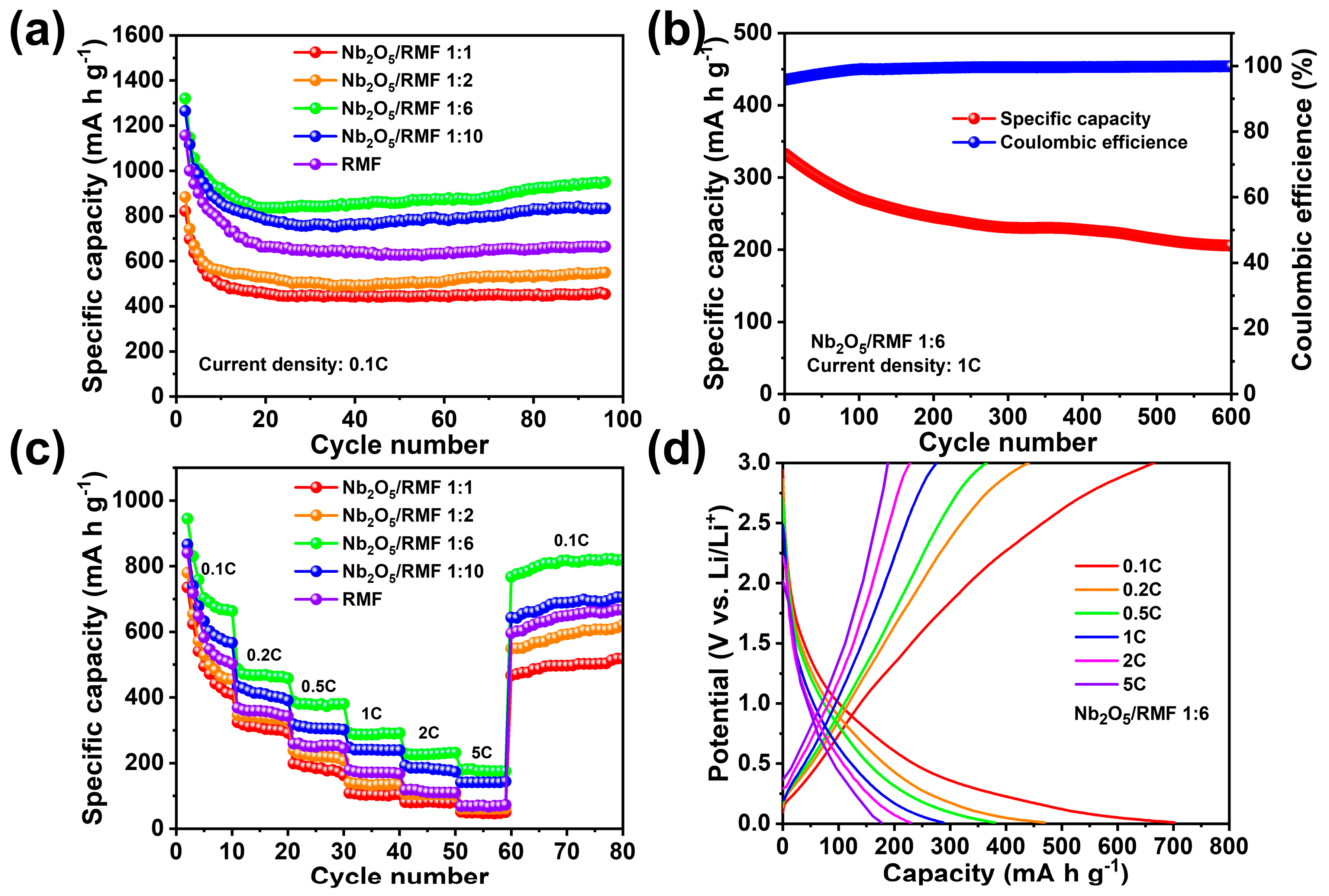
| T-Nb2O5/RMF | 945 mA h g−1 after 100 cycles at 100 mA g−1 | This work |
| Co3O4/carbon fiber paper (CFP) | 488 mA h g−1 after 40 cycles at 200 mA g−1 | [43] |
| MoSe2/nitrogen-doped carbon (NC) | 759 mA h g−1 after 100 cycles at 100 mA g−1 | [44] |
| MoO2/carbon matrix | 734 mA h g−1 after 350 cycles at 50 mA g−1 | [45] |
| SnO2 | 613 mA h g−1 after 60 cycles at 60 mA g−1 | [46] |
| Li6C12O12 | 730 mA h g−1 after 100 cycles at 210 mA g−1 | [47] |
| Sb2O3@MCNF | 626.9 mA h g−1 after 80 cycles at 100 mA g−1 | [42] |
Disclaimer/Publisher’s Note: The statements, opinions and data contained in all publications are solely those of the individual author(s) and contributor(s) and not of MDPI and/or the editor(s). MDPI and/or the editor(s) disclaim responsibility for any injury to people or property resulting from any ideas, methods, instructions or products referred to in the content. |
© 2025 by the authors. Licensee MDPI, Basel, Switzerland. This article is an open access article distributed under the terms and conditions of the Creative Commons Attribution (CC BY) license (https://creativecommons.org/licenses/by/4.0/).
Share and Cite
Qi, C.; Ying, D.; Ma, C.; Qiao, W.; Wang, J.; Ling, L. Enhanced Electrochemical Performance of Dual-Ion Batteries with T-Nb2O5/Nitrogen-Doped Three-Dimensional Porous Carbon Composites. Molecules 2025, 30, 227. https://doi.org/10.3390/molecules30020227
Qi C, Ying D, Ma C, Qiao W, Wang J, Ling L. Enhanced Electrochemical Performance of Dual-Ion Batteries with T-Nb2O5/Nitrogen-Doped Three-Dimensional Porous Carbon Composites. Molecules. 2025; 30(2):227. https://doi.org/10.3390/molecules30020227
Chicago/Turabian StyleQi, Chen, Duo Ying, Cheng Ma, Wenming Qiao, Jitong Wang, and Licheng Ling. 2025. "Enhanced Electrochemical Performance of Dual-Ion Batteries with T-Nb2O5/Nitrogen-Doped Three-Dimensional Porous Carbon Composites" Molecules 30, no. 2: 227. https://doi.org/10.3390/molecules30020227
APA StyleQi, C., Ying, D., Ma, C., Qiao, W., Wang, J., & Ling, L. (2025). Enhanced Electrochemical Performance of Dual-Ion Batteries with T-Nb2O5/Nitrogen-Doped Three-Dimensional Porous Carbon Composites. Molecules, 30(2), 227. https://doi.org/10.3390/molecules30020227