Article

Boosting Photoelectrochemical Water Splitting via InPOx-Coated TiO2 Nanowire Photoanodes

1
Department of Chemical Engineering & Biotechnology, National Taipei University of Technology, Taipei City 10608, Taiwan
2
Department of Opto-Electronic Engineering, National Dong Hwa University, No. 1, Sec. 2, Da Hsueh Road, Shoufeng, Hualien 97401, Taiwan
*
Author to whom correspondence should be addressed.
Molecules 2025, 30(17), 3482; https://doi.org/10.3390/molecules30173482 (registering DOI)
Submission received: 21 July 2025 / Revised: 21 August 2025 / Accepted: 23 August 2025 / Published: 25 August 2025
(This article belongs to the Special Issue Photochemistry in Asia)

Abstract

A hierarchical photoanode composed of amorphous indium phosphate (InPOx)-coated titanium dioxide nanowires (TiO2 NWs) was successfully fabricated via a hydrothermal method followed by dip-coating and thermal phosphidation. Structural characterization revealed the formation of a uniform InPOx shell on the surface of vertically aligned TiO2 NWs, without altering their 1D morphology. X-ray photoelectron spectroscopy confirmed the incorporation of phosphate species and the presence of oxygen vacancies, which contribute to enhanced interfacial charge dynamics. Photoelectrochemical (PEC) measurements demonstrated that the InPOx/TiO2 NWs significantly improved photocurrent density, with the 0.1 M InCl3-derived sample achieving 0.36 mA·cm−2 at 1.0 V—an enhancement of approximately 928% over pristine TiO2. This enhancement is attributed to improved charge separation and injection efficiency (91%), as well as reduced interfacial resistance verified by electrochemical impedance spectroscopy. Moreover, the Mott–Schottky analysis indicated a four-order increase in carrier density due to the InPOx shell. The modified electrode also exhibited superior stability under continuous illumination for 3 h. These findings highlight the potential of amorphous InPOx as an effective cocatalyst for constructing efficient and durable TiO2-based photoanodes for solar-driven water-splitting applications.

1. Introduction

With the growing global demand for clean energy and sustainable hydrogen production, significant efforts have been devoted to utilizing solar energy for water splitting. However, the intermittent and decentralized nature of solar irradiation poses practical challenges to energy conversion. Among various strategies, photoelectrochemical (PEC) water splitting has emerged as a promising approach for direct solar-to-hydrogen conversion [1]. To date, various n-type semiconductors—such as TiO2, Fe2O3, BiVO4, and ZnO—have been investigated as photoanode materials for PEC water oxidation [2,3,4,5]. TiO2, in particular, has attracted widespread attention due to its chemical stability, abundance, and appropriate band-edge positions. Nevertheless, its wide bandgap (~3.2 eV for anatase), short charge diffusion length, and sluggish surface reaction kinetics significantly limit its PEC efficiency. One viable strategy to overcome these drawbacks is the construction of composite photoelectrodes with optimized compositions and nanostructures. For example, forming semiconductor heterojunctions or decorating the surface with oxygen evolution reaction (OER) cocatalysts can effectively enhance charge separation and lower the reaction barriers [6]. While incorporating narrow-bandgap semiconductors or cocatalysts onto TiO2 surfaces is a common tactic, such modifications may compromise its intrinsic UV light absorption [7,8,9]. Alternatively, coupling TiO2 with a wide bandgap cocatalyst offers a promising path to enhance charge separation without sacrificing light harvesting. Recently, Gao et al. reported improved PEC performance by combining In2S3 nanosheets with InPOx overlays. InPOx compounds, such as InPO4, exhibit wide bandgaps (e.g., ~4.5 eV), making them suitable candidates for this approach [10,11]. In this study, we deposited InPOx shells onto TiO2 nanowires via dip-coating followed by thermal phosphidation. Compared to bare TiO2, the resulting InPOx/TiO2 photoanode exhibited a tenfold increase in photocurrent at 1 V vs. Ag/AgCl in 0.5 M Na2SO4, indicating substantially improved PEC performance. This work not only advances the design of efficient photoelectrodes through band structure modulation but also opens new avenues for 3D hierarchical nanomaterials in solar energy and electronic applications.

2. Results and Discussion

2.1. Structure and Composition Characterization

The morphological evolution of the InPOx/TiO2 nanowires (NWs) was investigated using scanning electron microscopy (SEM). As shown in Figure 1a, the pristine TiO2 NWs synthesized via the hydrothermal method exhibit a dense, wire-like structure that uniformly covers a large area of the Ti foil substrate. The NWs have diameters ranging from 20 to 150 nm and lengths extending to several tens of micrometers. Figure 1b–d present the surface morphologies of the TiO2 NWs after deposition of the InPOx layer using InCl3 solutions with concentrations of 0.05, 0.1, and 0.15 M, respectively. The 1D morphology and density of the NWs remain unchanged across all samples. The mean nanowire diameter increases from 26 nm (pristine) to 33 nm (0.05 M), 42 nm (0.1 M), and 47 nm (0.15 M). However, a noticeable increase in both nanowire diameter and surface roughness is observed, indicating the successful formation of an InPOx shell layer on the TiO2 NWs.
To further confirm the core–shell structure, transmission electron microscopy (TEM) images of the pristine TiO2 NWs and InPOx/TiO2 NWs (prepared with 0.1 M InCl3) are shown in Figure 1e and Figure 1f, respectively. The pristine TiO2 NWs exhibit smooth surfaces, whereas the InPOx/TiO2 NWs display a rougher surface with an additional layer. This overlayer corresponds to an InPOx shell with an estimated thickness of 2–15 nm, validating the successful deposition of the amorphous coating.
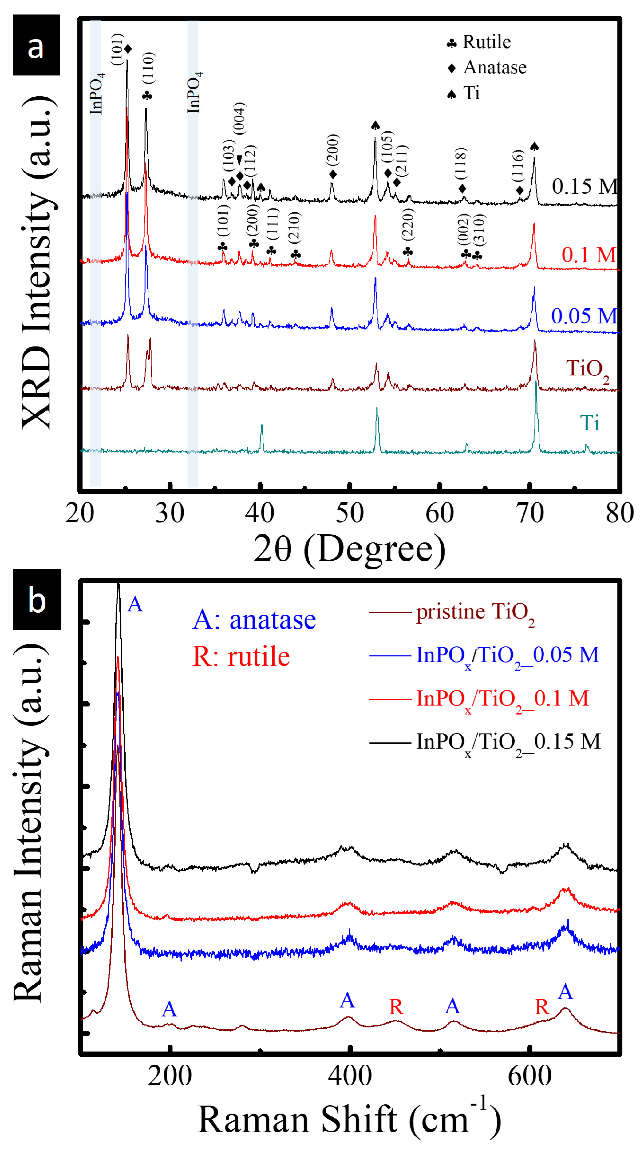
X-ray diffraction (XRD) was employed to investigate the crystallographic structure of the InPOx/TiO2 heterostructure, as shown in Figure 2a. For comparison, XRD patterns of the bare TiO2 NWs and the Ti foil substrate are also included. Both the pristine and InPOx-modified TiO2 NW samples exhibit diffraction peaks that can be indexed to two TiO2 polymorphs. The peaks labeled with diamonds correspond to anatase TiO2 (JCPDS No. 21-1272), including the (101), (004), and (200) reflections. The peaks marked with plum blossom symbols are attributed to the rutile TiO2 phase (JCPDS No. 88-1175), corresponding to the (110), (101), and (002) planes. Lattice parameters of anatase (a = 3.785 Å, c = 9.514 Å) and rutile (a = 4.593 Å, c = 2.958 Å) were extracted. These values are in excellent agreement (within ±0.3%) with the standard phases, confirming phase purity and structural stability during InPOx deposition. The average crystallite sizes of the (101) anatase and (110) rutile reflections are ~22 nm and ~28 nm, respectively. Aside from these, diffraction peaks arising from the underlying Ti substrate (marked with spades) are also observed. Importantly, no additional diffraction peaks corresponding to InPOx phases are detected, suggesting that the InPOx coating is amorphous in nature. To further examine the phase composition, Raman spectroscopy was conducted on the pristine and InPOx-coated TiO2 NWs with varying InCl3 concentrations (0.05, 0.1, and 0.15 M), as shown in Figure 2b. All samples exhibit five characteristic Raman bands of the anatase phase at 145, 198, 395, 515, and 635 cm−1, corresponding to the Eg, Eg, B1g, A1g (or B1g), and Eg vibrational modes, respectively [12]. In addition, three weaker Raman peaks are observed at 230, 450, and 610 cm−1, which can be attributed to the rutile phase, corresponding to a multiphonon process, Eg mode, and A1g mode, respectively. These findings are consistent with the XRD results and confirm the coexistence of anatase and rutile phases in the TiO2 NWs, with the InPOx layer remaining amorphous.
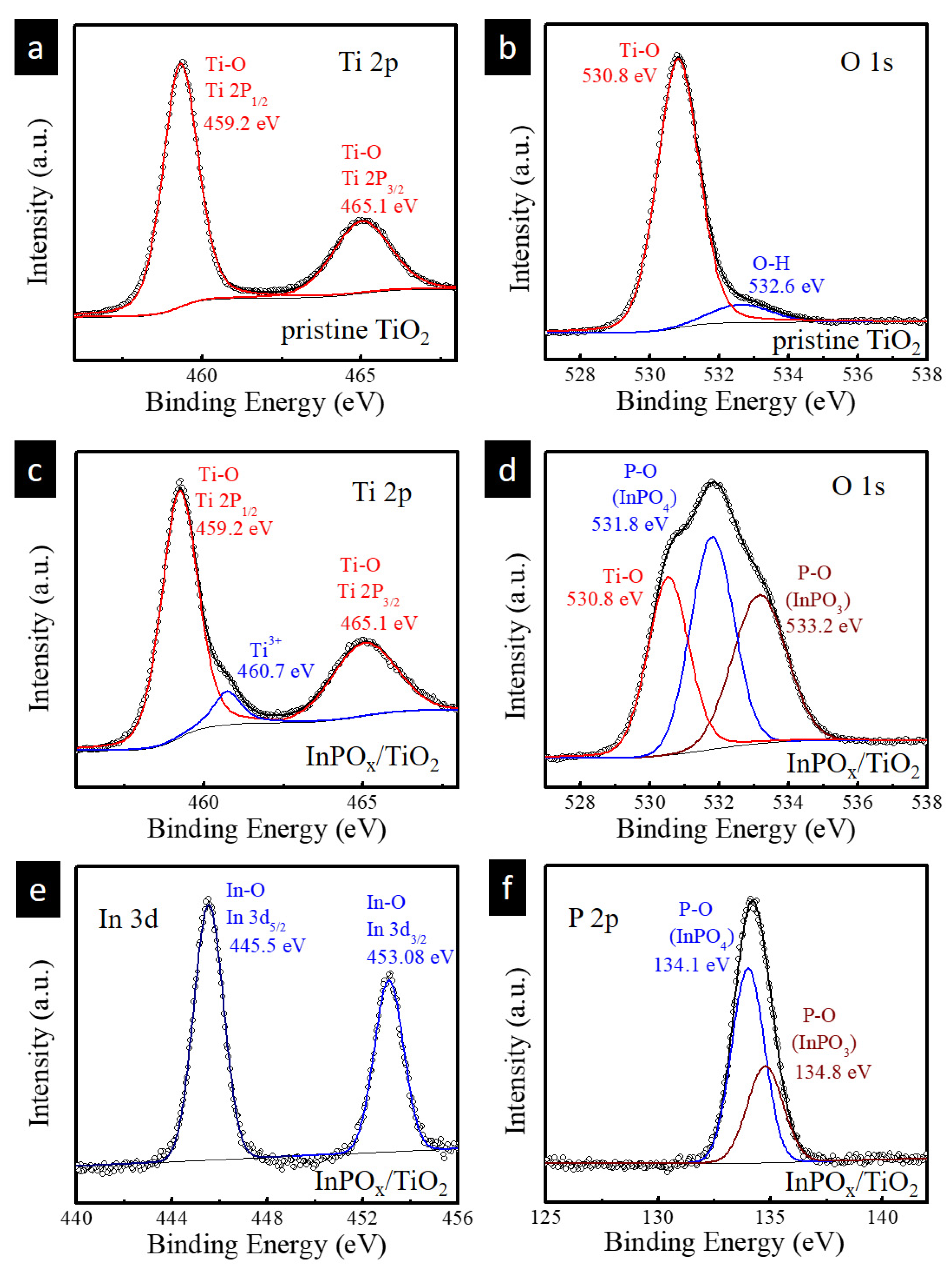
To elucidate the oxidation states of the pristine TiO2 and InPOx/TiO2 NWs (prepared with 0.1 M InCl3), X-ray photoelectron spectroscopy (XPS) analysis was performed. Figure 3a,b show the high-resolution XPS spectra of Ti 2p and O 1s for the pristine TiO2 NWs. Two prominent peaks located at 459.2 eV and 465.1 eV are assigned to Ti 2p3/2 and Ti 2p1/2, respectively. The spin–orbit splitting of approximately 6.0 eV is consistent with the presence of Ti4+, confirming the normal oxidation state of Ti in TiO2, which is in agreement with previously reported data [13]. The O 1s spectrum of the pristine TiO2 NWs can be deconvoluted into two components: a peak at 530.8 eV attributed to the lattice oxygen in Ti–O bonds, and a peak at 532.6 eV corresponding to surface-adsorbed hydroxyl groups (–OH). Upon deposition of the InPOx overlayer, an additional Ti3+ 2p3/2 peak appears at 460.7 eV, suggesting the generation of oxygen vacancies during the thermal phosphidation process [13]. The O 1s spectrum of the InPOx/TiO2 NWs also reveals two additional peaks at 531.8 eV and 533.2 eV, which are ascribed to P–O bonds in InPO4 and InPO3, respectively. These findings support the formation of phosphate-containing species on the TiO2 surface. Furthermore, the high-resolution In 3d XPS spectrum shows two distinct peaks at 445.5 eV and 453.0 eV, corresponding to In 3d5/2 and In 3d3/2 of the InPOx species, respectively. The P 2p spectrum exhibits peaks at 134.1 eV and 134.8 eV, which are consistent with the 2p orbital binding energies of PO33− and PO43− species, respectively [14]. These results collectively confirm the successful formation of an InPOx shell on the surface of the TiO2 NWs through the phosphidation process.
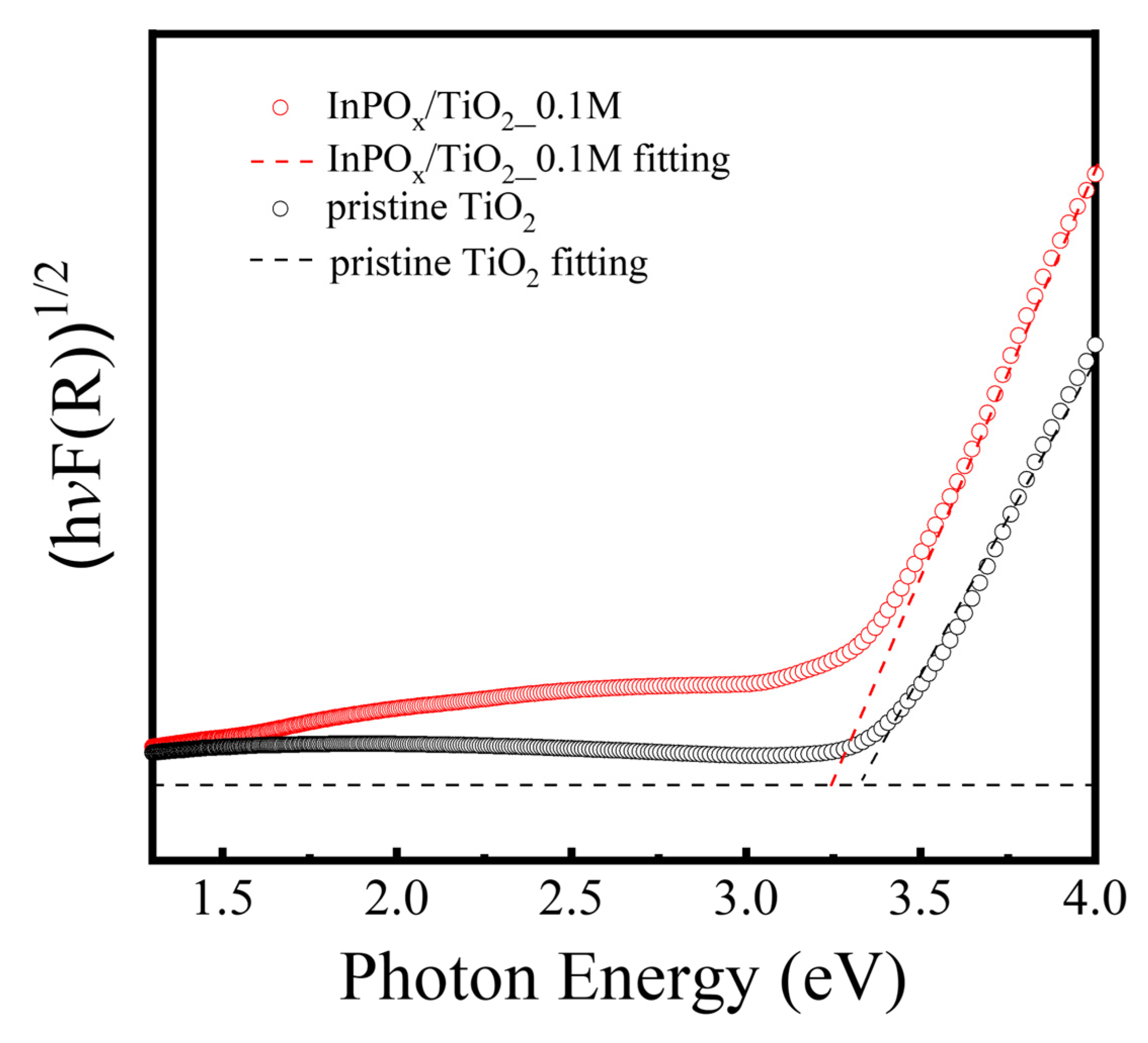
In addition, the optical absorption properties of the pristine TiO2 and InPOx/TiO2 NWs were investigated, as shown in Figure 4. The indirect Tauc plots, derived from (αhv)1/2 versus photon energy (hv), were used to estimate the optical bandgap values of the two samples. Both samples exhibit a bandgap of approximately 3.2 eV, which is consistent with the reported value for anatase TiO2 [15]. Since InPOx is a wide bandgap material, its presence as a surface shell does not significantly affect the light absorption characteristics of the TiO2 NWs. This confirms that the core TiO2 maintains its photoresponsive behavior, while the InPOx layer provides surface modification without impeding optical performance.

2.2. PEC Performance of InPOx/TiO2 NW Photoanode

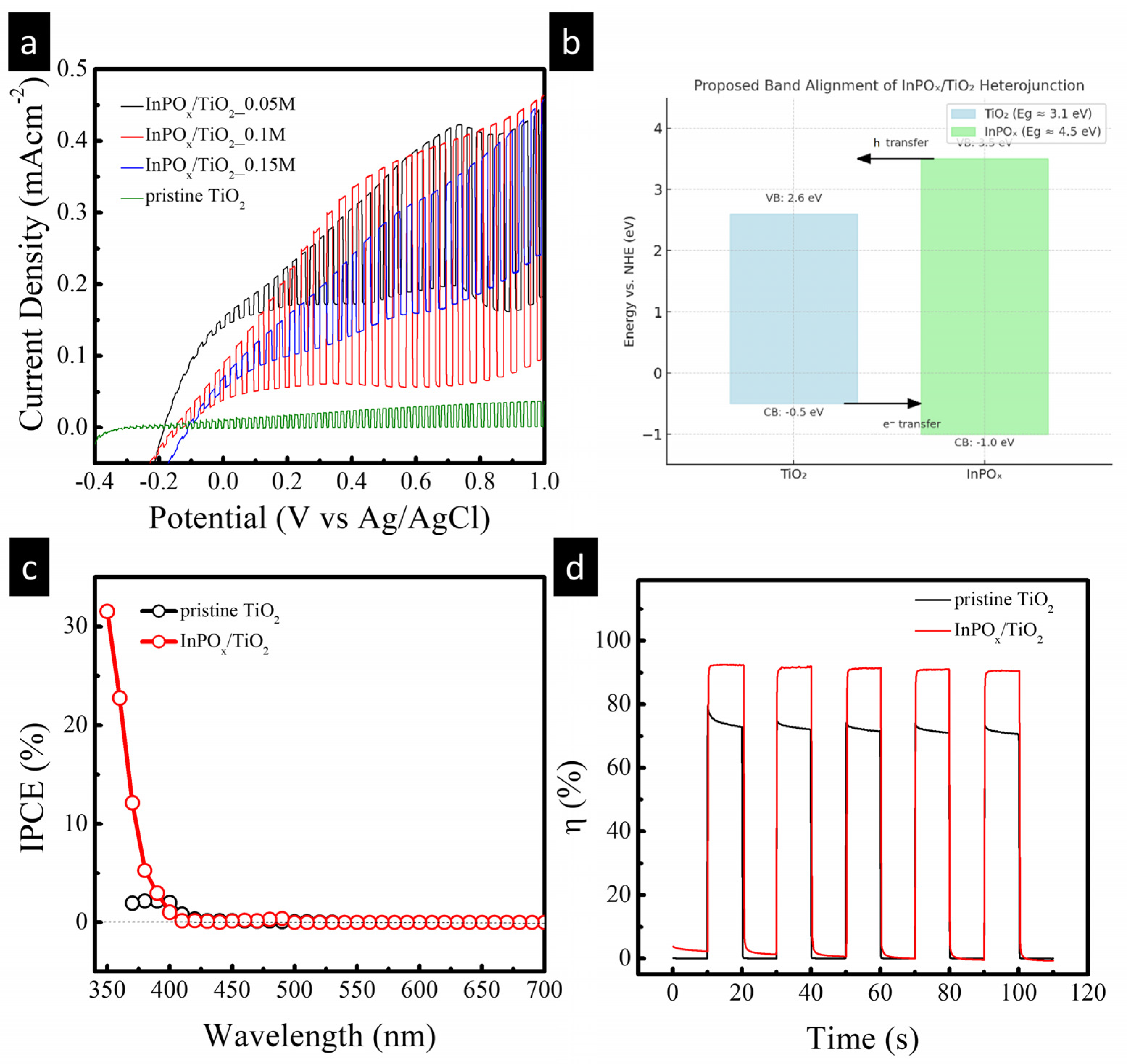
To evaluate the photoelectrochemical (PEC) activity of the InPOx/TiO2 NW electrodes, a standard three-electrode configuration was employed in a 0.5 M Na2SO4 electrolyte. Photocurrent–potential (J–V) curves of pristine TiO2 NWs and InPOx/TiO2 NWs prepared with InCl3 concentrations of 0.05, 0.1, and 0.15 M were measured using linear sweep voltammetry (LSV) under both continuous and chopped illumination, as shown in Figure 5a. The pristine TiO2 NWs displayed a relatively low photocurrent density of approximately 0.035 mA·cm−2 at 0.1 V, which is primarily attributed to inefficient charge separation. Upon deposition of the InPOx layer, all modified samples exhibited a significant enhancement in photocurrent response. This improvement is attributed to the formation of an InPOx/TiO2 heterojunction, which facilitates the separation of photogenerated electron–hole pairs via an internal electric field across the interface. Among the tested samples, the InPOx/TiO2 NWs synthesized with 0.1 M InCl3 showed the highest photocurrent density of 0.36 mA·cm−2 at 1.0 V—nearly an order of magnitude greater than that of the pristine TiO2. This enhancement corresponds to a current gain of approximately 928%, which surpasses the performance of many previously reported TiO2-based heterostructured photoanodes, as summarized in Table 1 [16,17,18,19,20,21]. Based on reported band edge positions of amorphous InPO4 (bandgap ~4.5 eV, CB ≈ −1.0 eV vs. NHE, VB ≈ +3.5 eV) and TiO2 (bandgap ~3.1 eV, CB ≈ −0.5 eV vs. NHE, VB ≈ +2.6 eV), we propose a type-II band alignment at the InPOx/TiO2 interface. In this configuration, photogenerated electrons in the TiO2 conduction band remain available for reduction reactions, while the InPOx layer provides surface states that facilitate hole transfer to the electrolyte and suppress recombination. A schematic band alignment has been added to the revised manuscript (Figure 5b) to illustrate this mechanism and clarify the role of the InPOx shell in enhancing charge separation. The incident photon-to-current conversion efficiency (IPCE) spectra of the pristine TiO2 and InPOx/TiO2 photoanodes are presented in Figure 5c. Measurements were conducted at an applied bias of 0.6 V. Both samples exhibit photocurrent onset at wavelengths around 400 nm, consistent with the bandgap of TiO2 [12]. However, the InPOx-modified sample demonstrates a marked increase in IPCE across the UV region, indicating that the InPOx layer enhances ultraviolet light utilization and thus contributes meaningfully to the overall photocurrent. To further assess the charge injection capability of the InPOx/TiO2 electrode, 0.2 M Na2SO3 was added as a hole scavenger to the 0.5 M Na2SO4 electrolyte. The injection efficiency (η) was calculated using the following relation:
η = j electrolyte/j scavenger
where j electrolyte is the photocurrent density measured in the scavenger-free electrolyte and j scavenger is the photocurrent measured in the presence of the hole scavenger. As shown in Figure 5d, the injection efficiency of the InPOx/TiO2 NWs (0.1 M InCl3) reached approximately 91%, significantly higher than that of pristine TiO2. This enhancement confirms that the amorphous InPOx layer functions as an effective surface cocatalyst, promoting hole transfer to the electrolyte and improving overall charge injection efficiency, consistent with its role discussed in the earlier compositional analysis [22,23].
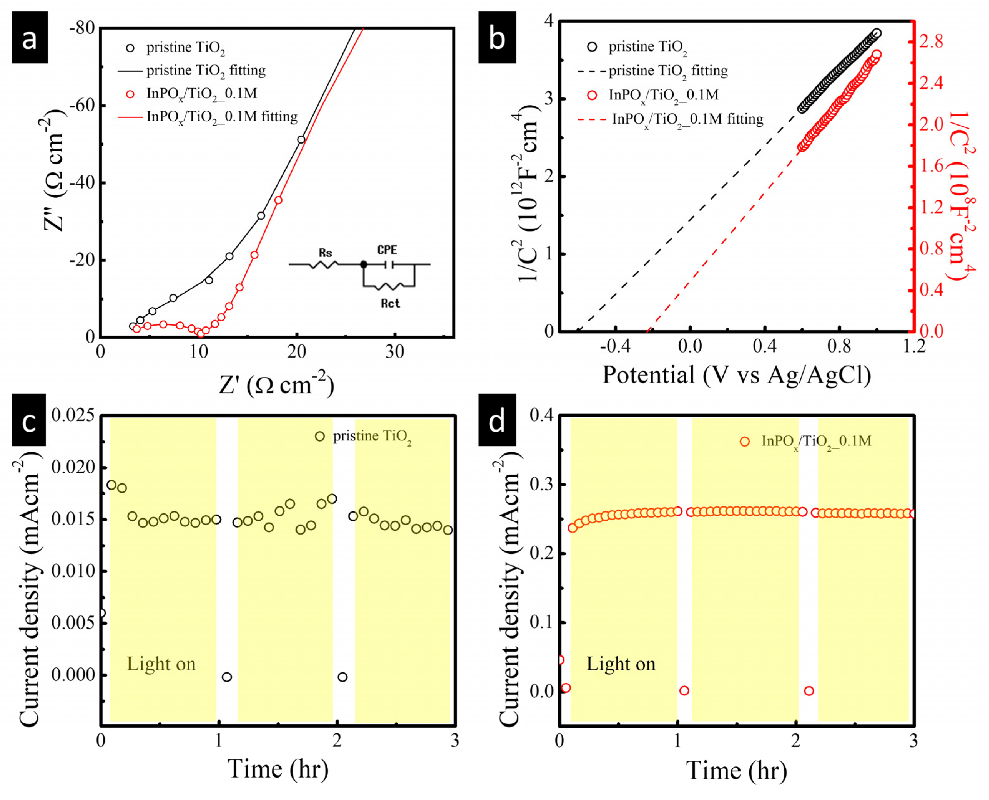
Furthermore, electrochemical impedance spectroscopy (EIS) was performed under light irradiation at an applied potential of 0.6 V to investigate the interfacial charge transfer kinetics. As shown in Figure 6a, the Nyquist plots of the pristine TiO2 and InPOx/TiO2 NW photoelectrodes reveal a significantly smaller semicircular arc for the InPOx-modified sample. This indicates a lower charge transfer resistance and suggests more efficient interfacial charge transfer in the InPOx/TiO2 NWs. These results confirm that the incorporation of the InPOx shell enhances the photoelectrochemical performance by facilitating faster charge transport at the electrode–electrolyte interface. To further understand the electronic properties, Mott–Schottky (M–S) analysis was conducted (Figure 6b). The carrier densities, estimated from the slopes of the M–S plots, were 6.9 × 1017 cm−3 for the pristine TiO2 NWs and 7.5 × 1021 cm−3 for the InPOx/TiO2 NWs. This nearly four-order-of-magnitude increase in carrier density highlights the significant impact of the InPOx overlayer in enhancing charge carrier concentration. Such a substantial enhancement is attributed to the InPOx shell on the TiO2 NW surface, and similar phenomena have also been observed in other InPOx/β-In2S3 heterostructured photoelectrodes [10]. The increased carrier density likely contributes to improved charge separation and transport, both critical factors for PEC performance. Long-term stability tests were also conducted under continuous simulated solar illumination at an applied potential of 0.6 V for 3 h. As shown in Figure 6c, the photocurrent of the pristine TiO2 electrode quickly stabilized after approximately 20 min. By contrast, the InPOx/TiO2 NW photoelectrode maintained a steady photocurrent throughout the entire 3 h period, indicating excellent operational stability. This sustained photocurrent not only confirms the robustness of the InPOx/TiO2 heterostructure under prolonged illumination but also implies that the InPOx shell promotes efficient charge separation at low onset potentials. As a result, the photogenerated electrons more effectively drive the hydrogen evolution reaction, contributing to the enhanced photoresponse observed in the InPOx/TiO2 NW photoanode.

3. Experimental Section

Potassium hydroxide (KOH, 97%), indium trichloride (InCl3, 99%), and sodium hypophosphite (NaH2PO2, 98%) were obtained from Sigma-Aldrich (St. Louis, MO, USA). Ti foil was purchased from Shanghai Sinopharm Chemical Reagent Co., Ltd. (Shanghai, China). Hydrogen chloride (HCl, 30–50%) and sodium sulfate (Na2SO4, 98%) were purchased from Fisher Scientific (Pittsburgh, PA, USA). All chemicals were of analytical grade and used as received without further purification.
The preparation of the InPOx/TiO2 composite began with the growth of a TiO2 nanowire (NW) array on a Ti foil substrate using a hydrothermal method. A piece of Ti foil (0.127 mm thick, 1 cm × 2 cm) was ultrasonically cleaned in deionized water and acetone for 10 min each, then placed at an angle against the wall of a 150 mL Teflon-lined stainless-steel autoclave containing 30 mL of 1 M KOH solution. The autoclave was sealed and maintained at 220 °C in an electric oven for 48 h, resulting in the growth of potassium titanate (K2Ti2O5) NWs on the Ti foil. After cooling to room temperature, the sample was removed and immersed in 100 mL of 0.5 M HCl solution for 2 h to replace K+ ions with H+, thereby converting the potassium titanate NWs into hydrogen titanate (H2Ti2O5) NWs. The foil was then thoroughly rinsed with deionized water. In the next step, the H2Ti2O5 NW-covered Ti foil was annealed at 700 °C for 1 h to convert the NWs into crystalline TiO2 NWs.
The InPOx layer was subsequently deposited on the TiO2 NWs by a dip-coating and thermal annealing process. Specifically, 40 μL of InCl3 solution at varying concentrations (0.05, 0.1, or 0.15 M) was spin-coated onto the TiO2 NWs. After drying, the samples were placed on a preheated hotplate at 100 °C in air for 1 min. This deposition and heating step was defined as one cycle, and ten such cycles were performed. The resulting sample was then placed in the center of a three-zone tube furnace, with 0.1 g of NaH2PO2 added to both ends. After purging the system with N2, the central zone of the furnace was heated to 425 °C and held for 1 h, while both ends were raised to 475 °C. The furnace was then allowed to cool naturally to room temperature, yielding the final InPOx/TiO2 composite.
The morphology of the hierarchical InPOx/TiO2 NW arrays was characterized using scanning electron microscopy (SEM, JEM-4000EX, JEOL, Tokyo, Japan). The chemical states of the constituent elements were analyzed via X-ray photoelectron spectroscopy (XPS, Perkin-Elmer PHI 1600, Shelton, CT, USA). High-resolution scanning transmission electron microscopy (HR-STEM, JEM2010F and JEM2200FS, both operating at 200 kV, JEOL) was employed to investigate the microstructure and chemical composition in detail. Photoelectrochemical (PEC) measurements were conducted in 0.5 M Na2SO4 solution using a potentiostat/galvanostat (CHI 6273D, Shanghai Chenhua Instruments Co., Ltd., Shanghai, China). A conventional three-electrode configuration was used, comprising the InPOx/TiO2 electrode as the working electrode, a square platinum sheet (4 cm2) as the counter electrode, and a Ag/AgCl electrode in 3 M KCl as the reference. All potentials in this study are reported versus the Ag/AgCl reference electrode. A 150 W Xe lamp equipped with an AM 1.5 filter provided simulated sunlight with an intensity of 100 mW·cm−2 at the sample position. A monochromator (also equipped with a 150 W Xe lamp) was used to deliver monochromatic illumination for incident photon-to-current conversion efficiency (IPCE) measurements. Light was directed onto the InPOx/TiO2 NW electrodes from the front side, passing through a quartz window and the electrolyte. Electrochemical impedance spectroscopy (EIS) was performed at a frequency of 100 kHz with an AC amplitude of 10 mV under varying applied potentials.

4. Conclusions

In summary, a novel InPOx/TiO2 NW photoanode was developed by integrating an amorphous indium phosphate overlayer onto hydrothermally synthesized TiO2 nanowires. The heterostructure design significantly enhanced photoelectrochemical performance through multiple synergistic effects, including improved charge separation, increased carrier density, and reduced charge transfer resistance. Among the fabricated samples, the InPOx/TiO2 NWs prepared using 0.1 M InCl3 exhibited a nearly 10-fold enhancement in photocurrent compared to pristine TiO2, as well as excellent operational stability over extended illumination. Mott–Schottky and EIS results confirmed the role of the InPOx shell as a cocatalyst that facilitates charge transport and interfacial reaction kinetics. This work demonstrates that amorphous InPOx is a promising surface modification material for constructing highly active and stable TiO2-based photoanodes, offering valuable insights for the rational design of advanced materials for solar energy conversion.

Author Contributions

Conceptualization, Y.-C.C. and Y.-K.H.; methodology, H.-Y.L.; validation, H.-Y.L. and Y.-C.C.; formal analysis, H.-Y.L.; investigation, H.-Y.L.; resources, Y.-C.C.; data curation, H.-Y.L.; writing—original draft preparation, Y.-C.C. and Y.-K.H.; writing—review and editing, Y.-K.H.; supervision, Y.-K.H.; project administration, Y.-C.C. and Y.-K.H.; funding acquisition, Y.-K.H. All authors have read and agreed to the published version of the manuscript.

Funding

This research was supported by the National Science Council (NSTC113-2221-E-259-017-MY3), National Dong Hwa University (MOST 111-2221-E-259-004-MY3), and National Taipei University of Technology (MOST 113-2112-M-027-004).

Institutional Review Board Statement

Not applicable.

Informed Consent Statement

Not applicable.

Data Availability Statement

The data are contained within the article.

Acknowledgments

The authors further acknowledge technical support from the Precision Analysis and Material Research Center at National Dong Hwa University for structural characterization.

Conflicts of Interest

The authors declare no conflicts of interest.

References

  1. Chen, Y.C.; Jui, H.Y.; Chen, Y.W.; Hsu, Y.K. Record High Photocurrent Density of In:Ag2S/ZnO Heterojunction Enabled by Controllable Doping for Efficient Solar Hydrogen Production. J. Alloys Compd. 2025, 1010, 177325. [Google Scholar] [CrossRef]
  2. Chen, Y.C.; Huang, Y.W.; Hsu, Y.K. Fine–Tuning Interfacial Band Edge Energetics at Sb2S3/TiO2 Heterojunction via Phase Control and Defect Engineering for Enhanced Solar Water Splitting Performance. J. Alloys Compd. 2025, 1022, 179841. [Google Scholar] [CrossRef]
  3. Kim, T.W.; Choi, K.S. Nanoporous BiVO4 Photoanodes with Dual-Layer Oxygen Evolution Catalysts for Solar Water Splitting. Science 2016, 343, 990–994. [Google Scholar] [CrossRef]
  4. Chen, Y.C.; Kuo, C.L.; Hsu, Y.K. Facile Preparation of Zn-doped Hematite Thin Film as Photocathode for Solar Hydrogen Generation. J. Alloys Compd. 2018, 768, 810–816. [Google Scholar] [CrossRef]
  5. Zhang, S.; Liu, Z.; Chen, D.; Guo, Z.; Ruan, M. Oxygen vacancies engineering in TiO2 homojunction/ZnFe-LDH for enhanced photoelectrochemical water oxidation. Chem. Engin. J. 2020, 395, 125101. [Google Scholar] [CrossRef]
  6. Shen, S.; Chen, J.; Wang, M.; Sheng, X.; Chen, X.; Feng, X.; Mao, S.S. Titanium dioxide nanostructures for photoelectrochemical applications. Prog. Mater. Sci. 2018, 98, 299–385. [Google Scholar] [CrossRef]
  7. Prabhakar, R.R.; Moehl, T.; Siol, S.; Suh, J.; Tilley, S.D. Sb2S3/TiO2 Heterojunction Photocathodes: Band Alignment and Water Splitting Properties. Chem. Mater. 2020, 32, 7247–7253. [Google Scholar] [CrossRef]
  8. Eidsvåg, H.; Bentouba, S.; Vajeeston, P.; Yohi, S.; Velauthapillai, D. TiO2 as a photocatalyst for water splitting—An experimental and theoretical review. Molecules 2021, 26, 1687. [Google Scholar] [CrossRef] [PubMed]
  9. Nisar, M.; Khan, N.; Qadir, M.I.; Shah, Z. Recent Advances in TiO2-Based Photocatalysts for Efficient Water Splitting to Hydrogen. Nanomaterials 2025, 15, 984. [Google Scholar] [CrossRef] [PubMed]
  10. Gao, Y.; Zhang, S.; Wu, Y.; Tian, Y.; Fu, H.; Zhan, S. P-doped In2S3 nanosheets coupled with InPOx overlayer: Charge-transfer pathways and highly enhanced photoelectrochemical water splitting. J. Catal. 2019, 375, 389–398. [Google Scholar] [CrossRef]
  11. Wager, J.F.; Wilmsen, C.W.; Kazmerski, L.L. Estimation of the band gap of InPO4. Appl. Phys. Lett. 1983, 42, 589–591. [Google Scholar] [CrossRef]
  12. Taudul, B.; Tielens, F.; Calatayud, M. On the Origin of Raman Activity in Anatase TiO2 (Nano)Materials: An Ab Initio Investigation of Surface and Size Effects. Nanomaterials 2023, 13, 1856. [Google Scholar] [CrossRef]
  13. Xue, X.; Chen, H.; Xiong, Y.; Chen, R.; Jiang, M.; Fu, G.; Xi, Z.; Zhang, X.L.; Ma, J.; Fang, W.; et al. Near-Infrared-Responsive Photo-Driven Nitrogen Fixation Enabled by Oxygen Vacancies and Sulfur Doping in Black TiO2−xSy Nanoplatelets. ACS Appl. Mater. Interfaces 2021, 13, 4975–4983. [Google Scholar] [CrossRef] [PubMed]
  14. Virieux, H.; Troedec, M.L.; Cros-Gagneux, A.; Ojo, W.S.; Delpech, F.; Nayral, C.; Martinez, H.; Chaudret, B. InP/ZnS Nanocrystals: Coupling NMR and XPS for Fine Surface and Interface Description. J. Am. Chem. Soc. 2012, 134, 19701–19708. [Google Scholar] [CrossRef] [PubMed]
  15. Eddy, D.R.; Permana, M.D.; Sakti, L.K.; Sheha, G.A.N.; Solihudin; Hidayat, S.; Takei, T.; Kumada, N.; Rahayu, I. Heterophase Polymorph of TiO2 (Anatase, Rutile, Brookite, TiO2 (B)) for Efficient Photocatalyst: Fabrication and Activity. Nanomaterials 2023, 13, 704. [Google Scholar] [CrossRef] [PubMed]
  16. Li, C.; Fan, W.; Lu, H.; Ge, Y.; Bai, H.; Shi, W. Fabrication of Au@CdS/RGO/TiO2 heterostructure for photoelectrochemical hydrogen production. New J. Chem. 2016, 40, 2287–2295. [Google Scholar] [CrossRef]
  17. Wang, Y.; Bai, W.; Wang, H.; Jiang, Y.; Han, S.; Sun, H.; Li, Y.; Jiang, G.; Zhao, Z.; Huan, Q. Promoted photoelectrocatalytic hydrogen evolution of a type II structure via an Al2O3 recombination barrier layer deposited using atomic layer deposition. Dalton Trans. 2017, 46, 10734–10741. [Google Scholar] [CrossRef]
  18. Zhou, C.; Wang, H.; Huang, T.; Zhang, X.; Shi, Z.; Zhou, L.; Lan, Y.; Tang, G. High-Performance TiO2/ZnO Photoanodes for CdS Quantum Dot-Sensitized Solar Cells. J. Elec Materi 2019, 48, 7320–7327. [Google Scholar] [CrossRef]
  19. Łęcki, T.; Zarębska, K.; Sobczak, K.; Skompska, M. Photocatalytic degradation of 4-chlorophenol with the use of FTO/TiO2/SrTiO3 composite prepared by microwave-assisted hydrothermal method. Appl. Surf. Sci. 2019, 470, 991–1002. [Google Scholar] [CrossRef]
  20. Ni, S.; Guo, F.; Wang, D.; Jiao, S.; Wang, J.; Zhang, Y.; Wang, B.; Zhao, L. Optimal Sr-Doped Free TiO2@SrTiO3 Heterostructured Nanowire Arrays for High-Efficiency Self-Powered Photoelectrochemical UV Photodetector Applications. Crystals 2019, 9, 134. [Google Scholar] [CrossRef]
  21. Rambabu, Y.; Jaiswal, M.; Roy, S.C. Graphene Oxide Modified TiO2 Micro Whiskers and Their Photo Electrochemical Performance. J. Nanosci. Nanotechnol. 2016, 16, 4835–4839. [Google Scholar] [CrossRef] [PubMed]
  22. Yu, Z.; Zhou, L.; Lin, W.F.; Wu, Y. S-scheme NaxCoO2/g-C3N4 heterojunction photo-electrocatalysts for water splitting. Mater. Chem. Phys. 2024, 326, 129853. [Google Scholar] [CrossRef]
  23. Gao, T.; Liu, X.; Feng, Q.; Wu, X.; Wang, J.; Wang, G. Microwave assisted rapid synthesis of TiO2 NFs@COF S-scheme heterojunction photocatalyst for highly efficient photocatalytic hydrogen evolution. J. Colloid Interf. Sci. 2025, 698, 139075. [Google Scholar] [CrossRef] [PubMed]
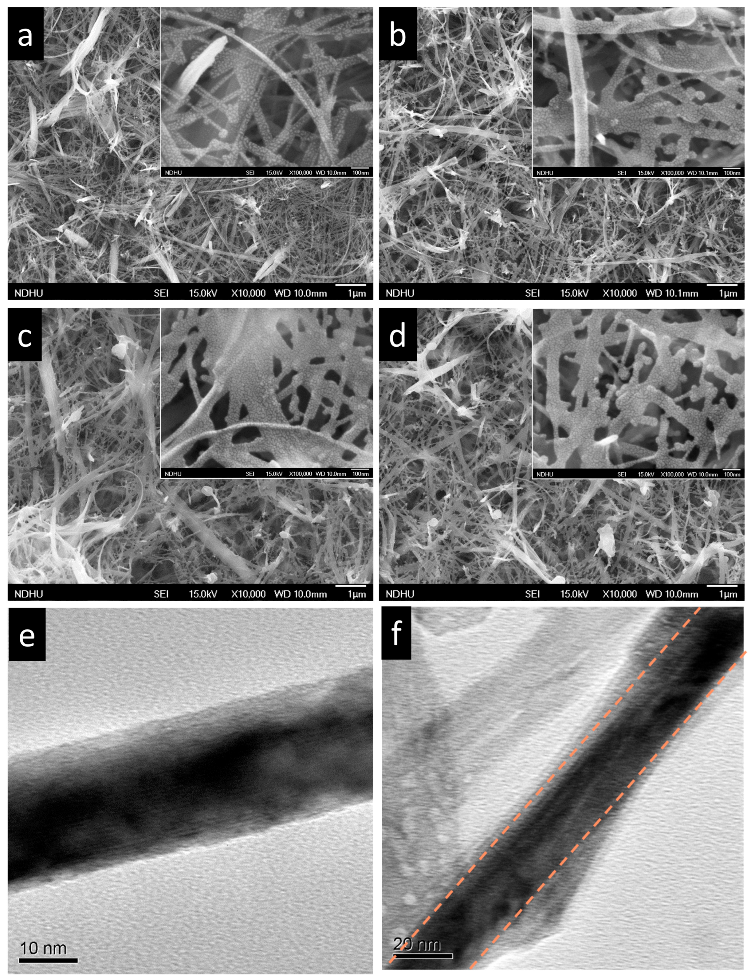
Figure 1. FESEM images of (a) pristine TiO2 NWs and InPOx/TiO2 NWs with InCl3 concentrations of (b) 0.05 M, (c) 0.1 M, and (d) 0.15 M. High-magnification SEM insets. TEM images of (e) pristine TiO2 NWs and (f) InPOx/TiO2 NWs with 0.1 M InCl3.
Molecules 30 03482 g001
Figure 2. (a) XRD patterns and (b) Raman spectra of InPOx/TiO2 NW samples with InCl3 concentrations of 0.05 M, 0.1 M and 0.15 M.
Molecules 30 03482 g002
Figure 3. (a) Ti 2p and (b) O 1s XPS spectra of pristine TiO2 NWs. (c) Ti 2p, (d) O 1s, (e) In 3d, and (f) P 2p of InPOx/TiO2 NWs with 0.1 M InCl3 concentration.
Molecules 30 03482 g003
Figure 4. Absorption spectra of pristine TiO2 and InPOx/TiO2 NWs with 0.1 M InCl3 concentration.
Molecules 30 03482 g004
Figure 5. (a) Linear sweep voltammetry under illumination of InPOx/TiO2 NWs with different InCl3 concentrations. (b) Band edge positions of amorphous InPO4 and TiO2. (c) IPCE and (d) injection efficiency of pristine TiO2 and InPOx/TiO2 samples with 0.1 M InCl3 concentration.
Molecules 30 03482 g005
Figure 6. (a) Nyquist plots and (b) Mott–Schottky plot of pristine TiO2 and InPOx/TiO2 samples. Stability test of (c) pristine TiO2 and (d) InPOx/TiO2 samples.
Molecules 30 03482 g006
Table 1. Comparison with studies regarding wide bandgap overlayer/TiO2 photoanode.
Material StructureNanocomposite Photocurrent Density (mA/cm2)BareTiO2 Photocurrent Density (mA/cm2)Current Density Gain RatioRef.
Au@CdS/RGO/TiO20.140.06133%[16]
Al2O3/TiO2~0.2~0.02900%[17]
ZnO/TiO22.370.68248%[18]
SrTiO3/TiO2~0.025~0.012108%[19]
SrTiO3/TiO23.481.5132%[20]
RGO/TiO22.451.9227%[21]
InPOx/TiO20.360.035928%This work
Disclaimer/Publisher’s Note: The statements, opinions and data contained in all publications are solely those of the individual author(s) and contributor(s) and not of MDPI and/or the editor(s). MDPI and/or the editor(s) disclaim responsibility for any injury to people or property resulting from any ideas, methods, instructions or products referred to in the content.