1. Introduction
Lithium-ion batteries (LIBs) garner extensive attention as energy storage devices, owing to their stable voltage platform and outstanding energy density [
1,
2]. However, the unsatisfactory discharge capacity, charging time, and cycle life of the graphite anode seriously limit the widespread application of LIBs [
3]. Therefore, substitutable anodes with higher structure stability and practical capacity have been widely sought after in the last few years [
4,
5]. TMDs generally have the advantages of higher theoretical capacity and lower reaction potential, which makes them a kind of anode material with excellent prospects for development. Among them, MoS
2 has received extensive attention from researchers as an anode material for lithium-ion batteries with prospects for industrial applications due to its high theoretical capacity (670 mA h g
−1) and simple preparation process. According to a previous report, the high capacity of MoS
2 is achieved via lithium-ion insertion (MoS
2 + xLi
+ + xe
− ↔ Li
xMoS
2) and conversion reaction (Li
xMoS
2 + (4 − x) Li
+ + (4 − x) e
− ↔ Mo + 2Li
2S) [
6]. The formation of Li
2S, however, results in the dissolution of Li
2S into the liquid electrolyte and disrupts the electrical contact between the TMDs and the current collector. Consequently, this phenomenon significantly compromises cycling stability and induces excessive capacity decay during cycling. The interstitial of the MoS
2 lattice can be adjusted via structural design and phase transition engineering to control the amount of lithium-ion insertion, thus realizing the purpose of controlling the capacity. Meanwhile, the good structural stability guarantees its stable lithium-ion storage performance [
7]. Therefore, MoS
2-based anodes attract significant attention for high-efficiency lithium-ion storage, with potential application prospects [
8]. However, the MoS
2-based anode still suffers from low electronic conductivity, unsatisfied lithium-ion transport kinetics, and large volume expansion. As a result, the MoS
2-based anode exhibits limited capability under the long-term charge/discharge process and rate capability. Moreover, the solid electrolyte interphase (SEI) film can give rise to “dead lithium” and unstable Coulombic efficiency (CE) [
9].
To address the above issues, morphological modification, structural optimization, and vacancy design are adopted [
10]. Jiao et al. reported an outer-wall-free hollow nanotube composed of intersecting small-sized MoS
2 nanosheets. The metal nanotubes are hierarchical, hollow, and have a porous arrangement, which aid electrolyte transport and diffusion, avoid the re-stacking of 2D nanosheets, and shorten the ionic diffusion path, thus maintaining the stability of electrochemical cycling and improving the rate performance [
11]. Chen et al. prepared nanoflowers crossed by MoS
2-MnS heterojunction nanosheets, confirming the phenomenon of sequential phase transition of MoS
2 and MnS in Li/Na storage, and electrochemical reaction kinetics and ex situ tests confirmed the roles of phase transition and interfacial engineering in the reaction [
8]. Bai et al. prepared 1T-MoS
2/C by hydrothermal reaction and confirmed that 1T phase-transformed MoS
2 has a high conductivity characteristic due to the nature of the metallic phase, which facilitates rapid transport of lithium ions and electrons and thus improves the electrochemical performance [
12]. However, the design reported above mainly focuses on the exterior morphology control, electrochemical conductivity, and reaction kinetics of the reported MoS
2 anode, which are inferior to those of the graphite anode, and the volume change is not fully released during the electrochemical reaction. It is unclear whether good adsorption ability toward lithium ions, good conductivity for charge transfer, and conversion kinetics are achieved simultaneously in those reported MoS
2 anodes. Moreover, the inadequate interfacial interaction in MoS
2-based anodes further influences the electrochemical conductivity and reaction kinetics [
13]. Therefore, the reported lithium-ion storage performance of MoS
2 anodes is inferior, and constructing a multi-advantage MoS
2 anode is highly required.
An interfacial engineering strategy is considered as an effective route to accelerate the charge transfer kinetics, adsorption, and intercalation ability of lithium-ion batteries via a strong interfacial bonding effect at the interface to achieve high-performance lithium-ion storage [
14,
15]. Moreover, the interfacial design can create sufficient active sites at the interface, which is significant for excellent lithium-ion storage capacity. However, an interfacial engineering strategy has rarely been reported to construct MoS
2 anodes, and the internal mechanism of interfacial interaction remains unclear. FeS
2 has the advantages of high chemical stability and high theoretical capacity (890 mA h g
−1), which makes it a satisfactory candidate for constructing MoS
2-based composites [
16]. Its incorporation enhances the stability of the material and improves the ionic conductivity and kinetic behavior of the MoS
2 anode. Sufficient interfacial contact between MoS
2 and FeS
2 would provide abundant interfacial sites to adsorb lithium ions. After the interfacial design, the interfacial region can adsorb a great deal of lithium ions and guarantee high electron transfer efficiency [
17]. As a result, the lithium-ion storage capacity and reaction kinetics of MoS
2/FeS
2 are prominently enhanced. However, constructing interfacial regions and enhancing the lithium-ion storage capacity of MoS
2/FeS
2 have seldom been researched so far.
Herein, phase transition engineering and interfacial engineering strategies are adopted to construct the MoS
2/FeS
2 anode. The interfacial covalent bond (Mo–S–Fe) is confirmed by TEM and XPS analyses. Enhanced pseudocapacitance contribution and improved charge transfer efficiency are further revealed by electrochemical kinetic analysis. Consequently, this well-designed MoS
2/FeS
2 anode demonstrates excellent cycling capacity, rate capability, and cycling life in half cells. This interfacial design strategy can enhance lithium-ion storage performance via the combined impact of surface sulfide and interfacial interaction, as well as provide a deeper understanding of re-designing traditional metal sulfide anodes [
18].
2. Results
MoS
2/FeS
2 nanoflower spheres are synthesized by a simple and low-cost hydrothermal reaction. More details about the synthetic process can be found in the Materials and Methods section. During the hydrothermal reaction, the transition from 2H-MoS
2 to 1T- MoS
2 in some MoS
2 is induced by a change in coordination modes between certain molybdenum and sulfur atoms. In
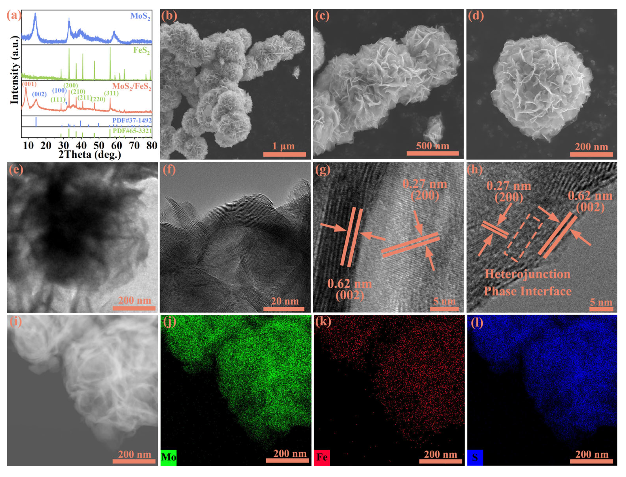
Figure 1a, the XRD results reveal that the diffraction peaks of pure MoS
2 correspond to MoS
2 (PDF#37-1492), and the diffraction peaks of pure FeS
2 correspond to FeS
2 (PDF#65-3321). For MoS
2/FeS
2, the characteristic peaks at 14.38°, 39.54°, and 49.79° correspond to the (002), (103), and (105) planes of MoS
2, and the characteristic peaks at 33.03°, 37.07°, 47.41°, and 56.26°correspond to the (200), (210), (220), and (311) planes of FeS
2. In addition to this, the diffraction peak appearing at about 9° is widely regarded as a characteristic peak of 1T-phase MoS
2, obtained by the transformation of part of the 2H-phase MoS
2 during heterojunction formation [
19,
20,
21]. The XRD results reveal that the hydrothermal reaction successfully constructed MoS
2/FeS
2 nanoparticles. SEM is performed to demonstrate the microstructure morphology before and after hydrothermal reaction (
Figure S1). The SEM results (
Figure 1b–d) confirm that the MoS
2/FeS
2 nanoflower spheres are composed of intercrossed small-sized nanosheets, with an average dimension of around 200 nm. The morphology of pure MoS
2 is irregular particles, and pure FeS
2 is a plate strip nanosheet (
Figure S2). The nanoflower spheres exhibit significantly enlarged specific surface area, facilitating the presence of more active sites and promoting the adsorption and rapid migration of lithium ions. Moreover, interlocking nanosheets contribute to maintaining the structural stability of the material. The rough surface of MoS
2/FeS
2 nanoflower spheres is confirmed, and the rough surface and stable chemical characteristics can improve the reversible conversion kinetics and lithium-ion adsorption capacity of MoS
2/FeS
2 anodes.
TEM is conducted to demonstrate the presence of an interfacial structure between MoS
2 and FeS
2. In
Figure 1e, the MoS
2/FeS
2 nanoflower spheres are clearly visible with irregular ball-like morphology in the low-magnification TEM image, and the rough surface is crucial for interfacial interaction and lithium-ion storage. The size of the grains measures approximately 200 nm, which aligns with the findings from
Figure 1d in the SEM analysis. In
Figure 1f, the presence of distinct boundaries between the MoS
2 and FeS
2 lattice fringes indicates simultaneous execution of the vulcanization process during hydrothermal reaction [
22]. As marked by the orange rectangular box, distinct heterointerface structure regions exist between MoS
2 and FeS
2, and this sufficient heterointerface structure shows efficient interatomic electron migration via a covalent chemical bond interaction to improve interfacial charge transfer kinetics and lithium-ion storage performance. The lattice spacing of about 0.27 nm in the figure is the (200) plane of FeS
2, and the lattice spacing of 0.62 nm is the (002) plane of MoS
2. The intact and distinct lattices both of MoS
2 and FeS
2 indicate that the crystallinity of MoS
2/FeS
2 obtained through hydrothermal reaction is excellent (
Figure 1g,h). The corresponding Selected Area Electron Diffraction (SAED) further proves the existence of MoS
2 and FeS
2 (
Figure S3). Thus, strong electrostatic attraction is formed via MoS
2, and FeS
2 is generated simultaneously after a hydrothermal reaction. The reconstructed interfacial layer can offer sufficient active reaction sites for lithium-ion adsorption, and it is beneficial for high electronic conductivity and fast electrochemical reaction kinetics [
23]. The elemental mapping analysis (
Figure 1i–l) shows the rectangular distribution of Mo (green), Fe (red), and S (blue) in MoS
2/FeS
2. The intimate contact interface between MoS
2 and FeS
2 significantly optimizes the lithium-ion transport path and enhances lithium-ion storage performance [
24].
The interfacial interaction and chemical composition of MoS
2/FeS
2, pure MoS
2, and FeS
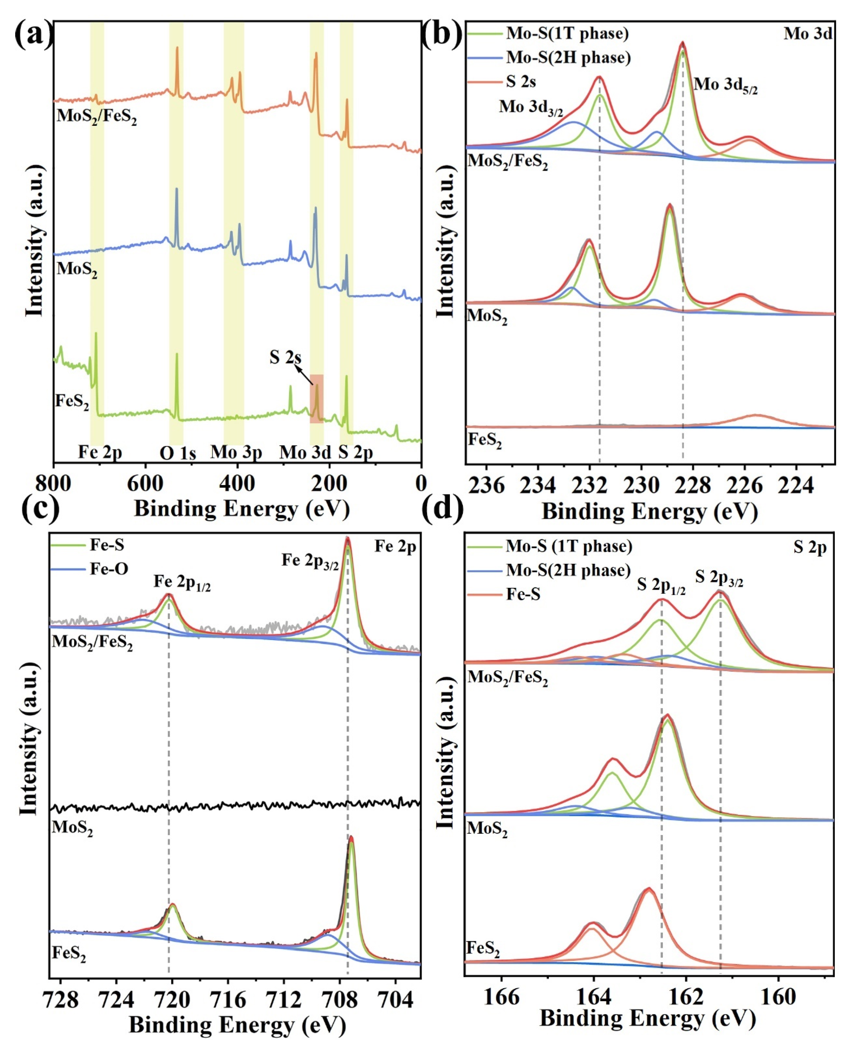
2 are further analyzed by XPS. Indeed, Mo 3d, Fe 2p, and S 2p are detected in the survey spectrum of MoS
2/FeS
2 (
Figure 2a). Only Mo 3d and S 2p are detected in the survey spectrum of MoS
2. Similarly, Mo 3d is not detected in the survey spectrum of FeS
2. For FeS
2, the peak at 225.6 eV in the survey spectrum is S 2s instead of Mo 3d [
25]. In
Figure 2b, the high-resolution Mo 3d spectra of MoS
2/FeS
2 show that the peaks at 228.4 and 231.6 eV belong to Mo 3d
5/2 and Mo 3d
3/2 of 1T-MoS
2, respectively, while the peaks in the 2H phase are located at 229.4 and 232.6 eV, respectively [
26]. Compared with pure MoS
2, the peak of MoS
2/FeS
2 is shifted toward low binding energy, and distinct electrostatic attraction is formed with the formation of an efficient electron transport path [
18]. The good electronic conductivity of MoS
2/FeS
2 is favorable for high reaction kinetics. Therefore, this result shows the evident chemical interaction and strong imbalanced charge distribution between MoS
2 and FeS
2, and the distinct interfacial contact provides sufficient interfacial sites for lithium-ion storage [
27]. The chemical state of Fe in MoS
2/FeS
2 is further analyzed. In
Figure 2c, the high-resolution Fe 2p spectrum can be deconvoluted to the Fe–S bond (Fe 2p
3/2 and Fe 2p
1/2) at 707.4 and 720.2 eV, respectively. In addition, the high-resolution Fe 2p spectrum also exhibits an obvious peak of Fe combined with O with the formation of a Fe–O bond at 709.2 and 722.2 eV, which is widely regarded as unavoidable oxidation of the lesser samples [
28]. Compared to MoS
2/FeS
2 with pure FeS
2, a higher binding energy shift for the Fe–S bond is clearly observed.
Similarly, the S 2p high-resolution spectrum of MoS
2/FeS
2 (
Figure 2d) exhibits two distinct sets of peaks associated with the Mo–S bond. Specifically, the peaks observed at 161.3 eV and 162.6 eV correspond to the 1T phase, while those detected at 162.4 eV and 164.0 eV are indicative of the presence of the 2H phase. In addition, the remaining set of peaks belonging to Fe–S can be deconvoluted to 163.4 eV and 164.4 eV, respectively. Compared with pure MoS
2 and pure FeS
2, all the peaks corresponding to Mo–S bonds move to the direction of low binding energy, while all the peaks corresponding to Fe–S bonds move to the direction of high binding energy, and this phenomenon fully confirms the process of electron transfer from FeS
2 to MoS
2. Widespread Mo–S bonds and Fe–S in MoS
2/FeS
2 provide good electron conductivity and Faradaic pseudocapacitance. Furthermore, the heterogeneous interface leads to a lopsided charge distribution near the interface, and the corresponding interfacial interaction can boost the electron transfer reactions and offer sufficient active reaction sites for lithium-ion storage. The changes in the Mo–S and Fe–S binding energies demonstrate the interaction between MoS
2 and FeS
2, which further enhances the adsorption of lithium ions at the interface. Therefore, the XPS analysis confirms that MoS
2 and FeS
2 were formed synchronously during the hydrothermal reaction. The imbalanced charge distribution occurring in the interfacial region can create an inner electric field [
29], and the partial phase transition produces 1T-MoS
2 with metallic conductor properties favoring the electronic conductivity of the MoS
2/FeS
2. Moreover, the heterogeneous interface demonstrates strong covalent chemical bond interaction between the MoS
2 layer and FeS
2 layer, which is important for interfacial lithium-ion storage. The XPS analysis unambiguously shows that heterogeneous interfaces are formed through the simultaneous generation of the hydrothermal reaction MoS
2 and FeS
2 and that heterogeneous interfaces enhance interfacial charge migration for lithium-ion storage.
The lithium-ion storage performance of the MoS
2/FeS
2 anode is evaluated by standard half-cell tests. As shown in
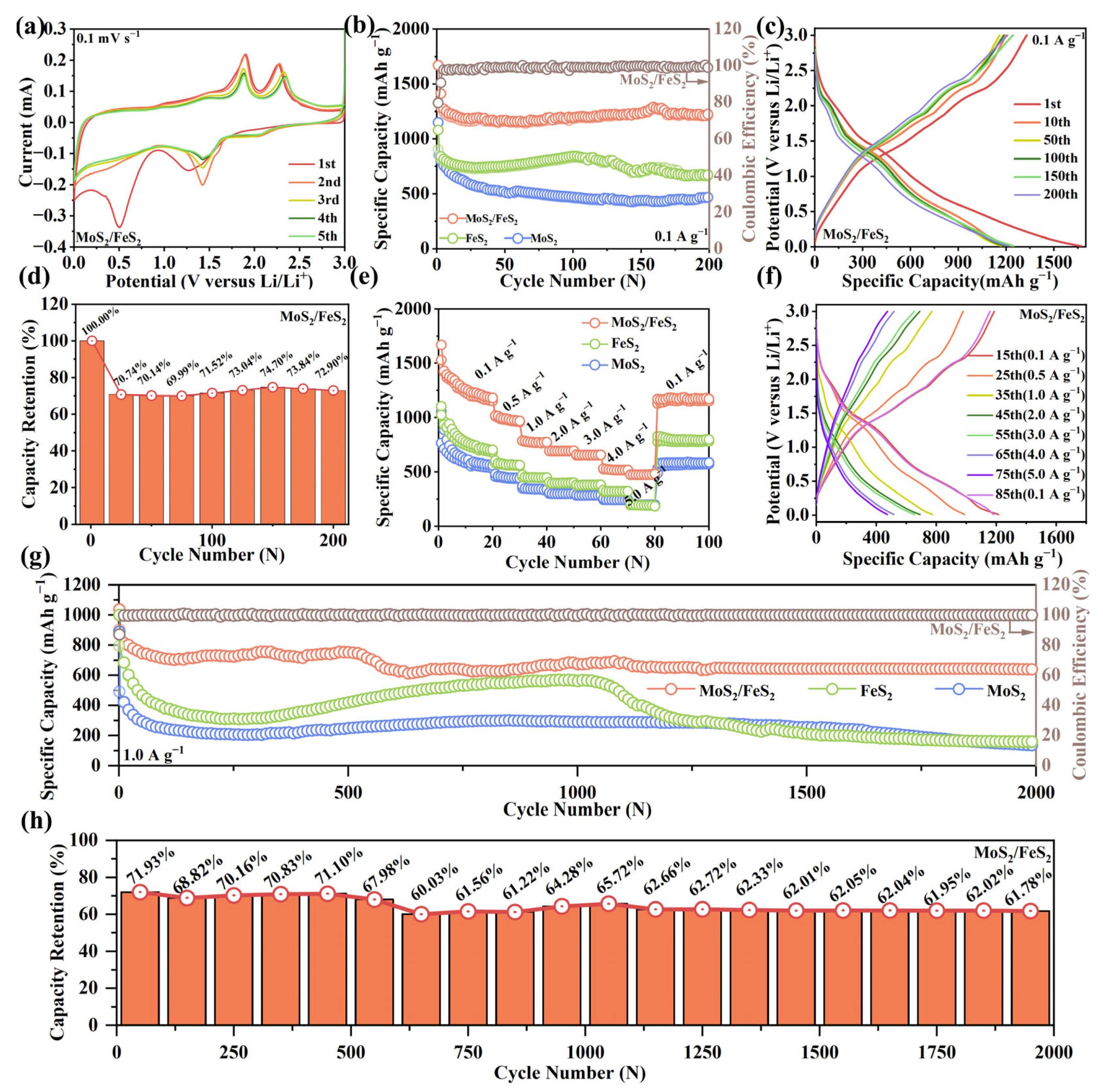
Figure 3a, the MoS
2/FeS
2 anode can be clearly observed within the circle of the first cycle curve. There are two reduction peaks at 0.50 V and 1.26 V, which correspond to the formation of the SEI layer and the conversion of MoS
2/FeS
2 to Mo, Fe, and Li
2S, respectively. In the next cycle, the reduction peak moves to around 1.42 V, and a new peak appears at 2.05 V due to the irreversible phase transition formed by S and Li
2S. There is an oxidation peak at 1.81 V, which corresponds to the reaction of, Mo, Fe, and Li
2S to form Li
xMoS
2 and Li
xFeS
2. There is another oxidation peak at 2.28 V, corresponding to the decomposition of Li
xMoS
2 and Li
xFeS
2 to MoS
2 and FeS
2. As the cycle progresses, the oxidation peak located at 2.28 V undergoes a small shift towards higher voltages. This phenomenon is thought to result from the potential deviation from the equilibrium potential caused by irreversible resistance [
30]. The reduction peak at 0.50 V fades away in the next cycle due to the SEI layer forming an anodic surface coating, and the other peaks do not change much, indicating good electrochemical reversibility. The overlapped CV curves imply its outstanding structure and cycling stability. This result is related to efficient covalent bond interaction at the interface of MoS
2/FeS
2.
Figure 3b shows the cycling performance and Coulombic efficiency of MoS
2/FeS
2, pure MoS
2, and FeS
2 at 0.1 A g
−1. For MoS
2/FeS
2, the first discharge-specific capacity is about 1670.6 mA h g
−1, and the initial Coulombic efficiency (ICE) is ~79.63%. In comparison, the ICE of MoS
2 is only 73.99%, with a first discharge-specific capacity of 1151.3 mA h g
−1, and an ICE of FeS
2 (81.65%); although slightly higher than that of MoS
2/FeS
2, it has a first discharge-specific capacity of only 1080.9 mA h g
−1. Unlike conventional conversion reaction anodes with major structure invalidation and capacity loss, the interfacial engineering strategy can accelerate charge transfer kinetics, adsorption, and intercalation ability. For the MoS
2/FeS
2 anode, the discharge capacity can stabilize at 1217.8 mA h g
−1, and the Coulombic efficiency can be maintained at about 100% after 200 cycles. In contrast, the discharge capacity of the MoS
2 negative electrode decreased continuously at a current density of 0.1 A g
−1 and was only 463.1 mA h g
−1 after 200 cycles. Although the discharge capacity of the FeS
2 negative electrode recovered during the cycling process, it still decreased to 672.3 mA h g
−1 after 200 cycles, which was much lower than that of the MoS
2/FeS
2 negative electrode. In
Figure 3c, the GCD curves show superior electrochemical stability and minimum polarization of the MoS
2/FeS
2 anode compared to the pure MoS
2 and FeS
2 anodes (
Figure S4). This is ascribed to the enhanced interfacial interaction and efficient interatomic electron migration caused by distinct heterointerface structures and covalent chemical bond design [
31]. In
Figure 3d, the trend regarding discharge capacity change is precisely analyzed by capacity retention. Selecting the first discharge capacity as a check, the discharge capacity retentions of the MoS
2/FeS
2 anode are calculated. Meanwhile, the discharge capacity retentions of the pure MoS
2 and FeS
2 anodes are also calculated (
Figure S5). After 200 cycles, the capacity retention rate of the MoS
2/FeS
2 anode is 72.9%, which is much higher than the capacity retention rate of 40.22% for the MoS
2 anode and 62.2% for the FeS
2 anode. By comparison, the MoS
2/FeS
2 anode exhibits higher and stabler capacity retention, which indicates a more stable lithium-ion storage reaction.
In
Figure 3e, the rate capability values of the pure MoS
2, FeS
2, and MoS
2/FeS
2 anodes are further analyzed from 0.1 to 5.0 A g
−1. For the MoS
2/FeS
2 anode, reversible capacity of 1180.2, 967.3, 773.6, 694.3, 656.5, and 517.1 mA h g
−1 can be achieved at 0.1, 0.5, 1.0, 2.0, 3.0, and 4.0 A g
−1, respectively. Notably, even at 5.0 A g
−1, the discharge capacity can be maintained at 480.9 mA h g
−1. At 0.1 A g
−1, the discharge capacity can return to 1169.5 mA h g
−1 after 80 cycles, showing good structural tolerance and electrochemical reversibility. Rate capability analysis shows good lithium-ion adsorption and diffusion kinetics of the MoS
2/FeS
2 anode. In addition, the rate capability values of the pure MoS
2 and FeS
2 anodes are much inferior to that of the MoS
2/FeS
2 anode. This result can be ascribed to the decomposition of the irreversible electrolytes at low potential and volume expansion during the repeated lithium-ion storage reaction. The excellent reversibility of the half cell is further confirmed by the corresponding GCD curves at different current densities in
Figure 3f. The enhanced electronic conductivity and lithium-ion transfer kinetics contribute to its remarkable rate capability.
In
Figure 3g, the long cycling capacity is further evaluated at 1.0 A g
−1. The pure MoS
2 anode shows the highest discharge capacity as the first cycle progresses, and then the discharge capacity starts to decline. For pure FeS
2, the discharge capacity reduces to 136.6 mA h g
−1 after 2000 cycles. For FeS
2, the discharge capacity of 1000.5 mA h g
−1 for the first cycle is essentially the same as that of MoS
2/FeS
2, but the capacity decays rapidly as the cycle progresses. Although the discharge capacity rebounded at 500–1000 cycles, it slowly decayed in the subsequent cycles and dropped to 158.6 mA h g
−1 after 2000 cycles. Compared with pure MoS
2 and FeS
2 anodes, the MoS
2/FeS
2 anode displays outstanding cycle durability at 1.0 A g
−1. For the MoS
2/FeS
2 anode, the first discharge capacity is about 1037.2 mA h g
−1, and the first charge capacity is 903.7 mA h g
−1, with a high ICE of 87.13%, which is much higher than that of 55.31% for the MoS
2 anode and 79.47% for the FeS
2 anode. The discharge capacity is maintained at 638.9 mA h g
−1, and the Coulombic efficiency stabilizes at about 100% after 2000 cycles. In
Figure 3h, capacity retention analysis is performed to refine the discharge capacity fluctuation of the MoS
2/FeS
2 anode, and the capacity retention analysis of the pure MoS
2 and FeS
2 anodes is also calculated (
Figure S6). At a current density of 1.0 A g
−1, the capacity retention of MoS
2/FeS
2 is at a high level, and, after nearly 2000 cycles, the capacity retention of MoS
2/FeS
2 is still 61.78%. The capacity retention of MoS
2 and FeS
2 stays at a low level, 16.33% and 15.89%, respectively, after nearly 2000 cycles. Compared with the pure MoS
2 and FeS
2 anodes, the cycling durability of MoS
2/FeS
2 is the highest. The good capacity retention of the MoS
2/FeS
2 anode is ascribed to the distinct heterointerface structural design between MoS
2 and FeS
2, and the sufficient heterointerface structure can enhance interatomic electron migration with abundant active sites via covalent chemical bond interaction to improve interfacial charge transfer kinetics. Obviously, the MoS
2/FeS
2 anode shows its high-efficiency interfacial interaction and lithium-ion storage performance for potential application.
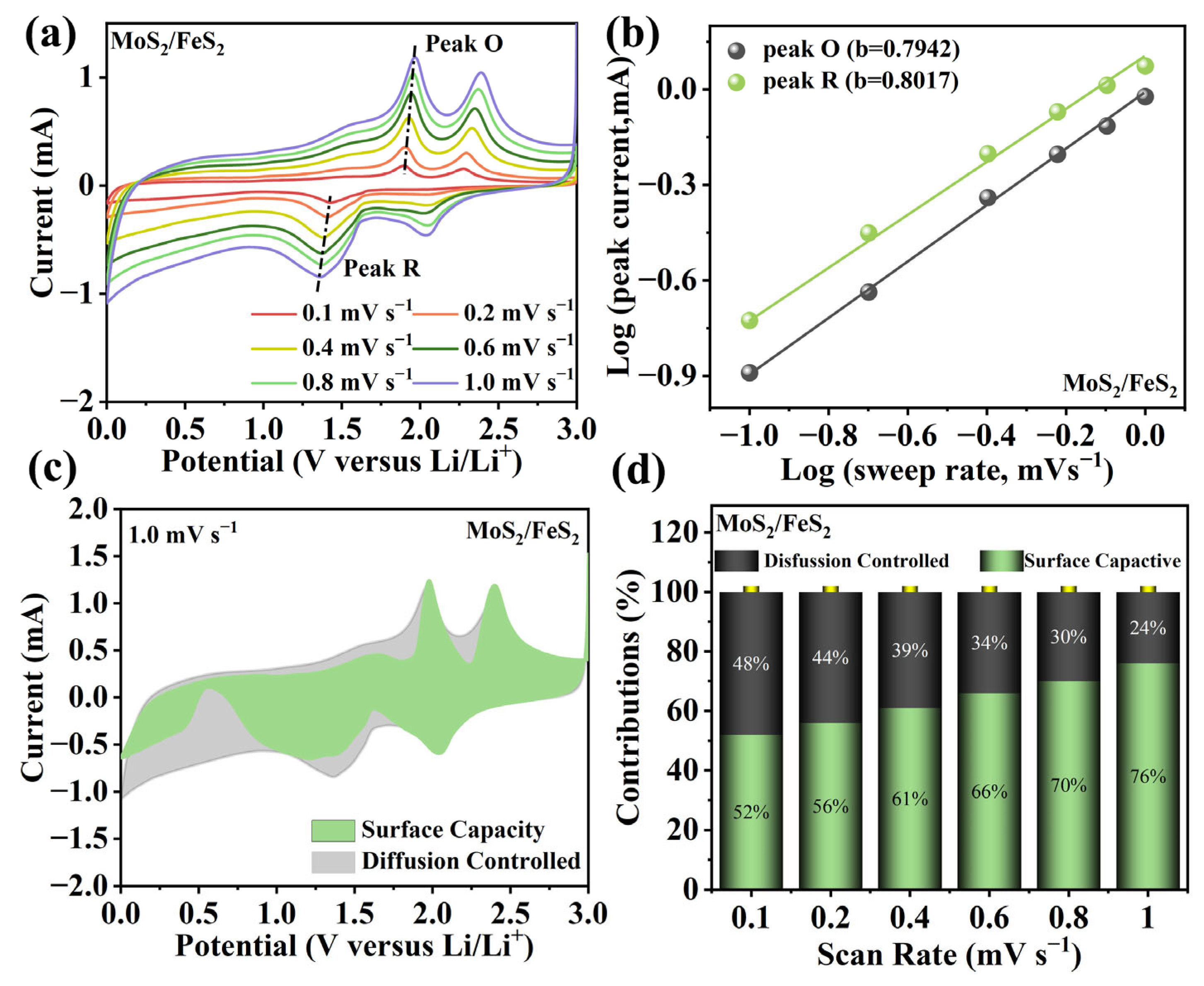
With the scan rate increasing, the oxidation and reduction peaks shift slightly (
Figure 4a). The lithium-ion storage capacity is usually composed of diffusion capacity and surface capacity [
32]. Meanwhile, qualitative analysis of diffusion capacity and surface capacity can be performed via the following equation:
where
a is an adjustable parameter, and the current (
i) is calculated via the law relationship of sweep rate (
v) [
33]. The
b-value is the slope of log(
i) versus log(
v), which is used to distinguish diffusion capacity (
b = 0.5) and surface capacity (
b = 1.0) [
34]. In
Figure 4b, they are calculated to be 0.7942 and 0.8017, showing the coexistence of diffusion capacity and surface capacity in the MoS
2/FeS
2 anode. Quantitative analysis of diffusion capacity and surface capacity can be obtained via the following equation [
35]:
At specific potential (
V), the current (
i) can be separated as surface capacity (
k1v) and diffusion capacity (
k2v1/2) [
36]. In
Figure 4c, the pseudocapacitance of the MoS
2/FeS
2 anode is as high as 76% at 1.0 mV s
−1. It is clear that pseudocapacitive behavior dominates the electrochemical processes in the MoS
2/FeS
2 heterojunction anode. The distinguished diffusion capacity and surface capacity are shown in
Figure 4d. It can be observed that the surface capacity gradually improves, showing the higher surface capacity at high current density. At 0.1 mV s
−1, the surface capacity is still higher than 50%, resulting in enhanced electrochemical kinetics and excellent rate capability. This pseudocapacitance analysis shows sufficient lithium-ion adsorption in MoS
2/FeS
2. Moreover, electrochemical impedance spectra (EIS) analysis is conducted to show the advanced lithium-ion reaction kinetics in the MoS
2/FeS
2 anode. In
Figure S7, MoS
2/FeS
2 and pure MoS
2 and FeS
2 anodes have similar EIS curves, which are constituted of a semicircle at medium–high frequency (
Rct) and an inclined line at low frequency (
Rw). By comparison, the MoS
2/FeS
2 anode exhibits lower charge transfer resistance (
Rct = 80.6 Ω) and lithium-ion transfer resistance than those of the pure MoS
2 anode (
Rct = 253.4 Ω) and the FeS
2 anode (
Rct = 335.9 Ω). This suggests that the heterogeneous interface constructed by the in situ hybridization strategy provides low internal resistance and strong lithium-ion migration capability to the MoS
2/FeS
2 anode. The improved electrochemical kinetics can be ascribed to the sufficient active sites and the intimate covalent chemical bond interaction.


