Review

Progress in Promising Semiconductor Materials for Efficient Photoelectrocatalytic Hydrogen Production

by
Weisong Fu
1,
Yan Zhang
1,
Xi Zhang
1,
Hui Yang
2,*,
Ruihao Xie
1,
Shaoan Zhang
1,
Yang Lv
1 and
Liangbin Xiong
1,*
1
School of Optoelectronic Engineering, Guangdong Polytechnic Normal University, Guangzhou 510665, China
2
School of Medical Information Engineering, Gannan Medical University, Ganzhou 341004, China
*
Authors to whom correspondence should be addressed.
Molecules 2024, 29(2), 289; https://doi.org/10.3390/molecules29020289
Submission received: 25 November 2023 / Revised: 17 December 2023 / Accepted: 2 January 2024 / Published: 5 January 2024
(This article belongs to the Special Issue Electroanalysis of Biochemistry and Material Chemistry)

Abstract

:
Photoelectrocatalytic (PEC) water decomposition provides a promising method for converting solar energy into green hydrogen energy. Indeed, significant advances and improvements have been made in various fundamental aspects for cutting-edge applications, such as water splitting and hydrogen production. However, the fairly low PEC efficiency of water decomposition by a semiconductor photoelectrode and photocorrosion seriously restrict the practical application of photoelectrochemistry. In this review, the mechanisms of PEC water decomposition are first introduced to provide a solid understanding of the PEC process and ensure that this review is accessible to a wide range of readers. Afterwards, notable achievements to date are outlined, and unique approaches involving promising semiconductor materials for efficient PEC hydrogen production, including metal oxide, sulfide, and graphite-phase carbon nitride, are described. Finally, four strategies which can effectively improve the hydrogen production rate—morphological control, doping, heterojunction, and surface modification—are discussed.

1. Introduction

Hydrogen is known as the 21st century’s most promising clean energy due to its status as an efficient energy carrier with a high energy combustion value (142.5 kJ/g), and the end product of its use is water [1,2]. To some extent, the development and utilization of hydrogen energy in relation to renewable energy sources has alleviated the fossil energy crisis [3,4]. Solar energy is inexhaustible but inconveniently used due to its dispersion. In this case, converting solar energy into hydrogen energy is a very promising energy solution because it can be more easily stored and effectively used [5,6].
Photoelectrocatalytic (PEC) hydrogen evolution using semiconductor photoelectrodes under irradiation has been widely studied as one of the effective ways to convert solar energy into hydrogen energy [7,8]. TiO2 has been one of the most important and frequently studied PEC photoelectrodes since the discovery of the Fujishima–Honda effect [9]. After decades of development, PEC photoelectrodes have sufficiently expanded to a variety of TiO2-based and other new photoelectrode materials; the influence of these photoelectrodes on PEC hydrogen production has been widely studied, and the related mechanisms have been exhaustively discussed [10,11,12].
The purpose of this review is to consider the progress on photoelectrocatalysis (PECs) for hydrogen generation from water using high-performance photoelectrode materials. In particular, this work considers the key material properties of photoelectrodes and the trends in research focused on the development of photoelectrodes that may bring PEC technology to commercial maturity. We focus on the preparation and modification of semiconductor photoelectrode materials that have been widely investigated by researchers. Various high-performance photoelectrode materials, including metal oxide, sulfide, and graphitic carbon nitride semiconductors, are discussed. Numerous considerations are limited solely to oxide materials, which appear to exhibit superior properties as photoelectrodes in comparison to other types of materials.

2. The PEC Process of Water Decomposition

2.1. Mechanisms

PECs combines the advantages of both photocatalytic and electrocatalytic technologies. PECs can both make use of solar energy and regulate the photocatalytic process by using photoelectrodes with an appropriate external bias. Moreover, photoelectrodes are convenient for recycling in PEC processes, avoiding the dilemma encountered in the photocatalytic process.
When a semiconductor (e.g., photoanode) is irradiated, electrons and holes can be formed in the conduction band and the valence band, respectively. An electric field at the electrode/electrolyte interface is required in order to avoid the recombination of these charge carriers. The electrons generated in the photoanode are transferred over the external circuit to the cathode, resulting in a reduction reaction (for example, hydrogen ions are reduced into gaseous hydrogen). The light-induced holes lead to the splitting of water molecules into gaseous oxygen and hydrogen ions. The overall reaction for the PEC process may be expressed in the following form:
2 h ν + H 2 O 1 2 O 2 ( g a s ) + H 2 ( g a s ) .
Reaction (1) takes place through a high energy barrier with a Gibbs free energy value of 237.2 kJ/mol, and the electrochemical decomposition of water is possible when the electromotive force of the cell is equal to or larger than 1.23 eV [13].
Concerning the mechanisms of the reactions, the principle of PEC water decomposition is highly related to the energy band structure of the photoelectrode semiconductor. Figure 1 shows a schematic diagram of a typical semiconductor energy band structure, illustrating the various band levels of established electrodes and comparing them with the potentials corresponding to H2/H+ and H2O/O2 redox couples. The bandgap of the photoelectrode semiconductor should be greater than 1.23 eV for the overall reaction for PEC water decomposition. Meanwhile, the conduction band of the semiconductor should be more negative than the electrode potential of H2/H+, while the valence band position should be more positive than the electrode potential of H2O/O2 for the complete decomposition of water. Moreover, the water decomposition voltage is frequently higher than the theoretical value of 1.23 V [14] due to the existence of overpotential in practical PEC systems. It is well known that most semiconductors can satisfy only one of these conditions [15]. Figure 1 shows the band structures of some semiconductors.
In addition, the hydrogen half-reaction involves the transfer of only two electrons, whereas the half-reaction of oxygen production requires the transfer of four electrons and the formation of O-O bonds. Therefore, the generation of hydrogen is thermodynamically favorable, and the oxygenation reaction is the bottleneck of the whole reaction process if one takes into account the slowest process that determines the overall rate [17].

2.2. PEC Cell

Generally, the PEC cell is composed of a photoelectrode, counter electrode, reference electrode, and electrolyte solution. The photoelectrode, used as the working electrode, is mainly composed of a conductive substrate and a semiconductor film material. N- and p-type semiconductors are generally used as photoanodes for PEC oxygen production and photocathodes for PEC hydrogen evolution, respectively.
Materials with good charge collection performance and low reaction overpotential, such as platinum counter electrodes, are usually selected to fulfil the role of the counter electrode.
The electrolyte solution is responsible for mass transfer in the PEC cell. Therefore, the electrolyte solution should have a high conductivity. Salt substances such as Na2SO4 and K2SO4 are commonly used in neutral electrolyte solution, while acidic and alkaline solutions, as well as buffer solution, are employed for specific experimental conditions.
PEC cells can be divided into PEC photoanode cells, PEC photocathode cells, and PEC tandem cells, depending on the way that the semiconductor photoelectrodes are arranged. The PEC photoanode cell generally takes a n-type semiconductor as the working electrode and a platinum electrode as the counter electrode. The PEC photocathode cell often uses a p-type semiconductor as the working electrode and a platinum electrode as the counter electrode. The configuration of the PEC tandem cell is depicted in Figure 2, where a n-type and a p-type semiconductor are used as a photoanode and photocathode, respectively. The first two kinds of cells, using a single semiconductor as a working electrode, frequently require an external bias to promote the decomposition of water [16]. Fortunately, in a PEC tandem cell, the combination of a photoanode and photocathode is highly possible to ensure the complete photosplitting of water under sunlight without bias. As shown in Figure 2, photoanode and photocathode materials with different light absorption ranges can broaden the spectral range in the PEC tandem cell. The configuration of the PEC tandem cell is helpful for increasing photocurrent density and improving the efficiency of solar water splitting [18,19].

3. Semiconductor Materials for PECs

In 1972, Fujishima Akira et al. [9] first reported the successful PEC decomposition of water on the surface of TiO2 single-crystal electrodes under UV irradiation. Subsequently, researchers around the world observed a similar phenomenon of PEC hydrogen production on other semiconductor materials, such as BiVO4 [21,22], Cu2O [23,24], Fe2O3 [25,26], WO3 [27,28], and ZnO [29,30]. After decades of development, PEC hydrogen evolution using semiconductor photoelectrodes has made great progress.

3.1. Metal Oxide Materials

Currently, metal oxide semiconductors are considered for their advantages in terms of photochemical stability, their low cost, and their suitability for large-scale preparation [31,32,33]. TiO2 has been widely studied due to its excellent photocatalytic activity, stability, safety, non-toxicity, rich content, and ease of preparation. However, TiO2 with a wide bandgap of 3.2 eV can only be activated by UV light with a wavelength below 387 nm. Thus, many efforts have been taken to improve the PEC efficiency of TiO2. For example, the visible light activity of TiO2 can be enhanced by modification. In particular, in the late 1980s, researchers devoted their efforts to developing second-generation TiO2 that could absorb both UV (290–400 nm) and visible (400–700 nm) light and thereby enhance the overall efficiency. N-type BiVO4 [34] and p-type Cu2O [35] are widely regarded as promising semiconductor materials for efficient PEC hydrogen production due to their bandgap widths and suitable band structures.

3.1.1. TiO2

TiO2, possessing excellent photoelectric performance and high photochemical stability, has always been a very promising PEC material. However, as mentioned above, TiO2 can only absorb UV light, and the photogenerated charges are easy to recombine, resulting in a low PEC efficiency. Fortunately, the PEC efficiency of TiO2 can be effectively improved by doping and constructing composite structures.
(1)
Doping
Gong [36] and co-workers reported a tungsten-doped TiO2 nanotube arrays (W-TiO2 NTs) photoelectrode with an exclusive anatase phase utilizing a facile and novel anodization process on a Ti sheet. The results showed that W atoms were successfully incorporated into the TiO2 lattice in the form of W6+ ions, which did not influence the morphologies of the TiO2 NTs samples. The samples were evaluated by XPS to analyze the chemical states of W in W-TiO2 NTs. The peaks of C1s, O1s, Ti3p, Ti2p, and W4f were observed, as shown in Figure 3A. Figure 3B clearly shows that the peak of Ti3p shifted from 35.9 to 36.9 eV because of the presence of W in the TiO2 lattice. Thus, the W6+ ions were loaded into the bulk TiO2 lattice by displacing Ti4+ ions and forming W-O-Ti bonds. As shown in Figure 4, the highest photocurrent density and hydrogen production rate were observed for the 15 mM W-TiO2 NTs annealed at 400 °C. Under illumination, the photocurrent density quickly reached a constant value of 0.3 mA/cm2, which indicates that the transfer of the photogenerated charge is quite rapid. The photocurrent pattern is highly reproducible for several on–off light cycles. The photogenerated electrons are rapidly transported from the TiO2 nanotube arrays to the counter electrode to produce the photocurrent [37].
The PEC performance of TiO2 can also be improved by metal element doping to increase its conductivity. A simple saturated aqueous solution method was used to synthesize a novel rutile Nb-TiO2/g-C3N4 photoanode, whose photocurrent was 1.39 times larger than that of its pristine counterparts under UV light [38]. In addition, the unoccupied conduction band of TiO2 comprises Ti3d, 4s, 4p orbitals, whereas the occupied valence band (VB) comprises O2p orbitals. Ti3d orbitals dominate in the lower position of the conduction band [39,40]. An impurity level can be induced by doping with other metal ions (cations) in place of Ti. The resultant intermediate energy level promotes visible light absorption by acting as either an electron donor or acceptor. By doping Fe into TiO2, the absorption peak of the sample can gradually shift to red with the increase in the amount of Fe3+ loading, as shown in Figure 5A. The red shift of the absorption edge in Fe/TiO2 might be attributed to the excitation of 3d electrons of Fe3+ ions to the TiO2 conduction band (charge transfer transition) [41]. Figure 5B shows that the hydrogen evolution rate reached the maximum in the 1.0 wt% Fe/TiO2 photocatalyst. Meanwhile, the H2 evolution rate decreased in the 2.0 wt% Fe/TiO2 photocatalyst, which might be due to the role of excess Fe3+ as a recombination site. Compared with the W-TiO2 NTs mentioned above, the hydrogen production rate was reduced because more energetic ultraviolet light below 400 nm is shielded. However, its response to visible light makes Fe/TiO2 more widely used.
(2)
TiO2-based composites
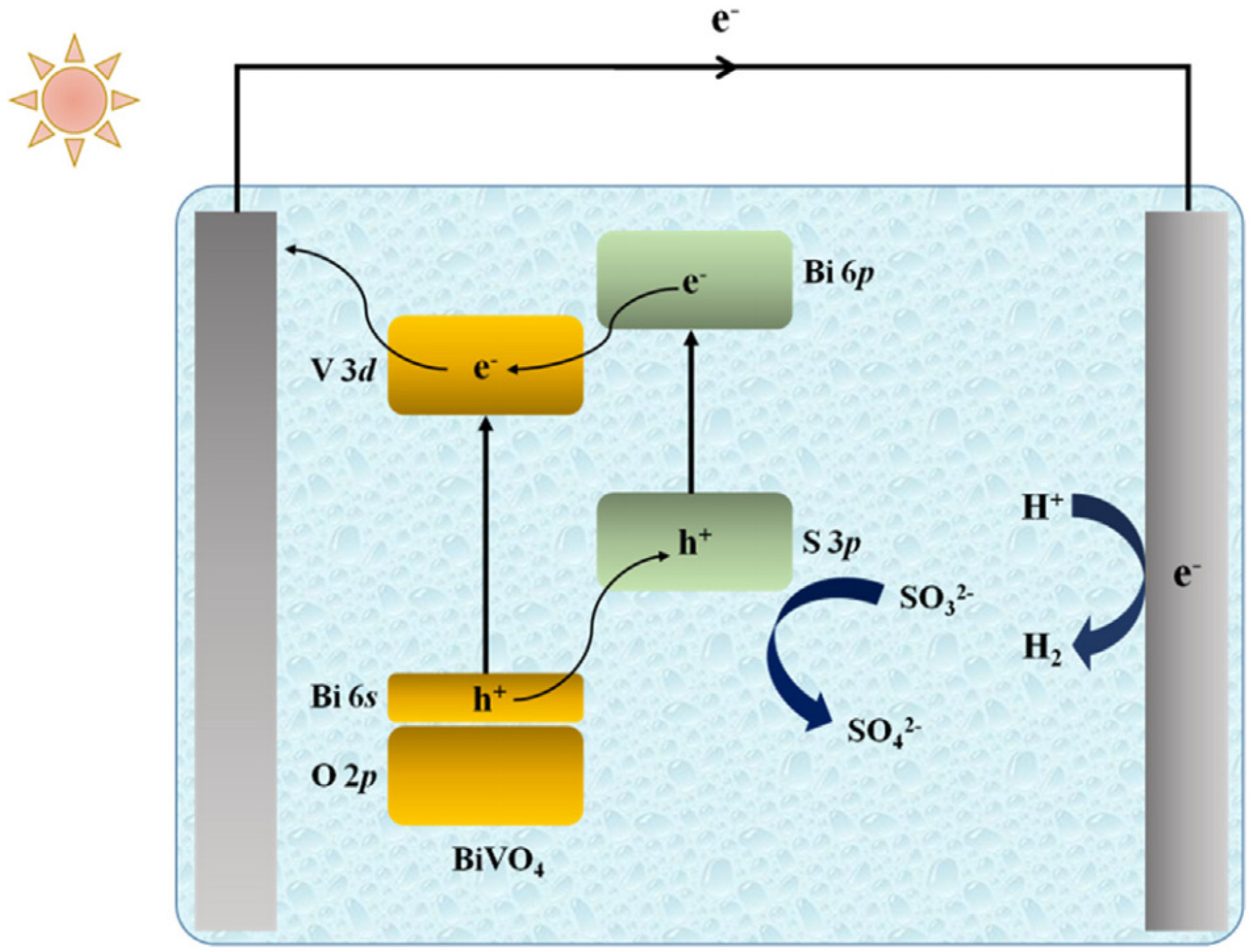
Liu [42] and co-workers reported a TiO2 NTs/Bi2MoO6 type-II heterojunction (a detailed description of type-II heterojunctions is available in Section 3.3) photocatalyst prepared using a simple solvothermal method. Bi2MoO6 nanoparticles (NPs) with nanosheet microstructures were successfully loaded on the surface of TiO2 NTs through the adjustment of reaction intervals. With increasing reaction time, the amount of Bi2MoO6 deposition increased gradually. The absorption edges of the samples with reaction times of 14, 18, 22, and 26 h were located at 380, 414, 495, and 452 nm, respectively (Figure 6a). Furthermore, the band gaps of the samples could be estimated using transformational Tauc plots, and their band gaps were calculated to be 3.2, 2.9, 2.4, and 2.7 Ev (Figure 6b). Reductions in band gap values were beneficial to solar energy absorption and photoelectric performance. Because the CB and VB position of Bi2MoO6 are more negative than TiO2, a type-II heterojunction can be formed at the interface of TiO2 NTs/Bi2MoO6. As shown in Figure 7, the electrons in the VB of the composite material are motivated by photon energy and jump to the CB. Then, electrons in the Bi2MoO6 CB transfer to that of TiO2, and the holes in the TiO2 VB transfer to the Bi2MoO6 VB via the assistance of the internal electric field of the type-II heterojunction. This structure greatly suppresses the recombination of photogenerated electron–hole pairs.
Adamopoulos [43] and co-workers reported a photoanode which was made by depositing, on FTO electrodes, either a nanoparticulate WO3 film alone or a bilayer film made of nanoparticulate WO3 at the bottom, covered with a nanoparticulate TiO2 film on the top. Due to the scattering of light by the top TiO2 layer, the photocurrent increased by enhancing the light absorption by WO3, as shown in Figure 8.
Our research group and a few others developed several TiO2-based composite systems for energy storage, such as TiO2/WO3 [44,45], TiO2/MoO3 [46], and TiO2/Ni(OH)2 [47]. The energy can be stored either in reduced WO3, MoO3, or in oxidized Ni(OH)2 under UV-light irradiation. In 2008, Yasomanee et al. [48] reported that a TiO2/Cu2O film photoelectrode led to the continuous generation of H2 from water splitting in the dark after UV–vis light irradiation stopped. The following year, we demonstrated that Ti3+ in a TiO2/Cu2O bilayer film has energy storage ability under visible light irradiation. We observed that H2 evolution was still noticeable after the irradiation stopped until the third hour. We believe that the electrons trapped in Ti3+ ions as stored energy lead to the evolution of H2 from H2O in the dark [49]. As shown in Figure 9, the photoelectrons of Cu2O were captured by Ti4+ ions in TiO2, resulting in the reduction of Ti4+ ions to Ti3+ ions. The electrons trapped in Ti3+ ions would have been released if suitable electron acceptors existed. Two years later, we [50] also found that the TiO2/Cu2O composite is capable of both organic degradation and photocatalytic H2 evolution under visible light. Different from the two TiO2 composites mentioned above, the TiO2 layer here also plays a protective role for the Cu2O layer. It is well known that Cu2O is highly susceptible to photocorrosion. The existence of the TiO2 protective layer improves the stability of the photocatalyst.

3.1.2. BiVO4

BiVO4 is considered as one of the most promising materials in the field of PEC water decomposition thanks to its visible light response, good stability, safety, and non-toxicity. In 1998, Kudo et al. [51] first reported that BiVO4 powder can be used as a photocatalyst to decompose water under visible light. Five years later, Sayama et al. [52] first demonstrated that a BiVO4-based photoanode successfully decomposed water into hydrogen and oxygen gas.
(1)
Doping
At present, BiVO4 photoanodes are mainly prepared by coating and electrodeposition. Firstly, a precursor solution containing Bi, V, or other impurity elements are prepared for the deposition of BiVO4 films; secondly, the precursor solution is coated on the conductive substrate (FTO or ITO) by spin-coating, dip-coating, spraying, or scraping technology; finally, BiVO4 film photoanodes can be obtained by post-annealing [53,54]. The preparation process is convenient for regulating the composition of the film, contributing to a suitable way to study the effect of doping on a BiVO4 film. Luo et al. [55] examined the PEC performance of BiVO4 photoanodes doped with 11 different kinds of elements through the above process. They found that the PEC performances of the BiVO4 photoanodes significantly improved after they were doped with W or Mo. Abdi et al. [56] found that the charge separation efficiency values of the BiVO4 photoelectrodes significantly improved as the content of W in the precursor ranged from 0% to 1%.
Kim [57] and co-workers used dimethyl sulfoxide with low hydrophilicity to dissolve acetylace to phenoxy vanadium as a vanadium source solution before coating it on the surface of BiOI thin film electrodes. The problem regarding the poor infiltration of ammonia solution and the BiOI film was solved by this step. Crucially, Kim et al. subjected nanoporous BiVO4 to a mild annealing treatment under N2 flow, which resulted in nitrogen being incorporated into the oxygen sites. The bandgap of the sample was reduced, while the carrier mobility was increased.
(2)
BiVO4-based composites
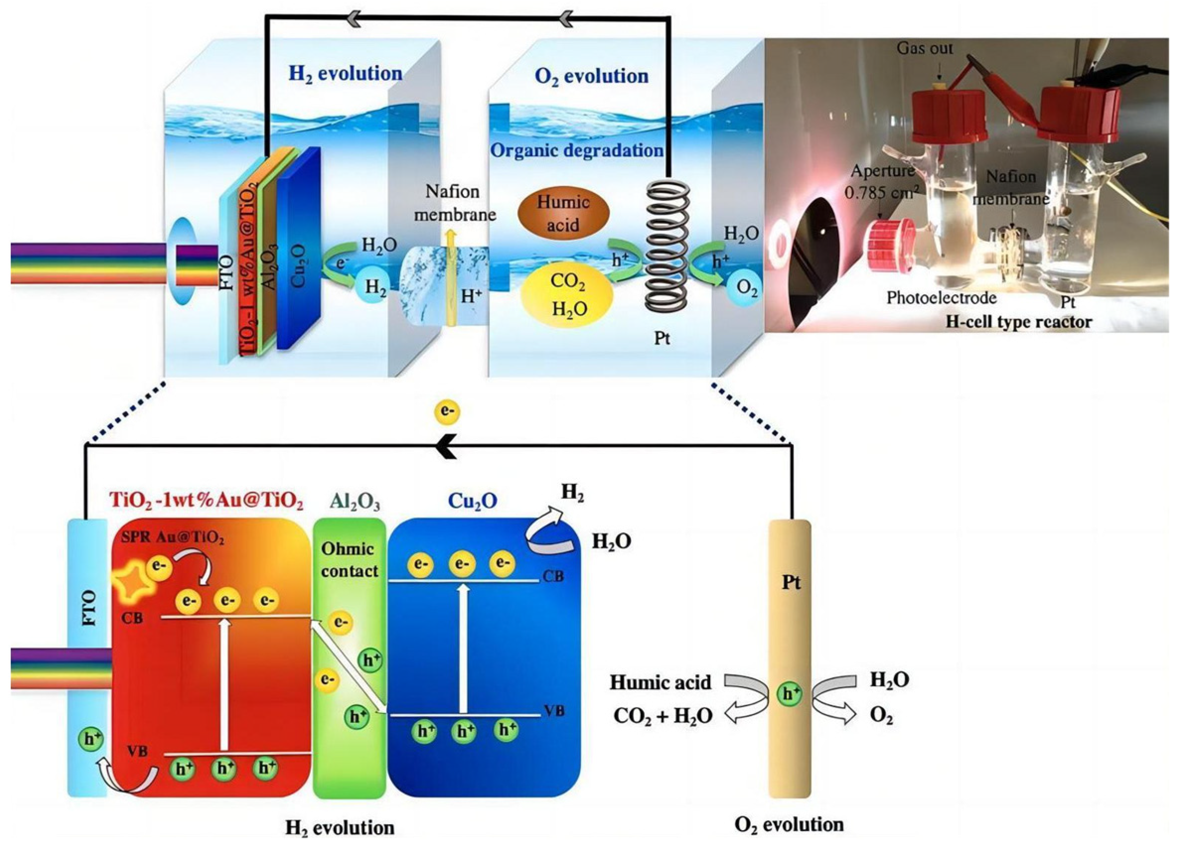
In addition to doping, the separation of photogenerated electron–hole pairs can be promoted by constructing BiVO4 heterojunctions to improve PEC performance. Liang et al. [58] reported on highly efficient and reproducible BiVO4 photoanodes prepared by a new spray pyrolysis method. As shown in Figure 10, the collection and transfer of carrier charge was substantially improved due to the blocking effect induced on holes, attributable to SnO2 being introduced as a thin interfacial layer between the FTO and BiVO4. The strategy of using a thin SnO2 layer as a hole mirror can benefit other photoanode materials to avoid the recombination of defect states at the FTO/BiVO4 interface. This provides an effective method for enhancing the hydrogen production efficiency of FTO-based photoelectrode materials.
Li et al. [59] synthesized a Bi2S3/BiVO4 photoelectrode with a heterojunction structure through a two-step conversion process. As shown in Figure 11a, it is obvious that the hybrid Bi2S3/BiVO4 nanostructure exhibited a higher photocurrent density than the bare BiVO4. Compared with Figure 4A, the photocurrent density curve has a sharp decrease at the beginning of each cycle. This phenomenon is caused by the recombination of partial photogenerated charges in the composite, which is very common in composites with heterojunction structures [42,43]. Meanwhile, the results showed that Bi2S3/BiVO4 has a higher carrier concentration relative to the bare BiVO4. In addition, the flat band potential had a negative shift for the hybrid Bi2S3/BiVO4 compared with the bare BiVO4, which was ascribed to the more negative position of the conduction band for Bi2S3 than that of BiVO4 (Figure 11b). The negative flat band potential shift contributed to the separation of the photogenerated charge. Because the energy band positions of Bi2S3 were both more negative than that of BiVO4, the photoelectrons in the conduction band of Bi2S3 transferred to the conduction band of BiVO4, and the photogenerated holes transferred from BiVO4 to Bi2S3 in the same way (Figure 12). The photocharge recombination can be effectively suppressed, which improves the photocurrent density.

3.1.3. Cu2O

Cu2O has attracted considerable interest in the field of PECs since Kondo et al. [60]. first reported that Cu2O can photocatalytically carry out complete water decomposition in 1998. Cu2O has a narrow band gap of about 2.1 eV and a high absorption coefficient. It shows red, orange, and other different colors due to its different synthesis methods and particle sizes. Cu2O has various advantages, such as its appropriate band gap, excellent photoelectric performance, simple preparation, and low cost. However, Cu2O photocathodes are extremely prone to photocorrosion due to their oxidation–reduction potentials located in the band gap of Cu2O [61,62]. At present, a large number of studies in the literature are devoted to the stability of Cu2O as a photocathode in the process of PECs. Siripala et al. [63] first proposed that the stability of a Cu2O photocathode can be substantially improved if a TiO2 protective layer with a thickness of about 100 nm is deposited on the surface of Cu2O by the electron beam method.
Wu et al. [64] reported a MoS2/Cu2O nanohybrid prepared by a simple wet chemical method. This heterojunction structure effectively promoted the separation of photogenerated electron–hole pairs, resulting in a significant increase in the photocurrent of the nanohybrid. Peerakiatkhajohn et al. [65] originally introduced a Al2O3 thin-film layer between Au@TiO2 and Cu2O. On the one hand, strong inherent electric fields at the interfaces, produced by the introduction of an extremely thin Al2O3 film, suppress the recombination of photogenerated electron–hole pairs. On the other hand, humic acid served as an electron donor to clear holes and suppressed electron hole recombination by capturing the remaining holes. In the presence of humic acid, the hydrogen production efficiency of the PEC device was significantly improved. A bifunctional PEC system with the function of simultaneous hydrogen production and humic degradation was achieved through using the multi-layer Au@TiO2/Al2O3/Cu2O photoelectrodes, as shown in Figure 13.

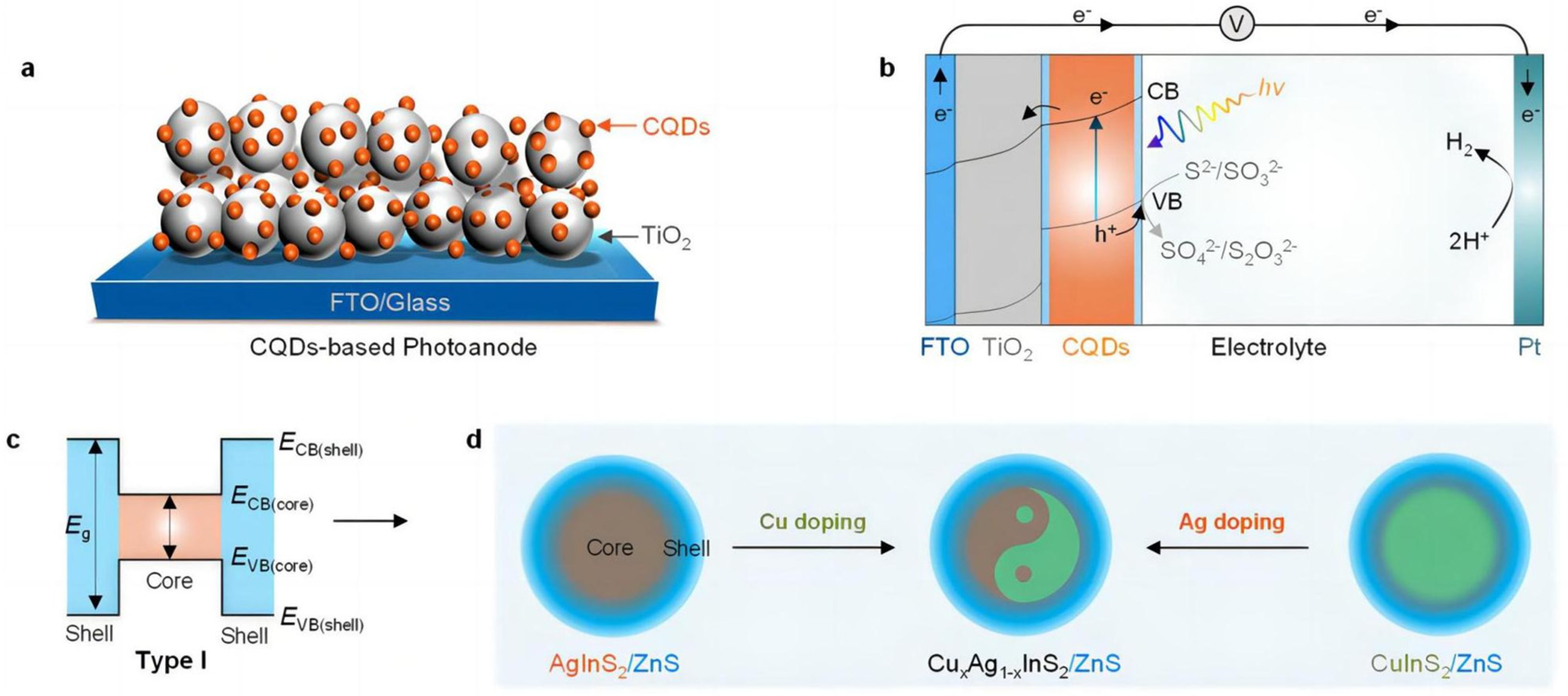
3.2. Sulfide Materials

Metal sulfides such as cadmium sulfide (CdS), cadmium zinc sulfide solid solution (ZnxCd1−xS), and indium zinc sulfide (ZnIn2S4) have been extensively studied for their wide range of sources, simple preparation methods, appropriate band structures, and good PEC activity. Solid-phase synthesis is one of the important methods for preparing sulfides. Bao et al. [66] prepared CdS nanocrystals via the pyrolysis of a cadmium thiourea complex at high temperature in a N2 atmosphere. However, the crystal produced by this method had a large crystalline grain size and small specific surface area, which is not conducive to the PEC reaction.
With the development of colloidal chemistry, people have gradually developed a variety of liquid-phase synthesis methods to prepare sulfide materials with high PEC performance. In early studies, CdS was often prepared by a chemical precipitation method, and the precursor was usually cadmium brine solution. H2S, Na2S, thiourea, and other sulfur-containing organic or inorganic compounds are used as precipitants [67]. The microwave hydrothermal method is also an important synthesis method for preparing high-quality sulfides. The electromagnetic field in the microwave reactor changes direction at a frequency of tens of thousands of hertz, causing the dipolar vibration of reactant molecules. The entire reaction system is heated rapidly and evenly, which greatly improves the reaction rate [68].

3.2.1. Doping

For sulfide semiconductors, doping is also an effective way to adjust their band structures for improving PEC performance. Tian et al. [69], Zhang et al. [70], and Barpuzary et al. [71], respectively, incorporated Cu, Co, and Mn elements into CdS, which introduces shallow energy levels into its band gap, improving the PEC performance of doped CdS due to the enhancement in carrier separation efficiency and visible light absorption. As shown in Figure 14, compared with the XPS spectrum of the CdS, the two peaks corresponding to Cd3d5/2 (404.1 eV) and Cd3d3/2 (411.7 eV) had a slight shift towards to a higher binding energy. The introduction of Cu2+ changed the crystal structure of CdS due to the introduction of lattice defects. Similarly, the absorption edge of the UV/Vis spectrum shifted to red because of the Cu defect states formed in the forbidden gap (Figure 15). The 7% Cu-CdS exhibited the best hydrogen production ability, with a rate of 1115 µmol h−1 g−1, which is almost 5.3 times higher than that of undoped CdS of 212 µmol h−1 g−1 (Figure 16A). Furthermore, a Cu-CdS/MoS2 composite can reach a hydrogen production rate of 10.18 mmol h−1 g−1, which is about 48 times higher than that of pure CdS (Figure 16B). MoS2 can provide a lot of active sites at the edge of its sheets, leading to improved hydrogen production. The photoelectric performances of photoelectrodes with composite structures are often better than those based on pure doping.
In addition to doping, the energy band structure of sulfides can also be modified by forming solid solutions with different precursors of sulfides. The energy band structure of solid solutions can be precisely controlled by changing the composition of different precursors. For example, the band gaps of ZnxCd1−xS [72] and CuxAg1−xInS2 [73] can be precisely tuned by adjusting the composition of Zn/Cd and Cu/Ag, respectively. In this case, both of the tuned sulfides can respond to visible light, allowing for the efficient utilization of solar energy. Moreover, such solid solutions show better PEC performances than doped sulfides.

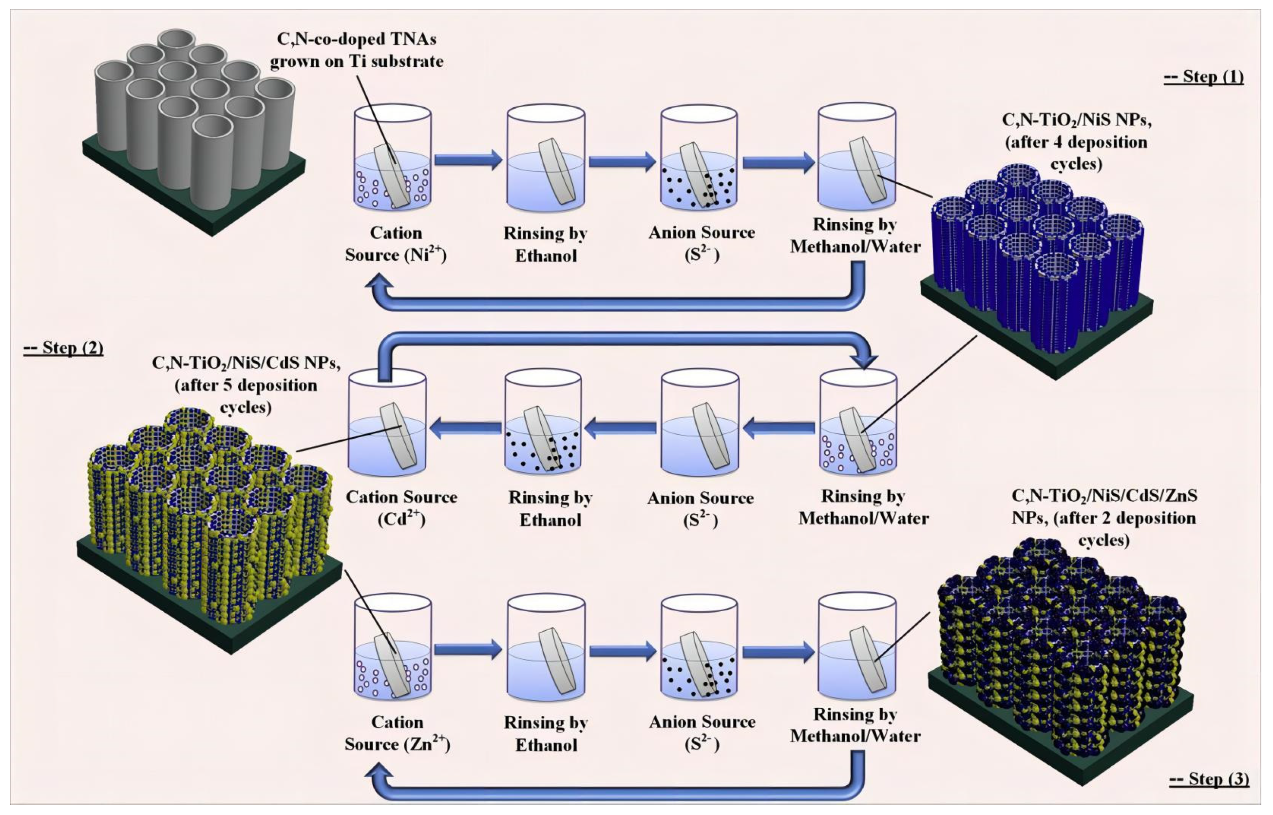
3.2.2. Sulfide-Based Composites

Like sulfides, sulfide-based composites have also attracted considerable attention [74]. Gao et al. [75] prepared ZnIn2S4 nanosheets on flexible graphite felt by using a hydrothermal method. They found that a photoelectrode with a 5 mm-thick graphite felt and ZnIn2S4 coating exhibited the best PEC properties compared to other photoelectrodes. Guo et al. [73] designed a series of CuxAg1−xInS2/ZnS colloidal quantum dots (CQDs) by the defect passivation of a ZnS shell and the incorporation of Cu ions to engineer its band structure. ZnS shell-assisted defect passivation suppressed charge carrier recombination because of the formation of the core/shell heterojunction interface, enhancing the performance of PEC devices with better charge separation and stability. Furthermore, Cu ion doping in AgInS2 CQDs results in a shift in the energy band of the quantum dots, which greatly promote the interface’s charge separation and transfer (Figure 17).
Mollavali [76] reported the composite structures of a variety of sulfides on Co-doped/modified TiO2. TiO2 nanostructures were first sensitized by nitrogen and carbon with a one-step low-cost anodic oxidation process, and then NiS/CdS/ZnS NPs were deposited on the surfaces of TiO2 nanostructures by successive ionic layer adsorption and using a successive ionic layer adsorption and reaction (SILAR) method at room temperature (Figure 18). These vertically aligned C, N-co-doped TiO2 nanotube arrays (TNAs) electrode provide a large surface area for the deposition of NPs, and they are also well-defined channels for efficient charge transport (Figure 19a). The NiS nanoparticles have small aggregation rather than large aggregation on the top of the TNAs (Figure 19b). Although some aggregates of the nanoparticles can be observed in the final photoanode due to the dense particle loading, the nanotubes remain predominantly open after all deposition steps, which is an important factor to maximize light absorbance and photoactivity, as well as electrolyte transport (Figure 19c,d). The optical properties of a C, N-TiO2/NiS/CdS/ZnS photoanode were enhanced due to a reduction in the recombination of electrons and holes, improving the surface carrier transfer rate and photogenerated carrier separation.

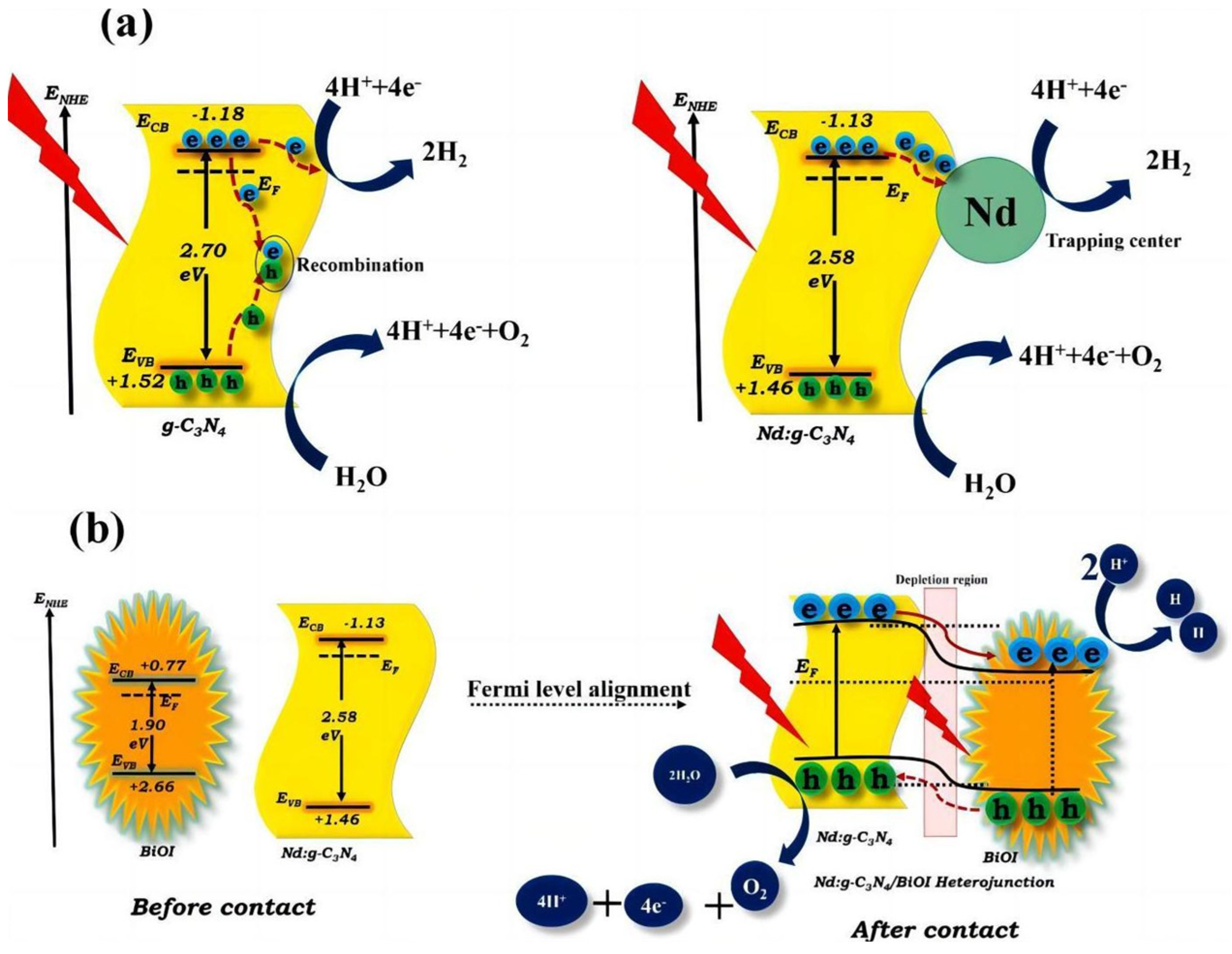
3.3. Graphite-Phase Carbon Nitride (g-C3N4)

In 2009, Wang [77] first reported that g-C3N4 can photocatalytically decompose water into hydrogen and oxygen with a sacrificial agent under visible light. The band gap of g-C3N4 is 2.7 eV. Its minimum conduction band and maximum valence band are −1.1 eV and +1.6 eV, respectively, which makes it possible to decompose water completely under visible light. It can be made by calcining common raw materials such as melamine, cyanuric chloride, and urea at high temperature. The C/N ratio of g-C3N4 varies depending on the calcination temperature [78].

3.3.1. Doping

Wang et al. [79] found that fluorine doping into g-C3N4 can form a C-F bond, narrowing its band gap and increasing its optical absorption range. Wu et al. [80] reported that phosphorus (P)-doped g-C3N4 synthesized by a simple sintering method exhibited 1.4 μA/cm2 of photocurrent at 1.2 V versus Ag/AgCl under near-IR light (>800 nm) irradiation. The introduction of P into g-C3N4 reduced its bandgap from 2.75 eV to 1.37 eV, in favor of a superior infrared light response. Meanwhile, the doping of P also improved the separation and transfer of photogenerated charges. In addition to non-metal doping, metal doping has also been extensively used to improve the PEC performance of g-C3N4. Rouby et al. [81] reported on the synthesis of an elongated g-C3N4 nanostructure which was fabricated by the direct pyrolysis of a supramolecular melamine precursor. The as-prepared material was used to host specific amounts of bismuth, a doping element used to adjust the band gap of the hosting matrix. XRD measurements confirmed the absence of bismuth oxide in the photoanode (Figure 20). The bandgap width was reduced due to the introduction of Bi in g-C3N4 (Figure 21). The 2.5% Bi-doped g-C3N4 photoelectrode was twice as efficient as pure g-C3N4 in terms of PEC water decomposition. The schematic diagram shown in Figure 22 shows the energy band structure of a typical element-doped and molecularly modified g-C3N4 sample.

3.3.2. g-C3N4 Composites

Semiconductor heterojunctions can effectively promote the separation of photogenerated electron–hole pairs, thus enhancing the PEC activity of semiconductor materials. As a kind of flexible material, g-C3N4 is beneficial for closely compounding with other semiconductors. Available materials include metal oxides (ZnO [83,84], TiO2 [85,86], WO3 [87], BiIO [88], Al2O3 [89]), sulfides (CdS [90], MoS2 [91]), graphene [92], activated carbon [93], and noble metal Au [94]. Velusamy et al. [88] prepared a noble metal-free nano-het-erostructure of neodymium (Nd)-doped graphitic carbon nitride (g-C3N4) and bismuth oxyiodide (BiOI) by using a two-step thermal poly-condensation and hydrothermal method. The doping of Nd reduced the bandgap width of the photoelectrode, thereby increasing its response range to visible light. At the same time, the construction of heterojunctions can improve the transfer and suppress the recombination of photogenerated charges. The combination of the two methods improves the optical and electrical properties of the photoelectrode, leading to an enhancement in PEC performance (Figure 23).

4. Strategies to Improve the Efficiency of PEC Hydrogen Evolution

Based on the present understanding of the principle of PECs, we discussed the promising semiconductor materials and related experimental methods and means currently used in the PEC decomposition of water. PEC hydrogen evolution involves diversiform chemical and physical processes such as the preparation of a photoelectrode material, photon absorption, semiconductor excitation, and the separation and migration of electron–hole pairs. Considering these important chemical and physical processes involved in PECs, this section summarizes strategies that might be useful for improving the efficiency of PEC hydrogen production.

4.1. Morphological Control

The morphological properties of semiconductor photoelectrode materials, such as the thickness of film electrodes and the surface microstructure, have a very important influence on PEC efficiency. For example, the morphology of single-crystalline TiO2 NTs is beneficial for directional charge transport due to their nanotube confinement effect [95]. In one study, after size-controllable g-C3N4 quantum dots (QDs) were synthesized in situ and grafted onto TiO2 NTs, the unique morphology and structure efficiently inhibited self-gathering and the leaching of g-C3N4 QDs, leading to excellent PEC performance [95]. The reactions of oxidation and reduction occur only when the carrier charges migrate from the inside to the surface of the semiconductor photoelectrode or counter electrode. Thus, a considerable part of the carrier charges is likely to recombine before they reach the electrode surface due to the low carrier mobility or excessive thickness of the photoelectrode film. In this case, the thinner the photoelectrode film is, the faster the carrier charges can be transferred to the surface of the photoelectrode. However, excessive reduction of the thickness of the photoelectrode film will weaken the light absorption [96,97]. Therefore, a balance regarding the light harvest and fast transfer of the carrier charges should be achieved by optimizing the thickness of the photoelectrode film [98].
It is well known that crystal surfaces play an important role in the PEC activity of photoelectrodes. Compared with a stable anatase (101) crystal surface, a metastable (001) crystal surface has more unsaturated coordination surface dangling bonds. Yang [99] was the first to successfully synthesize anatase TiO2 micro crystals with an exposure ratio of (001) crystal plane up to 47% through the regulation of hydrofluoric acid (HF). This groundbreaking work led to an upsurge in the study of anatase (001) facet synthesis and related PEC properties. However, HF is highly corrosive. Thus, various fluorides have been used as additives to study the effect of stabilizing (001) crystal facets, including ammonium fluoride, ammonium hydrogen fluoride, sodium fluoride, or fluorine-containing surfactants [100]. BiVO4 film photoelectrodes composed of nanoplates with highly reactive exposed facets (001) also exhibit a photocurrent density more than five times higher than that of nanorods grown along the (100) direction. Similarly, WO3 nanomultilayers with highly exposed (002) facets (60%) exhibited much better PEC performances than WO3 nanorods with less exposed (002) facets (20%) [31].

4.2. Doping

Doping can create defect energy levels in the bandgap of a semiconductor, thus changing its energy band structure. On one hand, the defect energy levels usually offer a narrow sub-bandgap in the semiconductor, contributing to increasing the light absorption; on the other hand, the defect energy levels can form a charge capture center and thus increase the carrier life. In addition, doping can also regulate the electrical properties of semiconductors, such as carrier concentration and carrier mobility, enhance the conductivity and carrier mobility of semiconductors, and improve the efficiency of charge separation and transfer [101,102,103]. Therefore an optimal amount of doping should be determined for photoelectrode materials to achieve optimal PEC performance [104].

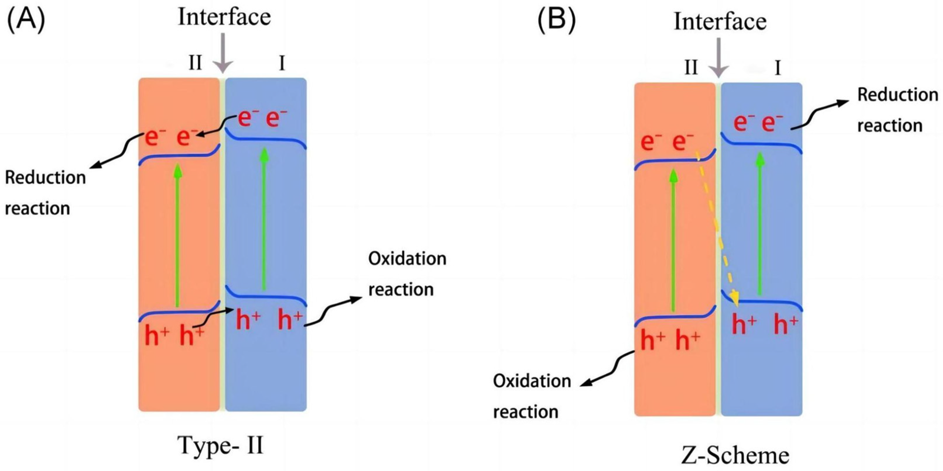
4.3. Heterojunctions

A heterojunction is the interfacial contact region of two different semiconductors; heterojunctions are mainly divided into types Ⅰ, Ⅱ, and Ⅲ. As shown in Figure 24a, in a type-Ⅰ heterojunction, both the conduction band (CB) and the valence band (VB) of semiconductor A are included in the bandgap of semiconductor B. The photogenerated electrons transfer from CB(B) to CB(A), while the photogenerated holes transfer from VB(B) to VB(A). All photogenerated charges are accumulated in semiconductor A, probably resulting in the recombination problem of charge carriers. In a type-Ⅱ heterojunction (Figure 24b), both the CB and the VB of semiconductor B are more negative than those of semiconductor A, meanwhile, the VB of semiconductor B is located in the bandgap of semiconductor A. In this case, the photogenerated electrons and holes are likely to accumulate in the CB (A) and VB(B), respectively, improving the efficiency of the separation of carrier charges, thus enhancing the PEC decomposition of water. Numerous composite photoelectrodes mentioned above employ this type-Ⅱ heterojunction structure. For example, the PEC performance of TiO2 can be significantly improved when coupled with Cu2O [105] and ZnO [106] to form type-Ⅱ heterojunctions. In a type-Ⅲ heterojunction (Figure 24c), the whole band position of semiconductor B is further offset to that of semiconductor A. Such arrangements of band positions are also called broken-gap situations.
For type-II heterojunctions, despite the fact that they can effectively separate the charge, their oxidation–reduction abilities have not yet been maximized in this system. In contrast, Z-scheme heterojunctions can achieve strong oxidation–reduction abilities. As shown in Figure 25 [108], in Z-scheme heterojunctions, the photogenerated electrons in semiconductor II are inclined to combine with the photogenerated holes in semiconductor I. In this case, the photogenerated electrons and holes are likely to accumulate in the CB of semiconductor I and VB of semiconductor II, respectively. The structures of Z-scheme heterojunctions can both enhance the separation of charge carriers and retain the strong reduction and oxidation ability, thus improving the PEC performance of the photoelectrode.

4.4. Surface Modification

Metals, especially noble metals (such as Pt) with large work functions (i.e., low Fermi levels) can effectively collect electrons and enjoy a low activation energy and overpotential for the hydrogen production reaction. Therefore, noble metals are often considered as suitable cocatalysts for PEC hydrogen production. Pop et al. [109] reported a “PEC Leaf” photoelectrode consisting of nano titanium dioxide particles as photocatalysts and a commercial carbon paste enriched with a small quantity of Pt NPs (0.0134 mg/cm2) as electrocatalysts. As shown in Figure 26, Pt can effectively enrich photogenerated electrons from the photoelectrode, greatly improving hydrogen production efficiency with the help of a sacrificial agent. It is worth noting that the loading amount of Pt directly affects the PEC performance of the sample, and the excessive loading of Pt will lead to a decrease in the PEC performance of the sample [110]. In addition, the hydrogen production performance of photoelectrodes can also be affected by the particle size and shape of the noble metal cocatalyst [111].
However, the high cost of noble metals limits their use on a large scale. So, some transition metals and oxides have been used as low-cost substitutes, such as NiO [112] and CuO [113]. Kim et al. [114] reported a ternary hybrid solar desalination process coupled with PEC water treatment and H2 production in a low-cost device with an oxide photoelectrode and transition sulfate cathode. The desalination of brackish water in the desalination cell is initiated via photoinduced charge generation with a thermochemically reduced TiO2 nanorod array photoanode. As shown in Figure 27, a three-cell device was designed to achieve hydrogen production and seawater desalination. The Ni-Mo-S composite catalyst greatly promoted the generation of hydrogen at the cathode, thereby improving the seawater desalination rate of the entire device.

5. Concluding Remarks

An overview of promising semiconductor materials for efficient PEC hydrogen production has been given. The general characteristics, preparation methods, and applications of metal oxides, sulfide materials, and g-C3N4, as well as their modifications and composites, have been covered, as summarized in Table 1. The benefits and drawbacks of the photoelectrode materials and their corresponding remedial schemes have also been discussed. An efficient PEC photoelectrode should possess an appropriate energy band structure, wide wavelength light absorption, effective carrier separation and transport, and high stability. Doping and modification are effective approaches for improving the PEC performance of hydrogen evolution and stability of photoelectrode materials. Particularly, constructing type-II and Z-scheme heterojunctions using multiple materials is also a good way to effectively promote the separation and transport of carrier charges. We hope a comprehensive understanding of the relationship between the structures and properties of semiconductor materials will benefit the precise control of semiconductor materials as photoelectrodes and thus promote the development of PEC hydrogen production.

Author Contributions

Conceptualization, L.X. and H.Y.; original draft preparation, W.F., Y.Z. and X.Z.; writing, W.F.; writing—review and editing, R.X., S.Z. and Y.L.; supervision and funding acquisition, L.X. and H.Y. All authors have read and agreed to the published version of the manuscript.

Funding

The authors acknowledge the support of the Natural Science Foundation of Guangdong Province (2021A1515012594), Guangdong Province Office of Education (2020ZDZX2028, 2021gszlgc01), United Laboratory of College and Enterprise (GSZLGC2023005), Science and Technology Projects of Guangzhou (202201011335, 202201011256), Guangdong Basic and Applied Basic Research Foundation (2022A1515110463, 2021A1515110803), Jiangxi Provincial Natural Science Foundation (GJJ2201422), and the Scientific Research Foundation of Gannan Medical University (QD202115, XN202004).

Institutional Review Board Statement

Not applicable.

Informed Consent Statement

Not applicable.

Data Availability Statement

Not applicable.

Conflicts of Interest

The authors declare no conflicts of interest.

References

  1. Abe, J.O.; Popoola, A.; Ajenifuja, E.; Popoola, O.M. Hydrogen energy, economy and storage: Review and recommendation. Int. J. Hydrogen Energy 2019, 44, 15072–15086. [Google Scholar] [CrossRef]
  2. Mao, Z. Hydrogen Energy: Green Energy in 21st Century; Chemical Industry Press: Beijing, China, 2005; ISBN 9787502560393. [Google Scholar]
  3. Dragomir, G.; Șerban, A.; Năstase, G.; Brezeanu, A.I. Wind energy in Romania: A review from 2009 to 2016. Renew. Sustain. Energy Rev. 2016, 64, 129–143. [Google Scholar] [CrossRef]
  4. Menyah, K.; Wolde-Rufael, Y. CO2 emissions, nuclear energy, renewable energy and economic growth in the US. Energy Policy 2010, 38, 2911–2915. [Google Scholar] [CrossRef]
  5. Qi, J.; Zhang, W.; Cao, R. Solar-to-hydrogen energy conversion based on water splitting. Adv. Energy Mater. 2018, 8, 1701620. [Google Scholar] [CrossRef]
  6. Shaner, M.R.; Atwater, H.A.; Lewis, N.S.; McFarland, E.W. A comparative technoeconomic analysis of renewable hydrogen production using solar energy. Energy Environ. Sci. 2016, 9, 2354–2371. [Google Scholar] [CrossRef]
  7. Hisatomi, T.; Kubota, J.; Domen, K. Recent advances in semiconductors for photocatalytic and photoelectrochemical water splitting. Chem. Soc. Rev. 2014, 43, 7520–7535. [Google Scholar] [CrossRef] [PubMed]
  8. Haussener, S.; Xiang, C.; Spurgeon, J.M.; Ardo, S.; Lewis, N.S.; Weber, A.Z. Modeling, simulation, and design criteria for photoelectrochemical water-splitting systems. Energy Environ. Sci. 2012, 5, 9922–9935. [Google Scholar] [CrossRef]
  9. Fujishima, A.; Honda, K. Electrochemical photolysis of water at a semiconductor electrode. Nature 1972, 238, 37–38. [Google Scholar] [CrossRef]
  10. Trasatti, S. Work function, electronegativity, and electrochemical behaviour of metals: III. Electrolytic hydrogen evolution in acid solutions. J. Electroanal. Chem. Interfacial Electrochem. 1972, 39, 163–184. [Google Scholar] [CrossRef]
  11. Li, X.; Yu, J.; Low, J.; Fang, Y.; Xiao, J.; Chen, X. Engineering heterogeneous semiconductors for solar water splitting. J. Mater. Chem. A 2015, 3, 2485–2534. [Google Scholar] [CrossRef]
  12. Serpone, N.; Emeline, A.V.; Ryabchuk, V.K.; Kuznetsov, V.N.; Artem’ev, Y.M.; Horikoshi, S. Why do hydrogen and oxygen yields from semiconductor-based photocatalyzed water splitting remain disappointingly low? Intrinsic and extrinsic factors impacting surface redox reactions. ACS Energy Lett. 2016, 1, 931–948. [Google Scholar] [CrossRef]
  13. Kenney, M.J.; Gong, M.; Li, Y.; Wu, J.Z.; Feng, J.; Lanza, M.; Dai, H. High-performance silicon photoanodes passivated with ultrathin nickel films for water oxidation. Science 2013, 342, 836–840. [Google Scholar] [CrossRef] [PubMed]
  14. Ma, Q.-B.; Kaiser, B.; Jaegermann, W. Novel photoelectrochemical behaviors of p-SiC films on Si for solar water splitting. J. Power Source 2014, 253, 41–47. [Google Scholar] [CrossRef]
  15. Walter, M.G.; Warren, E.L.; McKone, J.R.; Boettcher, S.W.; Mi, Q.; Santori, E.A.; Lewis, N.S. Solar water splitting cells. Chem. Rev. 2010, 110, 6446–6473. [Google Scholar] [CrossRef] [PubMed]
  16. Yang, W.; Prabhakar, R.R.; Tan, J.; Tilley, S.D.; Moon, J. Strategies for enhancing the photocurrent, photovoltage, and stability of photoelectrodes for photoelectrochemical water splitting. Chem. Soc. Rev. 2019, 48, 4979–5015. [Google Scholar] [CrossRef] [PubMed]
  17. Bahnemann, D.W.; Hilgendorff, M.; Memming, R. Charge carrier dynamics at TiO2 particles: Reactivity of free and trapped holes. J. Phys. Chem. B 1997, 101, 4265–4275. [Google Scholar] [CrossRef]
  18. Pham, T.A.; Ping, Y.; Galli, G. Modelling heterogeneous interfaces for solar water splitting. Nat. Mater. 2017, 16, 401–408. [Google Scholar] [CrossRef]
  19. Shi, X.; Jeong, H.; Oh, S.J.; Ma, M.; Zhang, K.; Kwon, J.; Choi, I.T.; Choi, I.Y.; Kim, H.K.; Kim, J.K. Unassisted photoelectrochemical water splitting exceeding 7% solar-to-hydrogen conversion efficiency using photon recycling. Nat. Commun. 2016, 7, 11943. [Google Scholar] [CrossRef]
  20. Grätzel, M. Photoelectrochemical cells. Nature 2001, 414, 338–344. [Google Scholar] [CrossRef]
  21. Li, T.; He, J.; Peña, B.; Berlinguette, C.P. Curing BiVO4 photoanodes with ultraviolet light enhances photoelectrocatalysis. Angew. Chem. Int. Ed. 2016, 55, 1769–1772. [Google Scholar] [CrossRef]
  22. Monfort, O.; Pop, L.-C.; Sfaelou, S.; Plecenik, T.; Roch, T.; Dracopoulos, V.; Stathatos, E.; Plesch, G.; Lianos, P. Photoelectrocatalytic hydrogen production by water splitting using BiVO4 photoanodes. Chem. Eng. J. 2016, 286, 91–97. [Google Scholar] [CrossRef]
  23. Gu, Y.-E.; Zhang, Y.; Zhang, F.; Wei, J.; Wang, C.; Du, Y.; Ye, W. Investigation of photoelectrocatalytic activity of Cu2O nanoparticles for p-nitrophenol using rotating ring-disk electrode and application for electrocatalytic determination. Electrochim. Acta 2010, 56, 953–958. [Google Scholar] [CrossRef]
  24. e Silva, B.C.; Irikura, K.; Flor, J.B.S.; Dos Santos, R.M.M.; Lachgar, A.; Frem, R.C.G.; Zanoni, M.V.B. Electrochemical preparation of Cu/Cu2O-Cu (BDC) metal-organic framework electrodes for photoelectrocatalytic reduction of CO2. J. CO2 Util. 2020, 42, 101299. [Google Scholar] [CrossRef]
  25. Farooq, U.; Chaudhary, P.; Ingole, P.P.; Kalam, A.; Ahmad, T. Development of cuboidal KNbO3@ α-Fe2O3 hybrid nanostructures for improved photocatalytic and photoelectrocatalytic applications. ACS Omega 2020, 5, 20491–20505. [Google Scholar] [CrossRef] [PubMed]
  26. Cheng, L.; Tian, Y.; Zhang, J. Construction of pn heterojunction film of Cu2O/α-Fe2O3 for efficiently photoelectrocatalytic degradation of oxytetracycline. J. Colloid Interface Sci. 2018, 526, 470–479. [Google Scholar] [CrossRef] [PubMed]
  27. Fernández-Domene, R.M.; Sánchez-Tovar, R.; Lucas-Granados, B.; Muñoz-Portero, M.-J.; Garcia-Anton, J. Elimination of pesticide atrazine by photoelectrocatalysis using a photoanode based on WO3 nanosheets. Chem. Eng. J. 2018, 350, 1114–1124. [Google Scholar] [CrossRef]
  28. Mohite, S.; Ganbavle, V.; Rajpure, K. Photoelectrocatalytic activity of immobilized Yb doped WO3 photocatalyst for degradation of methyl orange dye. J. Energy Chem. 2017, 26, 440–447. [Google Scholar] [CrossRef]
  29. Rabell, G.O.; Cruz, M.A.; Juárez-Ramírez, I. Hydrogen production of ZnO and ZnO/Ag films by photocatalysis and photoelectrocatalysis. Mater. Sci. Semicond. Process. 2021, 134, 105985. [Google Scholar] [CrossRef]
  30. Sapkal, R.; Shinde, S.; Mahadik, M.; Mohite, V.; Waghmode, T.; Govindwar, S.; Rajpure, K.; Bhosale, C. Photoelectrocatalytic decolorization and degradation of textile effluent using ZnO thin films. J. Photochem. Photobiol. B 2012, 114, 102–107. [Google Scholar] [CrossRef]
  31. Wang, S.; Liu, G.; Wang, L. Crystal facet engineering of photoelectrodes for photoelectrochemical water splitting. Chem. Rev. 2019, 119, 5192–5247. [Google Scholar] [CrossRef]
  32. Yang, W.; Moon, J. Recent advances in earth-abundant photocathodes for photoelectrochemical water splitting. ChemSusChem 2019, 12, 1889–1899. [Google Scholar] [CrossRef] [PubMed]
  33. Kim, J.H.; Lee, J.S. Elaborately modified BiVO4 photoanodes for solar water splitting. Adv. Mater. 2019, 31, 1806938. [Google Scholar] [CrossRef] [PubMed]
  34. Gu, Z.; An, X.; Liu, R.; Xiong, L.; Tang, J.; Hu, C.; Liu, H.; Qu, J. Interface-modulated nanojunction and microfluidic platform for photoelectrocatalytic chemicals upgrading. Appl. Catal. B 2021, 282, 119541. [Google Scholar] [CrossRef]
  35. Ray, C.; Pal, T. Retracted Article: Recent advances of metal–metal oxide nanocomposites and their tailored nanostructures in numerous catalytic applications. J. Mater. Chem. A 2017, 5, 9465–9487. [Google Scholar] [CrossRef]
  36. Gong, J.; Pu, W.; Yang, C.; Zhang, J. Novel one-step preparation of tungsten loaded TiO2 nanotube arrays with enhanced photoelectrocatalytic activity for pollutant degradation and hydrogen production. Catal. Commun. 2013, 36, 89–93. [Google Scholar] [CrossRef]
  37. Sun, Y.; Wang, G.; Yan, K. TiO2 nanotubes for hydrogen generation by photocatalytic water splitting in a two-compartment photoelectrochemical cell. Int. J. Hydrogen Energy 2011, 36, 15502–15508. [Google Scholar] [CrossRef]
  38. Liu, Y.; Wang, P.; Wang, C.; Ao, Y. Polymeric carbon nitride coated Nb-TiO2 nanorod arrays with enhanced photoelectrocatalytic activity under visible light irradiation. Inorg. Chem. Commun. 2019, 101, 113–116. [Google Scholar] [CrossRef]
  39. See, A.; Bartynski, R. Inverse photoemission study of the defective TiO2 (110) surface. J. Vac. Sci. Technol. A Vac. Surf. Film. 1992, 10, 2591–2596. [Google Scholar] [CrossRef]
  40. Thomas, A.; Flavell, W.; Mallick, A.; Kumarasinghe, A.; Tsoutsou, D.; Khan, N.; Chatwin, C.; Rayner, S.; Smith, G.; Stockbauer, R. Comparison of the electronic structure of anatase and rutile TiO2 single-crystal surfaces using resonant photoemission and X-ray absorption spectroscopy. Phys. Rev. B 2007, 75, 035105. [Google Scholar] [CrossRef]
  41. Khan, M.A.; Woo, S.I.; Yang, O.-B. Hydrothermally stabilized Fe (III) doped titania active under visible light for water splitting reaction. Int. J. Hydrogen Energy 2008, 33, 5345–5351. [Google Scholar] [CrossRef]
  42. Liu, Z.; Song, Y.; Wang, Q.; Jia, Y.; Tan, X.; Du, X.; Gao, S. Solvothermal fabrication and construction of highly photoelectrocatalytic TiO2 NTs/Bi2MoO6 heterojunction based on titanium mesh. J. Colloid Interface Sci. 2019, 556, 92–101. [Google Scholar] [CrossRef] [PubMed]
  43. Adamopoulos, P.M.; Papagiannis, I.; Raptis, D.; Lianos, P. Photoelectrocatalytic hydrogen production using a TiO2/WO3 bilayer photocatalyst in the presence of ethanol as a fuel. Catalysts 2019, 9, 976. [Google Scholar] [CrossRef]
  44. Tatsuma, T.; Saitoh, S.; Ngaotrakanwiwat, P.; Ohko, Y.; Fujishima, A. Energy storage of TiO2-WO3 photocatalysis systems in the gas phase. Langmuir 2002, 18, 7777–7779. [Google Scholar] [CrossRef]
  45. Ngaotrakanwiwat, P.; Tatsuma, T. Optimization of energy storage TiO2-WO3 photocatalysts and further modification with phosphotungstic acid. J. Electroanal. Chem. 2004, 573, 263–269. [Google Scholar] [CrossRef]
  46. Takahashi, Y.; Ngaotrakanwiwat, P.; Tatsuma, T. Energy storage TiO2-MoO3 photocatalysts. Electrochim. Acta 2004, 49, 2025–2029. [Google Scholar] [CrossRef]
  47. Takahashi, Y.; Tatsuma, T. Oxidative energy storage ability of a TiO2-Ni(OH)2 bilayer photocatalyst. Langmuir 2005, 21, 12357–12361. [Google Scholar] [CrossRef] [PubMed]
  48. Yasomanee, J.; Bandara, J. Multi-electron storage of photoenergy using Cu2O–TiO2 thin film photocatalyst. Sol. Energy Mater. Sol. Cells 2008, 92, 348–352. [Google Scholar] [CrossRef]
  49. Xiong, L.; Ouyang, M.; Yan, L.; Li, J.; Qiu, M.; Yu, Y. Visible-light energy storage by Ti3+ in TiO2/Cu2O bilayer film. Chem. Lett. 2009, 38, 1154–1155. [Google Scholar] [CrossRef]
  50. Xiong, L.; Yang, F.; Yan, L.; Yan, N.; Yang, X.; Qiu, M.; Yu, Y. Bifunctional photocatalysis of TiO2/Cu2O composite under visible light: Ti3+ in organic pollutant degradation and water splitting. J. Phys. Chem. Solids 2011, 72, 1104–1109. [Google Scholar] [CrossRef]
  51. Kudo, A.; Omori, K.; Kato, H. A novel aqueous process for preparation of crystal form-controlled and highly crystalline BiVO4 powder from layered vanadates at room temperature and its photocatalytic and photophysical properties. J. Am. Chem. Soc. 1999, 121, 11459–11467. [Google Scholar] [CrossRef]
  52. Sayama, K.; Nomura, A.; Zou, Z.; Abe, R.; Abe, Y.; Arakawa, H. Photoelectrochemical decomposition of water on nanocrystalline BiVO4 film electrodes under visible light. Chem. Commun. 2003, 2908–2909. [Google Scholar] [CrossRef] [PubMed]
  53. Park, Y.; McDonald, K.J.; Choi, K.-S. Progress in bismuth vanadate photoanodes for use in solar water oxidation. Chem. Soc. Rev. 2013, 42, 2321–2337. [Google Scholar] [CrossRef] [PubMed]
  54. Faraji, M.; Yousefi, M.; Yousefzadeh, S.; Zirak, M.; Naseri, N.; Jeon, T.H.; Choi, W.; Moshfegh, A.Z. Two-dimensional materials in semiconductor photoelectrocatalytic systems for water splitting. Energy Environ. Sci. 2019, 12, 59–95. [Google Scholar] [CrossRef]
  55. Luo, W.; Wang, J.; Zhao, X.; Zhao, Z.; Li, Z.; Zou, Z. Formation energy and photoelectrochemical properties of BiVO4 after doping at Bi3+ or V5+ sites with higher valence metal ions. PCCP 2013, 15, 1006–1013. [Google Scholar] [CrossRef] [PubMed]
  56. Abdi, F.F.; Han, L.; Smets, A.H.; Zeman, M.; Dam, B.; Van De Krol, R. Efficient solar water splitting by enhanced charge separation in a bismuth vanadate-silicon tandem photoelectrode. Nat. Commun. 2013, 4, 2195. [Google Scholar] [CrossRef]
  57. Kim, T.W.; Ping, Y.; Galli, G.A.; Choi, K.-S. Simultaneous enhancements in photon absorption and charge transport of bismuth vanadate photoanodes for solar water splitting. Nat. Commun. 2015, 6, 8769. [Google Scholar] [CrossRef]
  58. Liang, Y.; Tsubota, T.; Mooij, L.P.; van de Krol, R. Highly improved quantum efficiencies for thin film BiVO4 photoanodes. J. Phys. Chem. C 2011, 115, 17594–17598. [Google Scholar] [CrossRef]
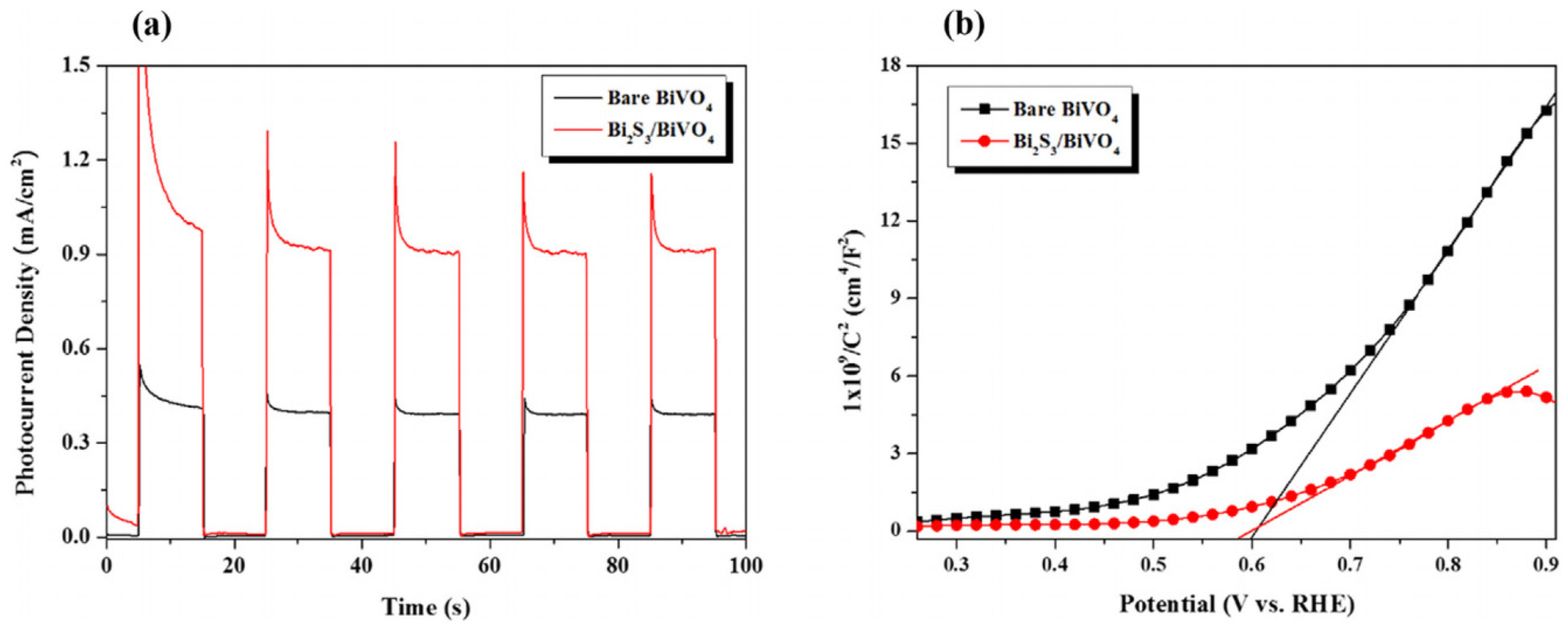
  59. Li, F.; Leung, D.Y. Highly enhanced performance of heterojunction Bi2S3/BiVO4 photoanode for photoelectrocatalytic hydrogen production under solar light irradiation. Chem. Eng. Sci. 2020, 211, 115266. [Google Scholar] [CrossRef]
  60. Kondo, J.N. Cu2O as a photocatalyst for overall water splitting under visible light irradiation. Chem. Commun. 1998, 357–358. [Google Scholar] [CrossRef]
  61. Xiong, L.; Yu, H.; Ba, X.; Zhang, W.; Yu, Y. Cu2O-Based Nanocomposites for Environmental Protection: Relationship between Structure and Photocatalytic Activity, Application, and Mechanism. In Nanomaterials for Environmental Protection; Kharisov, B.I., Kharissova, O.V., Dias, H.V.R., Eds.; John Wiley & Sons: Hoboken, NJ, USA, 2014; pp. 41–70. ISBN 9781118496978. [Google Scholar]
  62. Li, C.; He, J.; Xiao, Y.; Li, Y.; Delaunay, J.-J. Earth-abundant Cu-based metal oxide photocathodes for photoelectrochemical water splitting. Energy Environ. Sci. 2020, 13, 3269–3306. [Google Scholar] [CrossRef]
  63. Siripala, W.; Ivanovskaya, A.; Jaramillo, T.F.; Baeck, S.-H.; McFarland, E.W. A Cu2O/TiO2 heterojunction thin film cathode for photoelectrocatalysis. Sol. Energy Mater. Sol. Cells 2003, 77, 229–237. [Google Scholar] [CrossRef]
  64. Wu, Z.; Fei, H.; Wang, D. MoS2/Cu2O nanohybrid as a highly efficient catalyst for the photoelectrocatalytic hydrogen generation. Mater. Lett. 2019, 256, 126622. [Google Scholar] [CrossRef]
  65. Peerakiatkhajohn, P.; Yun, J.-H.; Butburee, T.; Chen, H.; Thaweesak, S.; Lyu, M.; Wang, S.; Wang, L. Bifunctional photoelectrochemical process for humic acid degradation and hydrogen production using multi-layered p-type Cu2O photoelectrodes with plasmonic Au@TiO2. J. Hazard. Mater. 2021, 402, 123533. [Google Scholar] [CrossRef] [PubMed]
  66. Bao, N.; Shen, L.; Takata, T.; Domen, K.; Gupta, A.; Yanagisawa, K.; Grimes, C.A. Facile Cd-thiourea complex thermolysis synthesis of phase-controlled CdS nanocrystals for photocatalytic hydrogen production under visible light. J. Phys. Chem. C 2007, 111, 17527–17534. [Google Scholar] [CrossRef]
  67. Tsuji, I.; Kato, H.; Kudo, A. Visible-Light-Induced H2 Evolution from an Aqueous Solution Containing Sulfide and Sulfite over a ZnS–CuInS2–AgInS2 Solid-Solution Photocatalyst. Angew. Chem. Int. Ed. 2005, 117, 3631–3634. [Google Scholar] [CrossRef]
  68. Cui, W.; Liu, Y.; Liu, L.; Hu, J.; Liang, Y. Microwave-assisted synthesis of CdS intercalated K4Nb6O17 and its photocatalytic activity for hydrogen production. Appl. Catal. A 2012, 417, 111–118. [Google Scholar] [CrossRef]
  69. Tian, H.; Liang, J.; Ma, X.; Cao, L.; Hu, X.; Gao, M.; Yang, H.; Liang, Z. Enhanced Photoelectrocatalytic H2 Evolution over Two-Dimensional MoS2 Nanosheets Loaded on Cu-Doped CdS Nanorods. ChemElectroChem 2019, 6, 714–723. [Google Scholar] [CrossRef]
  70. Zhang, T.; Zhang, H.; Ji, Y.; Chi, N.; Cong, Y. Preparation of a novel Fe2O3-MoS2-CdS ternary composite film and its photoelectrocatalytic performance. Electrochim. Acta 2018, 285, 230–240. [Google Scholar] [CrossRef]
  71. Barpuzary, D.; Khan, Z.; Vinothkumar, N.; De, M.; Qureshi, M. Hierarchically grown urchinlike CdS@ZnO and CdS@Al2O3 heteroarrays for efficient visible-light-driven photocatalytic hydrogen generation. J. Phys. Chem. C 2012, 116, 150–156. [Google Scholar] [CrossRef]
  72. Wang, J.; Li, J.; Xiao, L.; Kurbanjan, D.; Nie, H.; Du, H. Cation exchange synthesis of porous Cd1−xZnxS twinned nanosheets for visible light highly active H2 evolution. J. Am. Ceram. Soc. 2022, 105, 1405–1416. [Google Scholar] [CrossRef]
  73. Guo, H.; Yang, P.; Hu, J.; Jiang, A.; Chen, H.; Niu, X.; Zhou, Y. Band Structure Engineering and Defect Passivation of CuxAg1-xInS2/ZnS Quantum Dots to Enhance Photoelectrochemical Hydrogen Evolution. ACS Omega 2022, 7, 9642–9651. [Google Scholar] [CrossRef] [PubMed]
  74. Li, Q.; Cui, C.; Meng, H.; Yu, J. Visible-Light Photocatalytic Hydrogen Production Activity of ZnIn2S4 Microspheres Using Carbon Quantum Dots and Platinum as Dual Co-catalysts. Chem. Asian J. 2014, 9, 1766–1770. [Google Scholar] [CrossRef] [PubMed]
  75. Gao, B.; Chen, W.; Liu, J.; An, J.; Wang, L.; Sillanpãã, M. The photoelectrocatalytic performance of ZnIn2S4 nanosheets and microspheres grown on flexible graphite felt. J. Electroanal. Chem. 2019, 845, 144–153. [Google Scholar] [CrossRef]
  76. Mollavali, M.; Falamaki, C.; Rohani, S. Efficient light harvesting by NiS/CdS/ZnS NPs incorporated in C, N-co-doped-TiO2 nanotube arrays as visible-light sensitive multilayer photoanode for solar applications. Int. J. Hydrogen Energy 2018, 43, 9259–9278. [Google Scholar] [CrossRef]
  77. Wang, X.; Maeda, K.; Thomas, A.; Takanabe, K.; Xin, G.; Carlsson, J.M.; Domen, K.; Antonietti, M. A metal-free polymeric photocatalyst for hydrogen production from water under visible light. Nat. Mater. 2009, 8, 76–80. [Google Scholar] [CrossRef] [PubMed]
  78. Yan, S.; Li, Z.; Zou, Z. Photodegradation performance of g-C3N4 fabricated by directly heating melamine. Langmuir 2009, 25, 10397–10401. [Google Scholar] [CrossRef] [PubMed]
  79. Wang, Y.; Di, Y.; Antonietti, M.; Li, H.; Chen, X.; Wang, X. Excellent visible-light photocatalysis of fluorinated polymeric carbon nitride solids. Chem. Mater. 2010, 22, 5119–5121. [Google Scholar] [CrossRef]
  80. Wu, F.; Ma, Y.; Hu, Y.H. Near infrared light-driven photoelectrocatalytic water splitting over P-doped g-C3N4. ACS Appl. Energy Mater. 2020, 3, 11223–11230. [Google Scholar] [CrossRef]
  81. El Rouby, W.M.; Aboubakr, A.E.A.; Khan, M.D.; Farghali, A.A.; Millet, P.; Revaprasadu, N. Synthesis and characterization of Bi-doped g-C3N4 for photoelectrochemical water oxidation. Sol. Energy 2020, 211, 478–487. [Google Scholar] [CrossRef]
  82. Cao, S.; Low, J.; Yu, J.; Jaroniec, M. Polymeric photocatalysts based on graphitic carbon nitride. Adv. Mater. 2015, 27, 2150–2176. [Google Scholar] [CrossRef]
  83. Kuang, P.-Y.; Su, Y.-Z.; Chen, G.-F.; Luo, Z.; Xing, S.-Y.; Li, N.; Liu, Z.-Q. g-C3N4 decorated ZnO nanorod arrays for enhanced photoelectrocatalytic performance. Appl. Surf. Sci. 2015, 358, 296–303. [Google Scholar] [CrossRef]
  84. Wang, J.; Yang, Z.; Gao, X.; Yao, W.; Wei, W.; Chen, X.; Zong, R.; Zhu, Y. Core-shell g-C3N4@ZnO composites as photoanodes with double synergistic effects for enhanced visible-light photoelectrocatalytic activities. Appl. Catal. B 2017, 217, 169–180. [Google Scholar] [CrossRef]
  85. Wang, H.; Liang, Y.; Liu, L.; Hu, J.; Cui, W. Highly ordered TiO2 nanotube arrays wrapped with g-C3N4 nanoparticles for efficient charge separation and increased photoelectrocatalytic degradation of phenol. J. Hazard. Mater. 2018, 344, 369–380. [Google Scholar] [CrossRef]
  86. Wei, Z.; Liang, F.; Liu, Y.; Luo, W.; Wang, J.; Yao, W.; Zhu, Y. Photoelectrocatalytic degradation of phenol-containing wastewater by TiO2/g-C3N4 hybrid heterostructure thin film. Appl. Catal. B 2017, 201, 600–606. [Google Scholar] [CrossRef]
  87. Karimi-Nazarabad, M.; Goharshadi, E.K. Highly efficient photocatalytic and photoelectrocatalytic activity of solar light driven WO3/g-C3N4 nanocomposite. Sol. Energy Mater. Sol. Cells 2017, 160, 484–493. [Google Scholar] [CrossRef]
  88. Velusamy, P.; Sathiya, M.; Liu, Y.; Liu, S.; Babu, R.R.; Aly, M.A.S.; Elangovan, E.; Chang, H.; Mao, L.; Xing, R. Investigating the effect of Nd3+ dopant and the formation of g-C3N4/BiOI heterostructure on the microstructural, optical and photoelectrocatalytic properties of g-C3N4. Appl. Surf. Sci. 2021, 561, 150082. [Google Scholar] [CrossRef]
  89. Wang, X.; Wang, G.; Chen, S.; Fan, X.; Quan, X.; Yu, H. Integration of membrane filtration and photoelectrocatalysis on g-C3N4/CNTs/Al2O3 membrane with visible-light response for enhanced water treatment. J. Membr. Sci. 2017, 541, 153–161. [Google Scholar] [CrossRef]
  90. Hu, J.; Yu, C.; Zhai, C.; Hu, S.; Wang, Y.; Fu, N.; Zeng, L.; Zhu, M. 2D/1D heterostructure of g-C3N4 nanosheets/CdS nanowires as effective photo-activated support for photoelectrocatalytic oxidation of methanol. Catal. Today 2018, 315, 36–45. [Google Scholar] [CrossRef]
  91. Zhai, C.; Sun, M.; Zeng, L.; Xue, M.; Pan, J.; Du, Y.; Zhu, M. Construction of Pt/graphitic C3N4/MoS2 heterostructures on photo-enhanced electrocatalytic oxidation of small organic molecules. Appl. Catal. B 2019, 243, 283–293. [Google Scholar] [CrossRef]
  92. Zhao, X.; Pan, D.; Chen, X.; Li, R.; Jiang, T.; Wang, W.; Li, G.; Leung, D.Y. g-C3N4 photoanode for photoelectrocatalytic synergistic pollutant degradation and hydrogen evolution. Appl. Surf. Sci. 2019, 467, 658–665. [Google Scholar] [CrossRef]
  93. Yu, F.; Wang, Y.; Ma, H.; Dong, G. Enhancing the yield of hydrogen peroxide and phenol degradation via a synergistic effect of photoelectrocatalysis using a g-C3N4/ACF electrode. Int. J. Hydrog. Energy 2018, 43, 19500–19509. [Google Scholar] [CrossRef]
  94. Ge, L.; Han, C.; Liu, J. In situ synthesis and enhanced visible light photocatalytic activities of novel PANI-g-C3N4 composite photocatalysts. J. Mater. Chem. 2012, 22, 11843–11850. [Google Scholar] [CrossRef]
  95. Li, G.; Lian, Z.; Wang, W.; Zhang, D.; Li, H. Nanotube-confinement induced size-controllable g-C3N4 quantum dots modified single-crystalline TiO2 nanotube arrays for stable synergetic photoelectrocatalysis. Nano Energy 2016, 19, 446–454. [Google Scholar] [CrossRef]
  96. Brillet, J.; Gratzel, M.; Sivula, K. Decoupling feature size and functionality in solution-processed, porous hematite electrodes for solar water splitting. Nano Lett. 2010, 10, 4155–4160. [Google Scholar] [CrossRef]
  97. Wen, X.; Luo, W.; Zou, Z. Photocurrent improvement in nanocrystalline Cu2ZnSnS4 photocathodes by introducing porous structures. J. Mater. Chem. A 2013, 1, 15479–15485. [Google Scholar] [CrossRef]
  98. Li, X.; Yu, J.; Jaroniec, M. Hierarchical photocatalysts. Chem. Soc. Rev. 2016, 45, 2603–2636. [Google Scholar] [CrossRef]
  99. Yang, H.G.; Sun, C.H.; Qiao, S.Z.; Zou, J.; Liu, G.; Smith, S.C.; Cheng, H.M.; Lu, G.Q. Anatase TiO2 single crystals with a large percentage of reactive facets. Nature 2008, 453, 638–641. [Google Scholar] [CrossRef]
  100. Zhang, D.; Li, G.; Wang, H.; Chan, K.M.; Yu, J.C. Biocompatible anatase single-crystal photocatalysts with tunable percentage of reactive facets. Cryst. Growth Des. 2010, 10, 1130–1137. [Google Scholar] [CrossRef]
  101. Wang, G.; Ling, Y.; Wang, H.; Xihong, L.; Li, Y. Chemically modified nanostructures for photoelectrochemical water splitting. J. Photochem. Photobiol. C 2014, 19, 35–51. [Google Scholar] [CrossRef]
  102. Wang, G.; Wang, H.; Ling, Y.; Tang, Y.; Yang, X.; Fitzmorris, R.C.; Wang, C.; Zhang, J.Z.; Li, Y. Hydrogen-treated TiO2 nanowire arrays for photoelectrochemical water splitting. Nano Lett. 2011, 11, 3026–3033. [Google Scholar] [CrossRef] [PubMed]
  103. Wang, Z.; Zhang, L.; Schülli, T.U.; Bai, Y.; Monny, S.A.; Du, A.; Wang, L. Identifying copper vacancies and their role in the CuO based photocathode for water splitting. Angew. Chem. 2019, 131, 17768–17773. [Google Scholar] [CrossRef]
  104. Chang, S.M.; Liu, W.S. The roles of surface-doped metal ions (V, Mn, Fe, Cu, Ce, and W) in the interfacial behavior of TiO2 photocatalysts. Appl. Catal. B 2014, 156, 466–475. [Google Scholar] [CrossRef]
  105. Wang, M.; Sun, L.; Lin, Z.; Cai, J.; Xie, K.; Lin, C. p–n Heterojunction photoelectrodes composed of Cu2O-loaded TiO2 nanotube arrays with enhanced photoelectrochemical and photoelectrocatalytic activities. Energy Environ. Sci. 2013, 6, 1211–1220. [Google Scholar] [CrossRef]
  106. Kim, D.W.; Lee, S.; Jung, H.S.; Kim, J.Y.; Shin, H.; Hong, K.S. Effects of heterojunction on photoelectrocatalytic properties of ZnO-TiO2 films. Int. J. Hydrogen Energy 2007, 32, 3137–3140. [Google Scholar] [CrossRef]
  107. Marschall, R. Semiconductor composites: Strategies for enhancing charge carrier separation to improve photocatalytic activity. Adv. Funct. Mater. 2014, 24, 2421–2440. [Google Scholar] [CrossRef]
  108. Li, J.; Yuan, H.; Zhang, W.; Jin, B.; Feng, Q.; Huang, J.; Jiao, Z. Advances in Z-scheme semiconductor photocatalysts for the photoelectrochemical applications: A review. Carbon Energy 2022, 4, 294–331. [Google Scholar] [CrossRef]
  109. Pop, L.C.; Dracopoulos, V.; Lianos, P. Photoelectrocatalytic hydrogen production using nanoparticulate titania and a novel Pt/Carbon electrocatalyst: The concept of the “Photoelectrocatalytic Leaf”. Appl. Surf. Sci. 2015, 333, 147–151. [Google Scholar] [CrossRef]
  110. Yu, J.; Qi, L.; Jaroniec, M. Hydrogen production by photocatalytic water splitting over Pt/TiO2 nanosheets with exposed (001) facets. J. Phys. Chem. C 2010, 114, 13118–13125. [Google Scholar] [CrossRef]
  111. Cao, S.; Jiang, J.; Zhu, B.; Yu, J. Shape-dependent photocatalytic hydrogen evolution activity over a Pt nanoparticle coupled g-C3N4 photocatalyst. Phys. Chem. Chem. Phys. 2016, 18, 19457–19463. [Google Scholar] [CrossRef]
  112. Agegnehu, A.K.; Pan, C.J.; Rick, J.; Lee, J.F.; Su, W.N.; Hwang, B.J. Enhanced hydrogen generation by cocatalytic Ni and NiO nanoparticles loaded on graphene oxide sheets. J. Mater. Chem. 2012, 22, 13849–13854. [Google Scholar] [CrossRef]
  113. Xu, S.; Du, A.J.; Liu, J.; Ng, J.; Sun, D.D. Highly efficient CuO incorporated TiO2 nanotube photocatalyst for hydrogen production from water. Int. J. Hydrogen Energy 2011, 36, 6560–6568. [Google Scholar] [CrossRef]
  114. Kim, S.; Han, D.S.; Park, H. Reduced titania nanorods and Ni–Mo–S catalysts for photoelectrocatalytic water treatment and hydrogen production coupled with desalination. Appl. Catal. B 2021, 284, 119745. [Google Scholar] [CrossRef]
Figure 1. Band structures of typical semiconductors [16]. Reproduced with permission from Yang, W., Chemical Society Reviews, published by Royal Society of Chemistry, 2019.
Molecules 29 00289 g001
Figure 2. Diagram of a PEC tandem cell [20]. Reproduced with permission from Grätzel, M., Nature, published by Springer Nature, 2001.
Molecules 29 00289 g002
Figure 3. XPS spectra of (A) global range and (B) high-resolution spectra of Ti3p orbit of TiO2NTs and 15 mM W-TiO2NTs, respectively [36]. Reproduced with permission from Gong, J., Catalysis Communications, published by Elsevier, 2013.
Molecules 29 00289 g003
Figure 4. (A) The transient photocurrent responses of W-TiO2 NTs. (B) Amount of H2 evolution in the photocatalytic processes of TiO2 NTs and 15 mM W-TiO2 NTs, respectively [36]. Reproduced with permission from Gong, J., Catalysis Communications, published by Elsevier, 2013.
Molecules 29 00289 g004
Figure 5. (A) UV-vis DRS spectra of (a) TiO2, (b) 0.1 wt% Fe/TiO2, (c) 0.5 wt% Fe/TiO2, (d) 1.0 wt% Fe/TiO2, and (e) 2.0 wt% Fe/TiO2. (B) Hydrogen evolution in photocatalytic water splitting in 20% methanol aqueous solution under visible light irradiation: (a) 0.1 wt% Fe/TiO2, (b) 0.5 wt% Fe/TiO2, (c) 1.0 wt% Fe/TiO2, and (d) 2.0 wt% Fe/TiO2 [41]. Reproduced with permission from Khan, M. A., International Journal of Hydrogen Energy, published by Elsevier, 2008.
Molecules 29 00289 g005
Figure 6. UV-Vis absorption (a) and a Kubelka–Munk plot (b) of a TiO2 NTs/Bi2MoO6 heterojunction photocatalyst [42]. Reproduced with permission from Liu, Z., Journal of Colloid and Interface Science, published by Elsevier, 2019.
Molecules 29 00289 g006
Figure 7. Schematic diagram of the degradation of dyes by a TiO2 NTs/Bi2MoO6 heterojunction photocatalyst under solar irradiation [42]. Reproduced with permission from Liu, Z., Journal of Colloid and Interface Science, published by Elsevier, 2019.
Molecules 29 00289 g007
Figure 8. Graphical representation of the direction of photons in the presently used setup [43]. Reproduced with permission from Adamopoulos, P.M., Catalysts, published by MDPI, 2019.
Molecules 29 00289 g008
Figure 9. Electron migration diagram of a Cu2O/TiO2 composite [50]. Reproduced with permission from Xiong, L., Journal of Physics and Chemistry of Solids, published by Elsevier, 2011.
Molecules 29 00289 g009
Figure 10. Schematic diagrams illustrating the recombination at the defect state present at the FTO/BiVO4 interface and the hole mirror effect of the SnO2 layer, respectively [58]. Reproduced with permission from Liang, Y., The Journal of Physical Chemistry C, published by American Chemical Society, 2011.
Molecules 29 00289 g010
Figure 11. (a) Photocurrent density and (b) Mott–Schottky plots of the as-prepared photoelectrodes measured in a 0.2 M Na2SO3 solution [59]. Reproduced with permission from Li, F., Chemical Engineering Science, published by Elsevier, 2020.
Molecules 29 00289 g011
Figure 12. Energy band structure of a hybrid Bi2S3/BiVO4 photoelectrode and its electron transfer pathway in photoelectrocatalytic hydrogen production under solar light irradiation [59]. Reproduced with permission from Li, F., Chemical Engineering Science, published by Elsevier, 2020.
Molecules 29 00289 g012
Figure 13. A schematic visualization of a bifunctional PEC system (hydrogen generation and humic acid degradation) with a direct Z-scheme mechanism of TiO2-1 wt% Au@TiO2/Al2O3/Cu2O photoelectrodes in a H-cell type reactor [65]. Reproduced with permission from Peerakiatkhajohn, P., Journal of Hazardous Materials, published by Elsevier, 2021.
Molecules 29 00289 g013
Figure 14. XPS spectra of (A) Cd3d and (B) Cu2p [69]. Reproduced with permission from Tian, H., ChemElectroChem, published by John Wiley and Sons, 2018.
Molecules 29 00289 g014
Figure 15. UV/Vis absorption spectra of CdS, Cu-CdS, and MoS2/Cu-CdS [69]. Reproduced with permission from Tian, H., ChemElectroChem, published by John Wiley and Sons, 2018.
Molecules 29 00289 g015
Figure 16. Comparison of the photoelectrocatalytic H2 evolution rate of (A) Cu-CdS and (B) Cu-CdS/MoS2 [69]. Reproduced with permission from Tian, H., ChemElectroChem, published by John Wiley and Sons, 2018.
Molecules 29 00289 g016
Figure 17. Manipulating the catalytic activity of photoanodes by modulating the structure of CQDs: (a) Schematic diagram for a CQD-based photoanode with a structure comprising glass|FTO|TiO2|CQDs. (b) Figure and predictable band alignment of a CQD-based photoanode photoelectrochemical cells. (c) The band structure of type-I CQDs. (d) Schematic illustration for band structure engineering and defect passivation of Cu-doped AgInS2/ZnS CQDs [73] (a detailed description of type-I heterojunctions is available in Section 3.3). Reproduced with permission from Guo, H., ACS Omega, published by American Chemical Society, 2022.
Molecules 29 00289 g017
Figure 18. Schematic diagram illustrating the SILAR process for depositing NiS, CdS, and ZnS NPs on a C, N-co-doped TNA substrate [76]. Reproduced with permission from Mollavali, M., International Journal of Hydrogen Energy, published by Elsevier, 2018.
Molecules 29 00289 g018
Figure 19. Top-view FE-SEM images for (a) C, N-co-doped TNAs; (b) C, N-TiO2/NiS; (c) C, N-TiO2/NiS/CdS; and (d) C, N-TiO2/NiS/CdS/ZnS electrodes [76]. Reproduced with permission from Mollavali, M., International Journal of Hydrogen Energy, published by Elsevier, 2018.
Molecules 29 00289 g019
Figure 20. XRD patterns of g-C3N4 and a series of Bi-doped g-C3N4 samples [81]. Reproduced with permission from El Rouby, Solar Energy, published by Elsevier, 2020.
Molecules 29 00289 g020
Figure 21. Schematic illustrations for the valence bands and the conduction bands of neat g-C3N4 and 2.5% Bi-g-C3N4 [81]. Reproduced with permission from El Rouby, Solar Energy, published by Elsevier, 2020.
Molecules 29 00289 g021
Figure 22. Schematic illustration of the band structures of typical g-C3N4 samples in comparison to TiO2 samples: g-C3N4, S-g-C3N4, B-g-C3N4, O-g-C3N4, C-g-C3N4, and BA-g-C3N4 [82]. Reproduced with permission from Cao, S., Advanced Materials, published by John Wiley and Sons, 2015.
Molecules 29 00289 g022
Figure 23. Schematic diagram of the PEC mechanism of (a) undoped and Nd-doped g-C3N4 samples and (b) a Nd-doped g-C3N4/BiOI heterostructure [88]. Reproduced with permission from Velusamy, P., Applied Surface Science, published by Elsevier, 2021.
Molecules 29 00289 g023
Figure 24. Different types of semiconductor heterojunctions. (a) Type-Ⅰ heterojunction, (b) type-II heterojunction, (c) type-Ⅲ heterojunction [107]. Reproduced with permission from Marschall, R., Advanced Functional Materials, published by John Wiley and Sons, 2013.
Molecules 29 00289 g024
Figure 25. Schematic illustration of charge carrier transfer for (A) type-II and (B) Z-scheme heterojunctions [108]. Reproduced with permission from Li, J., Carbon Energy, published by John Wiley and Sons, 2022.
Molecules 29 00289 g025
Figure 26. Illustration of a “PEC Leaf” (A) showing the area covered by the nanoparticulate photocatalyst (p), the area covered by the electrocatalyst (e), and a reactor producing hydrogen by employing a photocatalytic leaf (B) [109]. Reproduced with permission from Pop, L., Applied Surface Science, published by Elsevier, 2015.
Molecules 29 00289 g026
Figure 27. Illustration of a sunlight-driven ternary hybrid desalination device. The device consists of a thermochemically reduced TiO2 nanorod array (r-TNA) photoelectrode in the anode cell, saline water in the (middle) desalination cell, and a Ni-Mo-S (Ni2S3/MoS2) electrocatalyst in the cathode cell. The anode and desalination cells were separated by an anion exchange membrane (AEM), whereas the desalination cell and cathode cell were separated by a cation exchange membrane (CEM) [114]. Reproduced with permission from Kim, S., Applied Catalysis B: Environmental, published by Elsevier, 2021.
Molecules 29 00289 g027
Table 1. A summary of promising photoelectrocatalysts with improved photoelectric performance for the hydrogen production.
PhotoelectrocatalystModification StrategyRate (µmol h−1 g−1)Incident Light
(nm)
Ref.
BiVO4/FTOmorphological control150UV-Vis[22]
ZnO/Agsurface modification10UV-Vis[29]
W-TiO2 NTsdoping24.97UV-Vis[36]
TiO2 nanotube arraysmorphological control97UV-Vis[37]
Nb-TiO2/g-C3N4doping/heterojunction43.26>400[38]
Fe3+-TiO2doping12.5>400[41]
TiO2/WO3/FTOheterojunction210UV-Vis[43]
ITO/Cu2O/TiO2heterojunction12.15UV-Vis[48]
TiO2/Cu2Oprotective layer/Ti3+0.068>420[50]
N-BiVO4doping3.7UV-Vis[57]
Bi2S3/BiVO4heterojunction33.4UV-Vis[59]
MoS2/Cu2Oheterojunction12.3UV-Vis[64]
TiO2-1 wt% Au@TiO2/Al2O3/Cu2Oheterojunction/surface modification147UV-Vis[65]
MoS2/Cu-CdSdoping/heterojunction1115UV-Vis[69]
CdS/ZnOheterojunction1008>400[71]
Cd0.5Zn0.5Smorphological control14,440>420[72]
Pt/C-ZnIn2S4morphological control/surface modification1032.2>400[74]
FTO/P-g-C3N4doping1.27>800[80]
Nd-doped g-C3N4/BiOIdoping/heterojunction288>420[88]
g-C3N4/reduction graphene oxide/nickel foamheterojunction/morphological control6000>420[92]
Pt-TiO2/Cmorphological control/surface modification300UV-enhanced light[109]
Ni-Mo-S/reduced titania nanorodssurface modification40UV-Vis[114]
Disclaimer/Publisher’s Note: The statements, opinions and data contained in all publications are solely those of the individual author(s) and contributor(s) and not of MDPI and/or the editor(s). MDPI and/or the editor(s) disclaim responsibility for any injury to people or property resulting from any ideas, methods, instructions or products referred to in the content.

