Article

The Construction of Surface-Frustrated Lewis Pair Sites to Improve the Nitrogen Reduction Catalytic Activity of In2O3

1
Public Teaching Department, Heilongjiang Institute of Construction Technology, Harbin 150025, China
2
MIIT Key Laboratory of Critical Materials Technology for New Energy Conversion and Storage, School of Chemistry and Chemical Engineering, Harbin Institute of Technology, Harbin150001, China
*
Authors to whom correspondence should be addressed.
The authors contributed equally to this work.
Molecules 2023, 28(20), 7130; https://doi.org/10.3390/molecules28207130
Submission received: 27 September 2023 / Revised: 14 October 2023 / Accepted: 16 October 2023 / Published: 17 October 2023
(This article belongs to the Special Issue Advanced Materials for Energy Conversion and Water Sustainability)

Abstract

:
The construction of a surface-frustrated Lewis pairs (SFLPs) structure is expected to break the single electronic state restriction of catalytic centers of P-region element materials, due to the existence of acid-base and basic active canters without mutual quenching in the SFLPs system. Herein, we have constructed eight possible SFLPS structures on the In2O3 (110) surface by doping non-metallic elements and investigated their performance as electrocatalytic nitrogen reduction catalysts using density functional theory (DFT) calculations. The results show that P atom doping (P@In2O3) can effectively construct the structure of SFLPs, and the doped P atom and In atom near the vacancy act as Lewis base and acid, respectively. The P@In2O3 catalyst can effectively activate N2 molecules through the enzymatic mechanism with a limiting potential of −0.28 eV and can effectively suppress the hydrogen evolution reaction (HER). Electronic structure analysis also confirmed that the SFLPs site can efficiently capture N2 molecules and activate N≡N bonds through a unique “donation-acceptance” mechanism.

1. Introduction

Ammonia (NH3) is not just an irreplaceable nitrogen-containing chemical raw material in the synthesis of traditional chemical products such as fertilizers, nitric acid, and explosives. In recent years, ammonia fuel has emerged as a clean energy source of worldwide interest due to its ease of transport and storage and its lack of carbon emissions in operation [1,2,3]. At present, large-scale industrial ammonia synthesis is still based on the Haber–Bosch (H-B) reaction, which requires high temperatures (400–500 °C) and high pressures (100–200 bar), which not only results in extremely high energy consumption but also in extremely stringent equipment requirements. Many researchers are searching for new and clean ammonia synthesis technology to replace the traditional industrial ammonia synthesis technology in order to alleviate the problems of high resource consumption and severe environmental pollution caused by industrial ammonia synthesis [4]. Among them, electrochemical nitrogen reduction reaction (NRR) technology is a method with great application potential and research value, which has outstanding advantages such as high efficiency, low energy consumption, and simple reaction devices [5,6,7]. Electrochemical nitrogen reduction reaction technology is based on the synthesis of ammonia (or NH4+) from N2 and water (H2O or H+) at ambient temperature and pressure, driven by electricity with the applied voltage. The conversion and storage of intermittent energy is facilitated when the electricity consumed comes from clean energy sources such as solar, wind, and tidal power.
The development of efficient catalysts is a central task in the commercialization of electrocatalytic nitrogen reduction ammonia technology. It is well known that transition metals (TMs) with both d-orbital electrons and unoccupied d-orbital electronic structures can form N2-M σ-donation and M-N2 π-bonding configurations with nitrogen molecules, which can lead to the activation of nitrogen via the π-bonding pathway [6]. Therefore, most of the electrocatalysts reported so far contain transition metals such as Fe, Mo, W, etc. However, HER is more likely to occur in most transition metal-based electrocatalysts, leading to problems such as the poor selectivity of the ammonia synthesis reaction on the catalysts and low Faradaic efficiency.
Compared to transition metal catalysts, elemental materials in the p-block are inherently weak in hydrogen precipitation activity, which is feasible for selective electrocatalytic ammonia synthesis. Légaré et al. [8] found that the Lewis acid-containing elemental boron in the boranylidene group can also inject electrons into the N2 molecule via back-donation due to the simultaneous presence of empty sp2 orbitals and occupied p-orbitals and π-antibonding orbitals to achieve N2 activation. By doping porous carbon with elemental fluorine with higher electronegativity, Liu et al. designed and prepared highly active (ammonia yield: 197.7 µg h−1 mgcat−1) p-block elemental-based electrocatalysts (F-doped carbon) enriched with Lewis acid sites and programmed elevated temperature desorption in the nitrogen atmosphere [9]. The N2 desorption peak of the F-doped carbon was found to be located at 436 °C, which is 115 °C higher than that of the undoped F sample, indicating that the Lewis acid sites can give the catalyst a stronger nitrogen binding capacity. Hu et al. improved the NRR performance of the catalyst in neutral electrolyte by simultaneously modifying oxygen vacancies and hydroxyl groups on the surface of Bi4O5I2 to induce the creation of unoccupied orbitals around the Bi atoms, which drastically lowered the protonation barriers of N2 molecules [10]. The above studies show that the presence of either acidic or basic Lewis sites can, to some extent, improve the ability of the catalyst to interact with N2.
The SFLPs system has acidic and basic Lewis active centers that are not quenched with each other, and the construction of this surface structure is expected to break the limitation of the single electronic state of the catalytic center of the p-block elemental materials, which can not only target the inert molecules through the synergistic effect of Lewis acids and bases, but also activate the adsorbed molecules efficiently through the unique “donation-acceptance” process [11]. Lin et al. took advantage of the existence of empty p-orbitals after the sp2 hybridization of B atoms and paired electrons after the sp3 hybridization of N atoms [12]. The construction of local environments by spatially hindered B-N atom pairs can play a “pulling” role for N2 molecules, and inertness can be achieved by weakening the N≡N bond molecular activation by weakening the N≡N bond. This work provides strong support for the construction of SFLPs sites on the surface of p-block element-based electrocatalysts and the elucidation of the mechanism of nitrogen reduction.
Indium-based oxides are a class of p-block elemental materials with simple compositions that are widely used in the catalytic reduction of CO2 at room temperature to synthesize CO, CH3OH, and other C1 chemicals [13,14,15,16]. The surface atomic arrangement of indium-based oxides is easily tunable, and SFLPs sites can be constructed using simple modifications such as the introduction of oxygen vacancies. Moreover, compared with BCN 2D nanosheets, the SFLPs sites of indium-based oxides can be constructed around the oxygen vacancies on the surface of the material, which also helps to construct high-density and high-activity surface SFLPs sites [17].
In this work, defective In2O3 with one oxygen vacancy (V-In2O3) was selected as the research object, and the construction of oxygen defects and heteroatom doping means were used to fine-tune the design of the spatial configuration of the Lewis acid/base center of the SFLPs sites on the surface of the material, the electronic structure, to explore the form of acid/base site combinations in the SFLPs (In/doped elements), and to deeply and systematically investigate the influence of the electronic structure of the doped elements, the spatial site-resistance configuration, and other factors on the FLPs sites on the activation of nitrogen molecules. At the same time, the influence of the constructed SFLPs sites on the nitrogen reduction reaction pathway was analyzed, which provided experimental and theoretical guidance for the preparation of p-region element-based electrocatalysts with excellent performance in nitrogen reduction for ammonia synthesis.

2. Results and Discussion

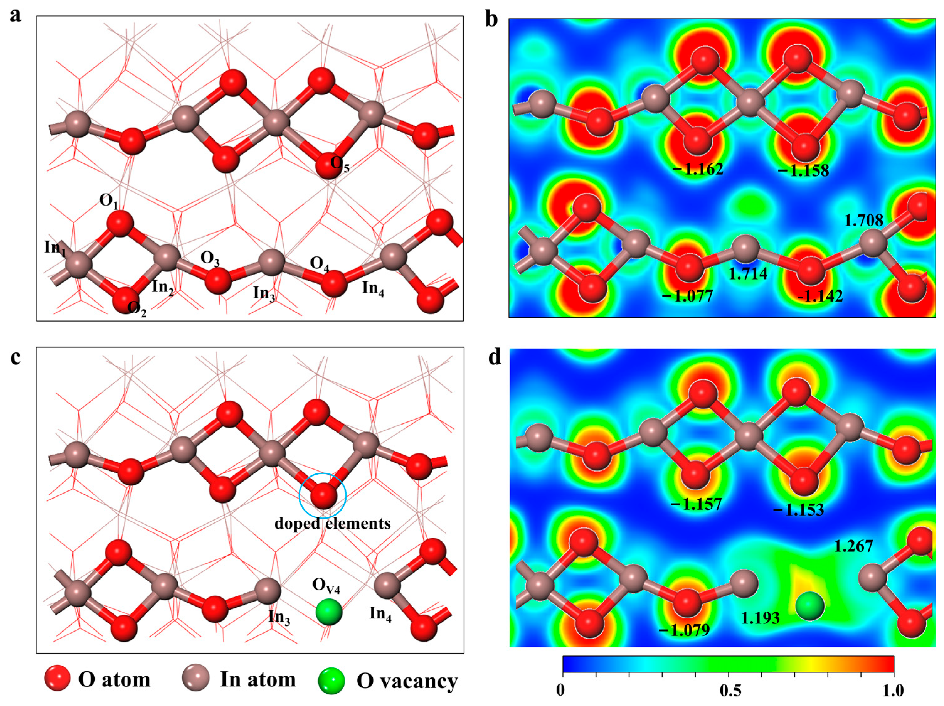
2.1. Geometric Structure of Doping V-In2O3

The surface of In2O3 (110) is one of the major exposed crystal planes of c- In2O3 observed in experiments [18,19,20]. It has also been shown to be thermodynamically stable under electrocatalytic conditions in theoretical studies [21]. Therefore, we chose the surface of In2O3 (110) for our study. The top layer structure of the optimized perfect In2O3 (110) surface is shown in Figure 1a, and consists of 8 In atoms and 12 oxygen atoms forming a repeating unit. In addition, previous reports have shown that oxygen vacancies (VO) on the surface of In2O3 can generate SFLPs sites, which serve as active sites for reactions [22,23,24]. At the same time, Qin et al. calculated the vacancy formation energies of different oxygen vacancies using density functional theory, and the calculations showed that the VO4 site had the highest formation energy [25].
As shown in Figure 1, in the absence of oxygen vacancies on the surface, In3 and In4 atoms (Lewis acids) can form localized structures similar to SFLPs with O atoms (Lewis bases) from the other chain, but the O4 attached to In3 and In4 atoms shields them from their functionality as Lewis acids. The unsaturated ligand In atoms (In4 and In5) and O atoms (O5) on the other chain form SFLPs sites when oxygen vacancies are present on the surface of In2O3 (110) [22,24]. Meanwhile, Bader charge results show that the atomic local charges of In3, In4, and O5 are +1.193 and +1.267, −1.153, respectively. The results show that the creation of oxygen vacancies makes two In atoms (In3 and In4) on the In2O3(110) surface into potential electron donors, further suggesting that oxygen vacancy defects can construct SFLPs sites compared to a perfect In2O3(110) surface. However, the O4 vacancy defects on the surface of In2O3(110) still hold a small charge, which has a shielding effect on the catalytic ability of SFLPs, as can be seen from the electron localization function diagram in Figure 1d.
Indium oxide is a kind of P region elemental material with simple composition which is often used in the catalytic reduction of CO2 at room temperature to synthesize C1 chemicals such as CO and CH3OH. The surface atomic structure of indium-based oxides is easily modified, such as by heteroatom doping to build SFLPs sites. Meanwhile, as far as we know, there have been no investigations on the construction of SFLPs by doping nonmetallic elements on the surface of In2O3. To further enhance the catalytic ability of the SFLPs sites and avoid the shielding effect of oxygen vacancies in different electronic states, we modified the surface by replacing O5 with various nonmetal elements (named n-M@In2O3, nonmetal = C, N, F, Si, P, S, Cl,) and screened for efficient and stable acid-base site combinations in SFLPs. The optimized structure of several nonmetal elements doped in In2O3 (110) is shown in Figure S1. The results of the geometry optimization showed that the different non-metallic elements selected could be used to replace the O5 atom for the modification of the SFLPs site. Subsequently, the stability of the constructed SFLPs site at the actual applied temperature was further tested using 10 ps AIMD simulation for all doped structures. As shown in Figure 2, the curves of the total energy change of the different structures were calculated as the simulation time increased. For C@In2O3 and F@In2O3, the total energy of the system became significantly smaller within the first 1ps of the simulation. Correspondingly, the structure of the surface SFLPs sites changed. The C atom was oxidized to CO and then left the surface, while the F atom moved to the O vacancy and combined with In3 and In4 atoms, also changing the surface SFLPs site structure. Furthermore, although the total energy of B@In2O3 and Si@In2O3 did not change significantly during the simulation, the SFLPs site structure changed. The doped B atoms bound to the oxygen atoms on the surface to break the SFLPs site structure, while the Si atoms filled the original O4 vacancy defect, as well as the doped F atoms. The diagram of the radial distribution function also supported the above results, as can be seen in Figure S2. In general, AIMD simulation results showed that only the doping and substitution of P, S, and Cl atoms could construct relatively stable SFLPs site structures. Therefore, in the following discussion, P@In2O3, S@In2O3, and Cl@In2O3 were selected as research objects to further screen potential and efficient NRR catalysts.

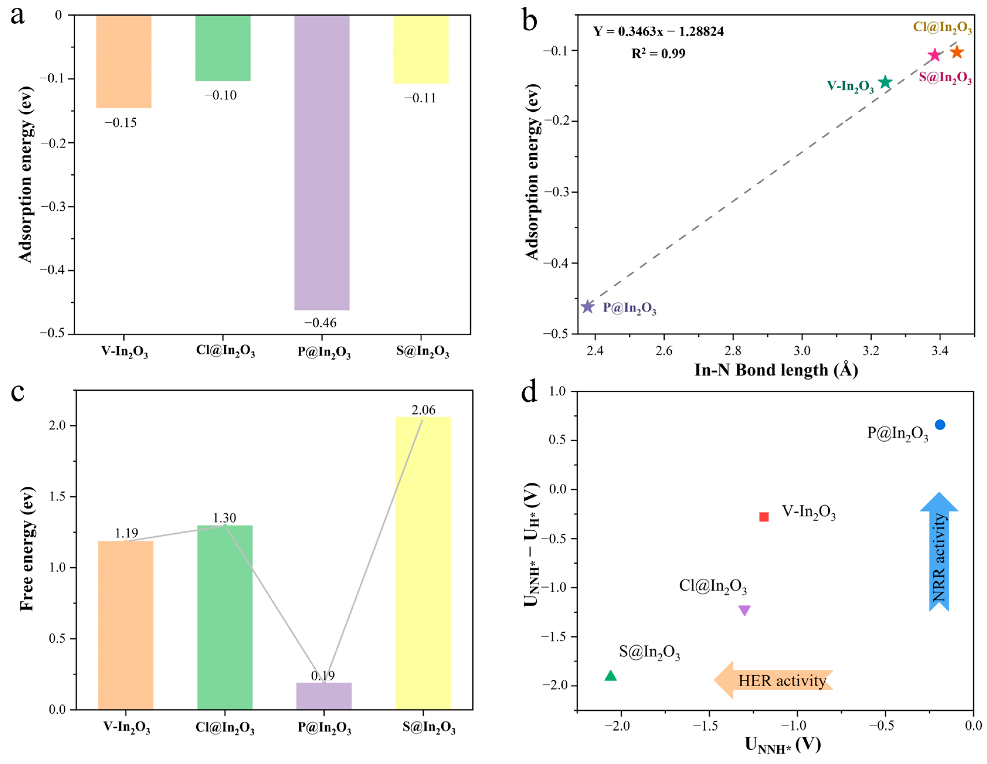
2.2. Adsorption and Protonation of Nitrogen

N2 adsorption is the first and most essential step of the whole NRR process. As shown in Figure S3, the most stable structure of N2 adsorbed on V-In2O3, P@In2O3, S@In2O3, and Cl@In2O3 was optimized. The results show that among the four materials, N2 could be stably adsorbed only on the P@In2O3 surface. Simultaneously, the bond length data of N2 on different materials were summarized in Table S1. The length of the adsorbed N-N bond on P@In2O3 was 1.17 Å, while the length of the free N2 bond was 1.108 Å, indicating that the N-N bond was activated. In addition, the adsorption energy of N2 on different materials was calculated, as shown in Figure 3a. The adsorption energies of N2 on V-In2O3, P@In2O3, S@In2O3, and Cl@In2O3 were −0.15, −0.10, −0.46, and −0.11 eV, respectively. The more negative the adsorption energy, the stronger the adsorption of N2 on the catalysts. The results further showed that P@In2O3 can effectively adsorb N2 molecules. It was also interesting to find that there was a good linear relationship between the bond length of In-N and the adsorption energy of N2, where the shorter the bond length, the stronger the adsorption.
Following the capture and adsorption of N2 molecules, the first hydrogenation step of N2* is critical and is often the potential determining step (PDS) in the protonation step. In addition, the Gibbs free energy (ΔG) of the first hydrogenation of N2* is often used as a descriptor for selecting catalysts with excellent catalytic performance. Therefore, we calculated the ΔG values of N2*→N2H* on V-In2O3, P@In2O3, and S@In2O3. Following the capture and adsorption of N2 molecules, the first hydrogenation step of N2* is critical and is often the potential determining step (PDS) in the protonation step. In addition, the Gibbs free energy (ΔG) of the first hydrogenation of N2* is often used as a descriptor for selecting catalysts with excellent catalytic performance. Therefore, we calculated the ΔG values of N2*→N2H* on V-In2O3, P@In2O3, S@In2O3, and Cl@In2O3 to screen potential NRR catalysts. As can be seen in Figure 3c, the results of the ΔG calculations show that the protonation of N2* on the surfaces of V-In2O3, S@In2O3, and Cl@In2O3 is extremely difficult. However, the free energy of the protonation of N2* on the surface of P@In2O3 is only 0.19 eV, which indicates that P@In2O3 can effectively activate the N-N triple bonds and lower the energy barrier of the protonation of N2*. Therefore, P@In2O3 is selected as a candidate NRR electrocatalyst for further investigation. Under the real conditions of electrocatalysis (in aqueous solution), HER is inevitable as the main side reaction of the NRR system [5,6,7]. As show in Figure S4, the ΔG values of HER for V-In2O3, P@In2O3, S@In2O3, and Cl@In2O3 are −0.91, −0.85, 0.15, and −0.08 eV, respectively. In addition, the potential difference between the N2* protonation and HER processes (UNNH* − UH*) was calculated to evaluate the selectivity of electrocatalysis reactions with different catalysts, as shown in Figure 3d. The results show that P@In2O3 has excellent catalytic selectivity for NRR and can effectively inhibit the HER, which is considered to be a promising electrocatalyst for NRR.

2.3. Catalytic Mechanism in Solution

To explore the reaction mechanism of NRR on P@In2O3, Gibbs free energies of different mechanisms on P@In2O3 and V-In2O3 were calculated and the results are shown in Figure 4. The implicit solvent model was used to consider the influence of the solvation effect on the reaction when calculating the Gibbs free energy diagram. The adsorption and desorption processes are not sensitive to the solvation effect [26], so the calculation started from N2* protonation. The possible NRR pathway on P@In2O3 is shown in Figure 4a, and since N2* is adsorbed on the surface of P@In2O3 in a side-on configuration, the enzymes and distal mechanisms were mainly considered for the NRR process. The results show that the PDS of the enzyme mechanism was NHNH* + H+/e →NH2NH* and ΔG was 0.278 eV, where the PDS of the distal mechanism was NHN*+ H+/e → NH2N* with ΔG of 0.285 eV. It was found that the PDS of the above two mechanism species was not the typical first hydrogenation process, and the protonation steps after PDS were spontaneous processes. At the same time, the limiting potential difference between the two mechanisms was only 0.07 eV, suggesting that NRR can occur on P@In2O3 through both the enzyme and distal mechanisms.
As shown in Figure 4b, the N2 molecule was adsorbed in an end-on configuration on the surface of V-In2O3, so the alternating, distal, and mixed mechanisms are considered. The results show that the PDS of these three reaction mechanisms was the first hydrogenation process (N2*+ H+/e→NNH*) with the ΔG is 1.18 eV. In the case of the mixing mechanism, the protonation steps after the PDS were all processes of energy decrease and could be formed spontaneously. Meanwhile, for the other two mechanisms, the protonation steps after the formation of the first NH3 were all spontaneous processes. It is noteworthy that the NNH* intermediate was not adsorbed at the constructed SFLPs site. Instead, it formed In-N bonds with the two In atoms (In3 and In4) at the oxygen vacancy and was adsorbed on the surface of V-In2O3 by end-on configuration. This also shows that it is not sufficient to build SFLPs sites by oxygen vacancies alone.

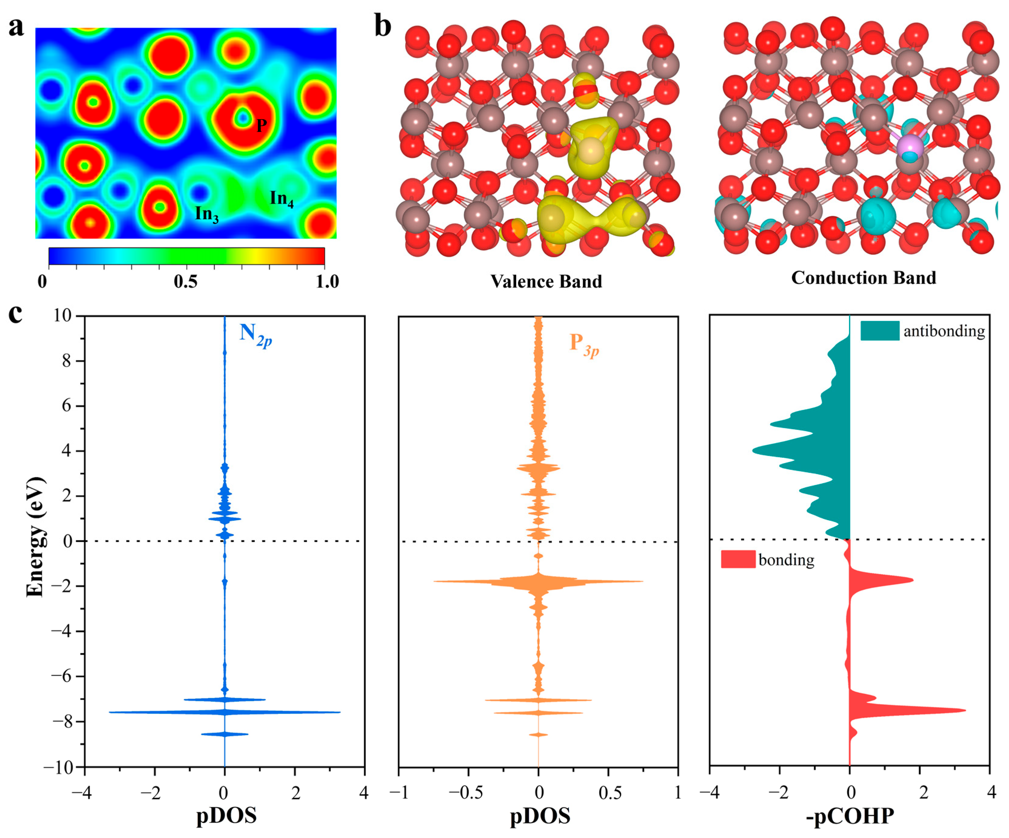
2.4. Origin of Catalytic Activity

In order to identify the origin of catalytic activity at the P-doped SFPLs sites on P@In2O3, the ELF levels of V-In2O3, P@In2O3, S@In2O3, and Cl@In2O3 were calculated and the results are shown in Figure 5 and Figure S6. It can be clearly seen from the figure that there are obvious localization electrons at the oxygen vacancy (between In3 and In4) on the surfaces of V-In2O3, S@In2O3, and Cl@In2O3, while the electron density of the oxygen vacancy on P@In2O3 equals the uniform density of the electron gas. These oxygen vacancies with localization electrons shield the catalytic activity of the constructed SFLPs sites by making it difficult to induce empty orbitals (Lewis acids) from the surrounding metal atoms. Interestingly, the results of partial charge density calculations for the valence band (VB) and conduction band (CB) support this opinion. The partial charge density values of the VB and CB of V-In2O3, P@In2O3, S@In2O3, and Cl@In2O3 are shown in Figure S7. It was found that only the VB of P@In2O3 was mainly contributed by the In atoms (In3 and In4) and the P atoms, whereas the VB of the other results was mainly contributed by the In3 and In4 atoms. As the major constituent in VB, the electron-rich P atom acts as a Lewis base site. It can interact with the empty π orbital of N2, providing electrons to activate N2 molecules. In the meantime, the CB of P@In2O3 is mainly contributed by the In3 atoms. The empty orbital of the In3 atom acts as a Lewis acid site and is able to accept the electron of the N2 molecules. The apparent electron “donation-acceptance” process between the N2 molecules and the SFLPs sites on P@In2O3 promotes the effective activation of the N≡N bonds.
In order to verify the “donation-acceptance” process of the electrons, the difference charge density difference of the N2 adsorbed by the different structures was calculated, as shown in Figure S8. The results show that electron transfer to N2 occurred at the P@In2O3 SFLPs site, which confirms the “donation-acceptance” mechanism of electrons. The Bader charge analysis also confirms this phenomenon and the calculated values in Table S3 indicate that the In3 and P atoms are injected into the N2* molecule. In addition, the integrals of projected crystal orbital Hamilton population (ICOHP) data and bond length data suggest that the SFPLs sites can effectively activate the N≡N bonds, as shown in Tables S1 and S4. At the same time, the partial densities of states (PDOS) and the projected crystal orbital Hamilton population (pCOHP) of N2 adsorbed on different structures were calculated to further investigate the “donation-acceptance” mechanism. As shown in Figure 5c, the 2p orbital of N2 and the 3p orbital of P have a large hybrid region at the high-energy region (−2 eV), and a 2π* orbital of N2 shift to the high-energy region near the Fermi level, indicating strong electron donation interaction and orbital interaction between the P atom and N2. As shown in Figure S9, the bonding orbitals are mainly contributed by the mutual hybridization of the s and p orbitals of the In3 and N atoms between the −6 and −8 eV levels. This shows that the empty 5p orbital of the In atom can effectively accept the σ electron of the N2 molecule and activate the N≡N bonds.

3. Materials and Methods

The DS-PAW program integrated into the Device Studio program [27] was used to perform the calculations under the framework of density functional theory (DFT). The interaction between valence electrons and the ionic core was described using the projection-augmented wave (PAW) base set [28,29], within the exchange-correlation function described by Perdew, Burke, and Ernzerhof (PBE) [30]. The D3 correction method proposed by Grimme [31,32] was used to make up for the deficiency of the GGA functional description of van der Waals interaction. One-electron Kohn−Sham orbitals were expanded with a kinetic energy cutoff of 630 eV. The geometry optimization adopted the 3 × 2 × 1 Monkhorst-Pack grid of the K-points mesh to sample the Brillouin zone. The convergence criterion for self-consistent iteration was set to 1 × 10⁻⁵ eV and the structures were fully relaxed until the final force on each atom was less than 0.03 eV Å−1. To test the stability of the doped structures, Ab initio molecular dynamics (AIMD) simulations of all doping systems were performed using a canonical ensemble (NVT) with Nosé thermostat at 400 K temperature with a total time of 10 ps and a time step of 1 fs. In addition, the density of states (DOS) was calculated using the Vienna Ab initio Simulation Package (VASP) [33,34]. DOS calculations using 4 × 3 × 1 Monkhorst-Pack grids of k-points mesh. At the same time, the LORBSTER [35] program was used to analyze the properties of COHP [36].
In this work, the most thermodynamically stable body-centered cubic bixbyite (c-In2O3) crystal structure was selected, which had undergone extensive theoretical and experimental investigation [19,37,38]. The surface of In2O3 (110) was modeled in a (1 × 2 ) supercell with five periodic atomic layers containing 40 In atoms and 60 O atoms. The bottom three layers of the model were fixed to simulate bulk properties, while the rest of the model was allowed to relax during the geometry optimization process. A vacuum gap of 15 Å was set for all calculations to avoid periodic interactions between the images. The implicit solvent model was used to calculate the Gibbs free energy to consider the solvation effect, and the dielectric constant was set to 78.5 to simulate the aqueous environment.

4. Conclusions

In this study, a series of SFPLs site structures were constructed on the surface of In2O3 by means of a heteroatom doping strategy. Among the eight different structures, P@In2O3, with a stable structure and high catalytic activity, was selected for the electrochemical synthesis of ammonia. The P@In2O3 catalyst could effectively reduce N2 molecules by both enzymatic and distal mechanisms, and it was found that neither mechanism of PDS was a typical first hydrogenation process. Electronic structure analysis shows that the P doping successfully constructed SFPLs sites on the surface of In2O3 and that the In and P atoms were Lewis acid sites and base sites, respectively. The electron-rich P atom (Lewis bases) could interact with the empty π orbital of N2, donating electrons to activate the N2 molecule. Meanwhile, the In atoms with empty orbitals (Lewis acid) could accept the σ electron of the N2 molecule. In summary, this study provides new insights into the reasonable regulation and improvement of the surface structure of P-region elementary materials and provides theoretical guidance for the construction of SFLPs sites.

Supplementary Materials

The following supporting information can be downloaded at: https://www.mdpi.com/article/10.3390/molecules28207130/s1, Figure S1: Optimized structure of (a) perfect In2O3 (110), (b) V-In2O3, (c) B@V-In2O3, and (d) C@V-In2O3, (e) Cl@V-In2O3, (f) F@V-In2O3, (g) P@V-In2O3, (h) S@V-In2O3, (i) Si@V-In2O3; Figure S2: Radial distribution function of (a) perfect In2O3 (110), (b) V-In2O3, (c) B@V-In2O3, and (d) C@V-In2O3, (e) Cl@V-In2O3, (f) F@V-In2O3, (g) P@V-In2O3, (h) S@V-In2O3, (i) Si@V-In2O3; Figure S3: Optimized structure of N2 adsorbed on (a) V-In2O3, (b) P@V-In2O3, (c) S@V-In2O3, and (d) Cl@V-In2O3; Figure S4: The free energy diagram of the HER on different materials. Figure S5: The optimized structure of the HER on (a) V-In2O3, (b) P@V-In2O3, (c) S@V-In2O3, and (d) Cl@V-In2O3; Figure S6: Electron Localization Function of (a) V-In2O3, (b) P@V-In2O3, (c) S@V-In2O3, and (d) Cl@V-In2O3; Figure S7: The Partial charge density of the VB and CB of (a) V-In2O3, (b) P@V-In2O3, (c) S@V-In2O3, and (d) Cl@V-In2O3; Figure S8: The chare density difference of N2 adsorbed on (a) V-In2O3, (b) P@V-In2O3, (c) S@V-In2O3, and (d) Cl@V-In2O3; Figure S9: The -pCOHP between N and In3 atom on P@In2O3 adsorbed N2. Table S1: The partial bond length (Å) of N2 adsorbed on the V-In2O3, P@V-In2O3, S@V-In2O3, and Cl@V-In2O3 ;Table S2: The partial Bader charge of the V-In2O3, P@V-In2O3, S@V-In2O3, and Cl@V-In2O3; Table S3: The partial Bader charge of N2 adsorbed on the V-In2O3, P@V-In2O3, S@V-In2O3, and Cl@V-In2O3; Table S4: The partial Integrals of pCOHP data (-∫pCOHP) of N2 adsorbed on the V-In2O3, P@V-In2O3, S@V-In2O3, and Cl@V-In2O3.

Author Contributions

Conceptualization, M.W. and M.Z.; Methodology, M.Z.; Software, M.Z. and Y.S.; Validation, M.W.; Formal analysis, M.Z. and Y.S.; Investigation, M.W.; Resources, C.L. and X.Z.; Data curation, M.W.; Writing—original draft, M.W., M.Z. and X.Z.; Writing—review & editing, M.Z.; Visualization, Y.S. and C.L.; Supervision, C.L. and X.Z.; Project administration, C.L. and X.Z.; Funding acquisition, C.L. and X.Z. All authors have read and agreed to the published version of the manuscript.

Funding

This work was financially supported by the National Natural Science Foundation of China (52302231 and 21871066), the Natural Science Foundation of Heilongjiang Province in China (Grant No. LH2021B010). and Central Universities the National Natural Science Foundation of China.

Institutional Review Board Statement

Not applicable.

Informed Consent Statement

Not applicable.

Data Availability Statement

Not applicable.

Acknowledgments

We gratefully acknowledge HZWTECH for providing computation facilities.

Conflicts of Interest

The authors declare no conflict of interest.

Sample Availability

Not applicable.

References

  1. Cui, X.; Tang, C.; Zhang, Q. A Review of Electrocatalytic Reduction of Dinitrogen to Ammonia under Ambient Conditions. Adv. Energy Mater. 2018, 8, 1800369. [Google Scholar] [CrossRef]
  2. Shi, L.; Yin, Y.; Wang, S.; Sun, H. Rational Catalyst Design for N2 Reduction under Ambient Conditions: Strategies toward Enhanced Conversion Efficiency. ACS Catal. 2020, 10, 6870–6899. [Google Scholar] [CrossRef]
  3. Zhu, X.; Mou, S.; Peng, Q.; Liu, Q.; Luo, Y.; Chen, G.; Gao, S.; Sun, X. Aqueous electrocatalytic N2 reduction for ambient NH3 synthesis: Recent advances in catalyst development and performance improvement. J. Mater. Chem. A 2020, 8, 1545–1556. [Google Scholar] [CrossRef]
  4. Wan, Y.; Xu, J.; Lv, R. Heterogeneous electrocatalysts design for nitrogen reduction reaction under ambient conditions. Mater. Today 2019, 27, 69–90. [Google Scholar] [CrossRef]
  5. Huang, Z.; Rafiq, M.; Woldu, A.R.; Tong, Q.-X.; Astruc, D.; Hu, L. Recent progress in electrocatalytic nitrogen reduction to ammonia (NRR). Coord. Chem. Rev. 2023, 478, 214981. [Google Scholar] [CrossRef]
  6. Zhao, X.; Hu, G.; Chen, G.-F.; Zhang, H.; Zhang, S.; Wang, H. Comprehensive Understanding of the Thriving Ambient Electrochemical Nitrogen Reduction Reaction. Adv. Mater. 2021, 33, 2007650. [Google Scholar] [CrossRef] [PubMed]
  7. Lee, C.; Yan, Q. Electrochemical reduction of nitrogen to ammonia: Progress, challenges and future outlook. Curr. Opin. Electrochem. 2021, 29, 100808. [Google Scholar] [CrossRef]
  8. Légaré, M.-A.; Bélanger-Chabot, G.; Dewhurst, R.D.; Welz, E.; Krummenacher, I.; Engels, B.; Braunschweig, H. Nitrogen fixation and reduction at boron. Science 2018, 359, 896–900. [Google Scholar] [CrossRef] [PubMed]
  9. Liu, Y.; Li, Q.; Guo, X.; Kong, X.; Ke, J.; Chi, M.; Li, Q.; Geng, Z.; Zeng, J. A Highly Efficient Metal-Free Electrocatalyst of F-Doped Porous Carbon toward N2 Electroreduction. Adv. Mater. 2020, 32, 1907690. [Google Scholar] [CrossRef]
  10. Lv, C.; Zhong, L.; Yao, Y.; Liu, D.; Kong, Y.; Jin, X.; Fang, Z.; Xu, W.; Yan, C.; Dinh, K.N.; et al. Boosting Electrocatalytic Ammonia Production through Mimicking “π Back-Donation”. Chem 2020, 6, 2690–2702. [Google Scholar] [CrossRef]
  11. Yuan, M.; Chen, J.; Xu, Y.; Liu, R.; Zhao, T.; Zhang, J.; Ren, Z.; Liu, Z.; Streb, C.; He, H.; et al. Highly selective electroreduction of N2 and CO2 to urea over artificial frustrated Lewis pairs. Energy Environ. Sci. 2021, 14, 6605–6615. [Google Scholar] [CrossRef]
  12. Lin, W.; Chen, H.; Lin, G.; Yao, S.; Zhang, Z.; Qi, J.; Jing, M.; Song, W.; Li, J.; Liu, X.; et al. Creating Frustrated Lewis Pairs in Defective Boron Carbon Nitride for Electrocatalytic Nitrogen Reduction to Ammonia. Angew. Chem. Int. Ed. 2022, 61, e202207807. [Google Scholar] [CrossRef]
  13. Wang, Z.; Zhou, Y.; Liu, D.; Qi, R.; Xia, C.; Li, M.; You, B.; Xia, B.Y. Carbon-Confined Indium Oxides for Efficient Carbon Dioxide Reduction in a Solid-State Electrolyte Flow Cell. Angew. Chem. Int. Ed. 2022, 61, e202200552. [Google Scholar] [CrossRef] [PubMed]
  14. Wang, L.; Ghoussoub, M.; Wang, H.; Shao, Y.; Sun, W.; Tountas, A.A.; Wood, T.E.; Li, H.; Loh, J.Y.Y.; Dong, Y.; et al. Photocatalytic Hydrogenation of Carbon Dioxide with High Selectivity to Methanol at Atmospheric Pressure. Joule 2018, 2, 1369–1381. [Google Scholar] [CrossRef]
  15. Du, X.; Qin, Y.; Gao, B.; Wang, K.; Li, D.; Li, Y.; Ding, S.; Song, Z.; Su, Y.; Xiao, C. Plasma-assisted and oxygen vacancy-engineered In2O3 films for enhanced electrochemical reduction of CO2. Appl. Surf. Sci. 2021, 563, 150405. [Google Scholar] [CrossRef]
  16. Dostagir, N.H.M.D.; Thompson, C.; Kobayashi, H.; Karim, A.M.; Fukuoka, A.; Shrotri, A. Rh promoted In2O3 as a highly active catalyst for CO2 hydrogenation to methanol. Catal. Sci. Technol. 2020, 10, 8196–8202. [Google Scholar] [CrossRef]
  17. Ye, J.; Liu, C.; Mei, D.; Ge, Q. Active Oxygen Vacancy Site for Methanol Synthesis from CO2 Hydrogenation on In2O3(110): A DFT Study. ACS Catal. 2013, 3, 1296–1306. [Google Scholar] [CrossRef]
  18. Agoston, P.; Albe, K. Thermodynamic stability, stoichiometry, and electronic structure of bcc- In2O3 surfaces. Phys. Rev. B 2011, 84, 045311. [Google Scholar] [CrossRef]
  19. Walsh, A.; Catlow, C.R.A. Structure, stability and work functions of the low index surfaces of pure indium oxide and Sn-doped indium oxide (ITO) from density functional theory. J. Mater. Chem. 2010, 20, 10438–10444. [Google Scholar] [CrossRef]
  20. Hagleitner, D.R.; Menhart, M.; Jacobson, P.; Blomberg, S.; Schulte, K.; Lundgren, E.; Kubicek, M.; Fleig, J.; Kubel, F.; Puls, C.; et al. Bulk and surface characterization of In2O3 (001) single crystals. Phys. Rev. B 2012, 85, 115441. [Google Scholar] [CrossRef]
  21. Zhang, M.; Wang, W.; Chen, Y. Insight of DFT and ab initio atomistic thermodynamics on the surface stability and morphology of In2O3. Appl. Surf. Sci. 2018, 434, 1344–1352. [Google Scholar] [CrossRef]
  22. Yan, T.; Li, N.; Wang, L.; Ran, W.; Duchesne, P.N.; Wan, L.; Nguyen, N.T.; Wang, L.; Xia, M.; Ozin, G.A. Bismuth atom tailoring of indium oxide surface frustrated Lewis pairs boosts heterogeneous CO2 photocatalytic hydrogenation. Nat. Commun. 2020, 11, 6095. [Google Scholar] [CrossRef] [PubMed]
  23. Yuan, M.; Zhang, H.; Xu, Y.; Liu, R.; Wang, R.; Zhao, T.; Zhang, J.; Liu, Z.; He, H.; Yang, C.; et al. Artificial frustrated Lewis pairs facilitating the electrochemical N2 and CO2 conversion to urea. Chem Catal. 2022, 2, 309–320. [Google Scholar] [CrossRef]
  24. Wang, L.; Yan, T.; Song, R.; Sun, W.; Dong, Y.; Guo, J.; Zhang, Z.; Wang, X.; Ozin, G.A. Room-Temperature Activation of H2 by a Surface Frustrated Lewis Pair. Angew. Chem. Int. Ed. 2019, 58, 9501–9505. [Google Scholar] [CrossRef] [PubMed]
  25. Qin, B.; Li, S. First principles investigation of dissociative adsorption of H2 during CO2 hydrogenation over cubic and hexagonal In2O3 catalysts. Phys. Chem. Chem. Phys. 2020, 22, 3390–3399. [Google Scholar] [CrossRef] [PubMed]
  26. Sun, Y.; Shi, W.; Fu, Y.-Q.; Yu, H.; Wang, Z.; Li, Z. The novel π–d conjugated TM2B3N3S6 (TM = Mo, Ti and W) monolayers as highly active single-atom catalysts for electrocatalytic synthesis of ammonia. J. Colloid Interface Sci. 2023, 650, 1–12. [Google Scholar] [CrossRef]
  27. Hongzhiwei Technology, Device Studio, Version 2021A, China. 2021. Available online: https://iresearch.net.cn/cloud-software (accessed on 15 October 2023).
  28. Kresse, G.; Joubert, D. From ultrasoft pseudopotentials to the projector augmented-wave method. Phys. Rev. B 1999, 59, 1758–1775. [Google Scholar]
  29. Blochl, P.E. Projector Augmented-Wave Method. Phys. Rev. B 1994, 50, 17953–17979. [Google Scholar] [CrossRef]
  30. Perdew, J.P.; Burke, K.; Ernzerhof, M. Generalized Gradient Approximation Made Simple. Phys. Rev. Lett. 1996, 77, 3865–3868. [Google Scholar] [CrossRef]
  31. Grimme, S.; Ehrlich, S.; Goerigk, L. Effect of the Damping Function in Dispersion Corrected Density Functional Theory. J. Comput. Chem. 2011, 32, 1456–1465. [Google Scholar] [CrossRef] [PubMed]
  32. Grimme, S.; Antony, J.; Ehrlich, S.; Krieg, H. A consistent and accurate ab initio parametrization of density functional dispersion correction (DFT-D) for the 94 elements H-Pu. J. Chem. Phys. 2010, 132, 154104. [Google Scholar] [CrossRef] [PubMed]
  33. Hafner, J. Ab-initio simulations of materials using VASP: Density-functional theory and beyond. J. Comput. Chem. 2008, 29, 2044–2078. [Google Scholar] [CrossRef] [PubMed]
  34. Kresse, G.; Furthmüller, J. Efficient iterative schemes for ab initio total-energy calculations using a plane-wave basis set. Phys. Rev. B 1996, 54, 11169–11186. [Google Scholar] [CrossRef] [PubMed]
  35. Maintz, S.; Deringer, V.L.; Tchougreeff, A.L.; Dronskowski, R. LOBSTER: A Tool to Extract Chemical Bonding from Plane-Wave Based DFT. J. Comput. Chem. 2016, 37, 1030–1035. [Google Scholar] [CrossRef] [PubMed]
  36. Dronskowski, R.; Bloechl, P.E. Crystal orbital Hamilton populations (COHP): Energy-resolved visualization of chemical bonding in solids based on density-functional calculations. J. Phys. Chem. 1993, 97, 8617–8624. [Google Scholar] [CrossRef]
  37. Wang, W.; Chen, Y.; Zhang, M. Facet effect of In2O3 for methanol synthesis by CO2 hydrogenation: A mechanistic and kinetic study. Surf. Interfaces 2021, 25, 101244. [Google Scholar] [CrossRef]
  38. Ye, J.; Liu, C.; Ge, Q. DFT Study of CO2 Adsorption and Hydrogenation on the In2O3 Surface. J. Phys. Chem. C 2012, 116, 7817–7825. [Google Scholar] [CrossRef]
Figure 1. Optimized structure of (a) the perfect In2O3 (110) surface and (c) defective In2O3 (110) with one oxygen vacancy. Electron localization function of (b) the perfect In2O3 (110) surface and (d) defective In2O3 (110) with one oxygen vacancy. The black numbers in the diagram are the Bader charges of the atoms.
Molecules 28 07130 g001
Figure 2. Variations in temperature and energy against the time for the AIMD simulations of (a) V-In2O3, (b) B@In2O3, (c) C@In2O3, (d) Cl@In2O3, (e) F@In2O3, (f) P@In2O3, (g) S@In2O3, and (h) Si@In2O3. The simulation was run under 400 K for 10ps with a time step of 1 fs.
Molecules 28 07130 g002
Figure 3. (a) Adsorption energy of N2 on different materials. (b) The adsorption energy of N2 on different materials is a function of the In-N bond length. (c) The free energy of the first hydrogenation of N2 on different materials. (d) Diagram of the potential difference between the NRR and HER on different materials.
Molecules 28 07130 g003
Figure 4. Gibbs free energy diagrams and intermediate structure of N2 reduction process on (a) P@In2O3 and (b) V-In2O3.
Molecules 28 07130 g004
Figure 5. (a) Electron localization function and (b) partial charge density of the VB and CB of P@In2O3. The value of the isosurface is 0.002 e/Å−3. (c) The pDOS and -pCOHP between N and P atoms on P@In2O3-adsorbed N2.
Molecules 28 07130 g005
Disclaimer/Publisher’s Note: The statements, opinions and data contained in all publications are solely those of the individual author(s) and contributor(s) and not of MDPI and/or the editor(s). MDPI and/or the editor(s) disclaim responsibility for any injury to people or property resulting from any ideas, methods, instructions or products referred to in the content.

