1. Introduction
Rechargeable batteries are not as rechargeable as we often would like to believe. When a battery is charged or discharged with a non-zero current, all sorts of unfavorable gradients set in. These include temperature gradients, concentrations gradients, voltage gradients and current gradients. They form over complex interfaces in the battery cell, between electrodes and electrolyte, between conductors and electrode materials, between the charged and discharged parts of the electrode, etc. These gradients drive a variety of unwanted and complicated interconnected parasitic side reactions. The inability to fully reverse all the parasitic reactions is a prerequisite for creating a chaotic system, and this will tend to make rechargeable batteries unstable with respect to charge/discharging. Cycling rechargeable batteries have something in common with forecasting weather, in that it works well in the beginning but gets progressively more difficult the further it goes. This difficulty is also reflected in the very few numbers of commercially successful rechargeable battery chemistries developed over time. In the mid-nineteenth century, the common lead–acid chemistry was developed. The two electrode materials were lead metal and lead oxide, both forming lead sulfate with sulfuric acid electrolyte during discharge, i.e., heavy and poisonous—why not select more convenient materials as almost any redox reaction can be made into an electrochemical cell? The answer is that it is very difficult to find a reversible redox reaction that is free of troublesome parasitic side reactions. We had to wait 50 years until the beginning of the last century for the nickel–iron (NiFe) battery to appear, also known as the Edison battery. Unfortunately, the iron electrode had a side reaction, forming hydrogen gas during charge. This side reaction consumed the alkaline electrolyte, making it necessary to frequent refill the battery electrolyte. Different additives were tested to mitigate the hydrogen-producing side reaction, one of which was cadmium (Cd). In the end, all iron was substituted with Cd, and the NiCd battery was created. Today, the volume of NiFe battery production volume is limited. The NiCd battery is a well-functioning battery, yet cadmium is considered a poisonous metal and there are restrictions regarding its use. Another limitation is that cadmium is a fairly rare element. The global production of cadmium is only slightly larger than that of silver. Hence, after 50 years of development, we still had only two commercially successful rechargeable battery chemistries, both of which are based on troublesome metals. Then, we had to wait almost another century for the next successful rechargeable battery chemistries: first, nickel–metal hydride, (NiMH) and, a few years later, Li batteries. NiMH was made possible by the discovery of certain hydrogen storage alloys that could store hydrogen in the interstitial sites of the alloys without forming overly strong metal–hydrogen bonds [
1]. Thus, a solid-state hydrogen electrode could be created. The Ni electrode was the same as in the NiCd battery. The NiMH battery chemistry is, however, simpler than the NiCd chemistry in that hydrogen is directly available at the metal hydride alloy surface. In the NiCd battery hydrogen has to be created by corroding the cadmium metal in the alkaline electrolyte. This facilitates the construction of the NiMH cell as the volume of the electrolyte is constant over the charge/discharge cycle in the NiMH cell in contrast to the NiCd cell [
1]. The Li cell has a few things in common with the NiMH cell. Both have electrodes based on intercalation reactions and no dissolution/precipitation reactions, as is the case for lead–acid and NiCd batteries. This opens up for easier control of parasitic reactions and, thus, for a possible long cycle life for both new battery chemistries. In the NiMH cell, hydrogen is shuttled between the electrodes. In the Li cell, lithium is doing the same. In the charged state, hydrogen is stored as a metallic hydride in the NiMH cell, while in the Li cell, lithium is usually stored in graphite or coke. When the cells are discharged, hydrogen and lithium are transferred to the counter electrodes consisting of transition metal oxides. In the NiMH cell, they were nickel oxide, and for the first commercial Li cells, they were cobalt oxide. In oxygen-containing electrodes, the hydrogen and lithium are firmly bonded as H
+ and Li
+ ions. It is essentially these bonds that contain the stored energy in the cells. The stronger bond in the Li battery compared to the oxygen–hydrogen bond in the NiMH battery gives the Li battery the benefit of having a three times higher voltage, approximately 3.7 V compared to 1.25 V for the NiMH cell. However, the Li cell capacity is not three times higher as the metal hydride electrode can store a high density of hydrogen atoms. The lower voltage in the NiMH battery brings advantages as it allows the use of a highly conducting water-based alkaline electrolyte, which also simplifies the choice of separator. In the Li cell, non-aqueous electrolytes with significantly poorer conductivity have to be used, forcing the separator to be very thin to compensate for the poor conductivity. The micron-thin separator that separates the highly reactive electrode materials leads to stringent quality demands for safety reasons. The presence of hydrogen in the metal hydride electrode further mitigates corrosion of the hydrogen storage alloy. If hydrogen in the NiMH cell is corroded, it forms water, which is the base for the electrolyte. In the Li cell, on the other hand, the very reactive lithium itself is prone to corroding and forming insolvable species with a negative influence on performance.
As explained later, we showed that the good corrosion stability of the metal hydride alloy could be used to multiply the cycle life of NiMH cells by the addition of oxygen and hydrogen gas [
2]. This will make NiMH batteries more competitive in relation to Li batteries. The high capacity of Li batteries is certainly a big advantage but, in many applications, it is more important to both store and deliver a high amount of energy throughout the battery lifetime. This means that capacity times cycle life will be an important parameter when comparing batteries. Another issue to compare is how easy it is to recycle the used batteries. In the present article, it is suggested that the good corrosion stability of the MH alloy can be turned into a very simple recycling process based on a simple mechanical washing and rinsing process.
Modern metal hydride (NiMH) battery alloys are produced by a series of processes that have been continuously developed since NiMH batteries were commercialized at the beginning of the 1990s. The metals are melted and mixed in a crucible held under a protective atmosphere, while composition and temperature are carefully controlled. The alloy is then cast in a rapid solidification process. More recently, this has started to be done by strip casting. Finally, an annealing step is applied to promote uniformity before the final alloy is pulverized and sieved. The development of these processes over time has resulted in robust and corrosion-resistant metal hydride storage alloys for NiMH batteries. Despite the development of new and improved materials, the corrosion of the metal hydride is still indirectly detrimental for life expectancy, as the corrosion consumes the aqueous electrolyte. The loss of electrolyte increases the internal resistance, making the cells incapable of working at high currents. This is aggravated by the fact that the cells are filled with a very limited amount of electrolyte in order to allow oxygen and hydrogen gas to pass between the electrodes through openings in the porous separator. This facilitates overcharge and over-discharge protection reactions via the gas phase. The arrangement is usually called “a starved electrolyte concept” [
1,
2].
When the cell is charged, Ni(II)(OH)
2 is converted to Ni(III)OOH and hydrogen is transferred from the Ni electrode to the MH electrode in the form of water molecules after reacting with OH
− ions. When the 2-valent Ni(OH)
2 is depleted of available hydrogen, the cell goes into an overcharge mode, and hydrogen is taken from the electrolyte, leading to oxygen gas evolution at the Ni electrode. If the separator between the electrodes is not completely filled with electrolyte, the oxygen molecules can pass through open channels in the separator and recombine with hydrogen to form water at the metal hydride electrode. This leads to a steady-state charge level and a temperature rise, which can be detected and used for terminating the charge. When the cell is discharged, OH
− ions react with hydrogen from the metal hydride forming a water molecule. Concomitant at the Ni electrode a water molecule will be deprived from a hydrogen atom reforming Ni(II)(OH)
2 and an OH
− ion. When the cell is over-discharged and the Ni(OH)
2 cannot accept more hydrogen, a similar process will recombine gaseous hydrogen into water. Both these recombination reactions mitigate the pressure increase in the cells and prevent the safety valve from opening, which can lead to an accelerated loss of electrolyte. The corrosion of the metal hydride alloys by the alkaline electrolyte, however, also evolves H
2 gas when the metals form hydroxides in the corrosion process. When this hydrogen is absorbed in the MH electrode, it shifts the electrode balance in the cells, exhausting the overcharge reserve. This causes the overcharge reactions to stop working and if the pressure increases and vents through the safety valve, the cells quickly dry out [
3].
Initial corrosion is, however, necessary for creating an active surface that can promote the kinetics of the electrode reactions. Most NiMH batteries are based on LaNi
5 or La(Mg)Ni
7 derivatives, commonly labeled AB
5- or A
2B
7-type alloys [
4]. A is a mixture of electropositive metals, usually dominated by rare-earth (RE) metal mixtures corresponding to the composition of the source from where it is mined. B is essentially Ni partly substituted by Co, Mn, and Al to adjust the hydrogen uptake and release properties. The corrosion of the alloy yields needle-like crystals of RE hydroxide adhered to the outermost surface. A denser underlying surface coating acts as an interphase between the electrolyte protecting the inner metallic part of the alloy particle. This protective interphase also holds nickel-containing nano-sized clusters formed during the initial corrosion. The clusters are important for the catalytic activity promoting the making and breaking of O–H bonds during discharge and charge, respectively [
5,
6].
It is, however, also important that the protective coating is stable against further corrosion, so it can continue to protect the inner metallic part that stores hydrogen [
2]. In a recent paper, it was confirmed that the corrosion protection by the initial corrosion during cycling is actually rather effective [
2]. The drying out of the cells was mitigated by adding pure oxygen gas to an aged NiMH battery pack, to see if the oxygen could react with the hydrogen liberated in the preceding corrosion process. This worked well, as the oxygen reacted with hydrogen without corroding the metals, forming water that could replenish the electrolyte. The oxygen addition also reestablishes the electrode balance. The performance of the used battery recovered with respect to internal resistance and capacity because of the replenished electrolyte. This indicated that most of the alloy is well-protected by the surface in a spent NiMH battery after the battery has reached its end of life [
2]. In another recent paper, the presence of rare-earth metals was suggested as a reason for the beneficial corrosion stability [
7]. This provided the inspiration for trying a new method for regeneration of MH electrode materials by simply cleaning and washing the powder surfaces. Thus, energy-consuming resmelting and recasting of MH alloys could be avoided, as well as complicated chemical-consuming hydrometallurgical processes used in conventional recycling of battery materials.
In this work, discharged bipolar NiMH 12-volt battery modules produced by Nilar AB in Sweden were disassembled, and the spent MH electrodes after the modules had been in use for long-term testing were collected. Nilar makes MH electrodes by pressing a dry mixture of hydrogen storage alloy and Ni powder on to a polymeric carrier. No substrates such as Ni-foam or expanded metal are used. This facilitates a simple retrieval of the electrode materials.
To recover the performance of the spent alloy, mechanical as well as chemical treatments were tested in an effort to remove the corrosion products. Mechanically, sonification and ball milling combined with a simple washing of the resulting mixture were tested.
Sonication provides a flexible way of treating a system with respect to time of interaction, pressure, and applied energy [
8]. With a high-power ultrasonic source these characteristics are even further emphasized, making it an interesting tool. As suggested by Chen et al., it may be possible to work upon the hydroxide layer by sonication of either the complete battery cells or, for selective regeneration, the MH electrode material itself [
9].
The chemical treatments were composed of washing with acidic or alkaline solutions. As RE hydroxides can be dissolved by acidic solvents, acid treatment is a possible way to remove the passivating RE hydroxide layer. Sulfuric acid leaching has been used for RE recovery from spent NiMH batteries [
10,
11,
12]. It is, however, a complicated process. Here, a low-concentration sulfuric acid solution was tested for the removal of the corrosion layer from the bulk alloy. The dissolution of the RE hydroxides can be described as:
Hot alkaline treatments have been found to improve the electrochemical performance of AB2 and AB5-type hydrogen story alloys [
13,
14]. Therefore, there is the possibility of washing away the hydroxide layer by cooking in a hot alkaline solution.
2. Result and Discussion
The rare-earth hydroxide needles formed on the MH particles can be removed by sonication.
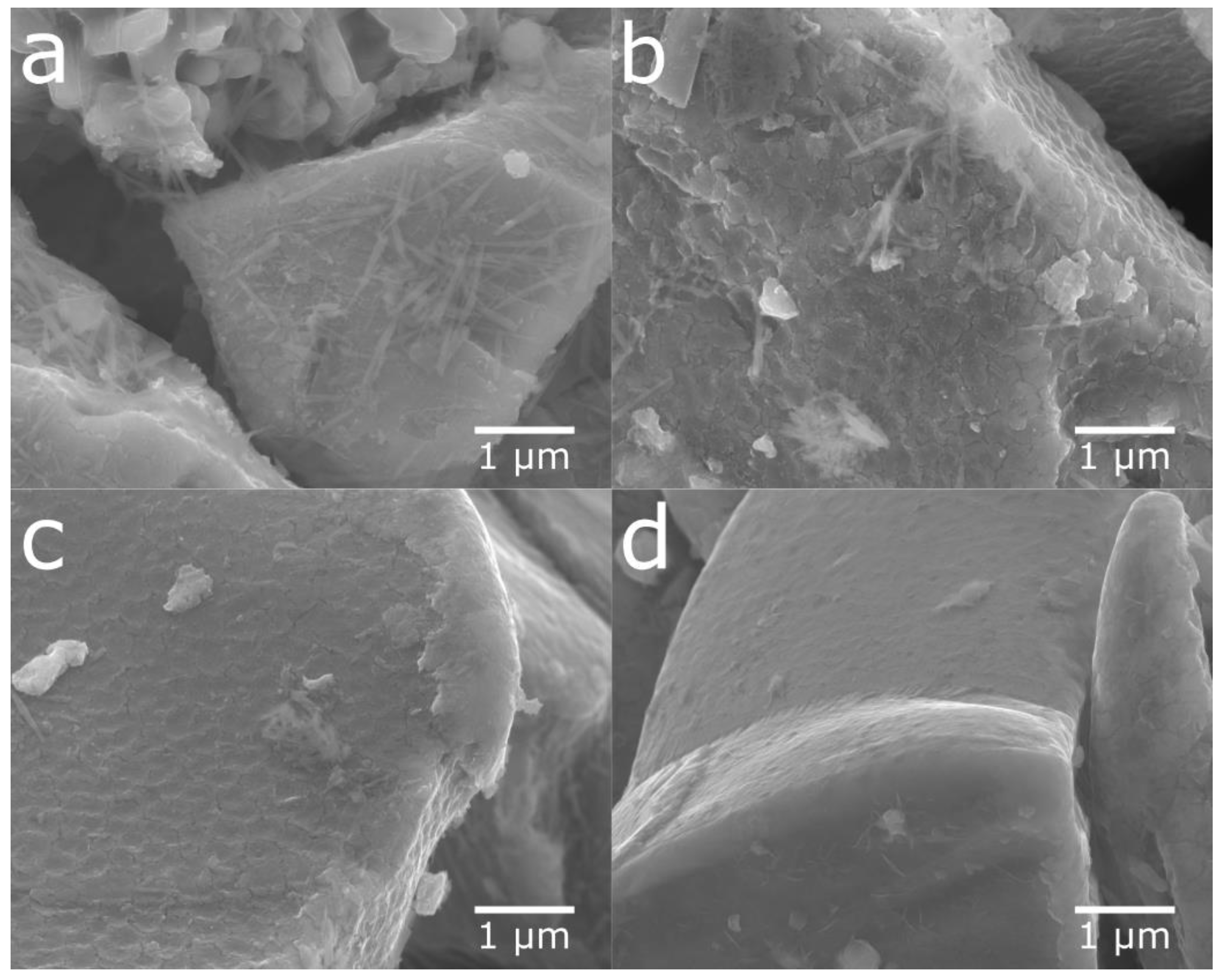
Figure 1 shows the SEM images of the cycled and sonotrode-sonicated samples. After 2 h of sonication, the alloy showed a very clean surface.
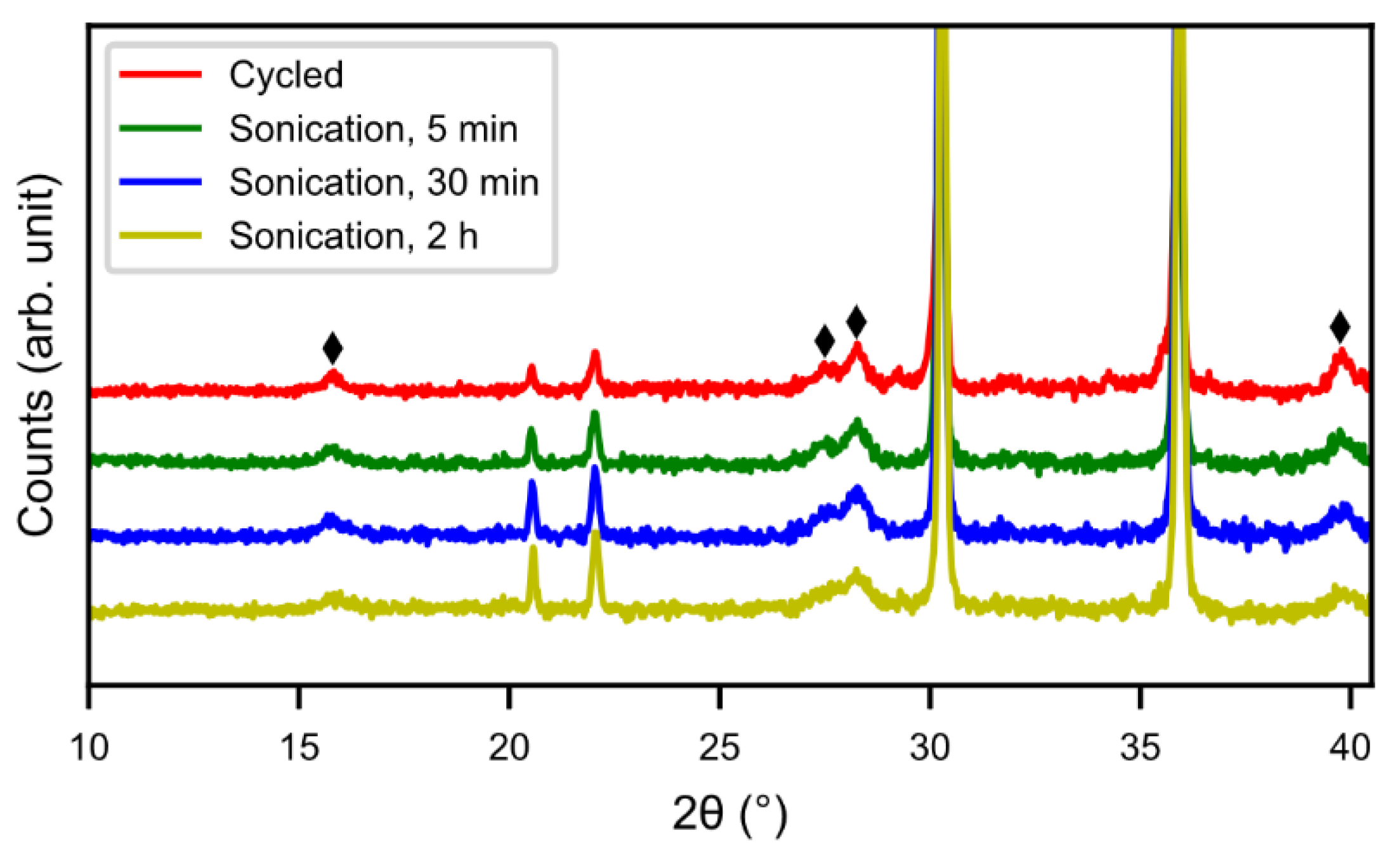
Figure 2 shows X-ray diffraction patterns of cycled alloy and sonotrode-sonicated alloys. With increasing sonication time the peaks of rare-earth hydroxide decreased. The peaks were, however, still present even if the Mm(OH)
3 needles were not observed in the SEM. This indicates that a bulk hydroxide interphase formed underneath the needles remains. From
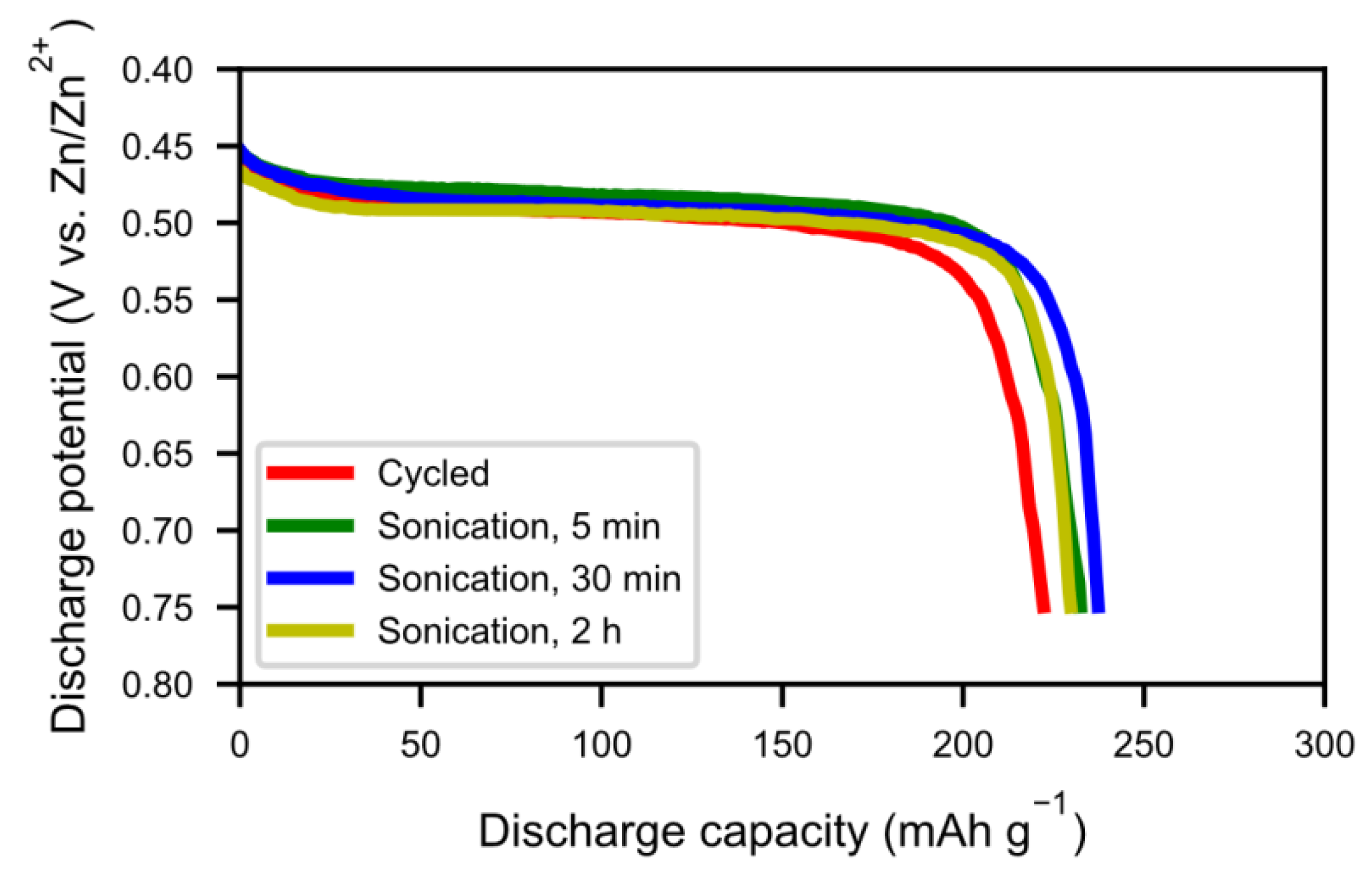
Figure 3, the half-cell test shows an optimum in capacity (~240 mAh g
−1) for the sample with 30 min of sonication, however, the discrepancy is still large when compared to the fresh alloy, which had a capacity around 320 mAh g
−1 [
5]. This is probably due to a thicker interphase covering the surface as the corrosion-resistance of the alloy is lower. The sample with 2 h of sonication showed a lower capacity, possibly due to a passivation of the active catalytic species in the interphase.
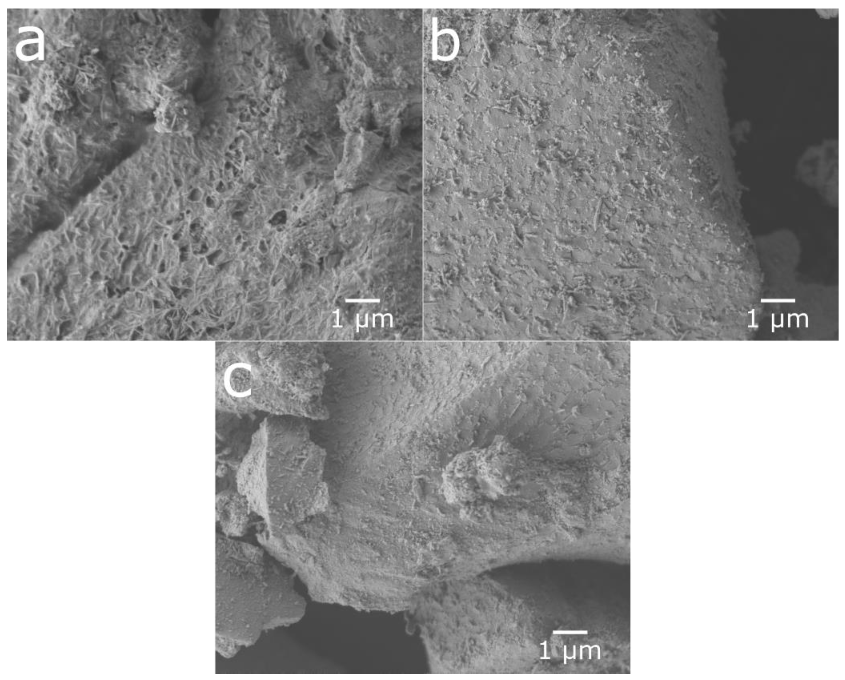
Inspired by this, large-scale sonication in an ultrasonic bath with a lower power input than the sonotrode was tested, with the aim of sparing the catalytic properties. Additionally, a mild ball-milling procedure was tested.
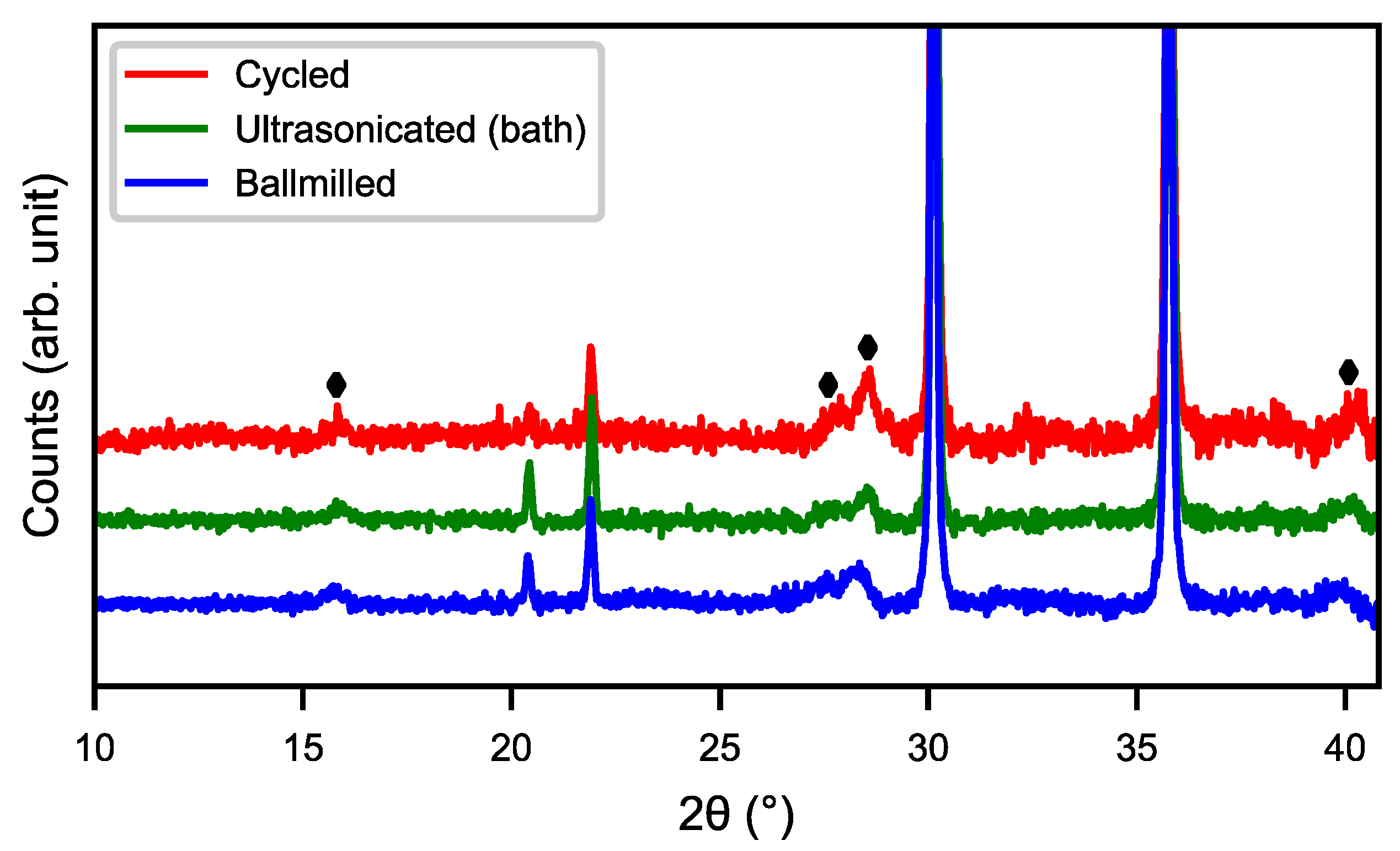
Figure 4 shows the SEM images of cycled, ultrasonicated, and ball-milled material. After the ultrasonic bath, the material had a relatively smooth surface with an overlay of small particle fragments as well as some needle-like structures. The ball-milled material showed a very similar surface to that of the ultra-sonicated sample, but with smaller particle fragments and needle-shaped structures partially covering the surface. This indicates that the rare-earth hydroxide layer can be partly removed in an ultrasonic bath as well as by ball-milling, as shown in
Figure 5, where the peaks of rare-earth hydroxide slightly decrease after treatments.
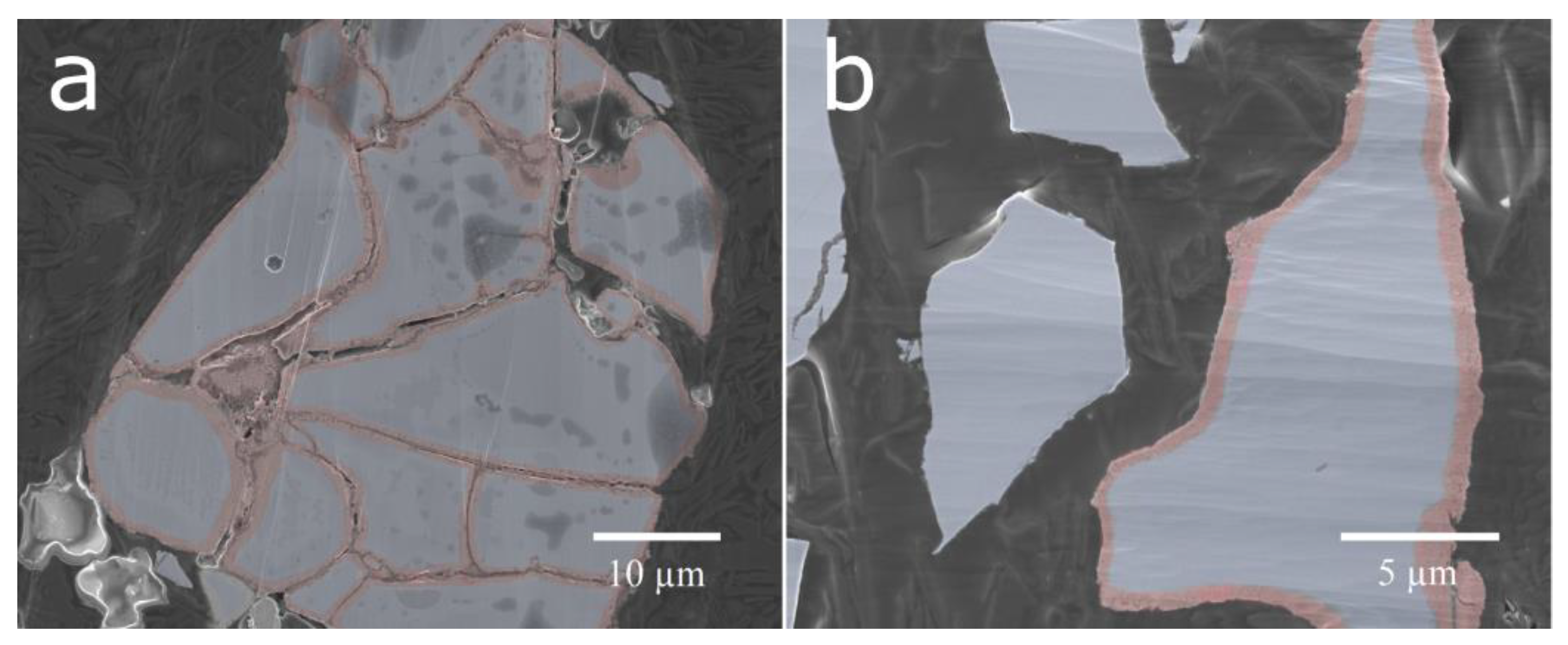
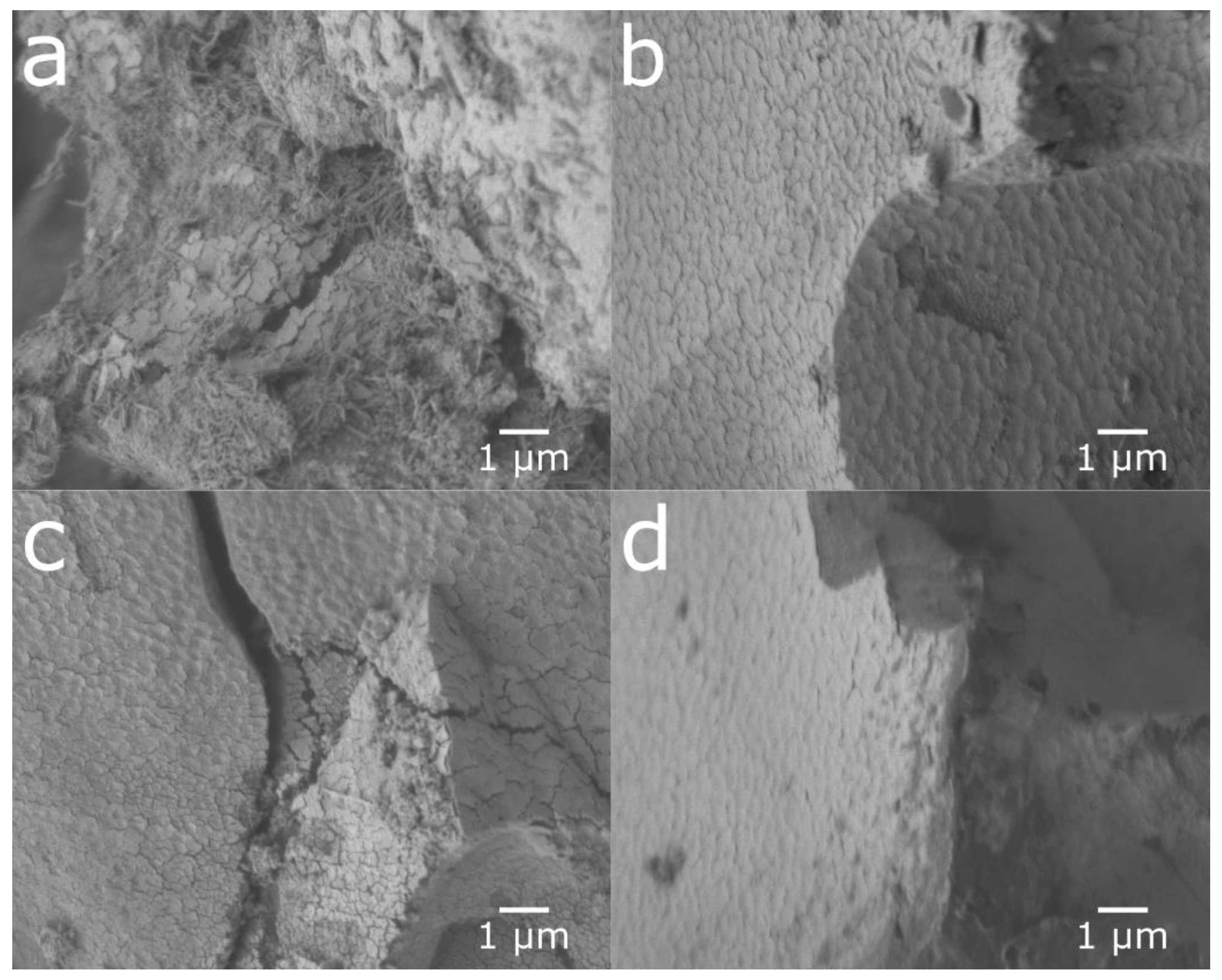
Cross-sections of the untreated cycled material and the ball-milled material were prepared (
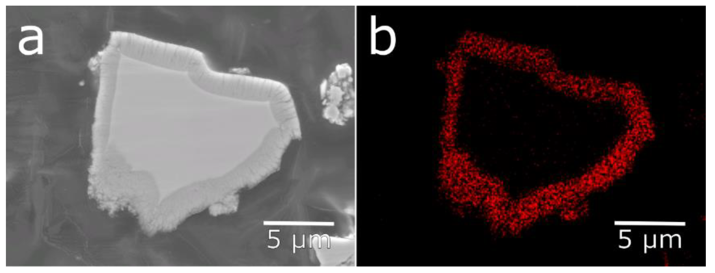
Figure 6). The ball-milled material showed a mixture of particles with fresh surfaces from particles cracked in the ball-milling and corroded surfaces, where the ball-milling had just separated the particles and removed most of the rare-earth hydroxide needles. This contrasts with the cycled material, where a corrosion layer could be seen on all surfaces throughout both fissures and the exterior. The surface layer observed on the corroded particles was determined to be oxygen-rich by EDS mapping (
Figure 7). This oxygen-rich structure is most likely, as previously shown, made up of rare-earth hydroxides [
5].
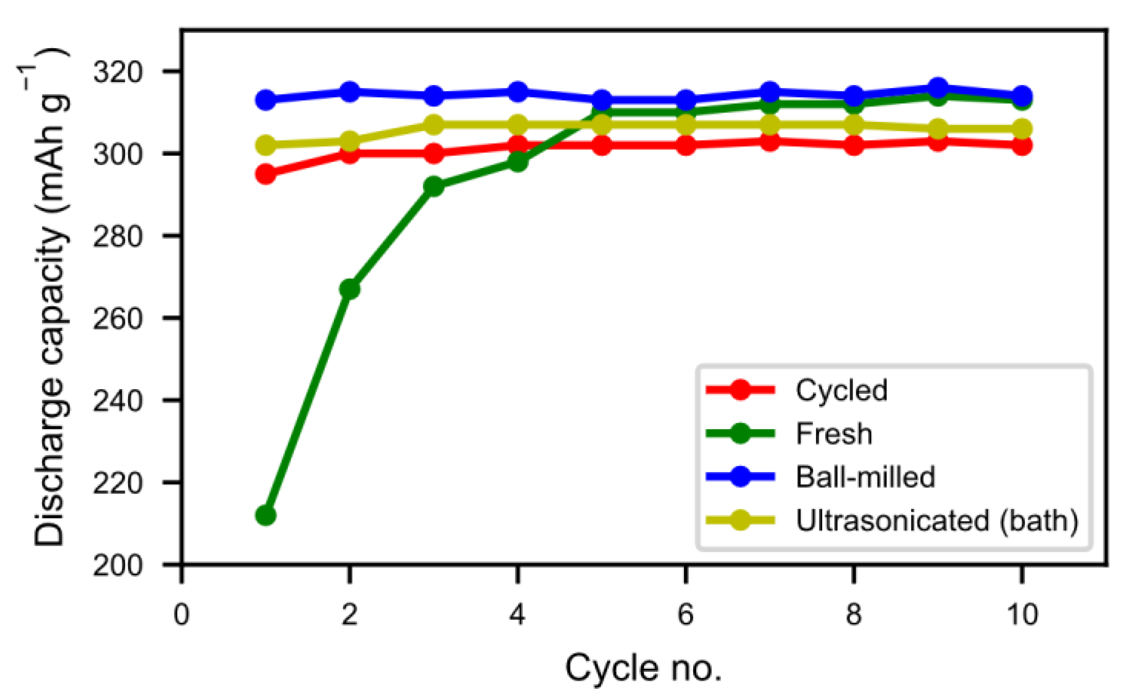
In
Figure 8 we can see that the half-cell measurement of the cycled alloy straight out of the spent battery lost about 5% of the initial capacity, showing that most of the alloy capacity remains even if the battery has passed the end-of-life criteria caused by electrolyte dry-out. The balled-milled and washed alloys showed the best performance. Not only did they reach the capacity of the pristine alloy but they also showed a very rapid activation. This indicates that the active surface created by the corrosion during the formation of the original battery alloy was still in most aspects intact. The ultrasonic bath-sonicated sample showed a similar behavior even if it did not reach the same capacity, probably due to a less effective removal of the rare-earth hydroxide corrosion products.
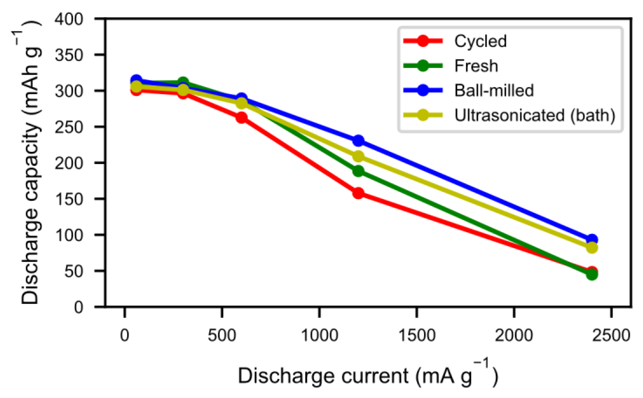
The tendency towards improved and quicker activation was also reflected in the high rate discharge properties (
Figure 9). As a result of the cycling during the previous long-term testing, the alloy particles formed not only an active surface but they also cracked up into smaller particles, thus increasing the surface area. As such, the reaction kinetics were not only improved by the presence of a reactive surface, but also by a more accessible surface. As seen in
Figure 6, however, a number of those particles did not separate properly, leading to long diffusion paths in the electrolyte. Sonication and ball-milling help to open up the agglomerated particles, resulting in better accessibility for the ionic transport.
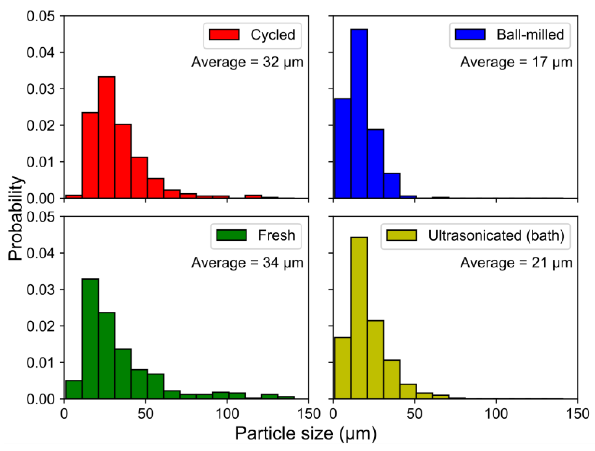
The fragmentation of the particles by ball-milling and sonication also changed the particle size distributions (
Figure 10), where the smaller particle sizes in the ball-milled and bath-sonicated materials corresponded to a larger active surface.
The same characterizations were performed on acid-treated samples.
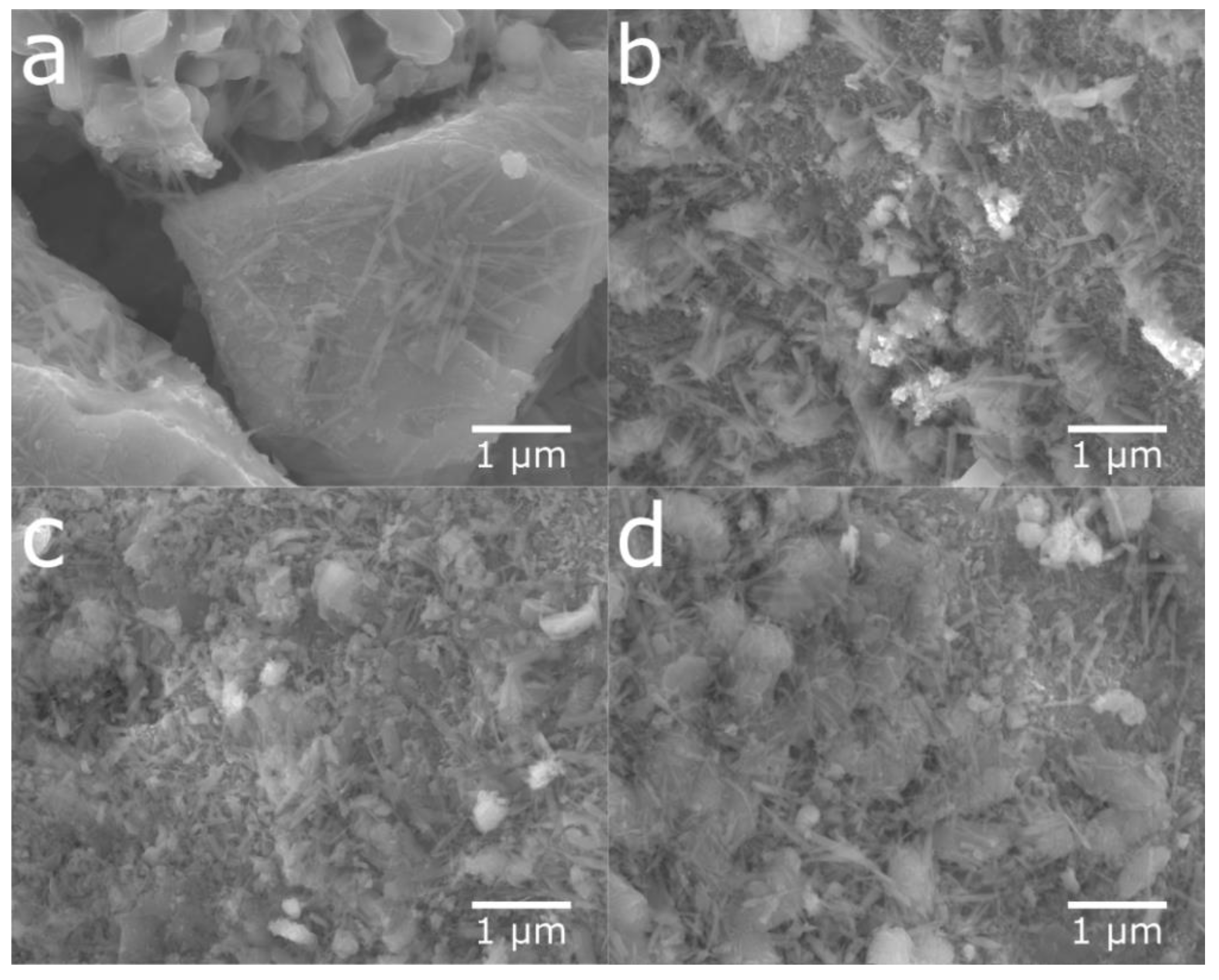
Figure 11 shows SEM micrographs of the cycled alloy before the acid treatment and of samples treated with different concentrations of sulfuric acid. The layer of needle-shaped crystals was completely removed when using H
2SO
4 solutions with concentrations of 0.05 M to 1 M (
Figure 11b–d). However, with high acid concentration, the bulk alloy was attacked (
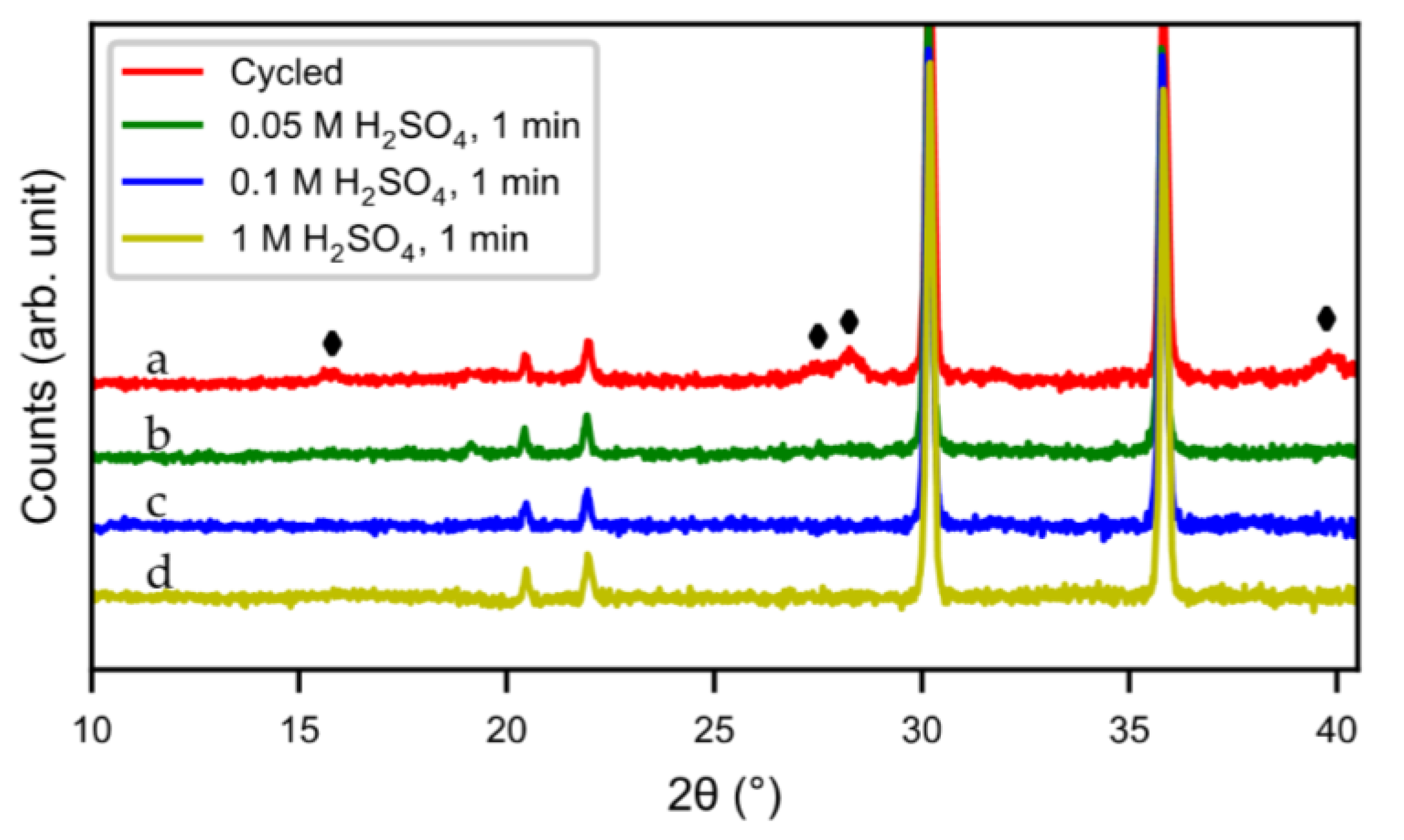
Figure 11d). The result was confirmed by XRD (
Figure 12). Compared to the original cycled alloy, the rare-earth hydroxide peaks of samples after acid treatments were non-existent. The discharge curves from half-cell tests (
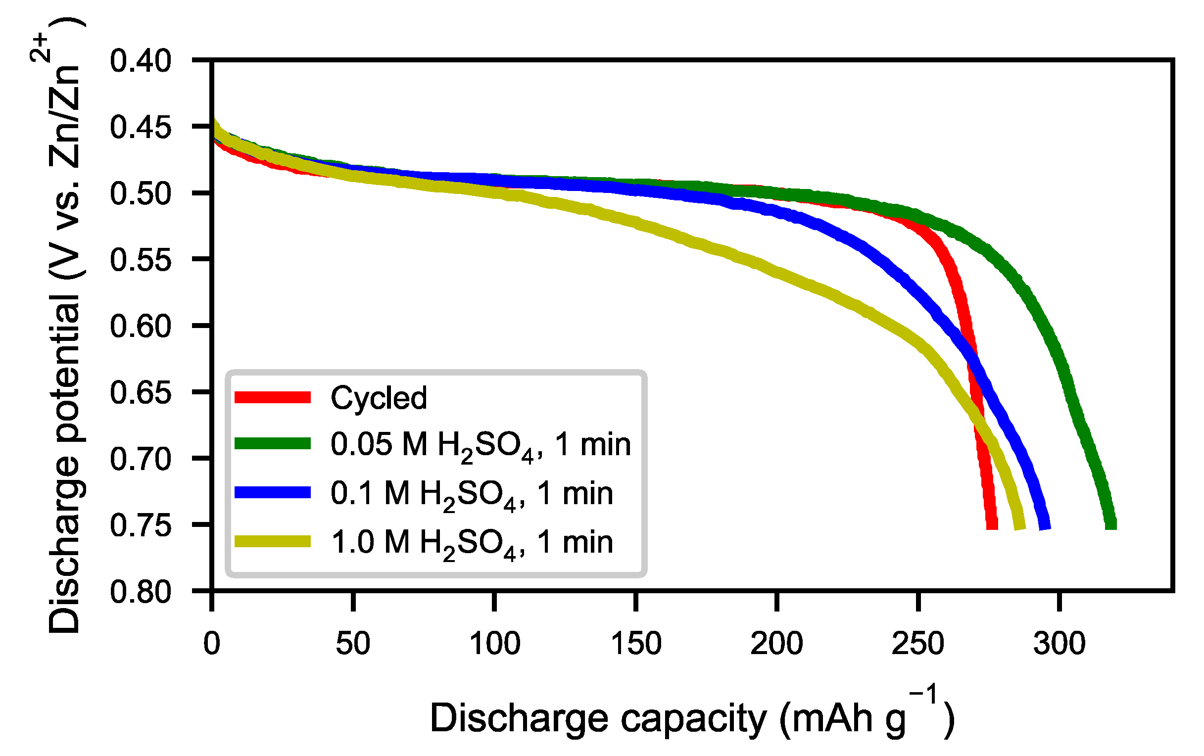
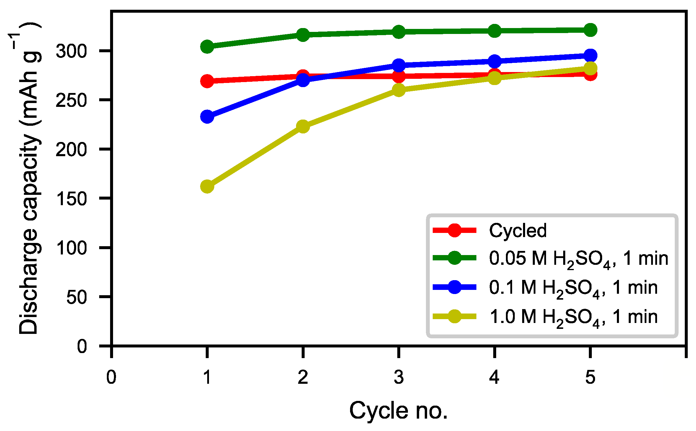
Figure 13) showed an optimum capacity for the sample treated with the lower concentration of H
2SO
4. The sample which was treated in 0.05 M H
2SO
4 for 1 min also showed a very rapid activation (
Figure 14). This indicates that the active surface created by the corrosion during the formation of the original battery alloy was still in most aspects intact (as we described for ball-milled sample above). Samples treated with higher concentration of H
2SO
4 (0.1 M and 1 M) showed slow activation, because the active surface/interphase was probably damaged. This indicates that the presence of an interphase was important for good performance, supplying both corrosion protection as well as catalytically active species. The results indicate that the RE hydroxide is very quickly dissolved with dilute sulfuric acid solutions, but also that it is difficult to design practical procedures to obtain optimal performance with a suitable thickness of the passive surface layer.
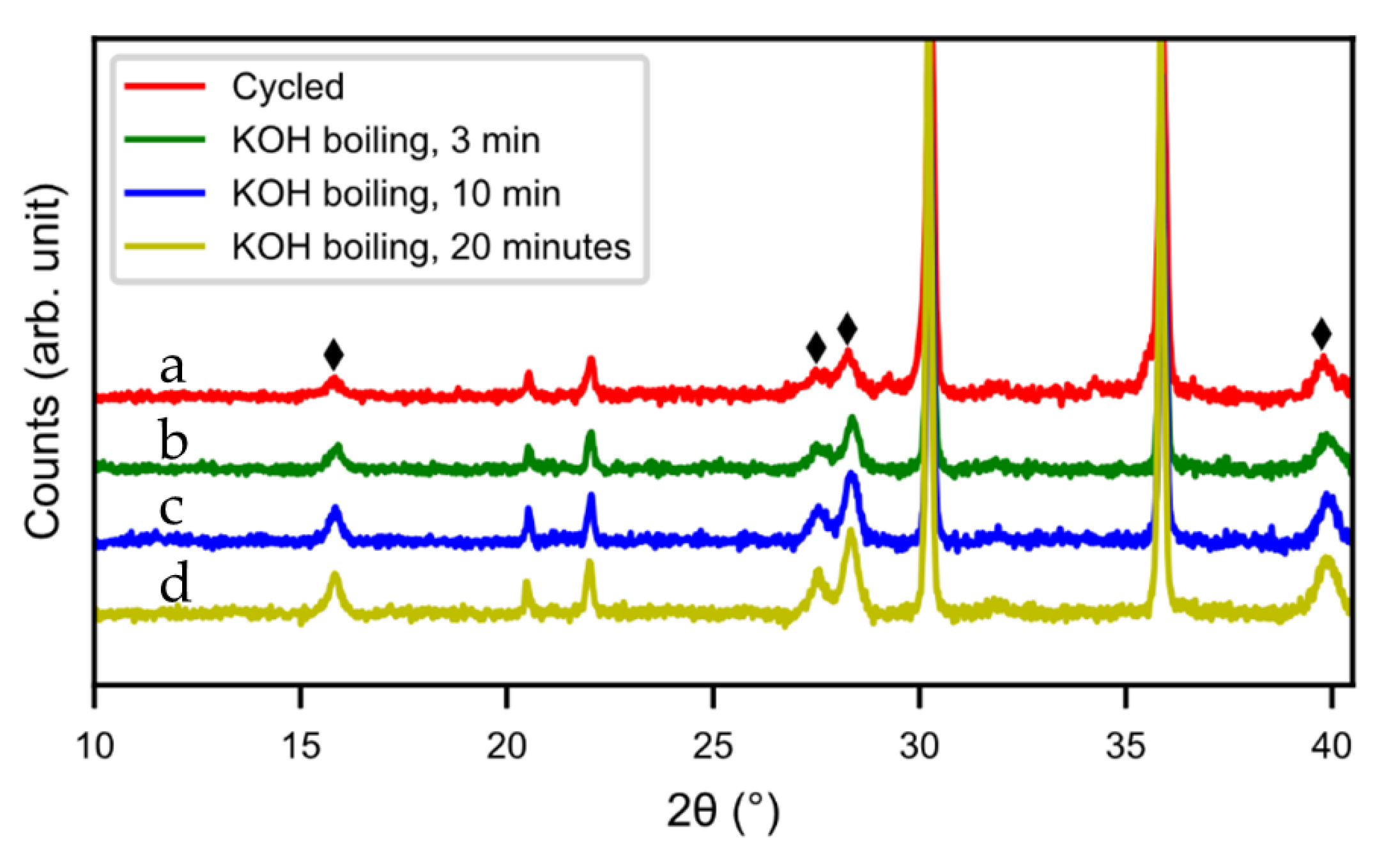
Hot KOH was also evaluated as a possible washing media. Three different washing times were tested (5 min, 10 min, and 20 min) but the hydroxide layer could not be removed. The layer grew even thicker in hot KOH, as can be seen from the SEM images (
Figure 15) and XRD pattern (
Figure 16). During the treatment, the alloy cracked into smaller particles and hydroxide layers formed on the new surfaces. Also, the size of the needle-shaped hydroxides increased in the KOH.
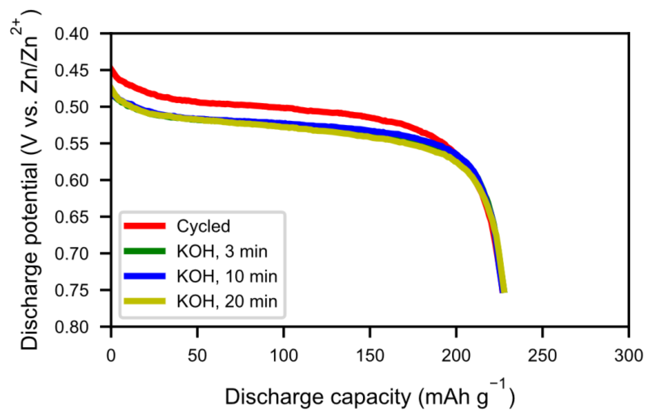
Figure 16 shows the discharge curves of alkaline-treated samples. There was not much change in capacity with 20 min of hot KOH boiling. In addition, the resistance increased, as seen by the lower voltage in
Figure 17, indicating a poorer contact resistance caused by the additional corrosion. Therefore, hot alkaline washing does not seem to be a good method to regenerate spent alloy.


