Article

Utilization of Greenhouse Gases for Syngas Production by Dry Reforming Process Using Reduced BaNiO3 Perovskite as a Catalyst

1
Department of Chemistry, College of Science, King Saud University, P.O. Box 2454, Riyadh 11451, Saudi Arabia
2
Department of Zoology, College of Science, King Saud University, P.O. Box 2454, Riyadh 11451, Saudi Arabia
3
Central Laboratory, Department of Botany and Microbiology, College of Science, King Saud University, P.O. Box 2454, Riyadh 11451, Saudi Arabia
4
Central Laboratory, College of Science, King Saud University, P.O. Box 2454, Riyadh 11451, Saudi Arabia
*
Author to whom correspondence should be addressed.
Sustainability 2021, 13(24), 13855; https://doi.org/10.3390/su132413855
Submission received: 27 October 2021 / Revised: 28 November 2021 / Accepted: 7 December 2021 / Published: 15 December 2021

Abstract

:
For the commercialization of syngas production, the utilization of greenhouse gases and the fabrication of an active catalyst for the dry reforming methane (DRM) process are the biggest challenges because of deactivation by carbon deposition, oxidation, sintering, and loss of active surface sites under high temperature. In the present article, BaNiO3 perovskite was synthesized by the coprecipitation method, and its reduced form (r-BNO) was utilized for syngas production by the DRM reaction. It was found that the r-BNO showed high stability and good resistance against carbon deposition, however, the conversions (CH4 and CO2) have been found to be less than 50%. Many techniques such as TGA, XRD, FT-IR, UV-Vis, BET, SEM, TEM, XPS, TPR, TPO, and TPD were used in order to investigate the physical properties and evaluation conditions for syngas production. From the obtained results, it was revealed that BaNiO3 perovskite possessed a hexagonal crystal structure and perforated–rough surface; in addition, its structure was virtually regenerated by oxidation of the r-BNO catalyst, which provides a convenient way to regenerate the original catalyst in an oxidative atmosphere. Structural and surface alterations of the used catalyst, after the DRM reaction, were characterized by using TGA, TPO, and TEM, and it was found that there was no significant deposition of inert carbons (D and G) and deactivation of the r-BNO catalyst.

1. Introduction

The production of clean energy from existing sources (renewable and nonrenewable) around us is one of the most comprehensive tasks for scientists and industrialists, aiming to establish an economically sustainable and a sensible technique which can consume these reserved raw materials and produce value-added products, such as liquid hydrocarbon fuels and oxygenated chemicals. One of the inevitable routes to utilizing natural gases such as liquid fuels as well as clean energy production is gas-to-liquid (GTL) technology, the pollutant technique with the lowest emission [1,2]. Towards this direction, synthesis gas, a mixture of H2 and CO, is a skilled and efficient approach to clean energy production in the form of liquid fuel. The implementation of syngas production is an attention-grabbing topic among researchers, since it is the junction point at which we can move from the hydrocarbon age to the hydrogen age [2,3,4].
In spite of various opened channels for syngas production, the reforming of methane with various oxidants is one of the most environmental friendly and convenient techniques because of its economic viability, technical sustainability, and it being easier to process than others [2,5,6]. Depending on the H2/CO ratio, it can be useful for the manufacturing of many chemicals of industrial interest at a large scale. For example, the exposure of CO and H2 to various CO/H2 ratios at high and low temperatures is employed to improve the preferential/selective oxidation of CO in the presence of hydrogen on supported Au catalysts, Au/TiO2, as reported by Hartadi et al. [7]. Well-reported in the literature is that the H2/CO ratio is close to one, producing many important liquid hydrocarbons (Fischer–Tropsch synthesis) and oxygenated chemicals; they are practically important intermediates for the processing of fuels and value-added products (formaldehyde, alkenes, oxygenates, polycarbonates, or methanol). In contrast, with a higher H2/CO ratio, for example, the steam reforming of methane (H2/CO > 3) favors methane formation and inhibits long-chain hydrocarbon formation [5,6,8,9]. The 1:1 ratio of H2/CO is, technically, processed by reforming the reaction of methane with a carbon dioxide oxidant, and this technique is well-known as the dry reforming of methane (DRM). Luckily, and as a bonus for this conversion process, both are greenhouse gases, which are responsible for global warming; moreover, this has been a well-known phenomenon for decades, which makes it easy to provide awareness about safety and the cleanness of the ecosystem to the community, which are applied and frequently used as a method for the various energetic vectors [2,5,8]. However, due to its endothermic nature, it suffers from the decomposition of methane and the disproportion of carbon monoxide as a result of coke formation, sintering, and deactivation of catalysts used in the DRM conversion process [10,11,12,13,14,15].
Many kinds of materials have been distinguished in the DRM reaction, such as carbides, sulfides, noble metals, and supported and unsupported oxides [10,11,12,13,14,15,16,17]. Luhui Wang et al. [18] reported that encapsulated Ni nanoparticles supported on SiO2 (Ni@La2O3)/SiO2), fabricated by the one-pot colloidal solution combustion method, is an excellent catalyst for the inhibition of carbon deposition during the DRM process at 700 °C, because only 1.6 wt % C was formed after 50 h reaction. In fact, Ni-based catalysts are an economically cheap source, and possess the capability of excellent catalytic activity and selectivity equally; noble metals for syngas production, by contrast, are quickly deactivated during the course of the reaction for the aforesaid reasons, for example, coke deposition/sintering [19,20,21]. In spite of their deactivation, researchers are continuously trying to improve the features of Ni-based catalysts with the dispersion of nanosized particles using various procedures, such as the synthesis process, addition of promotors, and modification of basicity, etc., to create resistance of the deactivation parameters [10,12,13,14,19,21].
Recently, in situ-generated supported materials are a more sophisticated method for the DRM reaction. Well-defined structural perovskite (ABO3) precursors are an important source for the generation of such kinds of materials, which can easily produce supported oxides, such as B/AOx [8,9,22,23,24], in a reduction medium. Therefore, perovskite oxide can be considered an important precursor of metal catalysts, or as a catalyst that should be either activated or performed on the reactor catalytic bed by the reduction process. In particular, an attractive option for the DRM using perovskite structures provides all the requirements, such as high thermal stability and well-dispersed supported oxide, however, it faces the issue of a low surface area in a defined structure. Briefly, perovskites have a general formula, ABO3, in which the A ions can be rare-earth, alkaline earth, or alkali elements that fit into dodecahedral sites of the framework, while the B ions can be 3D, 4D, and 5D transition metal ions, which occupy the octahedral sites, whose vertices are occupied by O2−. It has a unique structural capability for accepting a wide range of substitutions. These solids are very resistant to high temperature, and they are mechanically and chemically stable under typical reaction conditions. In this respect, many efforts have been carried out to synthesize Ni catalysts that are resistant to carbon deposition, by introducing metal in the defined perovskite oxides [8,9,22,23,24]. Dupeyrat et al. [23], following the concept of Shiozaki et al. [22], synthesized the LaNiO3 perovskite by pulse technique and utilized it for the DRM reaction, and found 98% CH4 and 88% CO2 conversions without coke formation after the reduction at 700 °C. Hayakawa et al. used CaTi1−xNixO3 as a catalyst precursor for the partial oxidation of methane to syngas [20]. Verykios and coworkers [19,25,26] proposed a new type of synergetic active sites created at the Ni–La2O3 interface by the interaction between nickel and lanthanum species, which offer active and stable performance syngas production DRM process. Slagtern and Olsbye [27] reported high activity of the reduced B metal for methane conversion into syngas on LaBO3 (B = Rh, Ni, Co) perovskites.
According to promising features of perovskites, we synthesized BaNiO3 by the coprecipitation method, and its reduced form was used for synthesis gas production by the DRM. The crystalline, optical, morphological, and surface properties are examined by various techniques such as XRD, SEM, TEM, BET, TG-DTG, UV-DRS, and XPS. XRD and TPR results were used to characterize the reduced perovskite catalyst. Furthermore, the physical–chemical modifications during the catalytic performance were investigated with TPO, TEM and TG-DTG techniques.

2. Materials and Methods

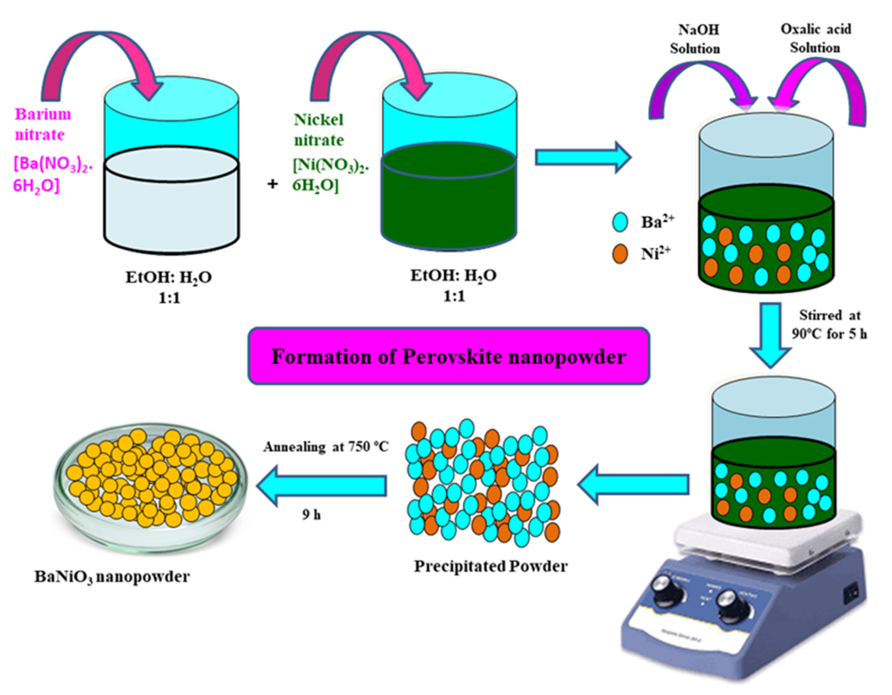
2.1. Preparation of Perovskite BaNiO3

Perovskite BaNiO3 was prepared by the coprecipitation method using a mixture of ethanol and water (1:1) as a solvent. The reactants used for the preparation of BaNiO3 were nitrates of barium [Ba(NO3)2.6H2O], nickel [Ni(NO3)2.6H2O], oxalic acid and sodium hydroxide. All the starting materials were of analytical grade (purity > 99%). Briefly, metal nitrates (1:1) were separately dissolved in a hot mixture of ethanol and water until the formation of transparent solution. After dissolution the solution of Ba and Ni was mixed and 0.5 g oxalic acid added to the mixture. After stirring for 30 min, 1 M NaOH (pH > 8) was added and again stirred at 90 °C for 5 h. The obtained greenish precipitate was filtered and rinsed with water, ethanol, and acetone; it was kept in hot oven for 24 h at 250 °C. Moreover, the obtained dry product was air calcined at 750 °C for 9 h to obtained the desired perovskite product. The schematic representation of synthesis is shown in Scheme 1.

2.2. Characterizations

X-ray diffraction (XRD) patterns of fresh and reduced samples were performed on X-ray diffractometer (Rigaku D/Max-III C, Tokyo, Japan) with CuKα radiation (λ = 1.5406 Å), and operated at 40 kV and 100 mA in continuous mode at the rate of 0.3°/min from 10° to 80° scan range. Thermogravimetric analysis (TG-DTG) was performed using TGA instrument (STA Jupiter 449 F3 equipment, Selb, Germany) at a heating rate of 10 °C/min from room temperature to 900 °C under the synthetic air flow. TGA analysis was used to find out calcination temperature for the formation of perovskite structure and the amount of deposited carbon on the catalyst after the reactivity tests. The Fourier-Transform Infrared Spectroscopy (FT-IR) examinations were performed by KBr pellet method in the 400–4000 cm−1 scan range on Bruker Vertex 70, Germany. Band-gap energy was measured on double beam spectrophotometer (Jasco UV-Vis 770, Tokyo, Japan) in the wavelength range of 200–800 nm at room temperature. The morphology was studied by scanning electron microscopy (SEM) on a TESCAN-FERA3 microscope (Fuveau, France) using an accelerating voltage of 15 kV. Transmission electron microscopy (TEM) of fresh and used catalyst was performed with JEOL JEM-1011 microscope (Tokyo, Japan) operated at 80 kV. The X-ray photoelectron spectroscopy (XPS) was used to measure chemical states and surface element composition with a monochromatic AlKα radiation source and charge neutralizer by Scienta Omicron, Uppsala, Sweden. The C 1s line was taken as an internal standard at 284.6 eV. Both wide-range survey and detailed spectra (for Ba, Ni and O) were collected at 300 W. BET specific surface area and BJH pore size distribution were determined by adsorption of N2 at −196 °C using a Micromeritics Tristar II 3020 surface area and porosity analyzer instrument (Norcross, GA, USA). Prior to analysis, the sample was degassed for 2 h at 250 °C. Temperature Programmed Reduction, oxidation, desorption, and amount of deposited carbon on the catalyst after the reactivity tests were performed with a Micromeritics Auto Chem II 2920 analyzer equipped with a TCD detector (Norcross, USA). For the H2-TPR experiment, approximately 75 mg of the calcined catalyst was placed in a U-shaped quartz tube (6.6 mm ID) and subjected to heat treatment with Ar flow for 60 min at 250 °C, in order to remove water. Then, the reducing gas, consisting of 10% H2 in Ar, was introduced at a flow rate of 30 mL/min, with a heating ramp rate of 10 °C/min from room temperature to 800 °C, which was maintained for 60 min. After the reduction, the sample was cooled down to room temperature and purged with helium. After this treatment, O2-TPO experiment was performed in the presence of 10% O2 in He gas mixture at the rate of TPR conditions. Similarly, CO2-TPD was also performed on the same instrument and similar condition to TPR except for differences in the mixture gas (10% CO2 in He).

2.3. Catalytic Activity Measurements

Dry reforming of methane (DRM) reaction was carried out at atmospheric pressure in a 9.4 mm i.d. and 48 cm-long stainless steel PID Microactivity reactor (Micromeritics, Norcross, GA, USA) using 0.6 g of the catalyst. The reaction temperature was measured using a K-type thermocouple placed in an axial thermowell centered in the catalyst bed. For the DRM experiment, the sample was first activated by H2 flow at the rate 30 mL/min at 700 °C for 2 h followed by N2 flow (30 mL/min) for 30 min. The total flow rate and volume ratio of the feed gases (CH4:CO2:N2) were 36 mL/min and 17:17:2, respectively. The reforming activity was studied at 700 °C while the effluent gases were analyzed by an online Varian Star CX3400 gas chromatography (Santa Clara, CA, USA) equipped with a thermal conductivity detector and columns packed with Porapak N and 13X Molecular sieves (Varian, Santa Clara, CA, USA). The reported results of catalytic activity tests present an average of triplicate runs. These runs were performed with good reproducibility, and the conversions of methane and carbon dioxide were reproducible within an error of ±2%. Conversions (CH4, CO2), selectivity (H2, CO), yields (H2, CO) and H2/CO ratio are calculated by the following formulae:
CH 4   conversion   ( % ) = ( mole   CH 4 , in moleCH 4 , out mole   CH 4 , in ) × 100
CO 2   conversion   ( % ) = ( mole   CO 2 , in moleCO 2 , out mole   CO 2 , in ) × 100
H 2   yield   ( % ) = ( mole   H 2 , out 2 × mole   CH 4 , in ) × 100
CO   Yield   ( % ) = ( mole   CO out mole   of   CH 4 , in +   mole   CO 2 , in ) × 100
Ratio   of   H 2 / CO   = ( mole   H 2 , out mole   CO 2 , out )

3. Results and Discussion

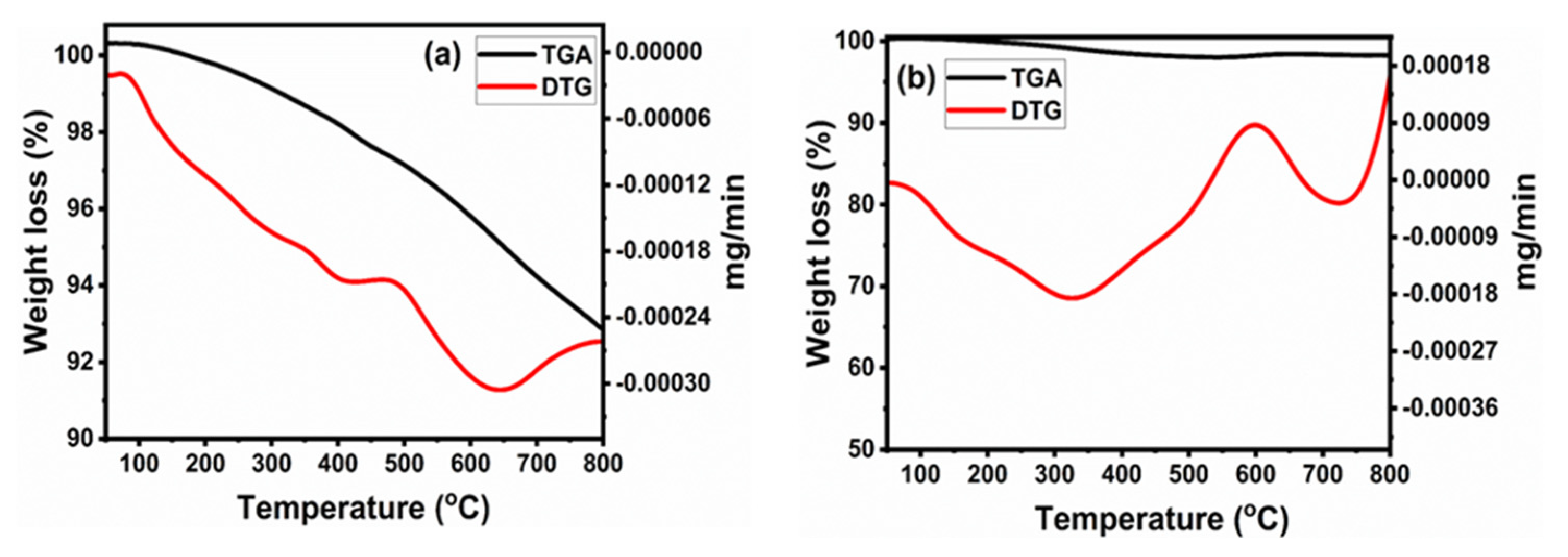
3.1. Thermal Analysis (TG-DTG)

Figure 1 shows the TG-DTG graph ranging from room temperature to 900 °C for the decomposition of the oven-dried perovskite precursor and spent catalyst in the synthetic air medium. The decomposition process for the oven-dried perovskite precursor can be distinguished into two steps (Figure 1a). In the first step, about 6% weight loss from room temperature to 415.8 °C is due to desorption of surface water, decomposition/oxidation of free oxalate into CO2 gas, and H2O vapor. Likewise, in the second step, about 3% weight loss at temperature 646.8 °C reflects the initiation of the Ba–Ni–oxalate bond decomposition, gasification of nitrates into NOx, and crystallization of perovskite from amorphous precursor. Therefore, the total weight loss up to 800 °C is around 9%. Having been observed, the final product was calcined at 750 °C for 9 h, which provided strong evidence of the formation BaNiO3 perovskite. Furthermore, these observations are comparable to the results obtained from the XRD pattern of the calcined sample (Figure 2a), which confirms the transformation of amorphous to hexagonal perovskite phase.
The amount of carbon deposition over the used catalyst after a 5 h stability test at 700 °C in the DRM process was determined by thermogravimetric analysis, which is presented in Figure 1b. TGA curve clearly showed that the spent catalyst has very good resistance to coke formation (0.05% coke deposition). The contribution of carbon deposition by the metal oxidation is negligible during thermal oxidation of the spent catalyst. Therefore, the observed DTG peaks of the spent sample can be the gasification of deposited reactive carbons on the catalyst surface. Two types of carbons were observed by DTG: one at 330 °C and second at 730 °C. The low-temperature DTG major peak suggests the formation of reactive amorphous carbon, whereas the high-temperature DTG minor peak supports the formation of filamentous carbon. One minor peak around 125 °C can be attributed to loss of moisture, which confirmed that the reverse water–gas shift reaction (RWGS) reaction occurred during DRM process. It is reported in the literature that the formation of reactive carbon does not favor catalyst deactivation, while formation of inert carbon has an ultimate deactivation effect [28,29,30]. Thus, on the basis of the TG-DTG results, it can be concluded that despite the formation of coke over the catalyst, its activity did not decrease, since the deposited carbon was reactive and there was no significant effect of metal size and its interaction with support.

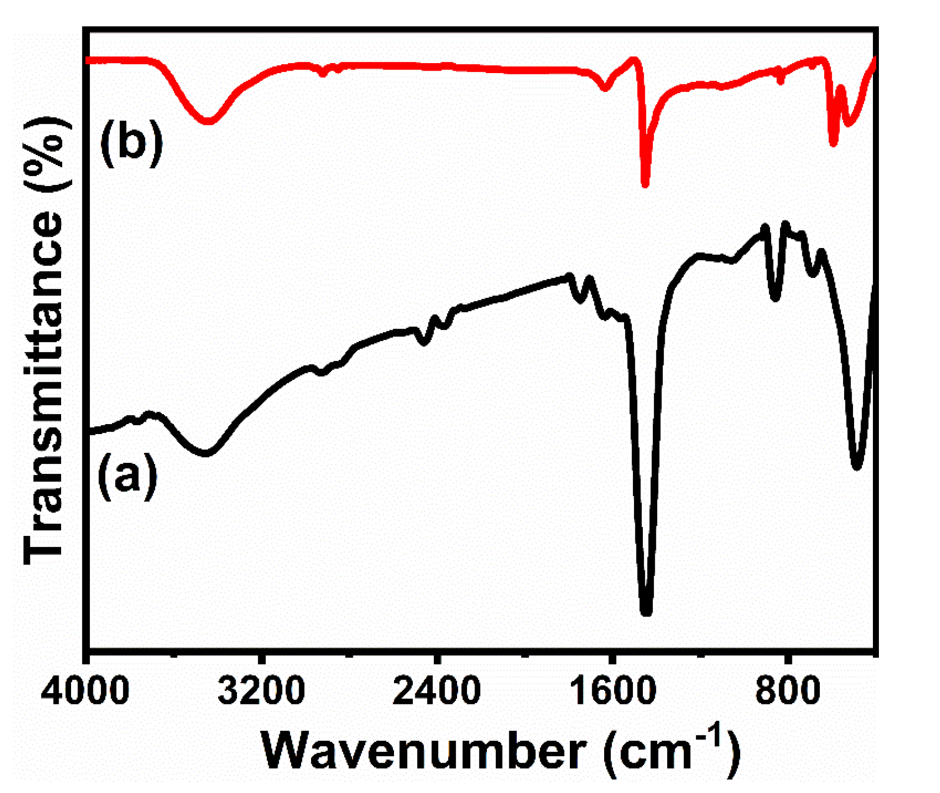
3.2. Fourier-Transform Infrared Spectroscopy Analysis (FT-IR)

Figure 2 represents the FTIR spectra of the perovskite precursory and the calcined perovskite. In the spectrum of perovskite precursory (curve a), the broad, strong absorption peak at 3453.38 cm−1 is assigned to the combination of H–O bending mode of absorbed water and the hydroxyl group [31,32]. The weak band at 2915.16 cm−1 is due to aliphatic C–H stretching from the oxalic acid. The bands at 2353.74 cm−1 and 1764 cm−1 are attributed to the symmetric and asymmetric stretching of the carboxylate group, respectively. The bands recorded at 1427.84 cm−1, 1062.17 cm−1, and 855.84 cm−1 correspond to the principal vibration of the (CO3)2- group, indicating that Ba-carbonate species exist [33]. Furthermore, the absorption band at 690.30 cm−1 is assigned to specific vibrations of Ni–O bond [34]. After the calcination at 750 °C, intensity of the absorption bands of organic and inorganic, such as oxalate and carbonate, ions decreased, indicating the decomposition of these groups and formation of BaNiO3 perovskite (curve b). However, small amounts of (CO3)2− and hydroxyl groups were even seen in the calcined BaNiO3 sample. In addition, in the calcine sample, the Ni–O bond shifted to a lower frequency of 490.36 cm−1, ascribed the vibration of octahedral NiO6 group [35]. So, by the FT-IR results, it is very clear that no organic species or impurities are available at the surface of BaNiO3 during the synthesis, one of the excellent features of resistance of carbon deposition during syngas production.

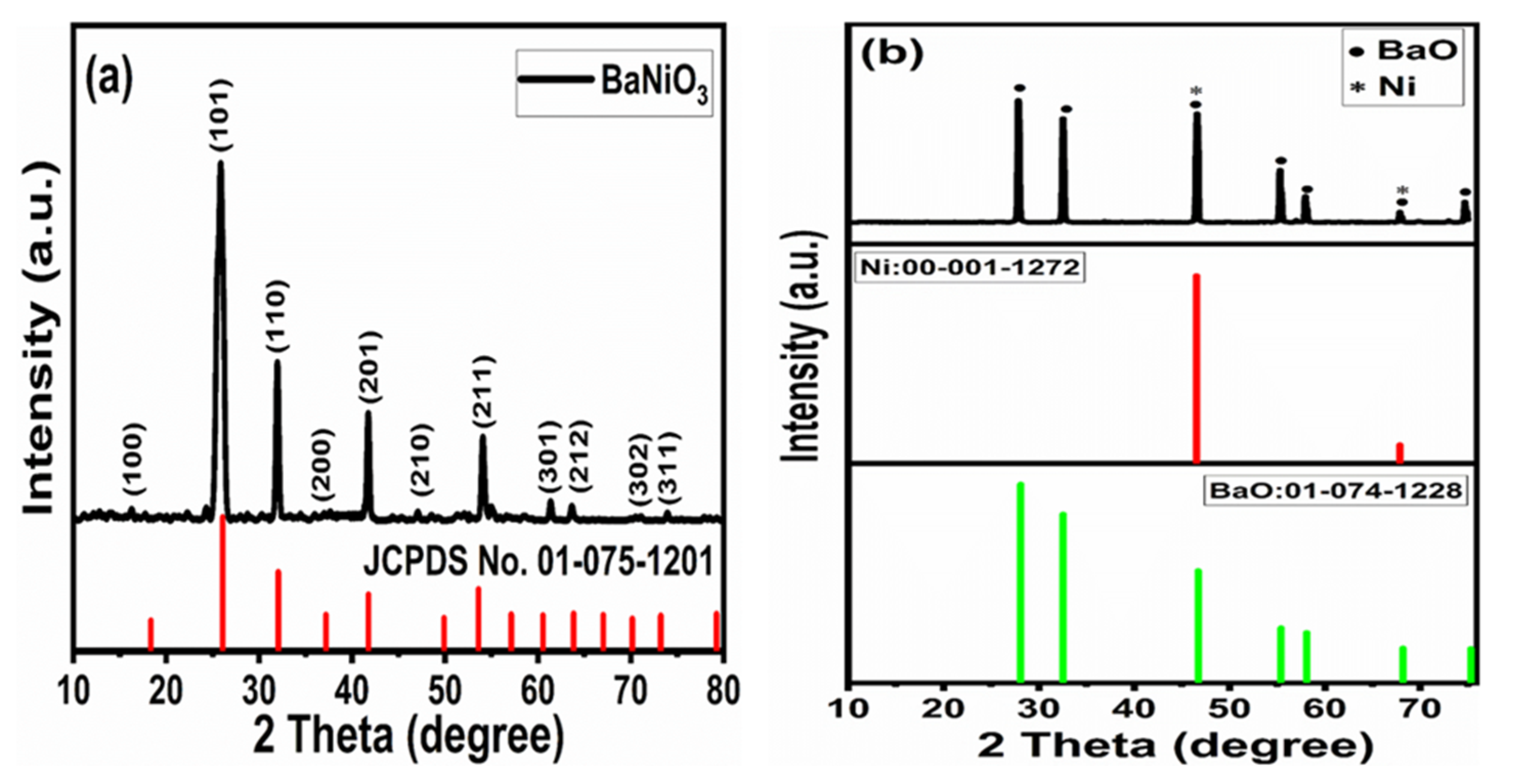
3.3. X-ray Diffraction Analysis (XRD)

XRD patterns for the calcined and reduced samples are shown in Figure 3. The XRD patterns of the calcined sample (Figure 3a) revealed that the conditions applied during calcination are good enough to produce the perovskite structure as the main phase, because no impurity phases such as BaO and NiO/Ni were detected. The perovskite structure was identified as a single phase with lattice parameter a = 5.58 Å, b = 5.58 Å and c = 4.83 Å and a hexagonal crystal system with P63mc space group (JCPDS no. 01-075-1201).
The diffraction patterns of r-BNO (Figure 3b), used as a catalyst for the DRM reaction, indicate that hexagonal BaNiO3 phase was not maintained after the reduction treatment. It is transformed into two phases: metallic Ni° species and BaO nanoparticles. It is observed that in reducing medium, Ni3+ cations reduce to metallic Ni° and exhibit the cubic crystal system with Fm3m space group (JCPDS no. 00-001-1272). The characteristic diffraction peaks at around 46.53° and 67.86° correspond to (100) and (200) crystal planes, respectively. BaO shows diffraction peaks at around 28.09°, 32.58°, 55.40°, 58.09° and 75.31° that are indexed to (111), (200), (311), (222) and (331) crystal planes, respectively, and exhibits the cubic crystal system with F23 space group (JCPDS no. 00-074-1228). These reflection patterns express the subsequent formation of BaO-supported Ni° crystallites. By applying the Scherrer equation to the most intense diffraction peaks in the XRD patterns [36], the average crystallite size values of the calcined and reduced samples were calculated, and found to be 22.12 nm for the calcined and 4.51 nm for reduced samples, respectively, indicating that no sintering of metal nanoparticles occurred during H2 reduction.

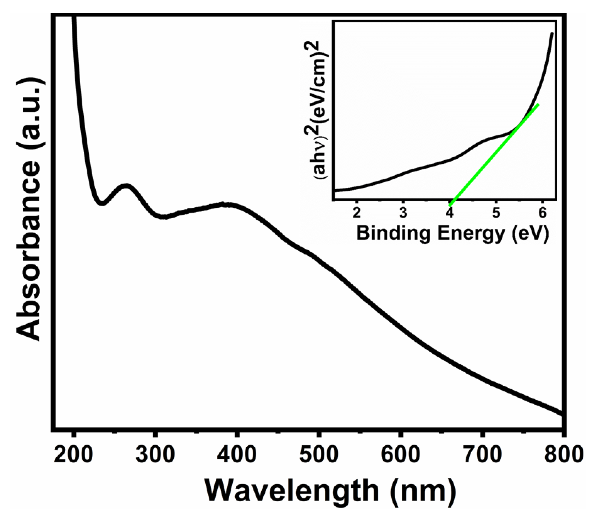
3.4. UV–Vis Spectroscopic Study

The optical absorption spectrum along with binding energy of cubic BaNiO3 nanostructure are depicted in Figure 4. The spectrum has two characteristic absorption regions. The first one is between 200–300 nm centered at 263.3 nm, and other one is in the range between 300–500 nm centered at 389.8 nm. These two regions correspond to the metal–metal transitions and crystal field transitions, respectively [37,38]. The optical band gap was calculated using the Tauc formula; the fundamental relationship between absorbance and incident photon energy () given by Equation (6),
( α h ν ) m = A ( h ν E g )
where, ‘α’ is the absorption coefficient, ‘’ is the photon energy, ‘A’ is a constant, ‘Eg’ is the band-gap energy, and ‘m’ equals 1/2 for a direct transition [39]. The inset of Figure 4 shows the plot of (αhν)2 vs. (), and the band-gap energy was determined by extrapolating the straight-line portion to the abscissa at zero absorption coefficient and found to be 4.11 eV.

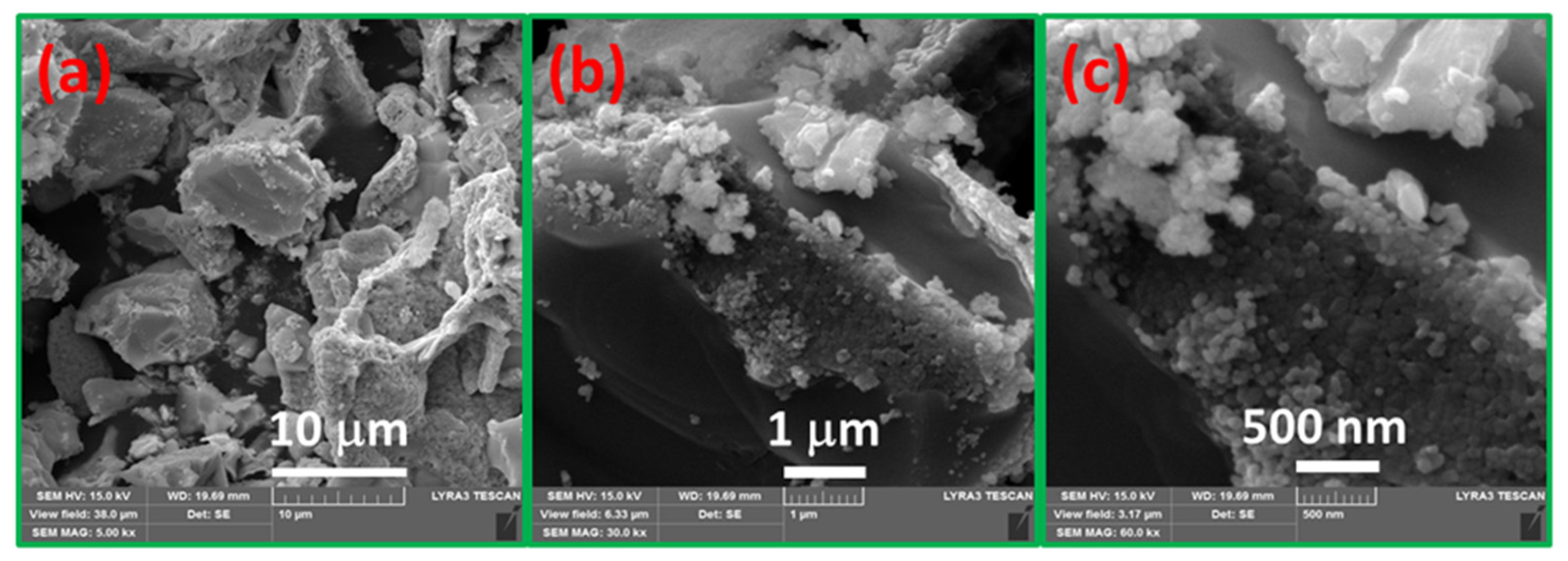
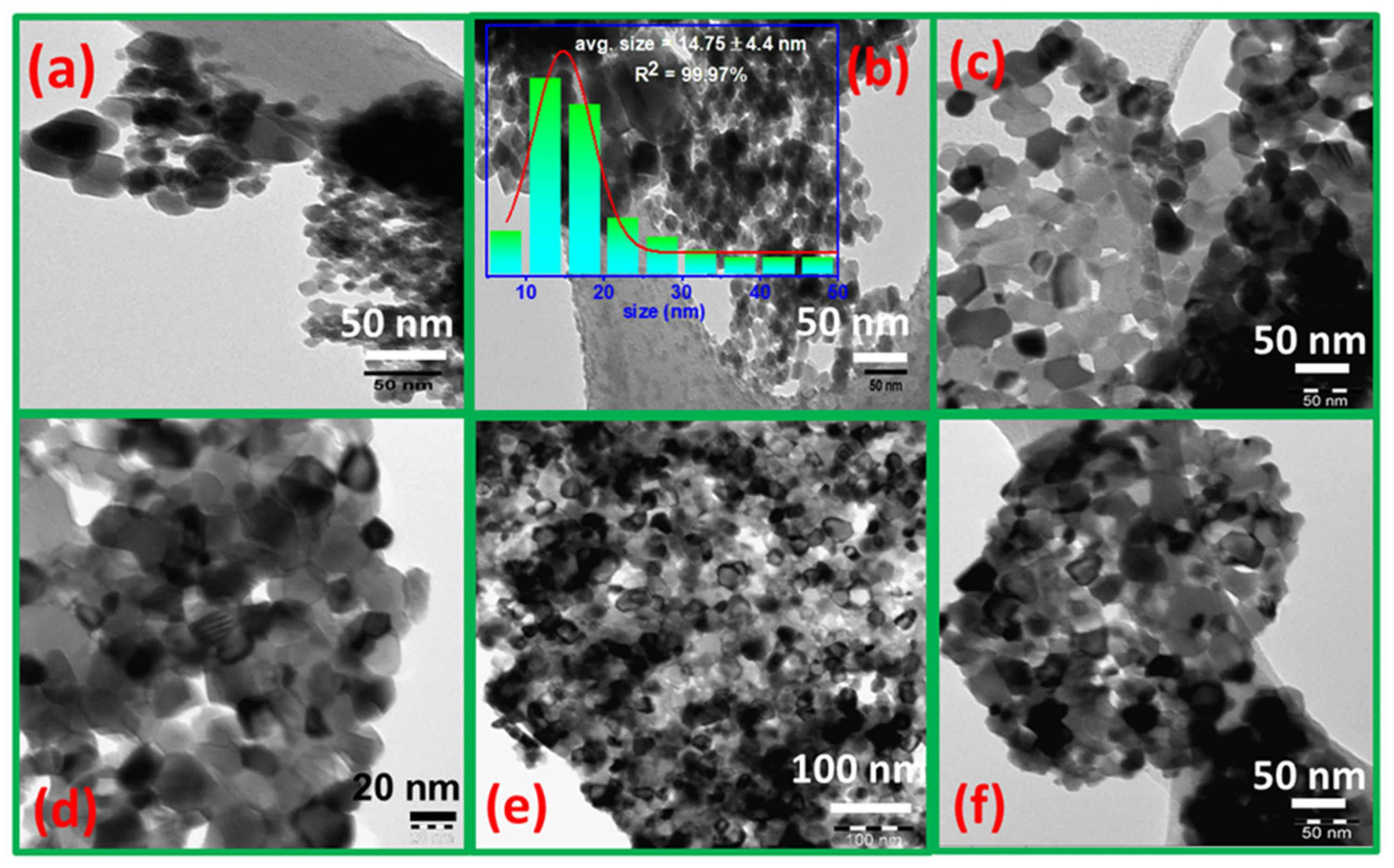
3.5. Morphological Analysis

Figure 5 shows the SEM images of the calcined sample at different magnifications. From the low-magnification SEM images (Figure 5a,b), it is certainly evident that BaNiO3 nanoparticles have a perforated and roughed surface, which could be attributed to the combustion of oxalic acid from its surface during calcination and crystallization processes. The highly magnified image (Figure 5c) shows that nanoparticles seem to be spherical along with large number of nanoparticles being interconnected. The interconnected nanoparticles look like a chain of spherical particles, with diameters ranging from 11.9 to 62.3 nm. Moreover, it was clearly noticeable that there are plenty of voids that are required features for the reduction and the DRM processes.
TEM pictures of fresh, reduced, and spent samples are presented in Figure 6. Typical TEM images of fresh perovskite and its particle size distribution (inset) are displayed in Figure 6a,b. It can be seen that the fresh BaNiO3 nanoparticles are in the form of pseudo-spherical-like and hexagonal-like, and these are well dispersed between 10 and 25 nm, which is matched with XRD data. In addition, similar to the SEM results, interconnected nanoparticles were well-observed in fresh perovskite.
After reduction, activated perovskite catalyst precursor (r-BNO) clearly shows (Figure 6c,d) a different morphology compared with fresh perovskite, presenting a smaller and uniform distribution of cubic Ni nanoparticles over the cubic BaO nanosupport. It is observed that Ni nanoparticles in r-BNO were partially embedded in the support as shown by the fringes (Figure 6d), and gradually come out from the support during the reduction process. The Ni° crystallites are the darker particles while the support particles are the lighter ones.
TEM images of spent catalyst (Figure 6e,f) clearly illustrate the aggregates of nanoparticles. After a long-term stability test, particle size and shapes became bigger and were destroyed, indicating that sintering occurred to some extent. However, some amount of amorphous carbon was observed in the spent catalyst. It is difficult to evaluate the size of a particular particle from the TEM picture, only the diameters of the aggregates of nonuniform spherical shaped structures, ranging from about 60 nm to 100 nm, can be derived.

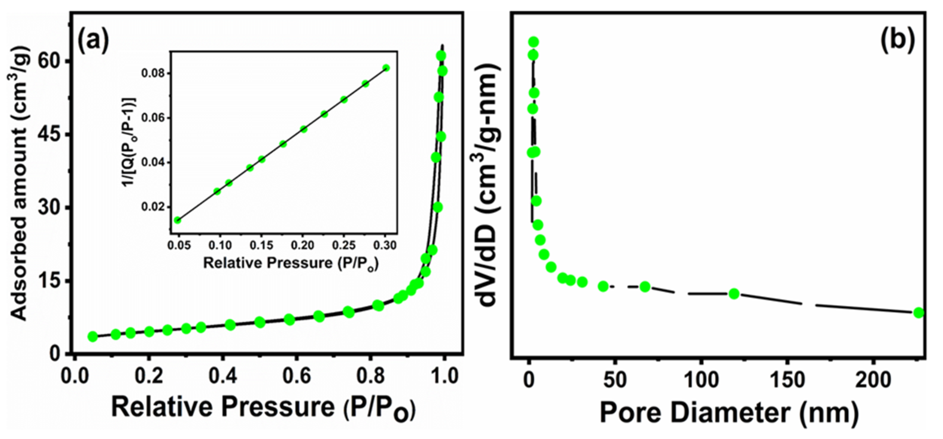
3.6. Textural Analysis (BET Surface Area)

N2 physical adsorption–desorption studies were conducted to determine the surface area and the pore structure of the synthesized BaNiO3 perovskite. The BET isotherm and BJH pore size distribution obtained from the desorption branch of the isotherm are shown in Figure 7. From Figure 7a, it is observed that the perovskite sample demonstrates type IV isotherm and H3 kind of hysteresis loop (0.8 < P/P0 < 1) due to capillary condensation, suggesting that it has a mesoporous surface, possessing pore volume 0.078 cm3g−1 and pore size 23.52 nm [40]. The BET specific surface area was found to be 16.18 m2g−1; inset of Figure 7a exhibits the adsorption data in relative pressure (P/P0) range 0.05–0.3. The pore size distribution (Figure 7b) showed a narrow peak centered at 2.8 nm.
In comparison to the fresh catalyst, the spent catalyst shows 2.65 m2g−1, 0.017 cm3g−1 and 24.75 nm surface area, pore volume and pore size, respectively, after 5 h of reaction. It is reported that carbon deposition, active metal sintering, and phase transformation are the main causes that can affect the textural properties of the catalyst under typical DRM reaction conditions [41]. In our case, the formation of carbon deposits over the spent catalysts was insignificant, as observed from TGA analysis (Figure 1b); therefore, the changes in textural properties can be attributed to sintering and aggregation of nanoparticles.

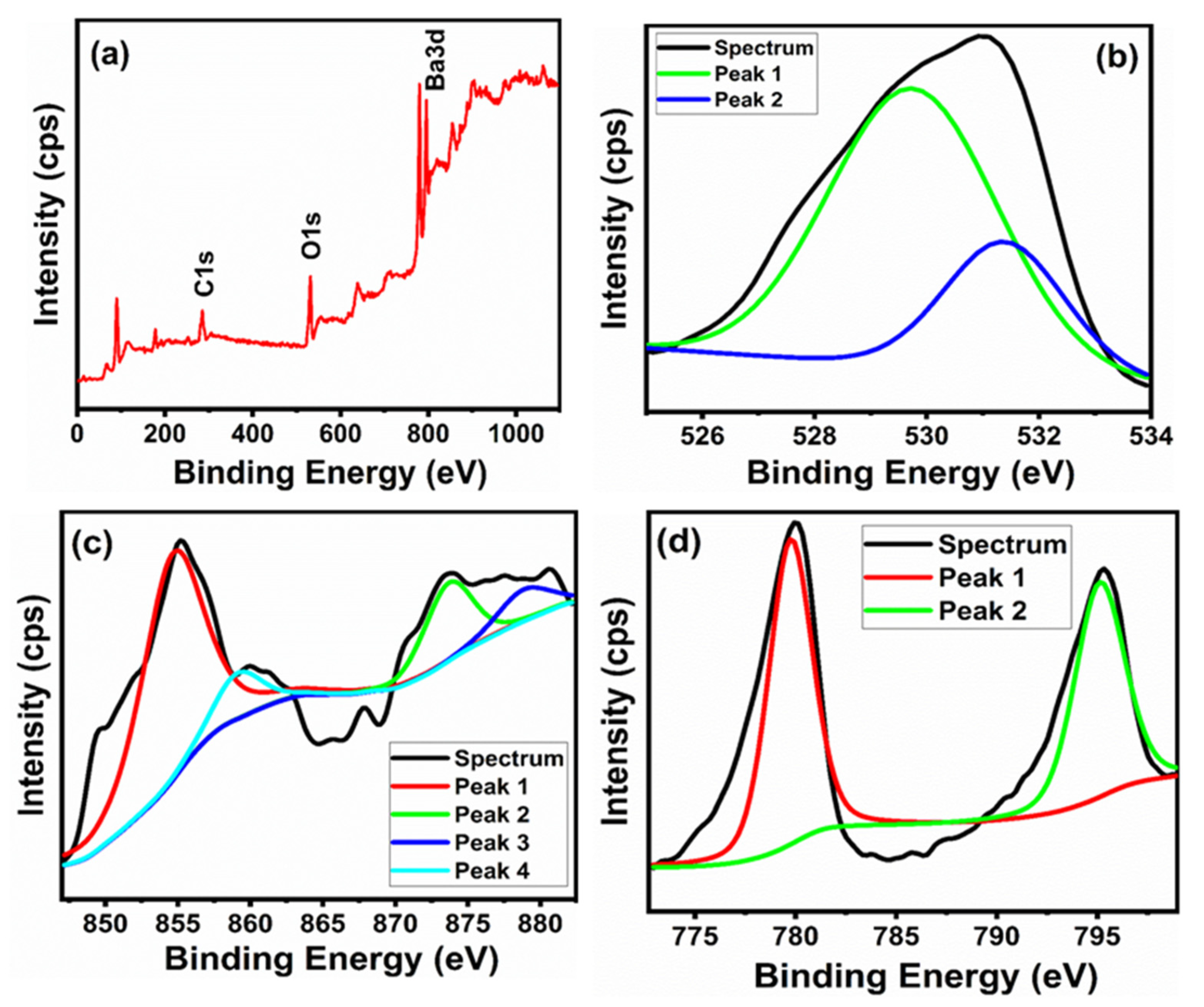
3.7. X-ray Photoelectron Spectroscopy (XPS)

The surface chemistry has an important effect on the catalytic activity because of the surface defect and composition. In order to acquire deeper information regarding the electronic and chemical properties at the surface of the fabricated sample, XPS studies have been performed. With this aim, the survey and narrow spectra of O 1s, Ni 2p, and Ba 3D of fabricated perovskite are collected and analyzed (Figure 8). The survey scan shows that there are four elements (Ba, Ni, O, and C) existing on the surface of the sample. The peak for C 1s at binding energy of 284.8 eV indicates the adventitious carbon from XPS instrument (Figure 8a). The O 1s profile shows two components after deconvolution of peaks (Figure 8b). These peaks appeared at: (a) 529.75 eV and (b) 531.36 eV. Type (a) peak is usually ascribed to lattice oxygen (O2−, Ni–O), whereas type (b) peak may arise from surface-adsorbed species such as hydroxyl (Ni–OH) and adsorbed molecular water, which have been considered to be related to the surface oxygen vacancies on the surface of the sample [42,43]. According to area of the peak, the ratio of surface lattice oxygen Olattice and adsorbed oxygen Oadsorbed was estimated to find out the amount of surface oxygen vacancies. It is noted that an Olattice/Oadsorbed ratio of 2.82, such oxygen vacancies would greatly promote the catalytic activity [44]. By a peak-fitting procedure, two pair of spin-orbit components were found in Ni 2p (Figure 8c). Due to the close similarity of BE of Ni2+ and Ni3+, it is difficult to discriminate between both species by XPS spectra alone. The two peaks located at about 854.64 and 873.67 eV are ascribed to Ni 3p, whereas two fitted peaks at about 859.15 and 878.86 eV are assigned to Ni 2p [35,45,46]. Figure 8d exhibits the Ba 3D core-level spectrum and there are two well-separated pairs of spin-orbit components at 795.12 eV and 779.75 eV, respectively. These binding energies are ascribed to barium bound in the lattice of hexagonal BaNiO3 nanoparticles [47].

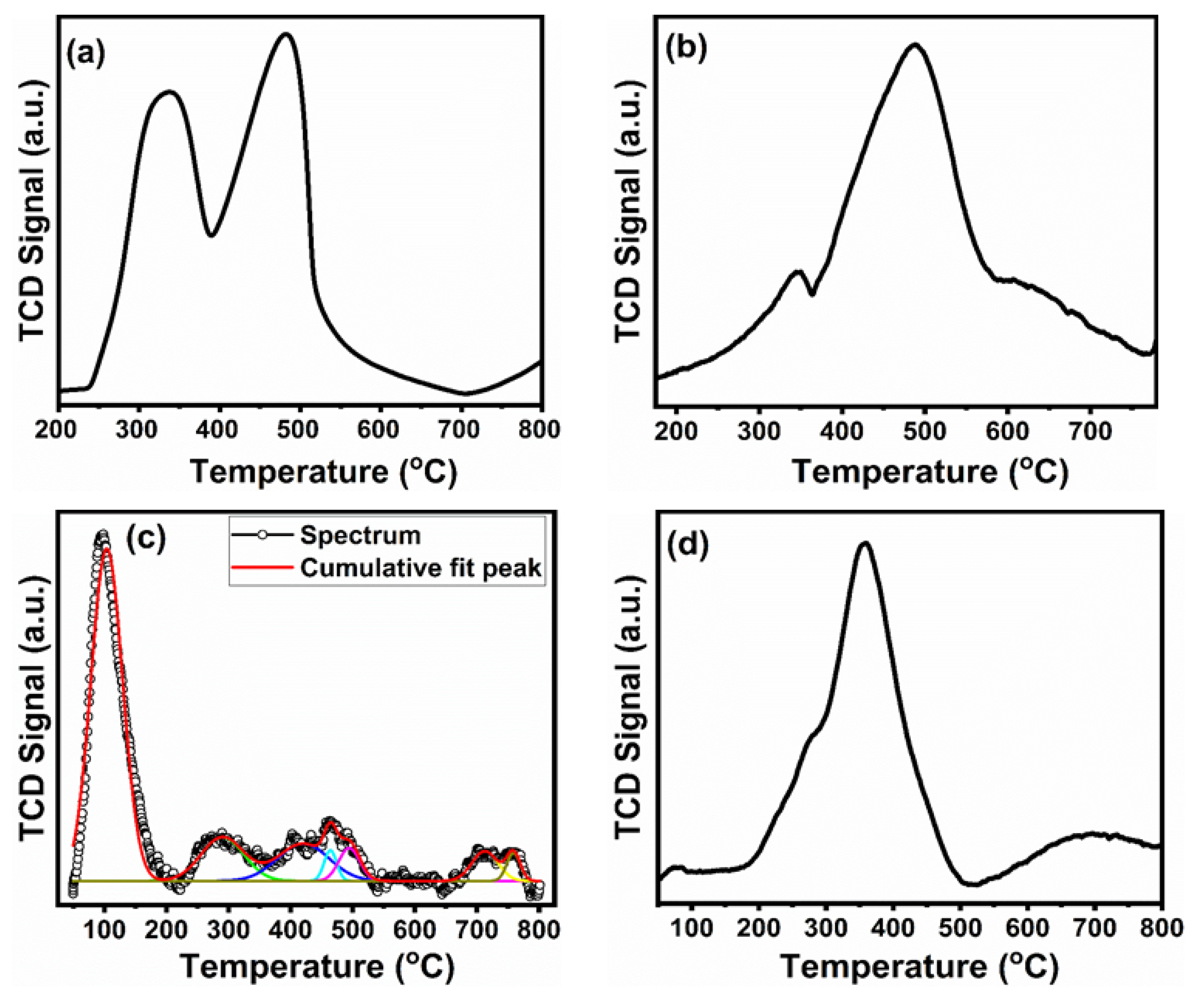
3.8. Temperature-Programmed Reactions (H2-TPR, O2-TPO, CO2-TPD)

Figure 9 shows reduction, oxidation, and desorption features of hexagonal BaNiO3 perovskite along with oxidation of the spent catalyst. Figure 9a presents a TPR profile of BaNiO3 which shows two peak at 335 °C and 485 °C. The first peak is caused by the partial reduction of BaNiO3 to Ba2NiO4 and the second peak by the complete reduction into metallic nickel in the presence of surface and bulk lattice oxygen, respectively [42,43]. In other words, the first peak results from the reduction of Ni3+ to Ni2+, and the second peak corresponds to the reduction of Ni2+ to Ni°, which remains deposited on cubic BaO, confirmed by XRD patterns of the reduced BaNiO3 perovskite oxide (Figure 3b). Fierro and Tejuca [48,49] studied the oxygen species of LaMO3 (M = Cr, Mn, Fe, Co, Ni) by XPS and found that the peak at low binding energy corresponded to the surface lattice oxygen, which can be reduced easily under reducing atmosphere. The peak at high binding energy corresponded to the bulk lattice oxygen, which is more stable in reduction medium. In terms of hydrogen consumption for the reduction process, it was observed that the second peak consumes more hydrogen than the first peak, evidenced the ideal condition for the DRM reaction [50]. After reoxidation, the first TPR (Figure 9b) shows a different shape, depicting one shoulder at 350 °C and another wide major peak at 470 °C, indicating the partial regeneration of fabricated perovskite.
To acquire the information on catalytic performance, the CO2-TPD experiment is one of the most important tools which provides information regarding the strength and number of basic sites present in the catalyst. It is well-reported that the strength of basic sites is increased with the adsorption of CO2 during the DRM reaction, which in turn aids the gasification of carbon species during CH4 decomposition and CO disproportionation [51,52]. The CO2-TPD curve of the catalyst is presented in Figure 9c. It is apparent from TPD profiles that prepared catalyst showed at least five CO2 desorption peaks: first major peak between 50–200 °C, a second minor peak between 200–350, a third minor peak with a shoulder between 350–550, and fourth and fifth above 650 °C, respectively. The low and high temperature peaks represent the weak and strong basic strength of the fabricated sample. It is suggested that the ability of the catalyst to chemisorb CO2 increases with increasing of its Lewis basicity, and CO2 chemisorption favors the elimination of different forms of carbon, produced by the side reactions.
The nature, structure, and amount of deposited carbon species on the catalyst during the DRM tests was determined by the quantification of oxidation products (CO2) by temperature-programmed oxidation (TPO) process. These carbons can be gasified to CO and/or CO2 under the oxidative atmosphere, at different temperatures: atomic carbon (Cα) < 250 °C, filamentous carbon (Cβ) 250~600 °C and graphitic carbon (Cγ) > 600 °C [53]. The first two types of carbon are reactive compared to graphitic carbon, moreover atomic and filamentous carbon have slower deactivation rate, while graphitic, being more inactive, has a rapid deactivation rate. Additionally, it is believed that Cα species are responsible for the formation of synthesis gas [53]. The TPO profiles for the spent catalysts are presented in Figure 9d, and show only one major peak centered in temperature range of 175–475 °C, covering a lesser peak area. It can be an atomic or filamentous type of carbon deposition, both having different degrees of reactivity. This suggests that that amount of carbon deposition is relatively less and is reactive. Therefore, covering a lesser peak area, the reactive carbon species indicate the fabricated catalysts have more coke-resistance capacity and are less prone to coke deposition during the DRM process. TPO results are in good agreement with the TGA results.

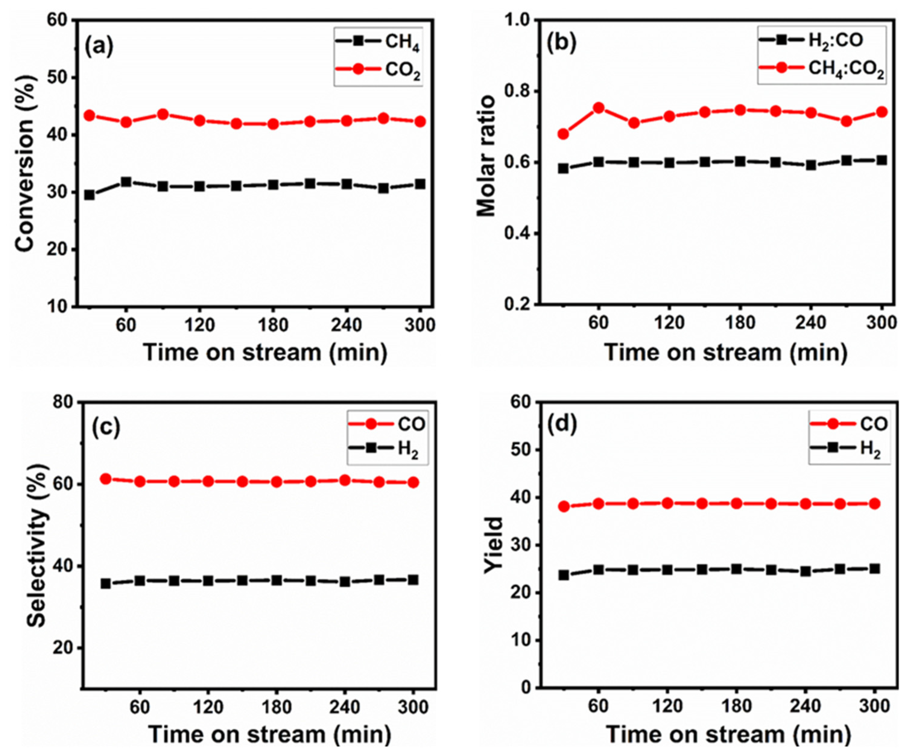
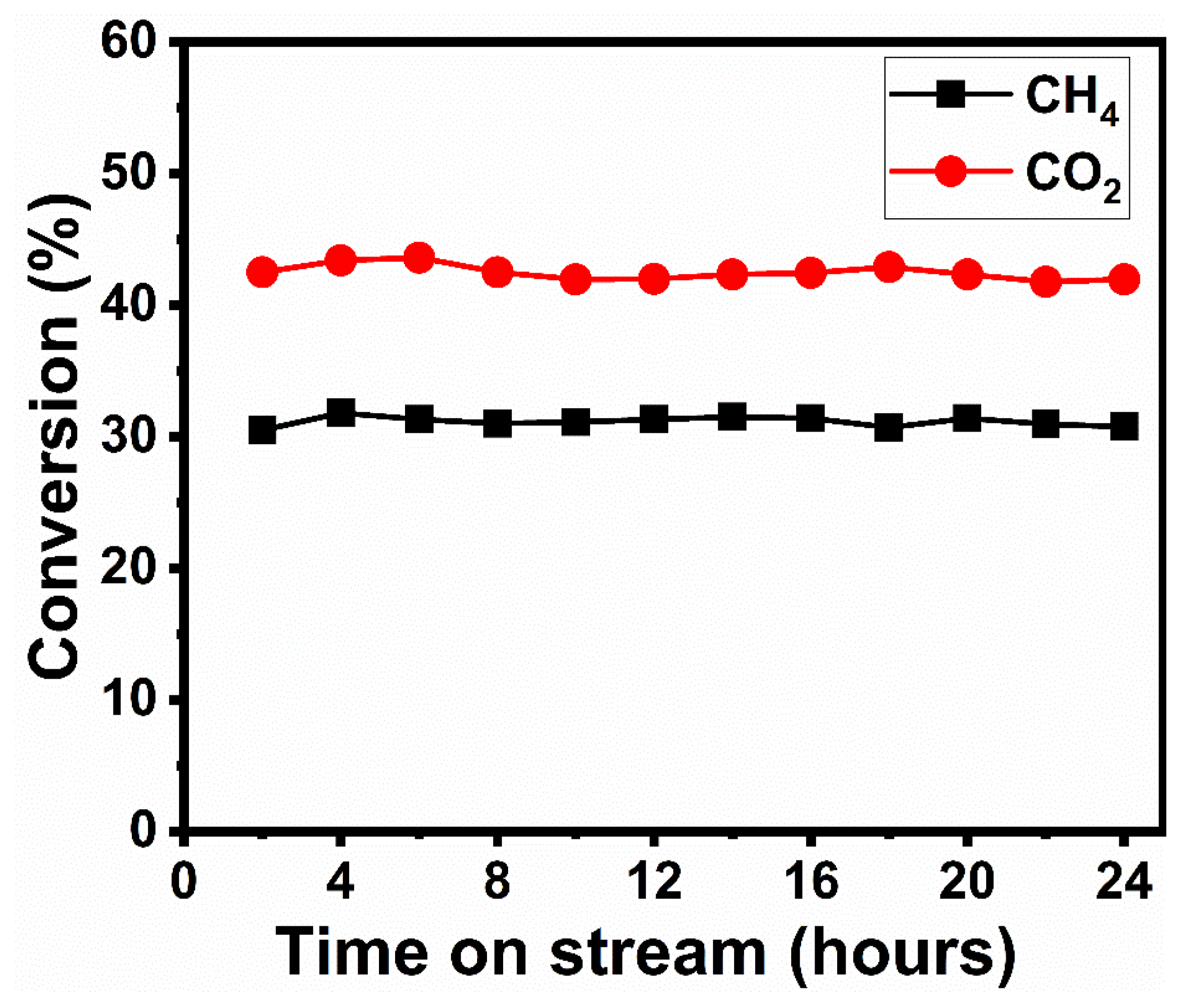
4. Catalytic Performance of Reduced Perovskite Precursor (r-BNO)

Before estimating the performances of the catalyst in the DRM process, the fabricated BaNiO3 perovskite was submitted for reduction by hydrogen at 700 °C for 3 h. Having a stabilized temperature, the equimolar mixture of CO2 and CH4 was passed through the catalyst bed. The catalytic stability test of the r-BNO catalyst has been tested for 5 h at reaction temperature (700 °C). The experimental data obtained from GC analyses of the products leaving the reactor, conversion (CH4, CO2), molar ratio (H2:CO, CH4:CO2), selectivity (CO, H2), and yield (CO, H2) were plotted as a function of reaction time (Figure 10). It was observed that stability tests continued for approximately 5 h without any interruption. Figure 10a shows the CH4 and CO2 conversion as a function of time of stream using a reactive gas mixture of CH4:CO2 equal to 1:1. The CH4 and CO2 conversions are equal to 31.5% and 42.33%, respectively, and molar ratio H2/CO is close to 0.6 (Figure 10b). Results shows that CO2 conversion is higher than CH4 conversion, therefore, the obtained H2/CO ratio is lower than unity. It was observed that the conversion remains unchanged after 5 h of reaction, and even a small increase could be assumed. The initial and final conversions of CH4 and CO2 changed from 29.5% to 31.4% and 43.39% to 42.33%, respectively for the catalyst. In fact, it was found that there is no declination in conversions due to deposition of carbon over the catalyst surface during the reaction. These findings are verified by TGA and TPO analyses of spent catalysts. Although their conversion rates were low, catalyst was stable at applied reaction conditions. At the same time, the main products, CO and H2, remain stable with a H2/CO ratios < 1 expected for the DRM reaction (CH4 + CO2 → 2CO + 2H2), which can be ascribed to some activity in the reverse WGSR (CO2 + H2 → CO + H2O) where the H2 produced during reaction further reacts with CO2 [54]. Therefore, more CO2 could be consumed in the reaction than expected. The literature reports that when H2/CO ratio is close to 1, it strongly suggests that the RWGS reaction did not proceed [55]. So, these results show that catalyst prepared by reductive decomposition of BaNiO3 is active and stable for all the studied methane reactions. Figure 10c,d shows selectivity and yield of components of synthesis gas. It was observed that the selectivity and the yield are unaffected during the course of the reaction, however, both parameters for CO are higher than H2, which implies that the little amount carbon deposition occurred according to the Boudouard reaction (2CO → C + CO2). On the basis of these observations, it is easy to say that the net rate of coke deposition on the catalyst surface is dependent on the relative rates of the carbon accumulation on the catalyst surface and its oxidative removal. The large amount of coke deposition or coking will take place when the rate of the oxidative removal is slower than the rate of carbon formation [56].
In order to obtain further information regarding the stability of catalyst under the same set of experimental conditions as for the 5 h stability test, the sample was run for 24 h. Figure 11 shows the conversion of CH4 and CO2 as a function of time on stream. It is observed that the r-BNO catalyst does not show remarkable differences in both cases.

5. Conclusions

The precipitation route is a simple method to fabricate a desired perovskite structure, BaNiO3. The XRD diffraction analysis showed that perovskite calcined at 750 °C is closer to the hexagonal phase. This work shows that a Ni/BaO catalyst under hydrogen atmosphere can be obtained that is active in the DRM reaction. The structural and surficial changes produced during the reaction were followed by techniques such as TGA, TPO, TEM, BET and XRD. It is important to point out that upon reoxidation treatments, most of the BaNiO3 phase is recovered from the reduced Ni/BaO catalyst, which could provide a convenient way to regenerate a waste catalyst. TEM measurement performed on the reduced and used catalyst reveal that the average nanoparticle size of reduced catalyst was smaller and more uniform than BaNiO3 nanoparticles, however, the size and shape of the spent catalyst was found to be higher due to sintering and aggregation of nanoparticles. Catalysts obtained by reduction of BaNiO3 showed more CO2 conversion than the CH4 due to RWGS however, but no deactivation in situ of material was observed after 5 and 24 h time on stream. However, the catalyst shows low catalytic activity in spite of no deactivation, so further improvement is necessary for the dispersion of Ni particles at the catalyst surface for the high activity.

Author Contributions

Conceptualization, N.A., F.A., and R.W.; methodology, F.A.; software, N.A.; validation, R.W.; formal analysis, F.A.; investigation, S.M.; resources, F.A.; data curation, B.F.A. and S.M.; writing—original draft preparation, N.A.; writing—review and editing, F.A. and R.W.; visualization, S.M.; supervision, F.A. and N.A.; project administration, N.A.; funding acquisition, N.A. All authors have read and agreed to the published version of the manuscript.

Funding

The authors would like to extend their sincere appreciation to the King Saud University for its funding to this NPST project (14-PET851-02).

Institutional Review Board Statement

Not applicable.

Informed Consent Statement

Not applicable.

Data Availability Statement

Not applicable.

Acknowledgments

The authors would like to extend their sincere appreciation to the King Saud University for its funding to this NPST project (14-PET851-02).

Conflicts of Interest

The authors declare no conflict of interest.

References

  1. Wood, D.; Nwaoha, C.; Towler, B. Gas-to-liquids (GTL): A review of an industry offering several routes for monetizing natural gas. J. Nat. Gas Sci. Eng. 2012, 9, 196–208. [Google Scholar] [CrossRef]
  2. Yagi, F.; Hodoshima, S.; Wakamatsu, S.; Kanai, R.; Kawazuishi, K.; Suehiro, Y.; Shimura, M. Development of CO2 reforming technology. Stud. Surf. Sci. Catal. 2007, 67, 385–390. [Google Scholar] [CrossRef]
  3. Bockris, J.O.M. The origin of ideas on a Hydrogen Economy and its solution to the decay of the environment. Int. J. Hydrogen Energy 2002, 27, 731–740. [Google Scholar] [CrossRef]
  4. Ueda, K.; Hirata, Y.; Sameshima, S.; Shimonosono, T.; Yamaji, K. Formation of hydrogen from the CO–H2O system using porous Gd-doped ceria electrochemical cell with MnO cathode and Fe3O4 anode. J. Asian Ceram. Soc. 2015, 3, 82–87. [Google Scholar] [CrossRef] [Green Version]
  5. Chen, P.; Zhang, H.-B.; Lin, G.-D.; Tsai, K.-R. Development of coking-resistant Ni-based catalyst for partial oxidation and CO2-reforming of methane to syngas. Appl. Catal. A Gen. 1998, 166, 343–350. [Google Scholar] [CrossRef]
  6. Bjørgen, M.; Kolboe, S. The conversion of methanol to hydrocarbons over dealuminated zeolite H-beta. Appl. Catal. A Gen. 2002, 225, 285–290. [Google Scholar] [CrossRef]
  7. Hartadi, Y.; Behm, R.J.; Widmann, D. Competition of CO and H2 for Active Oxygen Species during the Preferential CO Oxidation (PROX) on Au/TiO2 Catalysts. Catalysts 2016, 6, 21. [Google Scholar] [CrossRef]
  8. Arandiyan, H.; Li, J.; Ma, L.; Hashemnejad, S.; Mirzaei, M.; Chen, J.; Chang, H.; Liu, C.; Wang, C.; Chen, L. Methane reforming to syngas over LaNixFe1−xO3 (0 ≤ x ≤ 1) mixed-oxide perovskites in the presence of CO2 and O2. J. Ind. Eng. Chem. 2012, 18, 2103–2114. [Google Scholar] [CrossRef]
  9. Jiang, Y.; Shen, Q.; Li, S.; Yang, G.; Huang, N. B-site cobalt-doped perovskite oxide BaNiO3 oxygen sorbents for performance improvement of oxygen enriched gas production. New J. Chem. 2020, 44, 6003–6009. [Google Scholar] [CrossRef]
  10. Hou, Z.; Yokota, O.; Tanaka, T.; Yashima, T. Characterization of Ca-promoted Ni/α-Al2O3 catalyst for CH4 reforming with CO2. Appl. Catal. A Gen. 2003, 253, 381–387. [Google Scholar] [CrossRef]
  11. Guczi, L.; Koppány, Z.; Sarma, K.V.; Borkó, L.; Kiricsi, I. Structure and catalytic activity of Co-based bimetallic systems in NaY zeolite: Low temperature methane activation. In Studies in Surface Science and Catalysis; Elsevier: Amsterdam, The Netherlands, 1997; Volume 105, pp. 861–868. [Google Scholar] [CrossRef]
  12. Nam, J.W.; Chae, H.; Lee, S.H.; Jung, H.; Lee, K.Y. Methane dry reforming over well-dispersed Ni catalyst prepared from perovskite-type mixed oxides. Stud. Surf. Sci. Catal. 1998, 119, 843–848. [Google Scholar] [CrossRef]
  13. Zhang, R.-J.; Xia, G.-F.; Li, M.-F.; Wu, Y.; Nie, H.; Li, D.-D. Effect of support on the performance of Ni-based catalyst in methane dry reforming. J. Fuel Chem. Technol. 2015, 43, 1359–1365. [Google Scholar] [CrossRef]
  14. Wang, Y.; Yao, L.; Wang, Y.; Wang, S.; Zhao, Q.; Mao, D.; Hu, C. Low-Temperature Catalytic CO2 Dry Reforming of Methane on Ni-Si/ZrO2 Catalyst. ACS Catal. 2018, 8, 6495–6506. [Google Scholar] [CrossRef]
  15. Richardson, J.; Paripatyadar, S. Carbon dioxide reforming of methane with supported rhodium. Appl. Catal. 1990, 61, 293–309. [Google Scholar] [CrossRef]
  16. Ashcroft, A.T.; Cheetham, A.K.; Green, M.L.H.; Vernon, P.D.F. Partial oxidation of methane to synthesis gas using carbon dioxide. Nat. Cell Biol. 1991, 352, 225–226. [Google Scholar] [CrossRef]
  17. Solymosi, F.; Kutsan, G.; Erdohelyi, A. Catalytic reaction of CH4 with CO2 over alumina-supported Pt metals. Catal. Lett. 1991, 11, 149–156. [Google Scholar] [CrossRef]
  18. Wang, L.; Hu, R.; Liu, H.; Wei, Q.; Gong, D.; Mo, L.; Tao, H.; Zhang, Z. Encapsulated Ni@La2O3/SiO2 Catalyst with a One-Pot Method for the Dry Reforming of Methane. Catalysts 2019, 10, 38. [Google Scholar] [CrossRef] [Green Version]
  19. Zhang, Z.; Verykios, X.E. Carbon dioxide reforming of methane to synthesis gas over Ni/La2O3 catalysts. Appl. Catal. A Gen. 1996, 138, 109–133. [Google Scholar] [CrossRef]
  20. Hayakawa, T.; Suzuki, S.; Nakamura, J.; Uchijima, T.; Hamakawa, S.; Suzuki, K.; Shishido, T.; Takehira, K. CO2 reforming of CH4 over Ni/perovskite catalysts prepared by solid phase crystallization method. Appl. Catal. A Gen. 1999, 183, 273–285. [Google Scholar] [CrossRef]
  21. Zhang, Z.; Verykios, X.E. A stable and active nickel-based catalyst for carbon dioxide reforming of methane to synthesis gas. J. Chem. Soc. Chem. Commun. 1995, 71–72. [Google Scholar] [CrossRef]
  22. Shiozaki, R.; Andersen, A.G.; Hayakawa, T.; Hamakawa, S.; Suzuki, K.; Shimizu, M.; Takehira, K. Sustainable Ni/BaTiO3 catalysts for partial oxidation of methane to synthesis gas. Stud. Surf. Sci. Catal. 1997, 110, 701–710. [Google Scholar] [CrossRef]
  23. Batiot-Dupeyrat, C.; Valderrama, G.; Meneses-Jacome, A.; Martinez, F.; Barrault, J.; Tatibouët, J. Pulse study of CO2 reforming of methane over LaNiO3. Appl. Catal. A Gen. 2003, 248, 143–151. [Google Scholar] [CrossRef]
  24. Lago, R.; Bini, G.; Peña, M.A.; Fierro, J. Partial Oxidation of Methane to Synthesis Gas Using LnCoO3 Perovskites as Catalyst Precursors. J. Catal. 1997, 167, 198–209. [Google Scholar] [CrossRef]
  25. Tsipouriari, V.A.; Verykios, X.E. Kinetic study of the catalytic reforming of methane with carbon dioxide to synthesis gas over Ni/La2O3 catalyst. Catal. Today 2001, 64, 83–90. [Google Scholar] [CrossRef]
  26. Verykios, X.E. Catalytic dry reforming of natural gas for the production of chemicals and hydrogen. Int. J. Hydrogen Energy 2003, 28, 1045–1063. [Google Scholar] [CrossRef]
  27. Slagtern, Å.; Olsbye, U. Partial oxidation of methane to synthesis gas using La-M-O catalysts. Appl. Catal. A Gen. 1994, 110, 99–108. [Google Scholar] [CrossRef]
  28. Tao, K.; Shi, L.; Ma, Q.; Wang, D.; Zeng, C.; Kong, C.; Wu, M.; Chen, L.; Zhou, S.; Hu, Y.; et al. Methane reforming with carbon dioxide over mesoporous nickel–alumina composite catalyst. Chem. Eng. J. 2013, 221, 25–31. [Google Scholar] [CrossRef]
  29. Provendier, H.; Petit, C.; Estournes, C.; Libs, S.; Kiennemann, A. Stabilisation of active nickel catalysts in partial oxidation of methane to synthesis gas by iron addition. Appl. Catal. A Gen. 1999, 180, 163–173. [Google Scholar] [CrossRef]
  30. Rezaei, M.; Alavi, S.; Sahebdelfar, S.; Bai, P.; Liu, X.; Yan, Z.-F. CO2 reforming of CH4 over nanocrystalline zirconia-supported nickel catalysts. Appl. Catal. B Environ. 2008, 77, 346–354. [Google Scholar] [CrossRef]
  31. Tangwiwat, S.; Milne, S.J. Barium titanate sols prepared by a diol-based sol–gel route. J. Non-Cryst. Solids 2005, 351, 976–980. [Google Scholar] [CrossRef]
  32. Nikoofar, K.; Haghighi, M.; Khademi, Z. Preparation, characterization, and catalytic application of metallic nanocrystalline MgAl2O4 in the synthesis of 3-hydroxy-3-indolyl-indolin-2-ones, symmetrical and unsymmetrical 3,3′-bis(indolyl)indolin-2-ones, and 3,3′-bis(indolyl)methanes. Arab. J. Chem. 2019, 12, 3776–3784. [Google Scholar] [CrossRef] [Green Version]
  33. Miller, F.A.; Wilkins, C.H. Infrared Spectra and Characteristic Frequencies of Inorganic Ions. Anal. Chem. 1952, 24, 1253–1294. [Google Scholar] [CrossRef]
  34. Adekunle, A.S.; Oyekunle, J.A.O.; Oluwafemi, O.S. Comparative Catalytic Properties of Ni(OH) and NiO Nano-particles Towards the Degradation of Nitrite (NO2) and Nitric Oxide (NO). Int. J. Electrochem. Sci. 2014, 9, 3008–3021. [Google Scholar]
  35. Gottschall, R.; Schöllhorn, R.; Muhler, M.; Jansen, N.; Walcher, D.; Gütlich, P. Electronic State of Nickel in Barium Nickel Oxide, BaNiO3. Inorg. Chem. 1998, 37, 1513–1518. [Google Scholar] [CrossRef]
  36. Klug, H.P.; Alexander, L.E. X-ray Diffraction Procedures for Polycrystalline and Amorphous Materials; Wiley: London, UK, 1962. [Google Scholar] [CrossRef]
  37. Willander, M.; Nur, O.; Israr, M.Q.; Hamad, A.B.A.; El Desouky, F.G.; Salem, M.A.; Battisha, I.K. Determination of A.C. Conductivity of Nano-Composite Perovskite Ba1−x−ySrxTiFeyO3 Prepared by the Sol-Gel Technique. J. Cryst. Process. Technol. 2012, 2, 1–11. [Google Scholar] [CrossRef] [Green Version]
  38. Guo, R.; Fang, L.; Dong, W.; Zheng, F.; Shen, M. Enhanced Photocatalytic Activity and Ferromagnetism in Gd Doped BiFeO3 Nanoparticles. J. Phys. Chem. C 2010, 114, 21390–21396. [Google Scholar] [CrossRef]
  39. Yang, M.; He, J. Fine tuning of the morphology of copper oxide nanostructures and their application in ambient degradation of methylene blue. J. Colloid Interface Sci. 2011, 355, 15–22. [Google Scholar] [CrossRef] [PubMed]
  40. Wang, K.; Zhong, P.; Zhu, J.J. Preparation of Highly Active and Stable Perovskite-like Catalyst by Combustion Method: Effect of Complex. Catal. Lett. 2009, 131, 672–675. [Google Scholar] [CrossRef]
  41. Eltejaei, H.; Bozorgzadeh, H.R.; Towfighi, J.; Omidkhah, M.R.; Rezaei, M.; Zanganeh, R.; Zamaniyan, A.; Ghalam, A.Z. Methane dry reforming on Ni/Ce0.75Zr0.25O2–MgAl2O4 and Ni/Ce0.75Zr0.25O2–γ-alumina: Effects of support composition and water addition. Int. J. Hydrogen Energy 2012, 37, 4107–4118. [Google Scholar] [CrossRef]
  42. Liu, J.; Jiang, J.; Cheng, C.; Li, H.; Zhang, J.; Gong, H.; Fan, H.J. Co3O4 Nanowire@MnO2 Ultrathin Nanosheet Core/Shell Arrays: A New Class of High-Performance Pseudocapacitive Materials. Adv. Mater. 2011, 23, 2076–2081. [Google Scholar] [CrossRef] [PubMed]
  43. Yin, J.-W.; Yin, Y.-M.; Lu, J.; Zhang, C.; Minh, N.Q.; Ma, Z.-F. Structure and Properties of Novel Cobalt-Free Oxides NdxSr1–xFe0.8Cu0.2O3−δ (0.3 ≤ x ≤ 0.7) as Cathodes of Intermediate Temperature Solid Oxide Fuel Cells. J. Phys. Chem. C 2014, 118, 13357–13368. [Google Scholar] [CrossRef]
  44. Du, X.; Zhang, D.; Shi, L.; Gao, R.; Zhang, J. Morphology Dependence of Catalytic Properties of Ni/CeO2 Nanostructures for Carbon Dioxide Reforming of Methane. J. Phys. Chem. C 2012, 116, 10009–10016. [Google Scholar] [CrossRef]
  45. Kumar, R.; Rai, P.; Sharma, A. Free-standing NiV2S4 nanosheet arrays on a 3D Ni framework via an anion exchange reaction as a novel electrode for asymmetric supercapacitor applications. J. Mater. Chem. A 2016, 4, 17512–17520. [Google Scholar] [CrossRef]
  46. Lin, J.; Zhong, Z.; Wang, H.; Zheng, X.; Wang, Y.; Qi, J.; Cao, J.; Fei, W.; Huang, Y.; Feng, J. Rational constructing free-standing Se doped nickel-cobalt sulfides nanotubes as battery-type electrode for high-performance supercapattery. J. Power Sources 2018, 407, 6–13. [Google Scholar] [CrossRef]
  47. Miot, C.; Husson, E.; Proust, C.; Erre, R.; Coutures, J. X-ray Photoelectron Spectroscopy Characterization of Barium Titanate Ceramics Prepared by the Citric Route: Residual Carbon Study. J. Mater. Res. 1997, 12, 2388–2392. [Google Scholar] [CrossRef]
  48. Fierro, J.; Tejuca, L. Non-stoichiometric surface behaviour of LaMO3 oxides as evidenced by XPS. Appl. Surf. Sci. 1987, 27, 453–457. [Google Scholar] [CrossRef]
  49. Tejuca, L.G.; Fierro, J.L.G. XPS and TPD probe techniques for the study of LaNiO3 perovskite oxide. Thermochim. Acta 1989, 147, 361–375. [Google Scholar] [CrossRef]
  50. De Lima, S.M.; Assaf, J. Ni–Fe Catalysts Based on Perovskite-type Oxides for Dry Reforming of Methane to Syngas. Catal. Lett. 2006, 108, 63–70. [Google Scholar] [CrossRef]
  51. Pino, L.; Vita, A.; Cipitì, F.; Laganà, M.; Recupero, V. Hydrogen production by methane tri-reforming process over Ni–ceria catalysts: Effect of La-doping. Appl. Catal. B Environ. 2011, 104, 64–73. [Google Scholar] [CrossRef]
  52. Koo, K.Y.; Roh, H.-S.; Jung, U.H.; Seo, D.J.; Seo, Y.-S.; Yoon, W.L. Combined H2O and CO2 reforming of CH4 over nano-sized Ni/MgO-Al2O3 catalysts for synthesis gas production for gas to liquid (GTL): Effect of Mg/Al mixed ratio on coke formation. Catal. Today 2009, 146, 166–171. [Google Scholar] [CrossRef]
  53. Guo, J.; Lou, H.; Zheng, X. The deposition of coke from methane on a Ni/MgAl2O4 catalyst. Carbon 2007, 45, 1314–1321. [Google Scholar] [CrossRef]
  54. Wu, Y.; Kawaguchi, O.; Matsuda, T. Catalytic Reforming of Methane with Carbon Dioxide on LaBO3 (B = Co, Ni, Fe, Cr) Catalysts. Bull. Chem. Soc. Jpn. 1998, 71, 563–572. [Google Scholar] [CrossRef]
  55. Dupeyrat, C.B.; Gallego, G.A.S.; Mondragon, F. CO2 reforming of methane over LaNiO3 as precursor material. Catal. Today 2005, 107–108, 474–480. [Google Scholar] [CrossRef]
  56. Takanabe, K.; Nagaoka, K.; Nariai, K.; Aika, K. Influence of reduction temperature on the catalytic behavior of Co/TiO2 catalysts for CH4/CO2 reforming and its relation with titania bulk crystal structure. J. Catal. 2005, 230, 75–85. [Google Scholar] [CrossRef]
Scheme 1. Schematic representation of BaNiO3 synthesis.
Sustainability 13 13855 sch001
Figure 1. TG-DTG profiles of (a) perovskite precursor (b) spent catalyst.
Sustainability 13 13855 g001
Figure 2. FTIR spectra of (a) perovskite precursor (b) BaNiO3 perovskite.
Sustainability 13 13855 g002
Figure 3. X-ray diffraction (XRD) patterns of (a) calcined (b) reduced BaNiO3 perovskite.
Sustainability 13 13855 g003
Figure 4. UV–vis spectrum of BaNiO3 perovskite oxide; Inset: optical band-gap energy.
Sustainability 13 13855 g004
Figure 5. SEM images of BaNiO3 perovskite at (a,b) Low magnification and (c) high magnification.
Sustainability 13 13855 g005
Figure 6. TEM images of (a,b) fresh, (c,d) reduced, and (e,f) used catalyst at various magnification.
Sustainability 13 13855 g006
Figure 7. (a) Adsorption–desorption isotherm and (b) BJH pore size distribution curve for BaNiO3 perovskite.
Sustainability 13 13855 g007
Figure 8. XPS spectra of BaNiO3 perovskite: (a) survey (b) O1s (c) Ni2p3/4 (d) Ba3d5/4 spectra.
Sustainability 13 13855 g008
Figure 9. (a) TPR, (b) TPO and (c) CO2-TPD (d) Spent TPO profiles of BaNiO3 perovskite.
Sustainability 13 13855 g009
Figure 10. (a) CH4 and CO2 conversion, (b) H2:CO and CH4:CO2 molar ratio (c) CO and H2 selectivity (d) CO and H2 yield. Reaction conditions: T = 700 °C; molar ratio CO2/CH4 = 1; F/W = 60 mL/mingcat.
Sustainability 13 13855 g010
Figure 11. CH4 and CO2 conversion, Reaction conditions: T = 700 °C; molar ratio CO2/CH4 = 1; F/W = 60 mL/mingcat.
Sustainability 13 13855 g011
Publisher’s Note: MDPI stays neutral with regard to jurisdictional claims in published maps and institutional affiliations.

