
Polarity Asymmetry in Lightning Return Stroke Speed Caused by the Momentum Associated with Radiation


1
Department of Electrical Engineering, Uppsala University, 752 37 Uppsala, Sweden
2
Karolinska Institute, 171 77 Stockholm, Sweden
3
HEIG-VD, University of Applied Sciences and Arts Western Switzerland, 1401 Yverdon-les-Bains, Switzerland
4
Electromagnetic Compatibility Laboratory, Swiss Federal Institute of Technology (EPFL), 1015 Lausanne, Switzerland
*
Author to whom correspondence should be addressed.
Atmosphere 2021, 12(12), 1642; https://doi.org/10.3390/atmos12121642
Submission received: 16 November 2021
/
Revised: 29 November 2021
/
Accepted: 29 November 2021
/
Published: 8 December 2021
(This article belongs to the Special Issue Feature Papers in Atmosphere Science)
Abstract
:In positive lightning return strokes, the net momentum transported by the radiation field has the same direction as the momentum associated with electrons, whereas the momentum associated with electrons is in opposite direction to the momentum of radiation in negative return strokes. It is shown here that this polarity asymmetry could limit the maximum speed of positive return strokes with respect to the negative return strokes.
1. Introduction
The basic components of a lightning flash can be separated into streamers, leaders and return strokes [1]. These discharge components exist in two polarities, namely, positive and negative. In positive streamers, positive leaders and return strokes in negative ground flashes, electrons travel in the opposite direction to the direction of the development of the discharge, while in negative streamers, negative leaders and return strokes in positive ground flashes electrons travel in the same direction as the direction of the propagation of the discharge.
Features of the currents and speeds of propagation differ in general in electrical discharges of positive and negative polarity [2,3]. Moreover, the electric fields necessary to support these discharges differ for negative and positive polarity [3]. Some of these differences are caused by the direction of propagation of the electrons with respect to the direction of propagation of the discharge. In positive polarity discharges, the direction of propagation of electrons is opposite to the direction of propagation of the discharge, whereas in negative polarity, the two directions are the same. In electrical discharges, it is the movement of the electrons that controls the main features of the electric discharges because the positive charges remain more or less stationary at the places where they were created during the propagation of the discharge. Several polarity asymmetries observed in lightning flashes were discussed previously by Williams [4]. One example considered in [4] relates to the way in which charges are transferred in ground flashes. In general, negative flashes transfer charge in several return strokes, whereas in positive ground flashes, most of the charge is transferred in a single stroke. Williams [4] suggested that such differences are caused by asymmetry in the mobilities of electrons and positive ions.
The goal of this paper is to illustrate the polarity asymmetry in electrical discharges caused by the momentum associated with the electron movement and the radiation emitted by the discharge. Though the theory presented can be applied to any type of electrical discharge, here, we will concentrate on the return strokes.
2. The Polarity Asymmetry Associated with the Direction of Movement of Charge Carriers
In the case of negative return strokes, the return stroke current is maintained by the movement of electrons towards the ground along the existing leader channel. On the other hand, the return stroke propagates upwards towards the cloud. Thus, the direction of propagation of the electrons is opposite to that of the return stroke. In the case of positive return strokes, electrons move towards the cloud and, thus, their direction of propagation is the same as the direction of propagation of the return stroke. Due to this polarity asymmetry, the electric and magnetic field at any point in space has opposite polarity in positive and negative return strokes. However, since the Poynting vector is given by , the energy and momentum associated with the radiation fields propagate in the same direction at any given point in space in both positive and negative return strokes.
In the case of vertical return strokes, the azimuthal symmetry of the electromagnetic field makes the net component of the momentum associated with the electromagnetic field equal to zero, except in the direction of propagation of the return stroke front, i.e., the positive z-direction. Thus, the momentum transported by the radiation field of positive return strokes has the opposite direction to the movement or the momentum of the electrons, whereas in negative return strokes, they have the same direction. This asymmetry of the direction of the radiation momentum and the direction of momentum associated with the electrons has a significant influence on the speed of propagation of positive strokes in comparison to negative return strokes. Before proceeding further, however, let us consider the momentum transported by the radiation fields of return strokes.
3. Momentum Transported by the Radiation Field
Electromagnetic fields transport momentum as well as energy. The flux of momentum transported by the electromagnetic field (rate of momentum transport per unit area) is given by [2]. Due to symmetry, the net momentum transported by the radiation field of a positive or a negative return stroke, which is assumed to be straight and vertical, is directed along the z-axis. In the analysis, we will first derive the momentum transported by the radiation field from a return stroke channel located in free space and the equations will be modified later to take into account the presence of the ground plane.
3.1. Expression for the Momentum Transported by the Radiation Field in the Absence of the Ground Plane
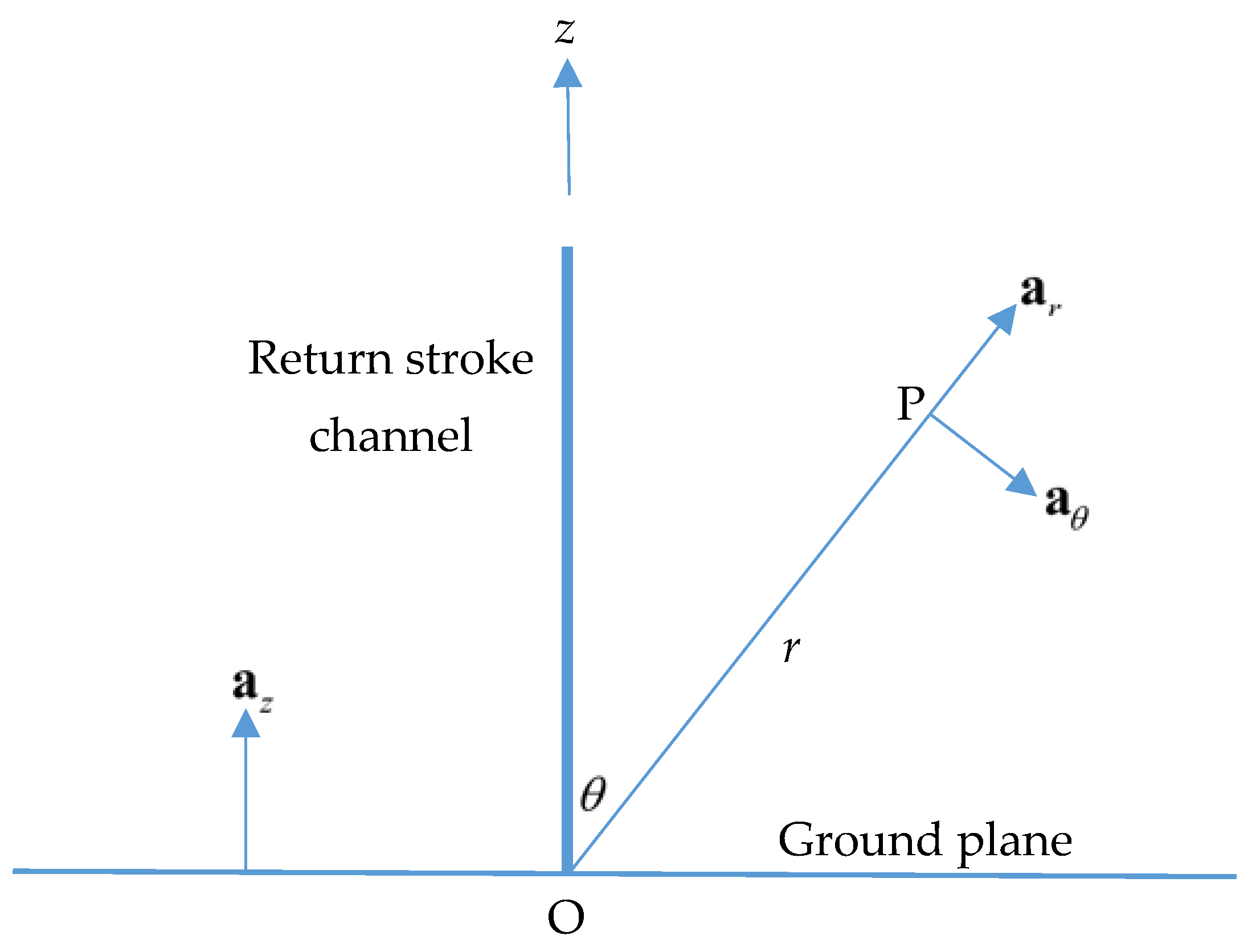
In the analysis, we consider a scenario similar to that of the transmission line model of the return stroke, where a current pulse propagates along a vertical channel with a constant speed without attenuation [5]. We consider the channel to be in free space with one end, where the current is injected, located at , and the channel to be oriented along the positive z-direction. The momentum in the positive z-direction and the positive current of return strokes in negative ground flashes moving in the positive z-direction are considered to have positive polarity. In the analysis, we assume that the current waveform propagating along the channel is a step function with peak amplitude . However, we derive the equations pertinent to any arbitrary channel-base current waveform denoted here by . The geometry necessary for the analysis is shown in Figure 1. The electric and magnetic radiation fields at point P generated by a return stroke simulated by the transmission line model are given by [6]
and
The Poynting vector associated with this wave is then given by
The flux of momentum associated with this radiation field passing through a unit area placed perpendicular to the propagation of the wave at point P is given by
The z-component of this momentum flux is given by
Due to symmetry, only the z-component of the net momentum flux exists, and the rate of change of the total momentum can be obtained by integrating over a sphere with the center at the point of current injection into the channel. The rate of change of the total momentum in the z-direction associated with this wave is thus given by
This integral can be evaluated analytically, and the result with is given by [7]
Note that, irrespective of the polarity of the current, the total momentum is always directed along the positive z-direction. That is, for both positive and negative currents, has a positive sign. In the case of a step function current of amplitude , the above equation reduces to (for )
3.2. Expression for the Momentum Transported by the Radiation Field in the Presence of the Ground Plane
In the presence of the ground plane, the z-momentum associated with the radiation field can be obtained directly from the equations presented earlier, noting that in calculating the electromagnetic field, the ground plane can be replaced by an image channel. The geometry relevant to the analysis is presented in Figure 2. In this case, the radiation field exists only in the upper half space, and it is given at point P by [6]
The first term comes from the direct channel and the second term comes from the image. This can be simplified to
The corresponding magnetic field is given by
The flux of momentum associated with this radiation field passing through a unit area placed perpendicular to the propagation of the wave at point P is given by
The z-component of this momentum flux is given by
Again, due to symmetry, only the z-component of the net momentum flux exists, and the rate of change of the total momentum can be obtained by integrating over a sphere with the center at the point of current injection into the channel. The rate of change of the total momentum in the z-direction associated with this wave is thus given by Equation (14) (note that the upper limit of the integral over is equal to because the radiation exists only over the upper half plane above the perfectly conducting ground).
This integral can be evaluated analytically, and the result with is given by
In the case of a step function current of amplitude , the above equation reduces to
4. The z-Component of the Momentum Associated with the Drift of Electrons in the Channel
Now, let us consider the movement of electrons in the channel. Consider a channel element of unit length of the return stroke channel. We consider the return stroke current waveform to be a step function of amplitude . The current in this channel element is related to the drift speed by the equation
In the above equation, is the density of electrons in the channel, e is the elementary charge and is the radius of the circular cross-section of the channel. The z-momentum of the electrons in the channel element of unit length associated with their drift is then given by
In the above equation, is the mass of the electron. Now, consider the change in momentum of the electrons in the return stroke channel during the time interval . During this time interval, a channel length equal to . is fed by the source with a current of magnitude . Thus, the increase in the momentum of the electrons during that time interval is given by
This can be written as
Thus, the rate of increase in the momentum of electrons at time is given by
5. Momentum Balance in Return Strokes
Just before the initiation of the return stroke, the leader travels down from the cloud, lowering the charge toward the ground. The electric field created by this charge and the remaining charge in the cloud are the sources that drive the return stroke along the channel. Let us consider a positive return stroke where the electrons are moving towards the cloud, i.e., in the direction of the positive z-axis. Let us denote by the force exerted by the source (i.e., the electric field) on the electrons in the channel (note that, in the case of positive return strokes, the electric field is directed along the negative z-axis), which can be related to the time derivative of the momentum. This force accelerates negative charges or electrons towards the positive z-direction. This force is responsible for the momentum of electrons in the return stroke channel. Let us now consider the momentum balance along the z-axis for the movement of electrons for positive and negative return strokes during the time interval .
5.1. Positive Return Strokes
Let us represent the current and the speed of the positive return stroke by and , respectively. We assume that this combination is allowed by energy conservation. The momentum balance equation for this positive return stroke is given by
In the above equation, is the momentum lost by electrons in collisions and in other interactions during the time when the electrons have increased their speed from zero to . The last two terms represent the rate of change of momentum gained by electrons and the momentum radiated away, respectively. Substituting for the radiation term, for a return stroke in free space (Equation (8)), and taking into account (22), we obtain
In the case of a discharge channel over perfectly conducting ground, we obtain
5.2. Negative Return Strokes
Just to illustrate a point, consider a negative return stroke where the current is transported purely by positrons. In this case, the positrons move in the direction of the positive z-axis and the momentum balance equations will be identical to the ones given in Equations (23) and (24). Now, consider a negative return stroke mediated by electrons. In this case, the electrons move towards the ground, and the direction of the momentum associated with the electrons is opposite to that of positrons, giving rise to an identical return stroke. The momentum balance equation for a negative return stroke with a current and a speed (again assuming this combination is allowed by energy conservation) located in free space is given by
Observe that the forward momentum is now given by the radiation field alone, while the electrons have momentum towards the negative z-axis. This can be written as
In the case of a return stroke over perfectly conducting ground, we obtain
6. Results
Let us consider negative return strokes. Observe that, according to (26), the condition
is satisfied for a channel in free space when
For a discharge channel over perfectly conducting ground, this condition is satisfied when
These conditions are realized when the momentum associated with the radiation overwhelms the momentum associated with electrons, while the momentum loss term becomes larger than the momentum input from the external source. Thanks to the opposite sign of the momentum associated with the radiation field, the source term can still drive a return stroke even when the losses overwhelm the source term. However, the situation is different in the case of positive return strokes. The momentum balance equations show that no positive return stroke can exist when because, in this case, the momentum balance equation cannot be satisfied (see Equation (24)). Hence, the speed and currents of positive return strokes should be such that . In other words, in positive return strokes, the momentum associated with the electrons always has to overwhelm the radiation momentum.
For a given positive return stroke current, there is a certain return stroke speed at which the radiation term overwhelms the electron momentum term. This speed decreases as the return stroke current increases. Figure 3 depicts the limiting speed above which the rate of change of the radiation momentum overwhelms the rate of change of the electron momentum as a function of the return stroke current. Note that for a given current, the limiting speed is lower in the case of a channel above perfectly conducting ground. The reason for this is the enhancement of the radiation field for a given current when the channel is located over perfectly conducting ground. For positive return strokes above perfectly conducting ground, the limiting speeds for currents of 250 kA, 100 kA, 30 kA and 5 kA are 4.0 × 10⁷ m/s, 9.4 × 10⁷ m/s, 2.1 × 10⁸ m/s and 2.98 × 10⁸ m/s, respectively. Such restrictions do not apply to negative return strokes. For example, while the speed of a positive return stroke with a 100 kA current is limited to 9.4 × 10⁷ m/s, a negative return stroke with an identical current can propagate with larger speeds, even speeds exceeding 2.0 × 10⁸ m/s. Note also that for return stroke currents lower than about 20 kA, the polarity asymmetry does not play any role because the limiting speed is almost equal to the speed of light. The results show that the polarity asymmetry associated with the electrons and the radiation field causes the positive return strokes to propagate with a speed that is lower than the speed possible for a negative return stroke with an identical current. It is important to point out that the values of the speeds given above are based on the assumption that the current waveform can be represented by a step pulse. However, real return stroke current waveforms differ from this ideal picture considerably. Moreover, in general, the return stroke speed is measured over channel lengths of several hundred meters to several kilometers, and the return stroke current waveform may change its shape considerably over such distances [8,9,10]. For these reasons, the limiting values of the speeds given above may differ from the limiting values of the speeds of actual return strokes.
7. Discussion
It is important to point out that what we have presented in Section 6 are the limiting speeds associated with positive return strokes due to the momentum balance associated with the radiation and electrons. This does not mean that the positive return strokes need to propagate at the limiting speeds. It is possible that due to other considerations involving, for example, channel properties, return strokes may propagate at speeds lower than the limiting values indicated in Section 6.
In the analysis presented in this paper, we assumed that the return stroke current and the speed are given, and we evaluated the consequences of the momentum balance equation. However, there are other considerations such as energy conservation that one has to consider in deciding whether a return stroke with a given current can propagate with a certain speed. Of course, the energy balance equation does not make any discrimination between positive and negative return strokes. However, it may play an important role in deciding whether a given return stroke current can be associated with a given return stroke speed. It is possible that the selection of the return stroke speed and the current has to be confined within the principle of energy conservation. However, the values we have considered in this paper belong to the range of lightning currents and speeds measured in practice.
In the literature, one can find only a few studies where the speeds of positive return strokes are measured [8,9,10]. Idone et al. [8] presented the measured speed of a positive return stroke in triggered lightning flashes. The measured speed was about 108 m/s. However, the peak current in the return stroke was about 20 kA, and for this reason, it could not be used to test the theoretical predictions presented here. In another paper, Mach and Rust [9] measured the speed of two positive return strokes with speeds of 108 m/s and 1.7 × 10⁸ m/s. They estimated the currents in these return strokes to be about 125 kA. However, they pointed out that the estimated current can be about 1.5 times the actual current due to the various assumptions used in estimating the peak current. In another paper [10], Mach and Rust studied the speed of propagation for a larger collection of positive return strokes. According to their results, the average speed of natural positive first return strokes over channel segments less than 500 m starting near the channel base is about 0.8 × 10⁸ m/s, whereas the corresponding speed for natural negative return strokes is 1.7 × 10⁸, which is considerably faster than that of the positive return strokes. These results are in agreement with the predictions made in this paper. However, in order to test the predictions made in this paper, it is necessary to have a dataset of measured speeds of both positive and negative return strokes with currents in the range of 80–125 kA or more.
8. Conclusions
In this paper, the effects of net momentum transported by the radiation field on the speed of propagation of the current along the return stroke channel were investigated. It was shown that, given identical initiating conditions, a positive return stroke will travel with a lower speed in comparison to a negative return stroke. The effect can be negligible for small currents, but it becomes highly significant for large currents.
Author Contributions
V.C. conceived the idea, developed the mathematics and the computer software and generated the data. All authors contributed equally in the analysis and in writing the paper. All authors have read and agreed to the published version of the manuscript.
Funding
This work was supported by the B. John F. and Svea Andersson donation at Uppsala University.
Conflicts of Interest
The authors declare no conflict of interest.
References
- Cooray, V. Mechanism of Electrical Discharges. In The Lightning Flash, 2nd ed.; Cooray, V., Ed.; IET Publishers: London, UK, 2014. [Google Scholar]
- Gallimberti, I. The mechanism of the long spark formation. J. Phys. Colloq. 1979, 40, 193–250. [Google Scholar] [CrossRef]
- Les Renardières Group. Research on long gap discharges at Les Renardières. Electra 1972, 23, 53–157. [Google Scholar]
- Williams, E. Problems in lightning physics—The role of polarity asymmetry. Plasma Sources Sci. Technol. 2006, 15, S91–S108. [Google Scholar] [CrossRef] [Green Version]
- Uman, M.A.; McLain, D.K. Magnetic field of lightning return stroke. J. Geophys. Res. 1969, 74, 6899–6910. [Google Scholar] [CrossRef]
- Cooray, V.; Cooray, G. On the Momentum Transported by the Radiation Field of a Long Transient Dipole and Time Energy Uncertainty Principle. Atmosphere 2016, 7, 151. [Google Scholar] [CrossRef] [Green Version]
- Cooray, V.; Cooray, G. Novel Features of Classical Electrodynamics and Their Connection to the Elementary Charge, Energy Density of Vacuum and Heisenberg’s Uncertainty Principle—Review and Consolidation. J. Mod. Phys. 2019, 10, 74–90. [Google Scholar] [CrossRef] [Green Version]
- Idone, V.P.; Orville, R.E. The propagation speed of a positive return stroke. Geophys. Res. Lett. 1987, 14, 1150–1153. [Google Scholar] [CrossRef] [Green Version]
- Mach, M.; Rust, W.D. Photoelectric Return-Stroke Velocity and Peak Current Estimates in Natural and Triggered Lightning. J. Geophys. Res. 1989, 94, 237–247. [Google Scholar] [CrossRef]
- Mach, M.; Rust, W.D. Two-Dimensional Velocity, Optical Risetime, and Peak Current Estimates for Natural Positive Lightning Return Strokes. J. Geophys. Res. 1993, 98, 2635–2638. [Google Scholar] [CrossRef]
Figure 1.
Geometry necessary for the analysis of the radiation field from a channel in free space. The vectors and are, respectively, unit vectors in the increasing direction of and (or OP). The vector is given by . The vector is directed towards .
Figure 1.
Geometry necessary for the analysis of the radiation field from a channel in free space. The vectors and are, respectively, unit vectors in the increasing direction of and (or OP). The vector is given by . The vector is directed towards .

Figure 2.
Geometry necessary for the analysis of the radiation field from a channel located over a perfectly conducting ground plane. The vectors and are unit vectors in the increasing direction of and (or OP). The vector is given by . The vector is directed towards .
Figure 2.
Geometry necessary for the analysis of the radiation field from a channel located over a perfectly conducting ground plane. The vectors and are unit vectors in the increasing direction of and (or OP). The vector is given by . The vector is directed towards .

Figure 3.
The limiting speed for a given positive return stroke current where the rate of change of momentum transported by the radiation field overwhelms the rate of change of the momentum of the electrons. The blue curve (upper curve) corresponds to a return stroke channel in free space, and the red curve (lower curve) corresponds to a return stroke channel over perfectly conducting ground.

Publisher’s Note: MDPI stays neutral with regard to jurisdictional claims in published maps and institutional affiliations. |
© 2021 by the authors. Licensee MDPI, Basel, Switzerland. This article is an open access article distributed under the terms and conditions of the Creative Commons Attribution (CC BY) license (https://creativecommons.org/licenses/by/4.0/).
Share and Cite
MDPI and ACS Style
Cooray, V.; Cooray, G.; Rubinstein, M.; Rachidi, F. Polarity Asymmetry in Lightning Return Stroke Speed Caused by the Momentum Associated with Radiation. Atmosphere 2021, 12, 1642. https://doi.org/10.3390/atmos12121642
AMA Style
Cooray V, Cooray G, Rubinstein M, Rachidi F. Polarity Asymmetry in Lightning Return Stroke Speed Caused by the Momentum Associated with Radiation. Atmosphere. 2021; 12(12):1642. https://doi.org/10.3390/atmos12121642
Chicago/Turabian StyleCooray, Vernon, Gerald Cooray, Marcos Rubinstein, and Farhad Rachidi. 2021. "Polarity Asymmetry in Lightning Return Stroke Speed Caused by the Momentum Associated with Radiation" Atmosphere 12, no. 12: 1642. https://doi.org/10.3390/atmos12121642
Note that from the first issue of 2016, this journal uses article numbers instead of page numbers. See further details here.