Article

Design and Experiment of Hydraulic Scouring System of Wide-Width Lotus Root Digging Machine

1
College of Engineering, Huazhong Agricultural University, Wuhan 430070, China
2
Key Laboratory of Agricultural Equipment in Mid-Lower Yangtze River, Ministry of Agriculture and Rural Affairs, Wuhan 430070, China
*
Author to whom correspondence should be addressed.
Agriculture 2021, 11(11), 1110; https://doi.org/10.3390/agriculture11111110
Submission received: 29 September 2021 / Revised: 4 November 2021 / Accepted: 4 November 2021 / Published: 7 November 2021
(This article belongs to the Section Agricultural Technology)

Abstract

:
In response to the problems of small working width and low operating efficiency of existing hydraulic scouring lotus root harvesters, a wide-width hydraulic scouring system was designed based on a wide-width self-propelled lotus root harvester. The main parameters of the key components were determined through theoretical analysis of the water flow energy of the hydraulic scouring system pipelines. An experimental study was also carried out on the main factors affecting the working performance of this hydraulic scouring system. Through hydrodynamic simulation tests, the effect of nozzle type and constriction section structure on the turbulence intensity at the nozzle outlet and the pressure loss per unit mass of fluid between the nozzle inlet and outlet sections were compared and analysed. The test yielded conical-cylindrical nozzle geometry parameters for nozzle inlet diameter of 40 mm, shrinkage angle of 30°, nozzle outlet straight section length of 20 mm, nozzle outlet diameter of 16 mm, the nozzle had better flushing performance. Single-factor tests were carried out with nozzle outlet pressure, scouring angle and nozzle height from the mud surface as influencing factors. Based on the optimum effective scour depth, a three-factor, three-level Box–Behnken central combination design test was completed. The primary and secondary factors affecting the effective scouring depth were obtained in the following order: nozzle height from the mud surface, nozzle outlet pressure, and scouring angle. Finally, the performance test of the hydraulic scouring system was completed. Results showed that when the nozzle outlet pressure of 0.30 MPa, the scouring angle of 60° and the nozzle height from the mud surface of 0 mm, the effective scouring depth was 395 mm, the lotus root floating rate was 90% and the damage rate was 5%, which meet the requirements of lotus root harvesting operations.

1. Introduction

Lotus root, a popular aquatic vegetable, is being grown in China year after year. According to incomplete statistics, as of 2019, more than 60,000 hectares of lotus roots were grown in Hubei province. Producing nearly 2000 Kg of lotus roots per 667 m2, the lotus root industry has good economic benefits [1]. More and more lotus roots need to be harvested in time. In the past, people usually used shovels to plough the soil on the surface of the lotus roots to complete the harvest. On the other way, people with high-pressure water guns use water jets to impact the soil above the lotus roots, causing them to float upwards on their own buoyancy and complete the harvest. In both cases, the harvesting method is labour intensive and inefficient [2,3,4]. The development of mechanised lotus root harvesting is the way to solve the current situation of lotus root harvesting difficulties.
To reduce the labour intensity of lotus root harvesting, research institutions and scholars at home and abroad have carried out a great number of researches on lotus root harvesting machinery. Overseas, Japan developed three models of floating root diggers with high-pressure pumps around traction-type hydrodynamic scouring root diggers. Because these root diggers move by a rope tow, so the mobility of this series of diggers was so poor. And the difference between the large area planted with lotus roots in China and the small plot planting in Japan, therefore they are not adapted to large-scale planting operations in China [5]. In China, research on lotus root harvesting machinery at research institutions such as Huazhong Agricultural University, Nanjing Agricultural University and the Hefei University of Technology can be divided into two main categories: floating root diggers and boat-type root diggers. Both types of lotus root harvesting machines use high-pressure water jets to disperse the soil on the surface of the lotus root, which floats upwards to achieve the purpose of lotus root harvesting. The floating root digger, with its simple structure and small working width, is suitable for plot block lotus root harvesting operations [6]. Boat root digger with paddy tractor as drive chassis. The water pump, delivery line and nozzles make up the hydraulic flushing system, which is arranged on the drive chassis. Usually, this type of machine has sufficient power and is fitted with several nozzles, to improve operational efficiency. It is suitable for large-scale planting and harvesting operations [7,8]. Currently, boat-type root diggers are developing in the direction of a wide self-propelled type [9,10].
Both types of lotus root harvesting machinery mentioned above are hydro-scouring types. In lotus root harvesting operations, if the water jet pressure is too low, the operation will be inefficient. Conversely, if the water jet pressure is too high, the lotus roots will be prone to breakage and damage and the energy consumption is high. The research and application of hydraulic scouring systems at home and abroad concentrated in the field of rock breaking. The cutting application of water jets was first introduced by Professor N FRANZ in the USA in 1968 [11,12]. Borkowski et al. carried out research and discussion on the mechanism of impact crushing of coal blocks, concrete and rock hard objects by high-pressure water jets [13,14,15,16]. With the progress of technology, it is now widely used in the field of material cutting, machine and agricultural product cleaning. Yin et al. studied the application of high-pressure water jet technology to the field of material cutting [17]. Chen et al. designed robots for hull cleaning using high-pressure water jets [18]. Zhao et al. used high-pressure water jet technology in the field of agricultural cleaning [19,20,21]. While less research has been done on the hydraulic scouring system for root diggers. Some experts and scholars have studied the performance of jet nozzles and jet flow fields using numerical analysis and simulation. Li et al. used CFD techniques to optimise the nozzle type and structure and to simulate the flow field state within the nozzle flow [22,23,24]. Wang et al. explored the structure of cavitation nozzles for bit small flow types [25,26]. They focused mostly on cavitation nozzle research at small flows, with little research on high flow hydraulic scouring systems.
The above researches show that the main problem facing the current lotus root industry is the difficulty of harvesting lotus roots. Hydraulic flushing lotus root harvesting machines meet the operational requirements of lotus root harvesting. However, the current lotus root harvesting machinery has a small operating width and low operating efficiency. Less research has been carried out on high-pressure water jets with high flow rates, and research on hydraulic scouring systems for lotus root harvesters is essential. A proper hydraulic flushing system is positive for an effective lotus root harvest.
In response to the needs of large field blocks of lotus root harvesting machinery, and to improve the efficiency of root digging and reduce the internal energy loss of the hydraulic flushing system, this paper designed a wide-span lotus root hydraulic flushing system based on a wide-span self-propelled root digger. The key components of the system were designed through theoretical calculations. The influence of nozzle geometry parameters on the hydraulic scouring performance was investigated in detail through fluid simulation analysis. Finally, performance tests were carried out on this hydraulic scouring system.

2. Materials and Methods

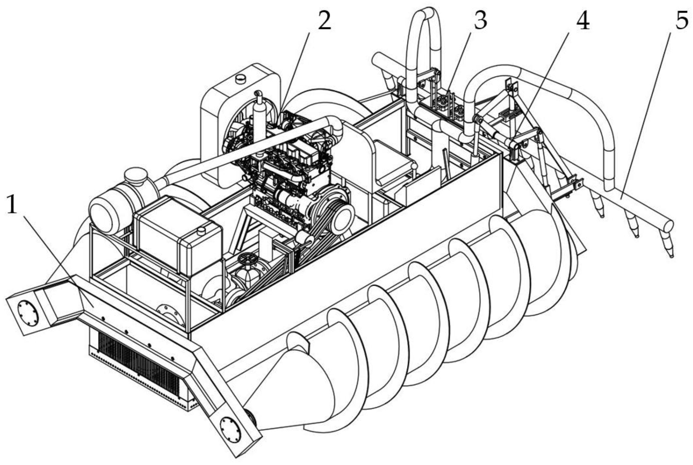
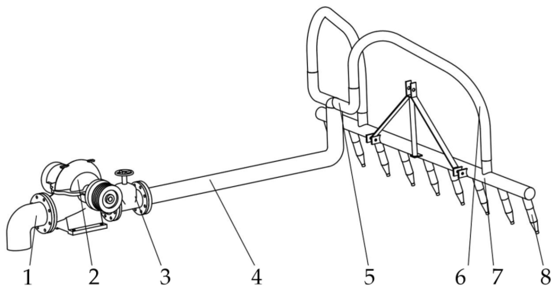
2.1. Structure Design and Operation Principle

The wide-width root digger consists of a twin-screw drive chassis carrying a hydraulic scouring system, the structure of which is shown in Figure 1. The twin-screw drive chassis provides the driving force for the machine. The hydraulic control system controls the rotational speed and direction of rotation of the spiral drums on both sides to enable straight driving and steering. The hydraulic scouring system provides high-pressure water jets to break up and disperse the top layer of soil on the lotus roots. As a result, the lotus root floats upwards under its own buoyancy. Finally, the lotus roots are salvaged out of the water by the workers. The lotus root harvesting operation is complete.
The hydraulic flushing system studied in this paper is an important part of the root digger. It includes the inlet pipe, the pump, the flow regulating valve, the delivery pipe, the distributor and the nozzles. The structure is shown in Figure 2. When the root digger is in operation, the water pump rotates at high speed driven by the engine and pumps water up through the inlet. The water flows through the pipes and out of the nozzles at high speed to create a high-pressure water jet. This water jet impacts and breaks up the soil, causing the lotus roots to rise to the surface and complete the harvesting of the roots.

2.2. Water Pump Selection and Feasibility Analysis

2.2.1. Water Pump Selection

By investigating the actual operation of the root digger, we found that the root digger pump is required to have a sufficiently large flow rate, high head, and reliable working performance. A study showed that the soil firmness at a depth of 300 mm below the root field mud was 0.21–0.92 MPa, and the lotus root extrusion crushing strength was 2.32 MPa [27]. Referring to the 4CWO-3.2 boat type root dredger [8], we aimed for a design with a unit kinetic energy E of 30 m at the nozzle outlet fluid.
E k = 1 2 g a v 2
where v is the average flow rate in the pipe section, m·s−1; a is the kinetic energy correction factor, normally taken as a=1.05; g is the gravitational acceleration, 9.8 m·s−2; Ek is the kinetic energy per unit weight of a body of water, referred to as the unit kinetic energy, m.
From the design target current unit kinetic energy of 30 m, the current velocity is 19.32 m·s−1. Refer to reference [8], compared the flow rate per unit time through the nozzle when the nozzle outlet diameter is 13 mm, 16 mm and 19 mm, and considered the need for adequate water to push the soil away from the flushed soil, we determined the nozzle outlet inner diameter to be 16 mm, so the individual nozzle flow rate is 17.129 m3·h−1. This hydraulic flushing system has 9 nozzles, so the flow rate of the pump should be greater than 154.157 m3·h−1. Compared with the characteristics of various pumps, we finally settled on the 150S78 single-stage double-suction centrifugal water pump, manufactured by Hebei Kreda Co from China. Its performance parameters are rated flow rate 162 m3·h−1 and rated head 78 m.

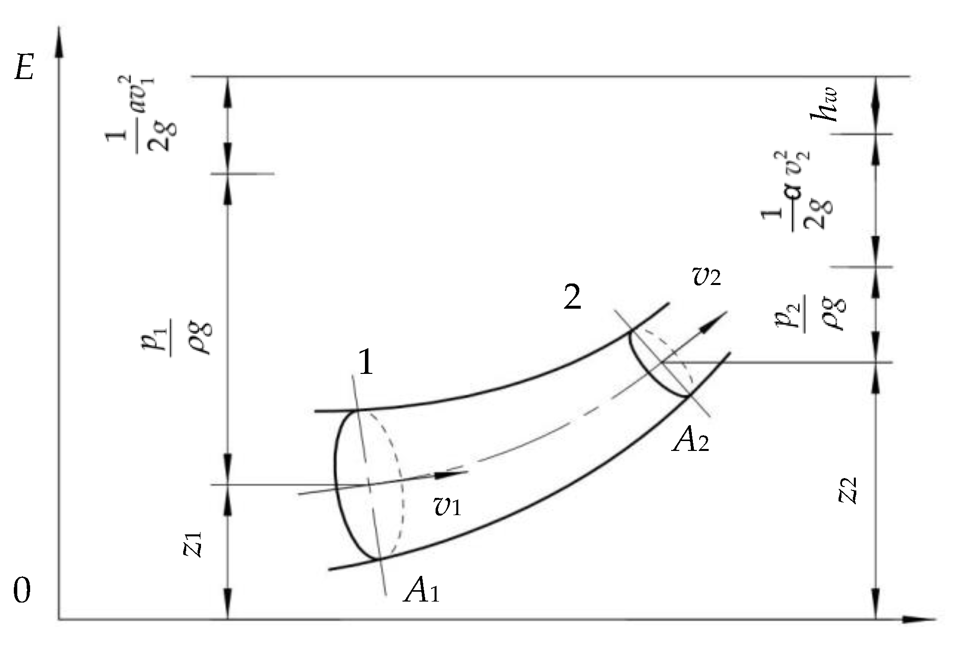
2.2.2. Pipeline Energy Loss Analysis

To ensure that the high-pressure water flow in the hydraulic system has sufficient unit kinetic energy, we accounted for the energy losses in the transmission pipeline to ensure that the pumps could provide sufficient mechanical energy [28].
The energy of water movement includes potential energy, pressure energy and kinetic energy. The relationship between them satisfies the law of conservation of energy and the law of interconversion of energy. According to the Bernoulli energy equation, the energy equation for the steady-state flow of a viscous incompressible fluid is shown in Equation (2) [29]. The water flow energy conversion model is shown in Figure 3.
p 1 ρ g + z 1 + 1 2 g a v 1 2 = p 2 ρ g + z 2 + 1 2 g a v 2 2 + h w
where p1 and p2 are the pressures of the moving water on Section 1 and Section 2 respectively, Pa. z1 and z2 are the height of the location of the centre point of Section 1 and Section 2 respectively, m; v1 and v2 are the average flow velocity at Section 1 and Section 2, respectively, m·s−1; ρ is the density of fluid, kg·m−3.
The terms in the water flow energy Equation (2) have different physical meanings. p ρ g is the pressure energy per unit weight of water, referred to as the unit kinetic energy, m; z is the potential energy per unit weight of water, referred to as the unit potential energy, m; 1 2 g a v 2 is the kinetic energy per unit weight of water, referred to as the unit kinetic energy, m; hw is the energy loss per unit weight of water between the two sections, referred to as the unit energy loss, m.
h w = Σ h f + Σ h j
where ∑hf is the total along-travel unit energy loss, m; ∑hj is the total local unit energy loss, m.

Analysis of Unit Energy Losses along Pipeline

The matching piping components are designed according to the performance and structural parameters of the 150S78 pump.
With reference to the relevant waterway pressure drop theory in Hydraulic Calculation Manual and Principles of Chemical Engineering, the flow pattern of the fluid was determined by the Reynolds number Re and the energy loss along the path hf was calculated [29,30].
If the flow of the fluid is tropospheric:
h f = 32 μ v S d 2 1 ρ g
If the flow of the fluid is turbulent:
h f = λ S d v 2 2 g
where λ is the resistance coefficient; μ is the coefficient of dynamic viscosity, Pa·m; d is the internal diameter of pipe, m; S is the length of pipe, m.
This hydraulic scouring system has energy losses along its entire length, mainly at the main transmission pipe and the metal braided bellows. The pipe is made of new seamless steel pipes. According to reference [30], The flow velocity in the pipe was calculated and the Reynolds number of the fluid was determined, based on which we determined that this was an example of turbulent flow. In addition, the relative surface roughness of the fittings was obtained. Based on the relative roughness of the pipe walls and the Reynolds number of the water flow, the resistance coefficient λ for each fitting that we checked in the literature [30]. Therefore, the energy losses along the journey are shown in Table 1.
The main section of this hydronic system is piped in a parallel layout. According to the law of conservation of energy, the flow rate in the main circuit is equal to the sum of the branches, so that the energy loss per unit of water flow between the point of diversion and the point of merging of parallel branches is calculated for only one branch [31]. The total energy loss along this waterway system is 5.838 m.
Σ h f = 1.507 + 4.331 = 5.838   m

Analysis of Local Unit Energy Losses in Pipelines

The fluid is accompanied by local unit energy losses at components where the pipe diameter or flow direction has changed. The resistance coefficient method is usually used to calculate the local energy loss hj [29].
h j = ζ v 2 2 g
where ζ is the local energy consumption factor.
When there is a sudden change in pipe diameter, the local energy consumption coefficient is calculated according to Equation (7) [29].
ζ = { ( 1 A 1 A 2 ) 2 , Sudden   enlargement   of   pipe   diameter 0.5 ( 1 A 1 A 2 ) , Sudden   reduction   of   pipe   diameter
where A1 is the small diameter flow-through area of the reducer, m2; A2 is the large diameter flow-through area of the reducer, m2.
The value of (A1/A2) is very small where there is a sudden and drastic change in the fittings, so it can be seen from Equation (7) that ζ is taken to be 1 where the diameter of the pipe expands sharply (container inlet) and 0.5 where the diameter of the pipe shrinks sharply (container outlet).
When the pipe diameter is gradually reduced as shown in Figure 4. The energy consumption coefficient is calculated according to Equation (8).
ζ = k 1 k 2
where k1 is the energy consumption coefficient for angle change; k2 is the energy consumption coefficient for changes in the through-flow area. k1 and k2 can be found through Hydraulic Calculation Manual [29].
Based on the geometrical parameters of the fittings, the local unit energy losses were calculated as shown in Table 2.
The total unit energy loss of the system is calculated according to Equation (3).
h m = Σ h f + Σ h j = 17.197   m

2.2.3. Pump Head Accounting

The total mechanical energy required per unit weight of fluid is referred to as unit total mechanical energy. The unit is m.
E = p ρ g + z + 1 2 g a v 2
The nozzle outlet position was considered as zero energy height. The nozzle outlet was at 400 mm underwater and it had a pressure of 4000 Pa. Nozzle outlet flow rate of 24.868 m·s−1 and the kinetic energy correction factor of 1.05. From Equation (9), it can be obtained, through the nozzle outlet cross-section of the unit of fluid has a total unit mechanical energy of 33.538 m.
Considering the pipeline energy losses, the minimum total mechanical energy per unit weight of the fluid to be obtained for this hydraulic system of 50.735 m.
E = 33.538 + 17.197 = 50.735 m
Because the rated head of the selected pump of 78 m is greater than the minimum mechanical energy required per unit weight of fluid in the pipeline, the pump met the requirements of this water scouring system.

2.3. Key Nozzle Parameters Determination Based on CFD Simulation

The nozzle is the most critical part of the hydraulic system design. In this paper, the type of nozzle, the structure of the constriction section and the actual structural parameters of the nozzle were designed by CFD simulation to obtain a nozzle structure with the best scouring performance.

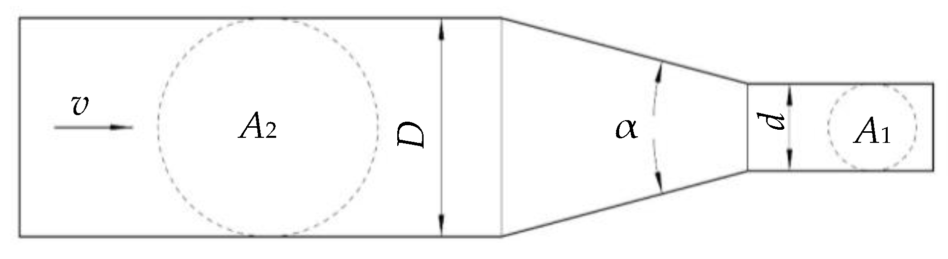
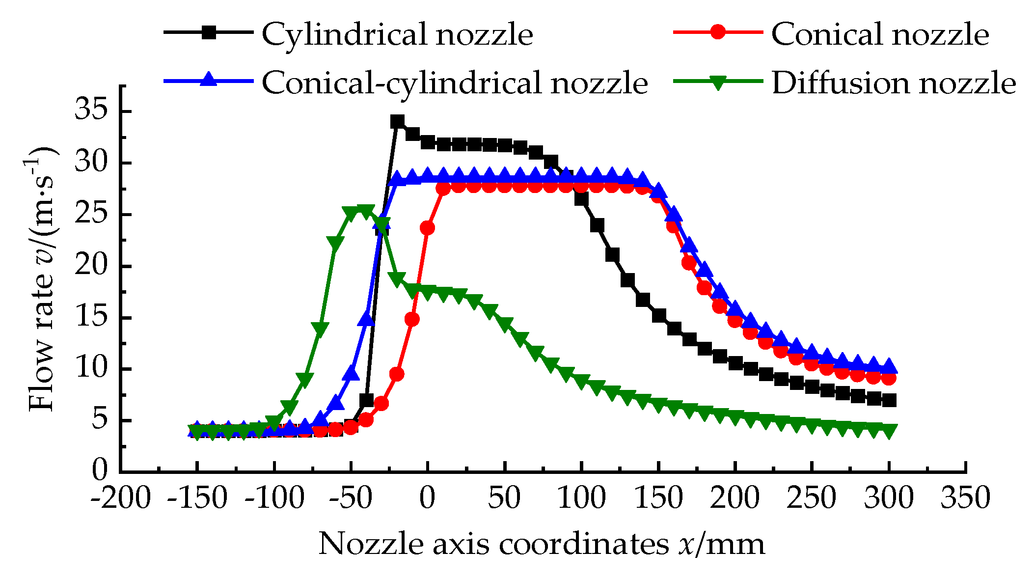
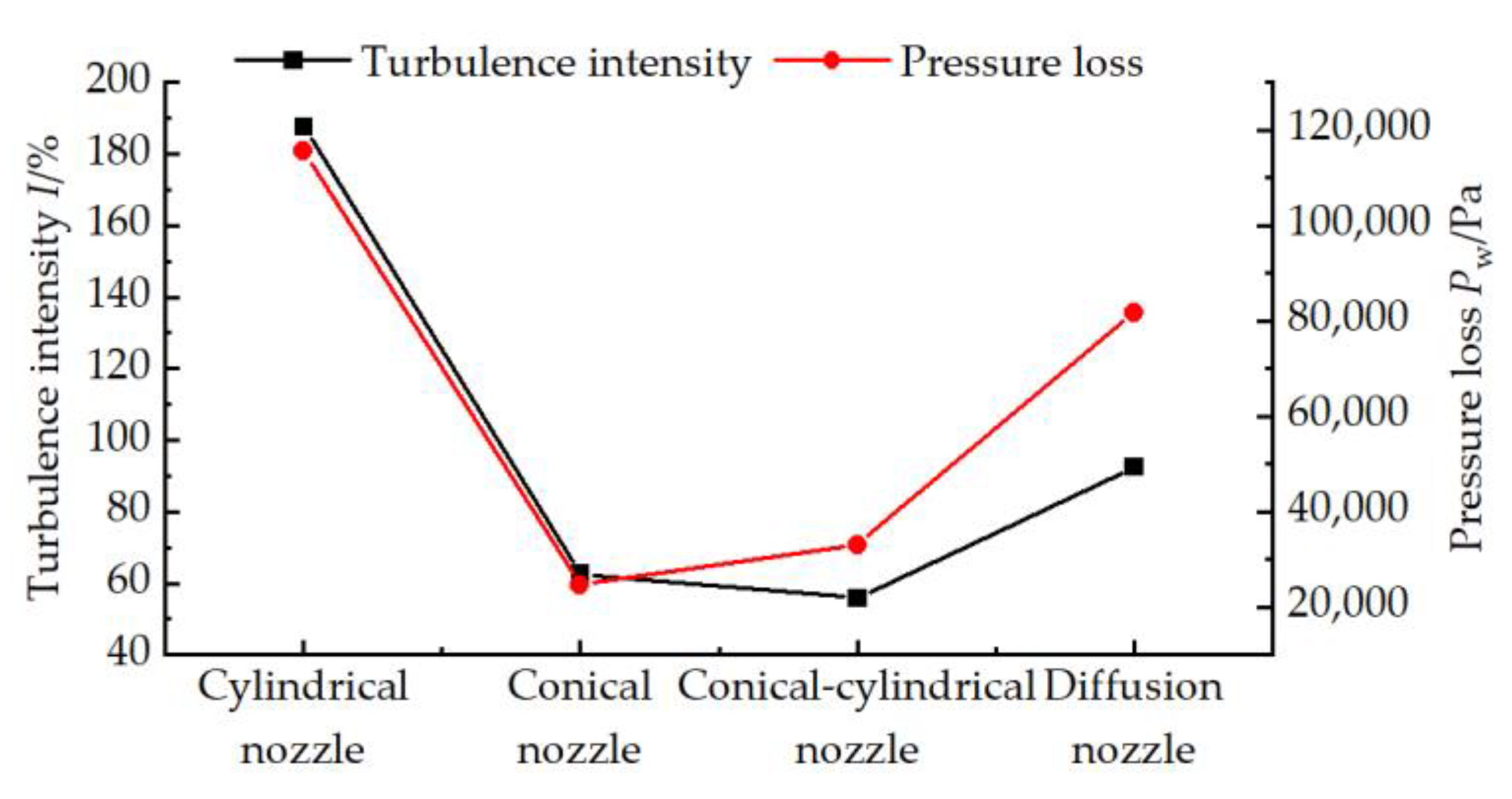
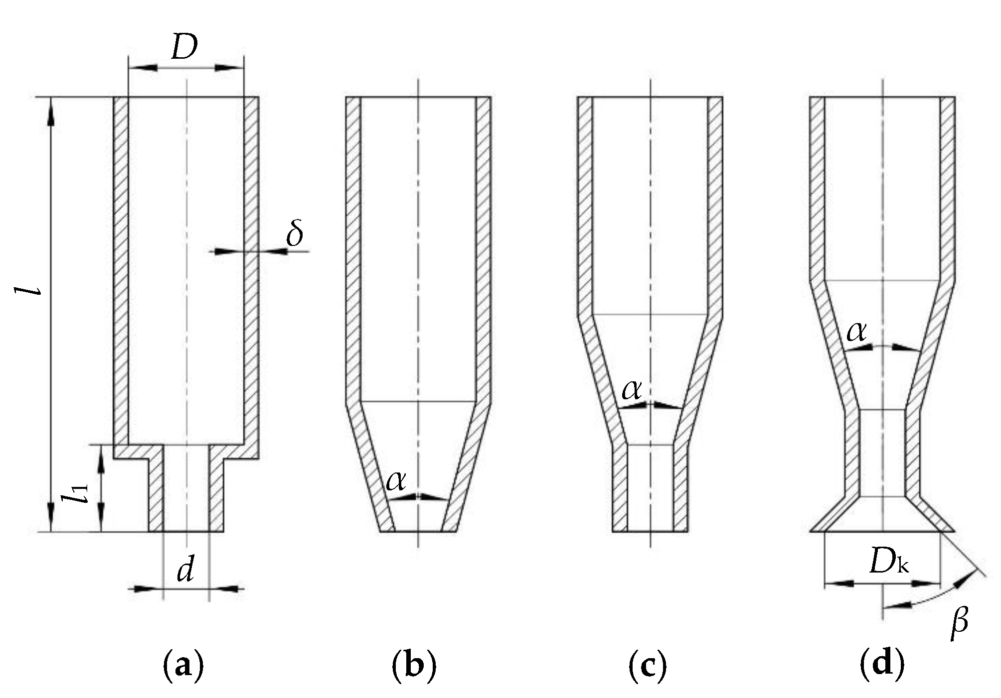
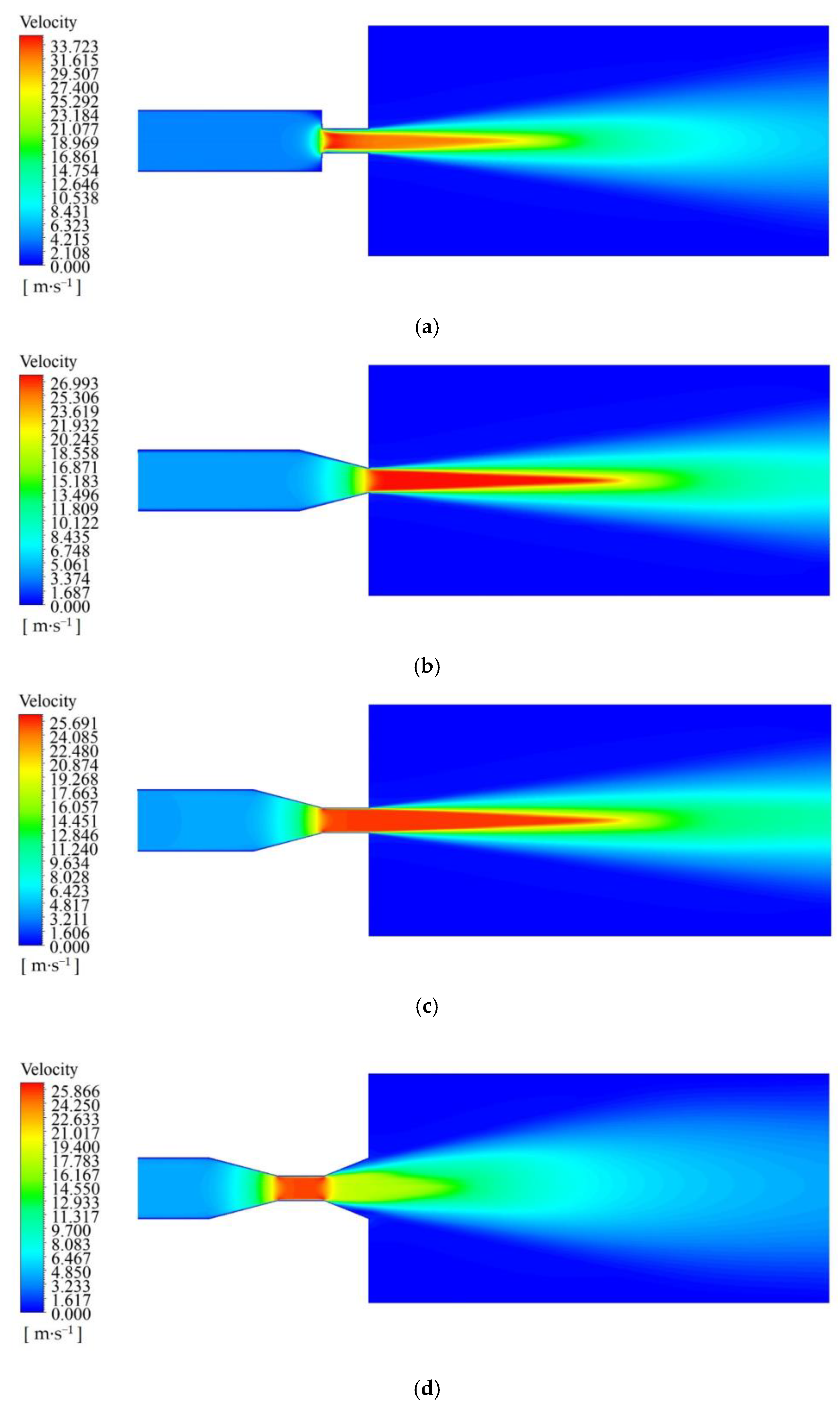
2.3.1. Nozzle Types Comparison

According to the book named “Water Jet Technology and Engineering Application” [28], it is known that there are four common types of nozzles. They are cylindrical nozzles, conical nozzles, conical-cylindrical nozzles and diffusion nozzles. The structure of the four nozzles is shown in Figure 5. With a nozzle outlet diameter of 16 mm as the design target, we determined the nozzle size in the nozzle type comparison test as shown in Table 3.
Assuming that the piping structure and power source remain the same and ignoring the effect of the nozzle structure on the water supply performance of the pump, we conducted a comparative test of the performance of the nozzles.
In all simulation tests, the nozzle inlet fluid mass was set to 5 kg·s−1 and the nozzle outlet was set to pressure type of 4000 Pa. The simulations compared four types of nozzle axial fluid velocity variation, fluid turbulence intensity at the nozzle outlet and pressure loss between the nozzle inlet and outlet sections. The fluid velocity cloud in the nozzle is shown in Figure 6. The variation in fluid velocity at various points along the nozzle axis is shown in Figure 7. The comparison of nozzle scouring performance is shown in Figure 8.
Test results showed that cylindrical and conical-cylindrical nozzles have good jet agglomeration, long isokinetic nuclei and stable jets. Diffusion nozzles with a large jet range but significant energy loss. Conical nozzles and conical-cylindrical nozzles have less turbulence intensity and less pressure loss between the nozzle inlet and outlet sections. Comprehensive analysis of various nozzles to produce the characteristics of the jet, we selected the nozzle type for the conical-cylindrical nozzle.

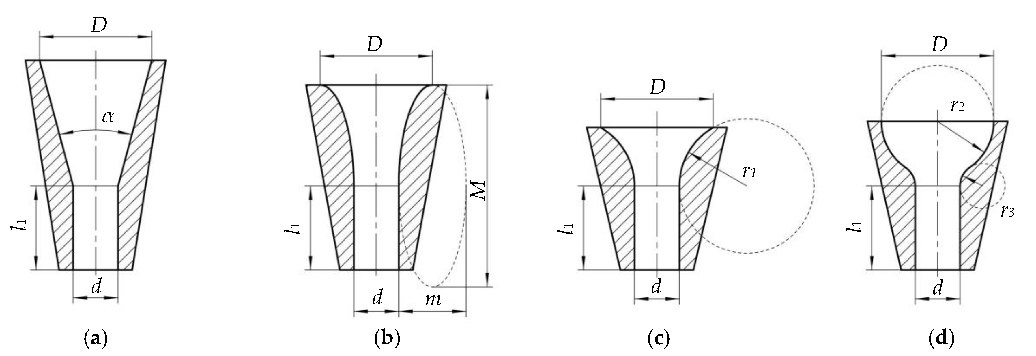
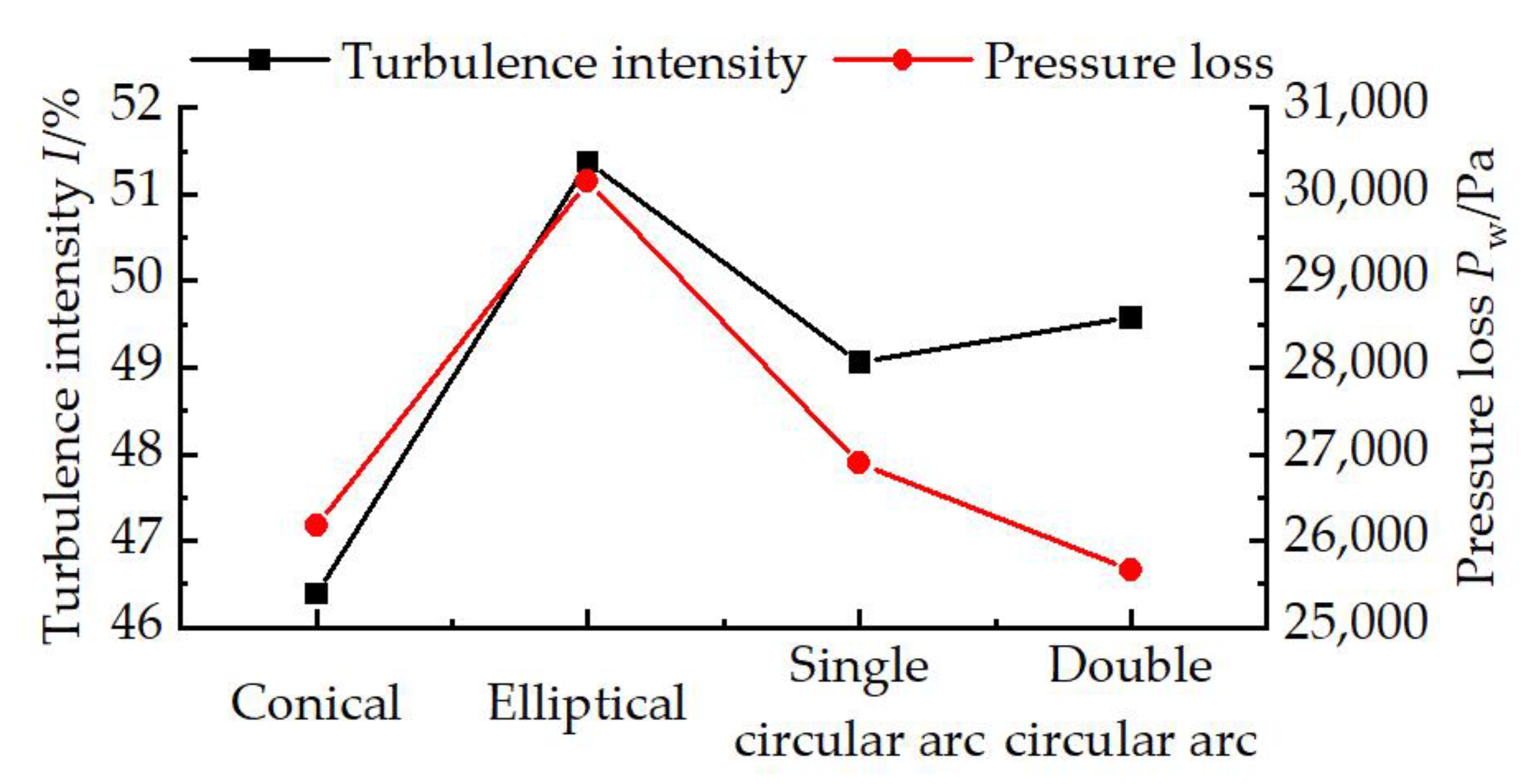
2.3.2. Nozzle Shrinkage Section Construction Comparison

The conical-cylindrical nozzle is a shrinkage type nozzle. To investigate the effect of the contraction section type on the performance of the generated jet, this paper has conducted a simulation comparison analysis of four types of contraction section structures: conical, elliptical, single circular arc and double circular arc [28]. The structure of the nozzle shrinkage section is shown in Figure 9, and the nozzle geometry parameters are related as Equation (10).
{ l 1 = 2 d m = D d M = 3 m r 1 = D d r 2 = D / 2 r 3 = d / 2
The turbulence intensity at the nozzle outlet and the pressure loss between the nozzle inlet and outlet sections for the four nozzle constriction types are shown in Figure 10. The test results show that the conical shrinkage nozzle outlet has the lowest turbulence intensity and better scouring performance.

2.3.3. Conical-Cylindrical Nozzle Structure Parameters Determined

Orthogonal tests were carried out to determine the specific structural parameters of the conical-cylindrical nozzle with the best scouring performance. To minimise experimental errors caused by variations in nozzle length due to changes in nozzle configuration. Using the nozzle structure at a minimum contraction angle of 20° as a reference, the total nozzle length l was determined to be 200 mm. A three-factor, three-level orthogonal test was carried out with the nozzle inlet diameter D, the shrinkage angle α and nozzle outlet straight section length l1 as the test factors. The influence factors of the orthogonal test are shown in Table 4.
The turbulence intensity at the nozzle outlet section I and the pressure loss between the nozzle inlet and outlet sections Pw were used as evaluation indicators. Orthogonal table L9(34) was selected for the orthogonal test. Both range analysis and variance analysis were used to analyse the data from the orthogonal tests. The experimental arrangement and results are shown in Table 5. The results of the range analysis are shown in Table 6. The results of the variance analysis are shown in Table 7.
The range analysis and variance analysis of the test results showed that the order of each factor on the turbulence intensity at the nozzle outlet section I are ranked as l1 > D > α. Among them, nozzle outlet straight section length l1 has an extremely significant effect on the turbulence intensity I, the nozzle inlet diameter D has a significant effect, and the shrinkage angle α has no significant effect. The order of each factor on the pressure loss between the nozzle inlet and outlet sections Pw are ranked as l1 > α > D. Among them, nozzle outlet straight section length l1 has an extremely significant effect on the pressure loss Pw, the shrinkage angle α has a significant effect, and the nozzle inlet diameter D has no significant effect.
The significance of the effect of each test factor on the test index was considered in combination. The best combination of the orthogonal test was D1α2l11. However, it was not in the tests that had been done, and verification tests were carried out to obtain a turbulence intensity at the nozzle outlet section of 51.28%, and a fluid pressure loss between the nozzle inlet and outlet sections of 27,494.34 Pa. The turbulence intensity of this solution is better than that of the tests carried out, and although the pressure loss is not the best in the tests carried out, it is not significantly different from the best results of the tests carried out.
The combined analysis concludes that this option D1α2l11 is the optimal option. Nozzle outlet diameter of 16 mm, nozzle inlet diameter D for 40 mm, shrinkage angle α for 30°, nozzle outlet straight section length l1 for 20 mm, the nozzle has a better flushing performance.

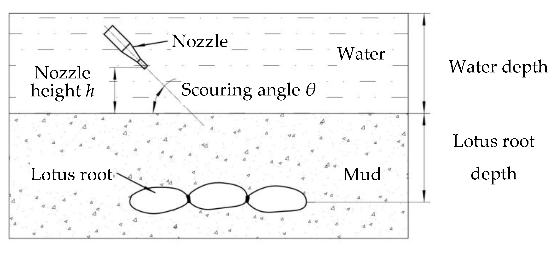
2.4. Method and Material of Hydraulic Scouring System Performance Test

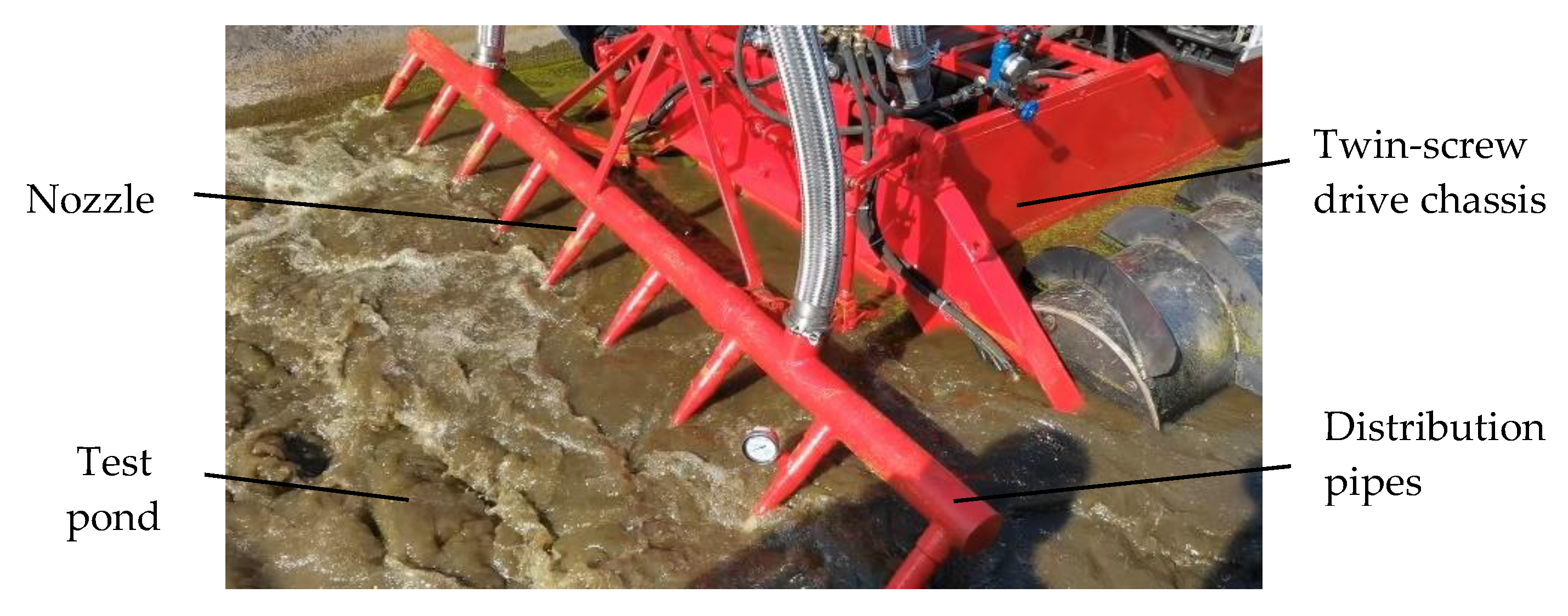
2.4.1. Test Site and Lotus Roots

The tests were carried out in the pond at Hubei Shouxing Machinery Co. The length of this test pond of 20 m and the width of 3 m. The bottom of the pool has a large amount of soil with a total thickness of more than 500 mm and a distance of 400 mm between the surface of the soil and the water surface. The lotus roots used in the trial were freshly harvested intact plants of “E lotus No. 5”.

2.4.2. Verification Test

To verify the results of the simulation tests, the actual flow and pressure of the nozzles were measured for comparison with the simulation tests and to provide a reference for later performance tests of the hydraulic flushing system.
The test with nozzle outlet diameter was carried out of 16 mm, nozzle inlet diameter D of 40 mm, shrinkage angle α of 30°, the nozzle outlet straight section length l1 of 20 mm. The flow and pressure distribution of each nozzle on the manifold was measured and compared to analyse the homogeneity between each nozzle. The actual flow rate of this hydronic system nozzle was measured in terms of the time required to draw a certain volume of water with the flow regulating valve fully open. A pressure gauge was used to measure the actual pressure value at the nozzle inlet.

2.4.3. Single-Factor Test

Referring to the research of Wu et al. [6,10], it is found that the factors affecting the hydraulic flushing performance include nozzle outlet pressure, nozzle flushing angle and nozzle outlet height from the mud surface.
Taking this hydraulic system as the object of study, combined with the results of pre-experiments, we took the nozzle outlet pressure 0.10–0.30 MPa, nozzle scouring angle 30°–90°, nozzle outlet height from the mud surface 0-150 mm as the test factors, and carried out single-factor tests with effective scouring depth as the test indicators.
The purpose of this single factor test was to investigate the influence of each factor on the scouring performance of the hydraulic scouring system and to obtain the optimal range of values for each factor. only one factor was changed for each test group, while the other factors were fixed, as shown in Table 8. The nozzle flushing diagram is shown in Figure 11.

2.4.4. Box–Behnken Centre Combination Design Test

To figure out the relationship between the strength of each test factor on the nozzle scouring performance and the interaction between them, we completed a Box–Behnken central combination design test based on the single factor test. The same as the single-factor test, nozzle outlet pressure, nozzle flush angle and nozzle outlet height from the mud surface were used as test factors and the effective scouring depth was used as the test indicators.
This three-factor, three-level Box–Behnken central combination design trial had 17 sets of trials, each of which was repeated three times, and the average of the three trial results was used as the final test indicators. The Box–Behnken design of factors and levels is shown in Table 9. The protocol for the Box–Behnken central combined design test is shown in Table 10.

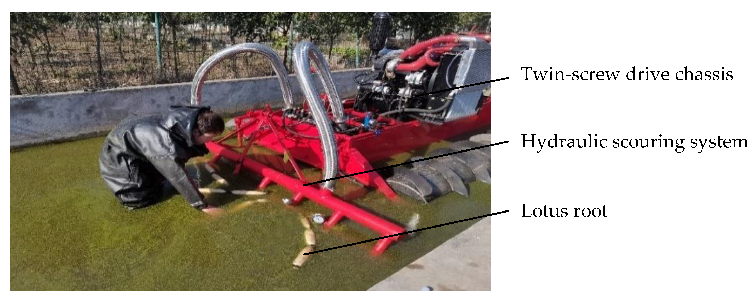
2.5. Lotus Root Harvesting Test

The hydraulic scouring lotus root harvesting tests were completed to verify the working performance of the hydraulic scouring system. In the experiments, the test pond with pre-buried lotus roots were used as experimental root fields. Harvesting tests were then carried out with the hydraulic scouring system studied in this paper. Four freshly harvested intact lotus roots were buried 300 mm below the mud perpendicular to the direction of machine movement as a group. The scouring harvest tests were carried out with the nozzle pressure of 0.30 MPa, the scouring angle of 60° and the nozzle distance from the mud surface of 0 mm. Floatation and damage rates of lotus roots were used as evaluation indicators for the hydrodynamic scouring of lotus root harvesting tests. The test was repeated five times and their average value was taken as the test result. The hydraulic scouring lotus root harvest test is shown in Figure 12.

3. Results and Discussion

3.1. Verification Test Results and Analysis

The verification test showed that the actual total flow rate of the hydraulic system of approximately 152 m3·h−1, with a coefficient of variation of 6.17% from the rated flow rate of the pump of 162 m3·h−1. The flow rates of each nozzle were compared with each other and the average value of the nozzle flow rates was 16.88 m3·h−1. The coefficient of variation of the flow rates between the nozzles of 11.56%. The nozzle near the inlet of the manifold has a higher flow rate and the nozzle in the very middle of the manifold has a lower flow rate. And, the outlet flow rate of the nozzle of approximately 23.33 m·s−1. According to Equation (1), the unit kinetic energy per unit weight of water flow of 27.78 m, and the coefficient of variation between it and the design index unit kinetic energy of 7.41%.
The test obtained the average value of the static pressure of each nozzle of 0.30 MPa, which is close to the nozzle inlet static pressure of 0.34 MPa in the previous simulation test, verifying the reasonableness of the nozzle simulation test results. The coefficient of variation of pressure between nozzles of 12.83%. The distribution pattern was similar to the nozzle flow distribution pattern. The pressure value of each nozzle was greater than 0.25 MPa, and the working width met the design requirements. In addition, compared with the investigation of a single nozzle root digger with a matching pump head of only 20 m, the nozzle outlet energy of this hydraulic system still meets the requirements of lotus root harvesting operations.

3.2. Single-Factor Test Results and Analysis

The results of single-factor tests No. 1 to No. 5 in Table 8 showed that the effective scouring depth tended to rise significantly as the nozzle outlet pressure increased. When the nozzle flushing pressure is less than 0.175 MPa, the nozzle flushing depth is less than 300 mm under the mud of the lotus root growing environment, which didn’t meet the requirements of digging roots. The nozzle outlet pressure operating range is taken to be 0.20–0.30 MPa or even higher where the hydraulic scouring system has good scouring performance.
The results of single-factor tests No. 6 to No. 10 in Table 8 showed that the flushing depth slowly rise as the nozzle flushing angle increased. At scouring angles of less than 60°, backfill is seldom produced in soils that have already been scoured away. The better operating range for the nozzle flush angle was 30°–60°.
The results of single-factor tests No. 11 to No. 14 in Table 8 showed that the scouring depth gradually decreased as the height of the nozzle from the mud surface increased. And, the effective scouring depth decreased faster the farther the nozzle distance is. The better operating range of nozzle height from the mud surface is 0–100 mm.

3.3. Box–Behnken Center Combination Design Test Results and Analysis

3.3.1. Significance Tests and Regression Equations

The data from the Box–Behnken centre combination design tests were subjected to analysis of variance and significance tests as shown in Table 11. The analysis of variance shows that the regression Equation is highly significant and does not fail to fit and that the regression Equation for the test indicator fits the test data well.
Factors X1, X2, X3 has a highly significant effect on the test index, interactions X1X3, X32 has a significant effect on the test index, and other factors do not have a significant effect on the test index. After the factors that did not have a significant effect on the test indicator were removed, the regression Equation (11) between the test indicator and the factor code was obtained:
H = 349.6 + 24.5 X 1 + 15.38 X 2 25.12 X 3 + 5.75 X 1 X 3 5.80 X 3 2
The F-values in Table 11 show that the influence of each factor on the nozzle scouring depth are significant in descending order of X3, X1, X2, X32, X1X3, which means that the interaction of nozzle height from the mud surface, nozzle outlet pressure, nozzle spray angle, nozzle height from the mud surface and nozzle outlet pressure affect the effective scouring depth.

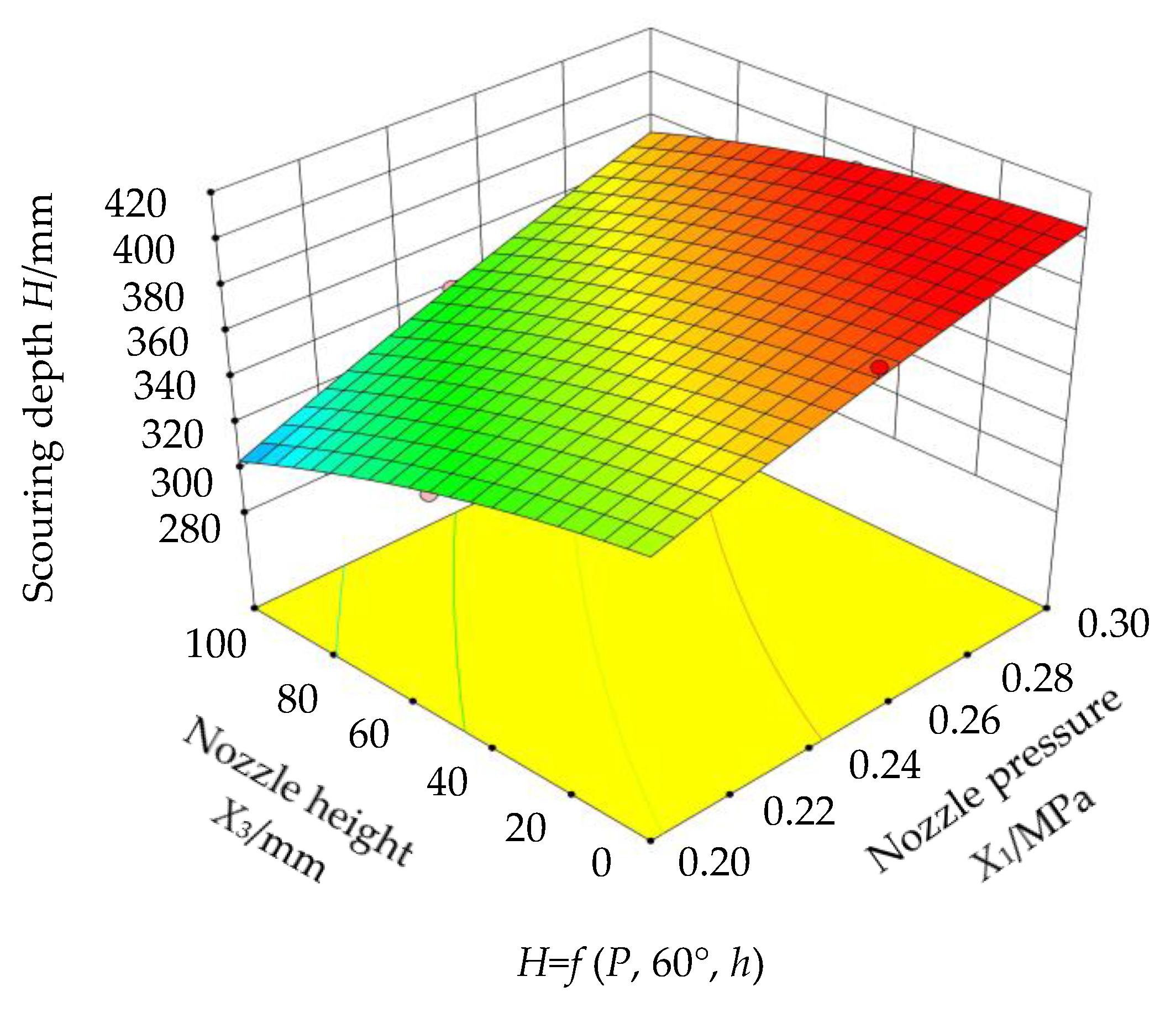
3.3.2. Response Surface Analysis

From the analysis of variance, it is clear that the interaction of nozzle outlet pressure X1 and nozzle angle X3 from the mud surface affects the test index, the other interaction terms have a non-significant effect on the test index. The test factors that interacted significantly are plotted in Figure 13.
Response surface analysis displays that when the nozzle scouring angle of 60°, if the nozzle outlet pressure is fixed, the effective scouring depth decreases as the nozzle distance from the mud surface increased; if the nozzle height from the mud surface is fixed, the effective scouring depth increased as the nozzle outlet pressure increased.
Moreover, when the nozzle outlet pressure of 0.28–0.30 MPa and the nozzle height from the mud surface of 0–20 mm, the effective scouring depth exists at the better value of 395–405 mm.

3.3.3. Parameter Optimisation and Experimental Validation

The model was optimised in Design-Expert 8.0.5 with the optimum effective scour depth as the optimisation objective. The constraints for each factor were shown in Equation (12). Using the Optimisation module, the optimal parameters for nozzle flushing were obtained by solving the regression model with the nozzle outlet pressure of 0.30 MPa, the flushing angle of 60°, the nozzle height of 0 mm from the mud surface, which resulted in a predicted effective flushing depth of 405.45 mm.
{ H = max ( X 1 , X 2 , X 3 ) 0.20 X 1 0.30 30 X 2 60 0 X 3 100
In accordance with the optimised test protocol, the nozzle outlet pressure was maintained at and above 0.30 MPa, the horizontal angle between the nozzle and the mud surface was set at 60° and the nozzle outlet was placed close to the soil surface and the test was repeated three times. The test results showed a scour depth of 395 mm, which was slightly lower than the optimised simulation results. The reason for the analysis is that the strength uniformity of the soil in the test trench has a large influence on the test results. In summary, the flushing effect of this hydraulic system meets the design objectives.

3.4. Lotus Root Harvesting Test Results and Analysis

The effects of the lotus root harvesting trials are recorded in Table 12. The test site is shown in Figure 14.
The test data were analysed, and the results showed that the lotus root float rate was 95% and the coefficient of variation for floatation was 11.8%. The damage rate of lotus roots was 5% and the coefficient of variation of the damage rate was 223.6%. Observed the broken area of the lotus root, which showed small epidermal damage.
The coefficient of variation of the surfacing rate was less than 15%, indicating that the hydraulic scouring system was able to complete the lotus root harvest with smooth operational results. The coefficient of variation of the damage rate was more than 100%, indicating that this hydraulic scouring system was unlikely to cause damage to lotus roots during lotus root harvesting operations. The damage to the skin of the lotus root produced in the test was analysed as a result of a collision with the nozzle swinging from side to side during the floating of the lotus root. However, this form of damage does not affect the main body of the lotus root and its occurrence is relatively low.
As the lotus root was submerged during hydraulic harvesting, it was difficult to obtain a richer operational mechanism for the impact of scouring on the soil by this hydraulic system in this paper. The exact cause of the missed lotus root harvest could not be analysed. Subsequently, a coupled simulation model of the hydraulic scouring system with soil lotus roots and soil will be established to analyse the mechanism of soil particle movement under the impact of water. The causes of lotus root leakage and damage will be analysed to guide the optimisation of the structure and performance parameters of this hydraulic system.

4. Conclusions

(1)
To improve the efficiency of lotus root harvesting operations in large areas, this paper designed a high-flow, wide-width hydraulic scouring system.
(2)
Based on water energy theory and hydraulic scour theory, The pipe components of the hydraulic scouring system were analysed and calculated, and the energy losses in the transmission lines were verified to ensure adequate scouring power.
(3)
Based on fluid simulation tests, the effect of nozzle type, constriction section structure and related structural parameters on nozzle outlet flow velocity, outlet dynamic pressure and turbulence intensity were investigated. The conical-cylindrical nozzle with the inlet diameter of 40 mm, the constriction angle of 30°, the straight cylindrical outlet length of 20 mm and the nozzle outlet diameter of 16 mm had better scour performance.
(4)
Hydraulic scouring performance tests showed that the nozzle outlet pressure of 0.30 MPa, the scouring angle of 60° and the height of the nozzle from the mud surface of 0 mm, the actual effective scouring depth of the verification test was 395 mm, which was basically consistent with the model optimisation prediction results, and all indicators met the design requirements. The lotus root harvesting tests were completed with the lotus root surfacing rate at 90% and the lotus root is hardly damaged, which met the requirements of lotus root harvesting operations.

5. Patents

Two patents have been applied in China for a twin-screw propelled lotus root harvester in this manuscript (Patent No. CN202130203136.3 and Application No. CN202110413636.9).

Author Contributions

Conceptualisation, Y.L., Y.Z. and H.H.; methodology, Y.L.; software, Y.L. and W.L.; validation, Y.L., Y.Z., H.H., M.T., G.Z., L.H. and W.L.; formal analysis, Y.L.; investigation, Y.L., M.T., L.H. and W.L.; resources, Y.L.; data curation, Y.L.; writing—original draft preparation, Y.L.; writing—review and editing, Y.L. and Y.Z.; visualisation, Y.L.; supervision, Y.Z.; project administration, Y.Z.; funding acquisition, Y.Z. and G.Z. All authors have read and agreed to the published version of the manuscript.

Funding

This research was supported by the Fundamental Research Funds for the Central Universities (Program No. 2662020GXPY015) and China Agriculture Research System of MOF and MARA (Grant No. CARS-24-D-02).

Institutional Review Board Statement

Not applicable.

Informed Consent Statement

Not applicable.

Data Availability Statement

The data presented in this study are available on-demand from the first author at ([email protected]).

Acknowledgments

The authors would like to thank their schools and colleges, as well as the funding of the project. All supports and assistance are sincerely appreciated.

Conflicts of Interest

The authors declare no conflict of interest.

References

  1. Li, F.; Zhou, X.X.; Ke, W.D.; Huang, X.F.; Zhu, H.L.; Zhong, L.; Zong, Y.M.; Wu, M.; Peng, J.; Li, S.M.; et al. Research report on lotus industry development in Hubei province. Hubei Agric. Sci. 2020, 59, 101–106, 109. [Google Scholar]
  2. Liu, Y.M.; Ke, W.D.; Huang, X.F. Manual and mechanical mining technology of lotus root. J. Chang. Veg. 2014, 21, 10–15. [Google Scholar]
  3. Zhang, X.Z.; Long, G.; You, Y.Z. The development status, existing problems and countermeasures of lotus root industry in Honghu area. J. Chang. Veg. 2020, 23, 1–3. [Google Scholar]
  4. Liu, M.C.; Mao, D.W.; Wang, Z.H.; Song, Z.H.; Wang, G.R.; Li, F.D. Research Status of Lotus Root Digging Technology and Prospect of Lotus Root Harvesting Technology in Yellow Kiver Delta Region. Agric. Eng. 2018, 8, 1–5. [Google Scholar]
  5. Zhang, Y.H.; Jiang, Z.X. Development of a jet-type lotus root digging machine. Cereal Oils Pro. 1982, 8, 33–38. [Google Scholar]
  6. Wu, H.; Xia, J.F.; Zhang, G.Z.; Wang, P.T.; Lao, S.F.; Zhang, X.M. Design and experiment of spin-jet flow type lotus root digging machine based on EDEM-Fluent. Trans. Chin. Soc. Agric. Eng. 2018, 34, 9–14. [Google Scholar]
  7. Wang, W. Research of 4SWO-1.2 Boat-Type Water Power Lotus Root Digging Machine. Master’s Thesis, Nanjing Agricultural University, Nanjing, China, 2009. [Google Scholar]
  8. Huang, H.D.; Zhang, G.Z.; Xia, J.F.; Zhou, Y.; Xu, Q.C. Development of 4CWO-3.2 ship-type lotus root digger. Hubei Agric. Mech. 2008, 3, 24–25. [Google Scholar]
  9. Gao, X.F.; Hong, Z.Y.; Yao, Y.D. Development of High-power Lotus Root Harvesting Machine. J. Agric. Mech. Res. 2021, 43, 94–98. [Google Scholar]
  10. Feng, C.C.; Zhou, Y.; Tu, M.; Ke, H.B.; Chen, H.; Wu, H.; Jiao, J. Design and experiment of screw-propelled type lotus root digging machine. J. Gansu Agric. Univ. 2020, 55, 191–199. [Google Scholar]
  11. Liu, H.Q.; Wang, Z.W.; Cheng, M.; Xu, W.; Liu, H.J.; Yu, X.C.; Zhi, S.J. Development and Application Status of High-Pressure Water Jet Cutting Technology. Mach. Tool Hydr. 2018, 46, 173–179. [Google Scholar]
  12. Lin, Z.L.; Lu, Q.J.; Yi, X.H.; Cheng, X.M. Development and Application of High Pressure Water Jet Technology. Sci. Technol. Ind. Chin. 2021, 5, 46–47. [Google Scholar]
  13. Borkowski, P.J.; Szada-Borzyszkowski, W. Micronization of Hard Coal with the Use of a High-Pressure Water Jet. Energies 2021, 14, 4745. [Google Scholar] [CrossRef]
  14. Liu, J.L.; Sun, H.; Zhu, Y.J. Fracturing mechanism and crack expansion rule of concrete impacted by high pressure water jet. Mater. Str. 2021, 54, 15. [Google Scholar]
  15. Zhao, P.; Zhang, G.C.; Xu, Y.J.; Wang, R.H.; Zhou, W.D.; Han, L.X.; Zhou, Y. Mechanism and effect of jet parameters on particle waterjet rock breaking. Powd. Technol. 2017, 313, 231–244. [Google Scholar] [CrossRef]
  16. Liu, S.Y.; Li, H.S.; Chang, H.H. Drilling Performance of Rock Drill by High-Pressure Water Jet under Different Configuration Modes. Shock Vibr. 2017, 2017, 14. [Google Scholar] [CrossRef] [Green Version]
  17. Yin, D.Y.; Chen, X.C.; Bao, J.S. Research on Milling Technology of 3D Braided Composites Based on Abrasive Water Jet. J. Mech. Eng. 2021, 57, 273–280. [Google Scholar]
  18. Chen, G.M.; Huang, X. Analysis on Key Technologies of Ship Hull Cleaning Robot Based on High Pressure Water Jet. Fluid Mach. 2019, 47, 56–62. [Google Scholar]
  19. Zhao, Z.F.; Yu, C.Y.; Zhong, J.; Huang, J.H.; Zhang, X. Numerical Simulation on Continuous Non-submerged Water Jet Vibration Cleaning Process for Granular Agricultural Products. Trans. Chin. Soc. Agric. Mach. 2018, 49, 331–337. [Google Scholar]
  20. Wang, J.Z.; Yang, S.H.; Xie, Q.Y.; Yi, J.G. Experiment and operating parameter optimization using water jet technology for scallops shucking processing. Trans. Chin. Soc. Agric. Eng. 2017, 33, 289–294. [Google Scholar]
  21. Wang, L.; Ding, X.M. Experimental investigation of washing vegetables with submerged jets of water. Trans. Chin. Soc. Agric. Eng. 2007, 12, 124–130. [Google Scholar]
  22. Li, Y.Q.; Tian, Y.; Deng, J.Z. Optimization of Jet Pig Nozzle Type for Gas Pipeline Based on CFD. Chin. Pet. Mach. 2021, 49, 126–132. [Google Scholar]
  23. Deng, W.; Zhang, R.; Xu, G.; Li, L.; Tang, Q.; Xu, M. The Influences of the Nozzle Throat Length and the Orifice Grooving Degree on Internal Flow Field for a Multi-Entry Fan Nozzle Based on FLUENT. Engineering 2019, 11, 777–790. [Google Scholar] [CrossRef] [Green Version]
  24. Dong, Z.Z.; Fu, B.W.; Guo, C.; Xi, Y.Q. Simulation Analysis of Flow Field of High Pressure Water Jet Nozzle Based on CFD. Petro Chem. Equip. 2016, 19, 20–23. [Google Scholar]
  25. Wang, X.K.; Xue, Z.L.; Xu, S.R.; Fan, E.D.; Wang, X.; Zhang, C.X. Hydraulic Performance of Negative Pressure Feedback Jet Sprinkler with Double Nozzles. Trans. Chin. Soc. Agric. Mach. 2019, 50, 278–284. [Google Scholar]
  26. Gao, J.M.; Ma, J.L. Design and test of low-frequency Hartmann atomization nozzle with stepped resonance tube. Trans. Chin. Soc. Agric. Eng. 2017, 33, 66–73. [Google Scholar]
  27. Wu, H. Study on Experimental and Working Mechanism of Jetting Spin Type Digging Lotus Root Machine. Ph.D. Thesis, Huazhong Agricultural University, Wu Han, China, 2018. [Google Scholar]
  28. Lei, Y.Y.; Tao, X.Z. Water Jet Technology and Engineering Application; Chemical Industry Press: Beijing, China, 2017; pp. 14–52. [Google Scholar]
  29. Li, W. Hydraulic Calculation Manual; China Water Conservancy and Hydropower Press: Beijing, China, 2006; pp. 3–25. [Google Scholar]
  30. Chen, M.H.; Cong, D.Z.; Fang, T.N.; Qi, M.Z. Principles of Chemical Engineering, 3rd ed.; Chemical Industry Press: Beijing, China, 2006; pp. 4–67. [Google Scholar]
  31. Qin, B.J.; Xia, Y.M. The Differential Pressure Analysis and Calculation of Pipeline Circulation System in Slurry Shield. Hydr. Pneum. Seals 2016, 36, 52–55. [Google Scholar]
Figure 1. Structure of the wide-width root digger. 1. Twin-screw drive chassis 2. Power system 3. Hydraulic control system 4. Oscillating scouring adjustment structure 5. Hydraulic scouring system.
Agriculture 11 01110 g001
Figure 2. Structure of the hydraulic scouring system. 1. Inlet pipe 2. Single-stage double-suction centrifugal water pump 3. Flow control valve 4. Main transmission pipe 5. Reducing Tee 6. Metal braided corrugated pipe 7. Distribution pipe 8. Nozzle.
Agriculture 11 01110 g002
Figure 3. Schematic diagram of the one-dimensional flow energy Equation.
Agriculture 11 01110 g003
Figure 4. Reducer with progressively smaller through the diameter. Note: α is nozzle shrinkage angle, (°); D and d are the inlet and outlet of the nozzle, respectively, mm; v is nozzle section average flow rate, m·s−1.
Agriculture 11 01110 g004
Figure 5. Nozzle structure diagram. (a) Cylindrical nozzle, (b) Conical nozzles, (c) Conical-cylindrical nozzles, (d) Diffusion nozzles. Note: l is the total length of nozzle, mm; l1 is the nozzle outlet straight section length, mm; δ is Nozzle wall thickness, mm; Dk is Diffusion nozzle diffusion outlet diameter, mm; β is Nozzle diffusion angle, (°).
Agriculture 11 01110 g005
Figure 6. Four types of nozzle velocity clouds. (a) Cylindrical nozzle velocity cloud, (b) Conical nozzle velocity cloud, (c) Conical-cylinder nozzle velocity clouds, (d) Diffusion nozzle velocity cloud.
Agriculture 11 01110 g006
Figure 7. Nozzle centre axis fluid velocity diagram.
Agriculture 11 01110 g007
Figure 8. Comparison of nozzle scouring performance.
Agriculture 11 01110 g008
Figure 9. Structure of the nozzle shrinkage section. (a) conical, (b) elliptical, (c) single circular arc, (d) double circular arc. Where the nozzle inlet diameter D of 40 mm, the nozzle outlet diameter d of 16 mm and the nozzle shrinkage angle α of 30°.
Agriculture 11 01110 g009
Figure 10. Comparison of the performance impact of the shrink section.
Agriculture 11 01110 g010
Figure 11. The nozzle flushing diagram.
Agriculture 11 01110 g011
Figure 12. The hydraulic scouring lotus root harvest test.
Agriculture 11 01110 g012
Figure 13. Response surface analysis.
Agriculture 11 01110 g013
Figure 14. Lotus root harvesting test.
Agriculture 11 01110 g014
Table 1. Calculation table of unit energy losses along the pipeline.
PipingDiameter
d/m
Length
S/m
Flow Rate
v/(m·s−1)
Reynolds
Number Re
Fluid FormsResistance
Coefficient λ
Along-Travel
Energy Loss hf/m
Transmission pipe0.1002.005.730573,000Turbulent0.0451.507
Metal braided hose0.0652.006.781440,700Turbulent0.0604.331
Table 2. Calculation table of local unit energy loss.
Name of Pipe FittingsFlow Rate
v/(m·s−1)
Energy Consumption
Coefficient ζ
Local Unit Energy
Losses hj/m
Flow control valves5.7300.2000.335
90° bend DN1005.7300.7501.256
Reducing Tee5.7301.5002.513
90° bend DN656.7810.7501.760
Distribution pipe inlet6.7811.0002.346
Distribution pipe outlet3.9790.5000.404
Nozzle24.8680.0872.745
Total//11.359
Table 3. Nozzle geometry model parameters.
Parameter TypeValues
Nozzle inlet diameter D/mm40
Nozzle diffuser diameter Dk/mm40
Nozzle outlet diameter d/mm16
Total nozzle length l/mm150
Nozzle outlet straight section length l1/mm30
Nozzle shrinkage angle α/(°)30
Nozzle diffusion angle β/(°)45
Nozzle wall thickness δ/mm5
Table 4. Factors and levels of influence of the orthogonal test.
LevelFactors
Nozzle Inlet Diameter D/mmShrinkage Angle α/(°)Nozzle Outlet Straight Section Length l1/mm
1402020
2503030
3604040
Table 5. Orthogonal test results.
Test No.FactorsIndicators
AB CTurbulence Intensity I/%Pressure Loss Pw/Pa
1111151.8529,064.42
2122255.9935,550.07
3133361.3642,680.71
4212363.3943,686.59
5223154.0327,401.07
6231257.4435,916.57
7313257.2236,395.11
8321363.4442,647.41
9332156.1627,348.68
Table 6. Range analysis table.
Indicators AB C
Turbulence
Intensity
𝐼/%
k156.40 57.49 57.58 54.01
k258.29 57.82 58.51 56.88
k358.94 58.32 57.54 62.73
R2.54 0.83 0.97 8.72
Factors orderC>A>B
Pressure
Loss
Pw/Pa
k135,765.0736,382.0435,876.1327,938.06
k235,668.0835,199.5235,528.4535,953.92
k335,463.7435,315.3235,492.3043,004.91
R301.331182.52383.8415,066.85
Factors orderC>B>A
Table 7. Variance analysis table.
IndicatorsVariation SourceSSdfMSFSignificance
Turbulence
Intensity
A10.4525.227.27*
C118.44259.2282.44**
B e } e Δ 1 . 05 1.83 } 2.88 2 2 } 4 0.72
Total131.768
Pressure
Loss
B2,549,65721,274,82812.39*
C340,980,3002170,490,1501657.31**
A e } e Δ 141 , 964 269 , 521 } 411 , 485 2 2 } 4 102,871
Total343,941,4428
Critical value of F-test: F0.05(2,4) = 6.94; F0.01(2,4) = 18.00. * means the factor is significant when α = 0.1, ** means the factor is significant when α = 0.05.
Table 8. Single-factor test plan and results.
Test No.Nozzle Pressure
P/MPa
Scouring Angle
θ/(°)
Nozzle Height
h/mm
Scouring Depth
H/mm
10.10600196
20.15600277
30.20600332
40.25600375
50.30600392
60.30300366
70.30450378
80.30600390
90.30750404
100.30900411
110.30600400
120.306050392
130.3060100372
140.3060150344
Table 9. Factors and levels of Box–Behnken central combination design tests.
LevelNozzle Pressure X1/MPaScouring Angle X2/(°)Nozzle Height X3/mm
+10.3060100
00.254550
−10.20300
Table 10. Box–Behnken central combination design tests plan and results.
Test No.Nozzle Pressure
X1/MPa
Scouring Angle
X2/(°)
Nozzle Height
X3/mm
Scouring Depth
H/mm
10.203050318
20.303050356
30.206050336
40.306050393
50.20450344
60.30450383
70.2045100288
80.3045100350
90.25300362
100.25600389
110.2530100299
120.2560100340
130.254550351
140.254550351
150.254550349
160.254550353
170.254550344
Table 11. Variance analysis table of scouring depth.
Variation SourceSSdfMSFSignificance
Model12,235.1791359.4668.49<0.0001 **
X14802.0014802.00241.91<0.0001 **
X21891.1311891.1395.27<0.0001 **
X35050.1215050.12254.41<0.0001 **
X1X290.25190.254.550.0704
X1X3132.251132.256.660.0364 *
X2X349.00149.002.470.1601
X1227.38127.381.380.2786
X2257.64157.642.900.1321
X32141.641141.647.140.0319 *
Residual138.95719.85
Lack of Fit91.75330.582.590.1900
Pure Error47.20411.80
Total12,374.1216
Note: p ≤ 0.01 (Highly significant, **); p ≤ 0.05 (Significant, *).
Table 12. Test results of lotus root harvesting.
Test No.Number of FloatsFloat Rate/%Number of DamagesDamage Rate /%
137500
24100125
3410000
437500
5410000
Average/90/5
CV/11.8/223.6
Publisher’s Note: MDPI stays neutral with regard to jurisdictional claims in published maps and institutional affiliations.

