Abstract
It is effective to open the bus-coupler circuit breaker in case of a short-circuit fault. A fast vacuum circuit breaker (FVCB) is an ideal bus-coupler circuit breaker due to its high velocity. The objective of this study was to develop and test a 252 kV/2500 A-40 kA multi-break bus-coupler FVCB. The 252 kV FVCB contained 12 FVCB units. Each phase consisted of four FVCB units connected in series. Each FVCB unit had an electromagnetic repulsion mechanism with an average opening velocity reaching 6.5 m/s. Test results showed the opening time was 1.11 ± 0.08 ms. The capacitance of the voltage grading capacitor of each break was determined to be 10 nF. The prototype 252 kV bus-coupler FVCB passed all partial test duties according to the IEC 62271-100: 2008 and IEC 62271-1: 2007 standards, which include an insulation test and a terminal fault test among others. A 252 kV/2500 A-40 kA multi-break bus-coupler FVCB can be used to quickly cut off a short-circuit fault and effectively limit a short-circuit current.
1. Introduction
The rapid growth in electricity consumption and increased interconnection of power grids have resulted in high fault currents. In regions with large-scale energy systems and intensively distributed loads, the fault current reaches or exceeds the withstand capability of the power networks and equipment [1]. As a result, there is considerable interest in developing a fast and effective method to limit fault current.
Whether a short-circuit fault can be removed in time is the most critical factor in the reliability of a power system. Therefore, much research and testing have been done on current-limiting methods and equipment [2,3,4]. In terms of the grid structure, the transmission voltage level can be improved by splitting the lower-level grid into operations, such as multi-bus split operation or segmented operation. This is a very effective and feasible short-circuit current limiting measure, which has been widely used in power systems at home and abroad. Some European countries are studying the use of neutral point ungrounded or neutral point low resistance grounding method, and the network unlooping operation to limit the short-circuit current. However, this measure directly affects the economy and reliability of the system and requires an increase in the reserve capacity of the entire system, so it should be considered unless necessary. Some power grids adopt measures such as series reactors or high impedance transformers. But it will increase the system impedance in the normal mode, resulting in an increase in network loss. As a new type of fault current limiting technology, the fault current limiter can effectively limit the short-circuit capacity of the power grid and ensure the safe and stable operation of the power grid. However, the high cost, complex triggering and control, and large operating losses limit the further development of fault current limiters. So cutting off the parallel bus quickly is the most effective method to limit a fault current at present. Figure 1 shows the process of isolating a short-circuit fault by breaking a busbar circuit breaker. When the power system is in normal operation, Bus 1 and Bus 2 are connected in series through a bus-coupler circuit breaker. Once a short-circuit fault occurs, both power sources S1 and S2 contribute to a high-amplitude short-circuit current. Next, when the bus-coupler circuit breaker is disconnected, the fault current is limited to the fault side. This not only narrows the fault scope but also reduces the amplitude of the short-circuit current. The speed of the circuit breaker determines the limiting effect on the fault current. However, most of the existing SF6 or vacuum breakers use permanent magnet operating mechanisms, spring operating mechanisms, or hydraulic operating mechanisms. The traditional circuit breaker has the characteristics of a large inrush current and long opening time, for tens of milliseconds. This negatively affects the rapid removal of short-circuit faults. In addition, the multi-break voltage equalization problem of high-voltage vacuum circuit breakers has not been solved well at present. Therefore, in order to effectively limit the short-circuit current, it is very necessary to develop a high-voltage vacuum circuit breaker with a fast opening velocity and low dispersion.
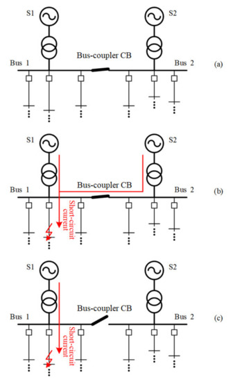
Figure 1.
Method of limiting current by disconnecting parallel buses: (a) power networks in a normal working state; (b) short-circuit current provided by both power sources S1 and S2 in a case of short-circuit fault; (c) short-circuit current is limited by disconnecting two bus-bars through the bus-coupler CB.
The fast vacuum circuit breaker (FVCB) is operated by an electromagnetic repulsion mechanism. It has a shorter opening and closing time, so it is an ideal choice for breaking fault current The electromagnetic repulsion mechanism was first proposed in the 1960s [5]. It consists of three parts: the closing coil, the opening coil, and the repulsion disk. When the charging capacitor in series with the coil discharges, the repulsion disk induces eddy currents through the current in the driving coil. Then, the repulsive force generated by the eddy currents drives the repulsion disk to move up and down quickly, thus completing the opening and closing operation of the FVCB within a few milliseconds. The electromagnetic repulsion actuator is connected with the vacuum arcing chamber by an insulating tie rod. The bus-coupler FVCB combined with a fast relay system for identifying the short-circuit can quickly eliminate the short-circuit, and significantly limit the fault currents contributed by other buses. Although the FVCB is widely used in DC circuits [6,7,8,9], it also performs well in AC circuits [10]. With a higher opening speed and shorter opening time, the FVCB will be the best choice for a bus-coupler circuit breaker in the future.
In this study, a 252 kV/2500A-40 kA multi-break bus-coupler FVCB was proposed and designed. A 252 kV bus-coupler FVCB prototype was built that consisted of four units. The four units in each phase of this FVCB can be opened synchronously. We also optimized the vacuum interrupter and electromagnetic repulsion actuator of the prototype. We have solved the problem of selecting the equalizing capacitor of the multi-break vacuum circuit breaker and improved the insulation recovery performance and breaking capacity of the circuit breaker. The FVCB unit passed mechanical characteristic tests, and the results showed its average opening velocity and opening time were 6.5 m/s and 1.1 ms ± 0.1 ms, respectively. Furthermore, the 252 kV FVCB passed a series of type tests, including a dielectric test, a short-time withstand current test, a peak withstand current test, and a terminal fault test. It turns out that the 252 kV FVCB has great potential to improve the characteristics of a power system.
2. Development of the 252 kV Bus-Coupler FVCB
2.1. Prototype of the 252 kV/2500 A-40 kA Bus-Coupler FVCB
Each of the four breaking units in each phase of the 252 kV/2500 A-40 kA consists of a 40.5 kV FVCB. Figure 2a shows the topology and structure of each breaking unit. For ease of installation, two FVCB units are combined into one FVCB module. Each FVCB unit is connected in parallel to a 10 nF grading capacitor and a 5 Ω damping resistor. The grading capacitor balances the voltage across the circuit. The damping resistor limits the short-circuit current. When the FVCB closes at full voltage, the presence of damping resistance prevents the grading capacitance from being short-circuited directly. Otherwise, the grading capacitor will be burned. Moreover, when the reignition occurs while the FVCB is in operation, the discharge of the grading capacitor may hinder the dielectric recovery in the contact gap. This is not conducive to the success of the breaker. The damping resistance can limit the discharge current and thus contribute to the dielectric recovery.
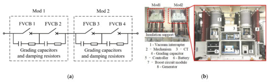
Figure 2.
Single-phase prototype of the 252 kV/2500 A-40 kA bus-coupler FVCB: (a) topology; (b) structure.
Figure 2b shows the overall structural design of the 252 kV FVCB. The FVCB modules are mounted on floating platforms supported by insulators. Each module consists of eight parts: a vacuum interrupter (VI), an electromagnetic repulsion actuator, a current transformer, grading capacitors, and damping resistors, a battery bank, a controller, a generator, and a boost circuit module. For FVCBs, the moving mass of the mechanism plays an important role in the average opening velocity. The FVCB mechanism is more reliable when the moving mass is smaller, and the average opening velocity is faster. Generally, the vacuum interrupter is connected with the electromagnetic repulsion actuator by an insulating rod, which accounts for one-third of the moving mass of the whole actuator. To reduce the moving mass, the floating ground is designed to replace the insulating rod as Figure 2b shows.
Table 1 shows the related technical parameters. The rated voltage is 252 kV. The rated current, the rated short-circuit breaking current and the rated peak withstand current are 2500A, 40kA and 100kA respectively. The rated short-circuit fault duration is set to 0.5 ms because the FVCB will automatically cut off the fault within 20 ms after this occurs. The rated power frequency withstand voltage and the rated lighting impulse withstand voltage are set as 460 kV and 1050 kV, respectively.

Table 1.
Related technical parameters of the 252 kV FVCB.
2.2. Vacuum Interrupters Used in Each Breaking Unit
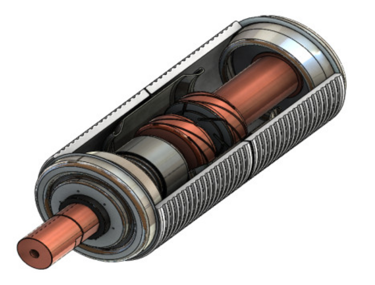
Figure 3 shows the internal structure of the vacuum interrupter in the FVCB unit. The vacuum interrupter adopts cup-type axial magnetic field contacts. The contact diameter is 80 mm. The contact material is Cu50Cr50. The contact pressure of the closing position is 1800 N and is provided by the contact spring. A current of 1 kA can excite an electromagnetic field of 2.6 mT when the circuit breaker is in operation. The distance between contacts in the fully open state is 20 mm. This meets the requirement that the opening time is less than 3 ms for a 40 kA short-circuit current.

Figure 3.
Vacuum interrupter.
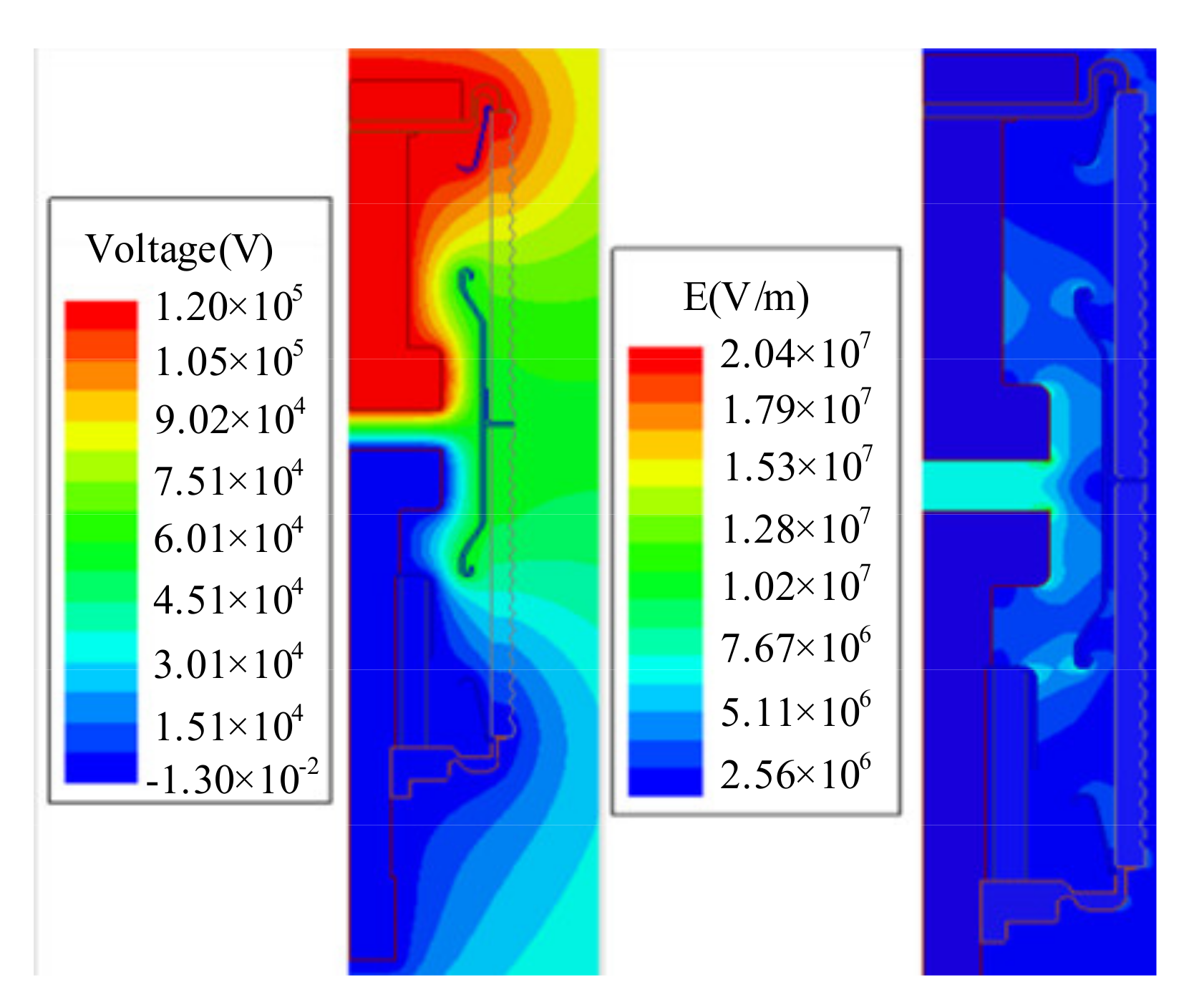
To optimize the vacuum interrupter, we simulated and analyzed the voltage distribution and electric field distribution of the FVCB unit, as shown in Figure 4. The results in Table 2 show that the electric field intensity is highest at the chamfers of the movable contact and the stationary contact, reaching 18.90 kV/mm and 20.00 kV/mm, respectively, during the operation of the circuit breaker.

Figure 4.
Voltage and electric field distributions of the FVCB.
Table 2.
Maximum electric field intensity for each part of the vacuum interrupter.
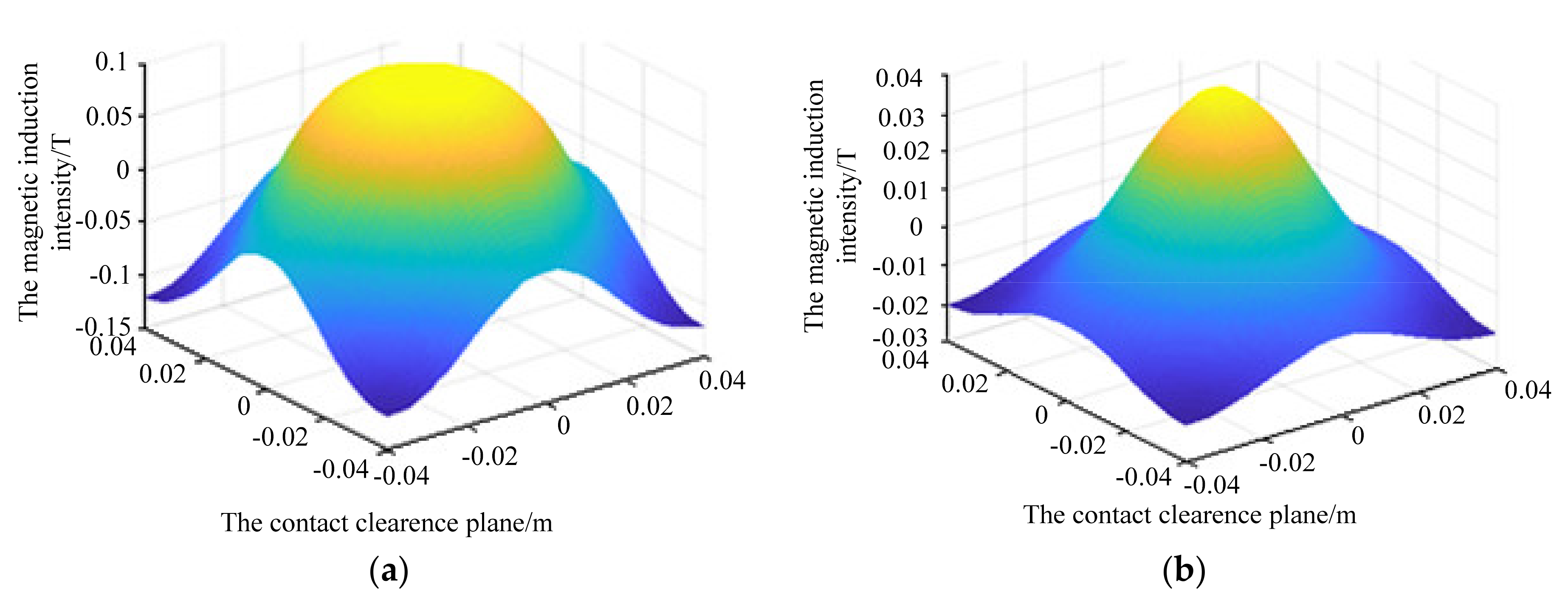
An excessive electric field leads to easy reignition, which is not conducive to the effective operation of the FVCB. Therefore, four different groups of contact chamfers were set up from 0.5 mm to 3 mm for the experiment, and the results are shown in Table 3. By comparing the maximum field intensities of the movable and stationary contacts with different chamfers, we determined the fillet of the contact peripheral to be 3 mm. The maximum field intensity of the contacts is the lowest at this value. Figure 5 shows the magnetic induction intensity distribution of the contact center clearance plane at the peak of the short-circuit current and the zero-crossing point. The length of the vacuum interrupter is 460 mm, and the short-time PF withstand voltage is 115 kV for 1 min.
Table 3.
Maximum electric field intensity of the movable and stationary contacts with different chamfers.

Figure 5.
Magnetic induction intensity distribution of the contact center clearance plane. (a) at the peak of the short-circuit current and (b) at the zero-crossing point.
2.3. Optimization of the Electromagnetic Repulsion Actuator
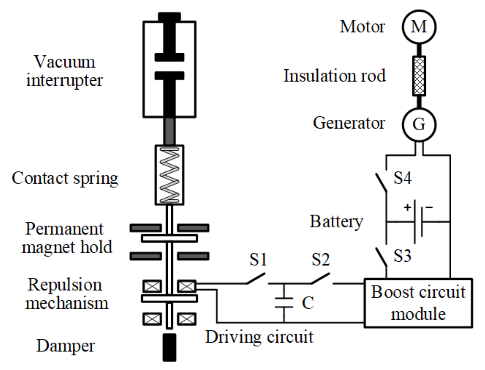
The electromagnetic repulsion actuator consists of a closing coil, an opening coil, and a metal repulsive disk, as shown in Figure 6. The two driving coils are charged by an accumulating capacitor in series with them. The detailed charging circuit is shown in Figure 7. For example, when the FVCB unit performs an opening operation, switch S1 closes, and the accumulator capacitor C charges the opening coil. Then the repulsive force is induced between the opening coil and the repulsive force disk, and the metal plate is pushed downward to complete the opening operation. At the end of the process, the damper increases the resistance and reduces the speed of the metal plate to prevent the actuator from being damaged by a large impact force.
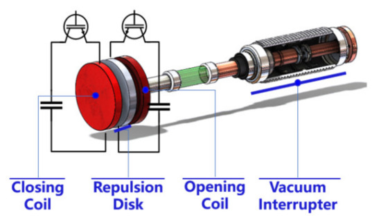
Figure 6.
Electromagnetic repulsion mechanism.
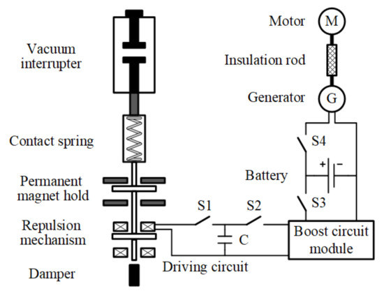
Figure 7.
Charging circuit of the electromagnetic repulsion actuator.
Because the FVCB module does not make contact with the ground directly, its power supply becomes trouble. Therefore, a DC generator is installed on the floating platform. The generator and the motor on the ground are connected by an insulating rod. The electric energy is generated by the motor and transmitted to the generator through the insulating rod. The high-capacity battery bank is charged by the DC generator, then transmits electricity to the FVCB controller and the accumulating capacitors in series with the two driving coils through a DC/DC boost module. This can prevent the motor and the DC generator from startup and shutdown frequently.
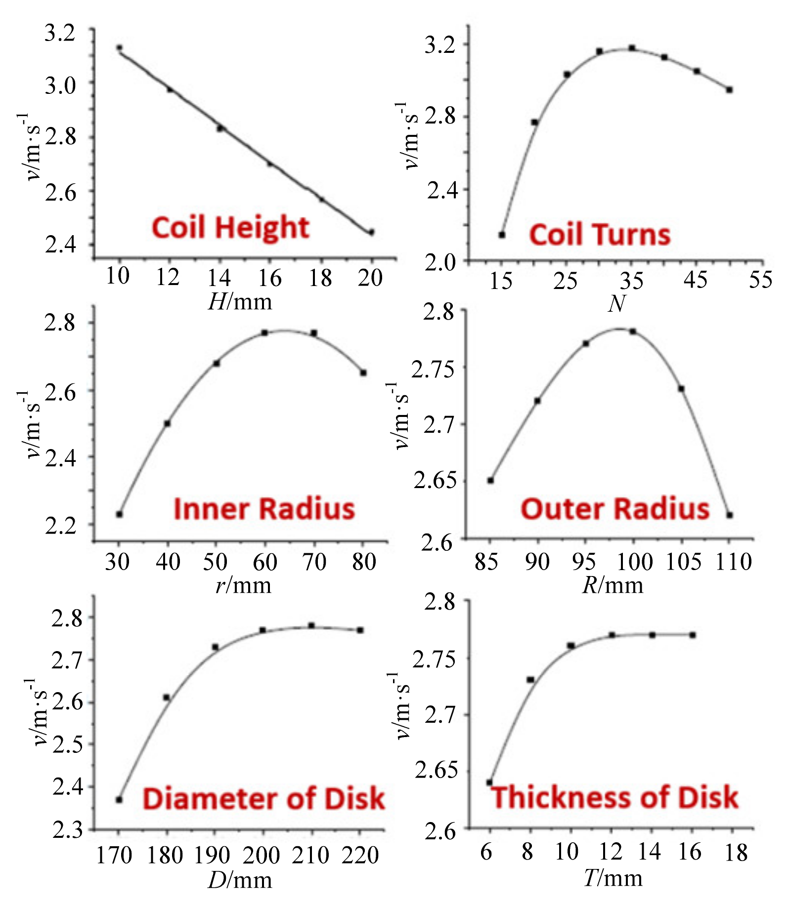
The circuit breaker adopting the electromagnetic repulsion mechanism has a faster opening velocity. The structural parameters of the Thomson coil and repulsion disk significantly influence the opening velocity of the FVCB. The parameters are the height H, the inner radius r, the outer radius R, the number of turns N of the coil structure, and the diameter D and thickness T of the repulsion disk. This study explored the effects of these parameters to optimize the electromagnetic repulsion actuator. An orthogonal experimental design was adopted to analyze the significance of each parameter to opening velocity, and the results are shown in Figure 8. The velocity decreases with increasing coil height. Therefore, a small coil height better optimizes the actuator. Certain values of the inner radius, outer radius, and number of turns of the coil maximize the velocity. Meanwhile, the velocity increases as the diameter and thickness of the repulsion disk increase.
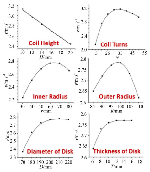
Figure 8.
Influence of impact factors on opening velocity.
By comparing and analyzing the experimental results, we determined the order of significance of each parameter to opening velocity to be: discharging capacitance C > number of coil turns N > charging voltage U > coil height H > disk diameter D > air gap δ > disk thickness T > coil outer radius R > coil inner radius r. According to these results, this study selected the most appropriate parameter values to obtain the fastest velocity. Table 4 shows the parameters of the optimized electromagnetic repulsion actuator.
Table 4.
Parameters of the optimized electromagnetic repulsion actuator.
The optimization of the electromagnetic repulsion mechanism aims at minimizing the storage capacity of the opening capacitor. The optimized capacitance and charging voltage are determined to be 15 mF and 650 V, respectively. The average opening velocity from the contact initial position to a contact displacement of 10 mm is 6.5 m/s.
A simulation and experiment were carried out on the optimized breaking unit, and the opening travel curve of each breaking unit was obtained as shown in Figure 9. The optimized simulation results fit well with the experimental results.
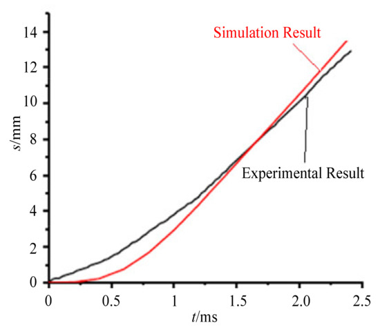
Figure 9.
Opening travel curve.
2.4. Mechanical Characteristic of the 252 kV FVCB
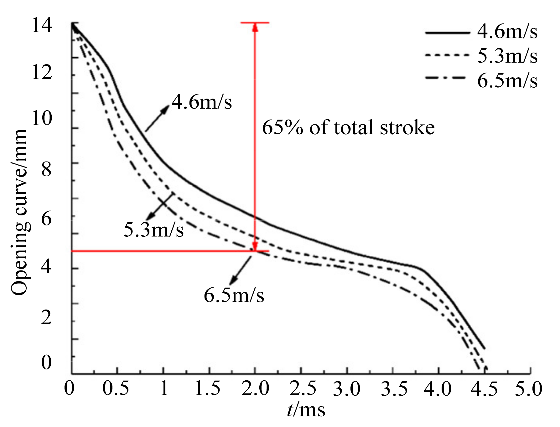
A mechanical characteristic test was performed on each breaking unit to determine the opening travel curve and the opening time. The average opening velocity of the breaking unit was defined as the average opening velocity of the first 65% of the total stroke. The average opening velocity of the fast repulsion actuator increases with the pre-charge voltage of the driving capacitor. In the experiment, the precharge voltage was set as 1 kV, 1.1 kV, and 1.2 kV, and the corresponding average opening velocities were 4.6 m/s, 5.3 m/s, and 6.5 m/s. Figure 10 shows the opening curves of the FVCB under several conditions. The FVCB unit completed the whole stroke within 4.5 ms. It has a shorter opening time and a faster opening velocity than traditional circuit breakers. By comparing the test results, it is finally determined that the opening voltage of the electromagnetic repulsion mechanism is 1200 V.

Figure 10.
Opening curve of the FVCB.
The synchrony between each break is the most important to improve interruption capability for a multi-break FVCB. The 252 kV FVCB prototype developed in this paper contains twelve breaks. The opening time and the synchronicity of each FVCB unit was measured before and after the mechanical endurance test. Figure 11 shows the test results. The opening time of the prototype was 1.11 ± 0.08 ms before the mechanical endurance test and 1.15 ± 0.12 ms after 2000 operation cycles.
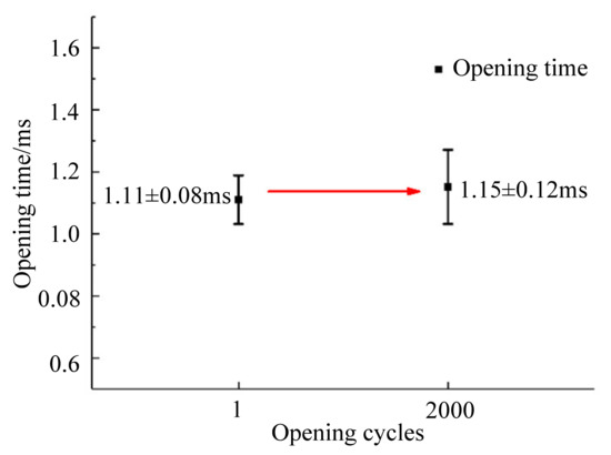
Figure 11.
Opening time and synchronicity of all 12 FVCBs.
Therefore, the 252 kV FVCB prototype shows both a shorter opening time and better synchronization. It is very suitable as a bus-coupler circuit breaker.
2.5. Capacitance of the Voltage Grading Capacitors
To achieve a high insulation performance, voltage grading capacitors are required at each break. Each phase of the 252 kV FVCB consists of four breaks. Its equivalent circuit is shown in Figure 12. The AC power supply was set to 50 Hz/252 kV. The quantities C1, C2, C3, and C4 represent the capacitances between the moving static and the contact when the breakers are open. C10, C20, C30, and C40 represent the stray capacitances of the FVCB unit. Cjy are the voltage grading capacitors, which are connected in parallel to each break. The voltage grading capacitor at each break is the same.
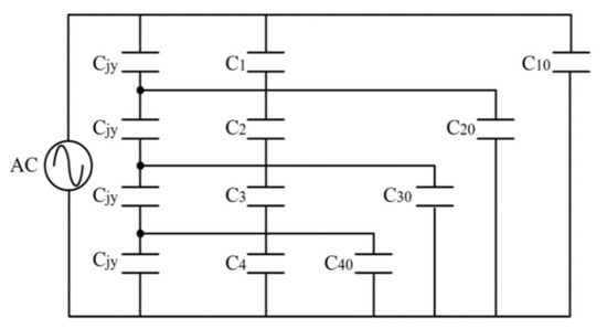
Figure 12.
Equivalent circuit.
The voltage grading capacitors chosen for simulation had capacitances ranging from 100 pF to 40,000 pF. The experiment used 20 combinations of different voltage grading capacitors. The results shown in Figure 13 indicate the equalizing effect improves as the capacitance of the voltage grading capacitors increases. However, when this capacitance increases to a certain level, the improvement in equalizing becomes less significant. A higher capacitance leads to easy intrinsic recovery after the backarc clearance breakdown. Therefore, we determined the capacitance of the voltage grading capacitor of each break to be 10 nF.
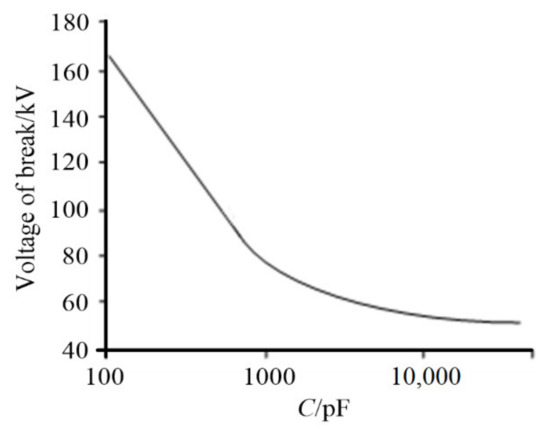
Figure 13.
Equalizing effect of different voltage grading capacitors.
3. Tests of the 252 kV/2500 A-40 kA Bus-Coupler FVCB
Tests of the 252 kV/2500 A-40 kA bus-coupler FVCB were carried out referring to the IEC 62271-100: 2008 and IEC 62271-1: 2007 standards. The tests included a dielectric test, terminal fault test, short-time withstand current, and peak withstand current test, temperature rising test, mechanical endurance test, immunity characteristics test, field test, and short-circuit current-limiting capability.
3.1. Dielectric Test
In the lightning impulse withstand test, standard voltage impulses with a peak of 1050 kV were applied 15 times consecutively with both polarities. In the actual experiment, the amplitude tolerance of the lightning impulse voltage did not exceed 3%. There was no observed destructive partial discharge on the external or inner insulation during the test.
The short-time power frequency withstand test on the FVCB was carried out in phase-to-earth mode with a voltage stress of 460 kV. A single-phase voltage regulator provided a power frequency voltage lasting 1 min. The actual stressed voltage was 460.2 kV with a tolerance of less than 1%. There was still no observed destructive partial discharge on the external or inner insulation during the test.
A dielectric test of the auxiliary and control circuits on the 252 kV FVCB was also carried out in two different positions. A 2 kV voltage was applied between the auxiliary and control circuits and the outer frame of the test FVCB and was maintained for 1 min in case 1. In case 2, 2 kV was applied between each part of the auxiliary and control circuits. There was no disruptive discharge at either of the two test positions.
The dielectric test verified that the 252 kV FVCB could withstand a lightning impulse voltage of 1050 kV and a short-time power frequency voltage of 460 kV. The auxiliary and control circuits also met the requirement of the dielectric test.
3.2. Terminal Fault Test Duties T100s and T60
Terminal fault means that the short-circuit fault occurs directly at the terminal of the circuit breakers. The terminal fault test has the largest fault current compared with other interruption tests. The terminal fault test on the 252 kV FVCB was carried with a synthetic test circuit, in which the generator provided the short-circuit current, and the pre-charged capacitor provided the transient recovery voltage. A 40 kA T100a test duty was carried out two times. and a 40 kA T60 test duty was carried out once. A 50 kA T100a test duty was also carried out on the FVCB. The opening and closing times were 1.19 ms and 13.9 ms, respectively. All the test results are shown in Table 5. The 252 kV FVCB passed all the terminal fault tests. The waveforms of the 50 kA T100a test duty are shown in Figure 14. The test verified that the 252 kV FVCB had a short-circuit current-interrupting capability of 40 kA.
Table 5.
Results of the terminal fault test.
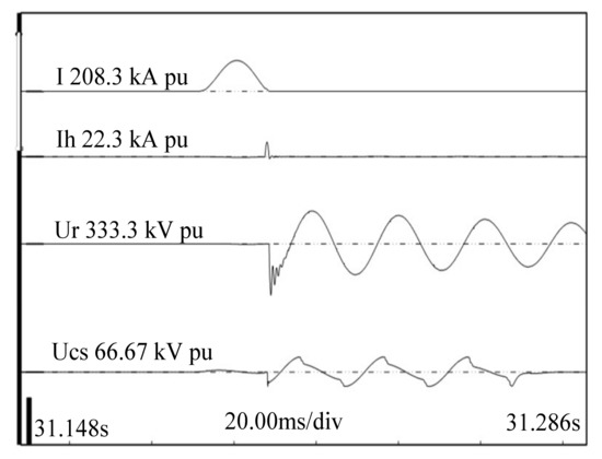
Figure 14.
Terminal fault test waveforms for the 50 kA T100a test.
3.3. Short-Time Withstand Current and Peak Withstand Current Test
The short-time and peak withstand current test on the prototype was performed with a current of 40.8 kA (RMS) lasting 518 ms. The first peak of the test current was 101 kA, and the thermal equivalent was 538 ms. The resistances before and after the test were 119.4 μΩ and 117.0 μΩ, respectively. No arc spraying or contact separation was observed during the test. The FVCB prototype could be open freely on the first attempt after the test.
The test verified that the 252 kV FVCB prototype could withstand a short-time current of 40 kA and a peak current of 100 kA.
3.4. Temperature Rising Test
In the temperature rising test, the maximum temperature was 57.5 K, which appeared at the silver bolted connection at the stationary terminal of the vacuum interrupter. In general, the maximum temperature rise did not exceed the maximum permissible temperature rise of 75 K. The measured resistances before and after the test were 126.5 μΩ and 127.7 μΩ, respectively. Their error was less than 3%. The test verified that the 252 kV FVCB could withstand high temperatures during operation.
3.5. Mechanical Endurance Test
The mechanical endurance test was performed with a 40.5 kV prototype. The opening time was 1.1 ms both before and after the test, and the closing time was 12.7 ms before the test and 13.0 ms after the test. The operating sequence was O-60s-C-60s. The first cycle was set to run 2000 times. Both the closing and opening voltages were 15 V (DC). The resistance of the 40.5 kV prototype changed from 17.4 μΩ before the test to 17.3 μΩ after the test. The 40.5 kV prototype passed the mechanical endurance test.
3.6. Immunity Characteristic Test
The series immunity characteristics test was performed to verify the stability of the control unit of the 252 kV FVCB. The test duties included an electrical fast transient/burst immunity test, a voltage dip, short interruptions, a voltage variation immunity test, a conducted emission test, an oscillatory wave immunity test, and a test of immunity to ripples in the DC input power. The results show that the control unit had good stability and flexibility under different working conditions.
3.7. Field Test and Limiting Short-Circuit Current Effect
The field test was carried out to prove the effectiveness of the 252 kV FVCB to limit a short-circuit current. A 252 kV/2500 A-40 kA multi-break FVCB was installed in the bus-coupler circuit breaker interval of the Taole 220 kV substation of the Ningxia Power Grid. Furthermore, an artificial single-phase instantaneous grounding test was performed out on the 220 kV Taoyong line A. The test results are shown in Figure 15. The 252 kV FVCB was opened to isolate the short-circuit fault within half a cycle after fault initiation. The peak of the fault current decreased from 37.12 kA to 8.3 kA. It is obvious that the 252 kV/2500 A-40 kA multi-break bus-coupler FVCB limits a short-circuit current very well.

Figure 15.
Short-circuit current waveform of 220 kV Taoyong line A. (a) current waveform of the 252 kV FVCB; (b) current waveform at the short circuit point.
4. Conclusions
This paper proposes a multi-break fast vacuum circuit breaker suitable for 252 kV bus tie circuit breakers. The 252 kV/2500 A-40 kA multi-break FVCB was developed and tested. The 252 kV FVCB contained 12 FVCB units. Each phase contained four FVCB units connected in series. Compared with the traditional bus tie circuit breaker, the 252 kV FVCB has the following advantages:
- (1)
- The FVCB modules were mounted on floating platforms supported by insulators, which greatly reduced the moving mass and increased opening velocity.
- (2)
- The fillet of the contact peripheral was determined to be 3 mm to obtain the minimum field intensity.
- (3)
- The FVCB unit used an optimized electromagnetic repulsion actuator. The most appropriate parameter values were selected to obtain the fastest velocity. The optimal capacitance and charging voltage were determined to be 15 mF and 650 V to minimize the storage capacity of the opening capacitor.
- (4)
- The FVCB prototype had an applied pre-charge voltage of 1200 V and an average opening velocity of 6.5 m/s, which was much higher than other repulsion actuators. The mechanical endurance test showed the opening time was 1.11 ± 0.08 ms. Therefore, the 252 kV FVCB prototype shows both a shorter opening time and better synchronization.
- (5)
- Multi-break vacuum interrupter voltage equalizing capacitor technology was proposed. The capacitance of the voltage grading capacitor of each break was determined to be 10 nF.
The prototype 252 kV bus-coupler FVCB passed all partial type test duties. We found that the lightning impulse withstand voltage and the short-time power frequency withstand voltage were 1050 kV and 460 kV, respectively. The auxiliary and control circuits also met the requirement of the dielectric test. The 252 kV FVCB had a short-circuit current interrupting capability of 40 kA, and it could withstand a short-time current of 40 kA and a peak current of 100 kA. In addition, the 252 kV FVCB passed the temperature rising, mechanical endurance, and immunity characteristic tests.
The test results showed that the 252 kV FVCB is an ideal choice for a bus-coupler circuit breaker. Finally, the field test verified that the 252 kV FVCB has an excellent ability to limit a short-circuit current.
Author Contributions
Conceptualization, all authors; methodology, all authors; software, K.M.; validation, K.M., X.Y.; formal analysis, S.A.; investigation, S.W.; resources, J.W.; data curation, Y.G.; writing—original draft preparation, L.Z.; writing—review and editing, L.Z., K.M. All authors have read and agreed to the published version of the manuscript.
Funding
This work was supported by the Science and Technology Project of State Grid under grant 5500-201935401A-0-0-00.
Institutional Review Board Statement
Not applicable.
Informed Consent Statement
Not applicable.
Data Availability Statement
The data presented in this study are available on request from the corresponding author.
Conflicts of Interest
The authors declare no conflict of interest.
References
- Zhang, X.; Li, M. Using the Fault Current Limiter with Spark Gap to Reduce Short-Circuit Currents. IEEE Trans. Power Deliv. 2008, 23, 506–507. [Google Scholar]
- Seyedi, H.; Tabei, B. Appropriate Placement of Fault Current Limiting Reactors in Different HV Substation Arrangements. Circuits Syst. 2012, 3, 252–262. [Google Scholar] [CrossRef] [Green Version]
- Thuries, E.; Pham, V.; Laumond, Y.; Verhaege, T.; Fevrier, A.; Collet, M.; Bekhaled, M. Towards the superconducting fault current limiter. IEEE Trans. Power Deliv. 1991, 6, 801–808. [Google Scholar] [CrossRef]
- Hori, T.; Otani, A.; Kaiho, K.; Yamaguchi, I.; Morita, M.; Yanabu, S. Study of Superconducting Fault Current Limiter Using Vacuum Interrupter Driven by Electromagnetic Repulsion Force for Commutating Switch. IEEE Trans. Appl. Supercond. 2006, 16, 1999–2004. [Google Scholar] [CrossRef]
- Zhang, M.; Wang, Y.; Li, P.; Wen, H. Comparative Studies on Two Electromagnetic Repulsion Mechanisms (ERMs) for High Speed Vacuum Switch. IET Electr. Power Appl. 2017, 12, 247–253. [Google Scholar] [CrossRef]
- Franck, C. HVDC Circuit Breakers: A Review Identifying Future Research Needs. IEEE Trans. Power Deliv. 2011, 26, 998–1007. [Google Scholar] [CrossRef] [Green Version]
- Wen, W.; Huang, Y.; Al-Dweikat, M.; Zhang, Z.; Cheng, T.; Gao, S.; Liu, W. Research on Operating Mechanism for Ultra-Fast 40.5-kV Vacuum Switches. IEEE Trans. Power Deliv. 2015, 30, 2553–2560. [Google Scholar] [CrossRef]
- Hfner, J.; Jacobson, B. Proactive hybrid HVDC breakers—A key innovation for reliable HVDC grids. In Proceedings of the Electric Power System of the Future: Integrating Supergrids and Microgrids, CIGRE Symposium, Bologna, Italy, 13–15 September 2011. [Google Scholar]
- Tan, Y.; Kun, Y.; Xiang, B.; Wang, J.; Liu, Z.; Geng, Y.; Yanabu, S. Repulsion Mechanism Applied in Resistive-Type Superconducting Fault Current Limiter. IEEE Trans. Appl. Supercond. 2016, 26, 1–9. [Google Scholar] [CrossRef]
- Zhang, B.; Ren, L.; Ding, J.; Wang, J.; Liu, Z.; Geng, Y.; Yanabu, S. A Relationship between Minimum Arcing Interrupting Capability and Opening Velocity of Vacuum Interrupters in Short-Circuit Current Interruption. IEEE Trans. Power Deliv. 2018, 33, 2822–2828. [Google Scholar] [CrossRef]


Publisher’s Note: MDPI stays neutral with regard to jurisdictional claims in published maps and institutional affiliations. |
© 2021 by the authors. Licensee MDPI, Basel, Switzerland. This article is an open access article distributed under the terms and conditions of the Creative Commons Attribution (CC BY) license (https://creativecommons.org/licenses/by/4.0/).