1. Introduction
The concept of smart energy was first proposed by IBM in 2009, and “smart energy” was regarded as an important part of the “smart planet” strategy [
1]. In the same year, Chinese scholars pointed out that a smart energy system needs to be developed with a smart grid as the core. Thus, a series of energy source problems, which affect sustainable development, would be fundamentally solved [
2]. The so-called “smart energy” refers to establishing an information-based new energy system. The new energy system, which integrates production, storage, transmission, conversion, and utilization of various energy sources, can help to achieve an optimal balance between energy resources, energy conversion, and energy demand. Then, the utilization efficiency of energy resources and equipment, and the economic benefits of energy investment, will be improved. Furthermore, the overall benefits of social and economic development will be promoted.
In 2019, China State Grid Co., Ltd. proposed a new pattern that uses substation resources to build and operate charging stations, energy storage stations, and data center stations. Since then, the concept of multi-station integration has been formally proposed, with the goals of achieving resource sharing, optimizing urban resource allocation, improving system status awareness and data analysis computing efficiency, and realizing local consumption of renewable energy. Multi-station integration lays the foundation for constructing an energy internet with comprehensive situation awareness, efficient information processing, and convenient and flexible application [
3,
4].
With the information development of the power grid, multi-station integration becomes an inevitable trend. Therefore, multi-station integration has gradually become a hot spot and innovative research direction for academia and industry.
1.1. Motivation
Multi-station integration refers to the fusion construction of the data center station, charging station, energy storage station, 5G base station, BeiDou base station, and photovoltaic station based on existing substations. Multi-station integration can support smart grid services internally, cultivate the electric Internet of Things (eIoT) market externally, and promote the construction of energy internet. The multi-station integrated system possesses the capabilities of open sharing and deep collaboration, and brings a boost for constructing a safe and efficient energy system. However, it also brings a lot of information sharing and security problems, such as the problem of security zoning and isolation between substations, the problem of safe information sharing between sub-systems with different security requirements, and the problem of what kind of security protection measures need to be taken for each sub-system [
5,
6,
7]. Therefore, how to ensure the cyber security of the multi-station integrated system is an urgent problem.
At present, researchers are mainly studying how to improve energy efficiency in a multi-station integrated system, while few studies have focused on cyber security for multi-station integrated systems. To our knowledge, this work is the first survey discussing cyber security of multi-station integrated systems.
In existing research on multi-station integrated systems, most research has focused on application scenarios, architecture design, planning and investment construction, and cyber security of a single energy station connected to the power grid. Harnett et al. [
8] analyzed the cyber security threats that electric vehicle charging stations face for the first time. Sebastian et al. [
9] summarized current studies about cyber security risks in IoT-based distributed energy resource devices and proposed guidelines for mitigating these risks. Saleem et al. [
10] systematically reviewed the existing architectures, application scenarios, and prototypes of IoT-aided smart grid systems, and highlighted the problems, challenges, and future research directions for IoT-aided smart grid systems. Zhu et al. [
11] constructed a regional integrated energy system model based on key equipment and conventional equipment by analyzing the structure of regional integrated energy systems. Wang et al. [
12] analyzed the independent operation mode of each substation in multi-station integration and discussed the feasibility of multi-station integrated operation mode based on the actual project background. To optimize the investment construction and planning of multi-station integration, Zhang et al. [
13] proposed a comprehensive index system for the safety and benefit evaluation of multi-station integrated systems. Li et al. [
14] built a protection framework of cyber security for electric vehicle charging stations based on the security threat analysis of the communication network in [
15]. Wang [
16] introduced the security protection and reinforcement measures of regional scheduling SCADA/EMS. Zou et al. [
17] proposed a model of network security defense system for smart substations by analyzing the network security threats and protection demand of smart substation.
From the above reviews, it can be seen that there are few works about cyber security for multi-station integrated systems. Although these studies have laid the foundation for further study of multi-station fusion technologies, there are some shortcomings as follows.
(1) Only the cyber security of a single energy station connected to the power grid has been studied.
(2) The present studies mainly focused on the application scenarios, architecture design, planning and investment construction of multi-station integration. However, there is little research on cyber security for multi-station integration.
(3) The existing protection system or solutions are for a single energy station connected to the power grid, but are not suitable for multi-station integrated systems.
In conclusion, it is difficult to effectively reveal complex data exchanges of the multi-station integrated system based on existing research. Furthermore, it is more difficult to deal with the potential security threats in cyberspace.
To enhance the cyber security protection level of the multi-station integrated system, this paper studies cyber security and solutions for multi-station integrated smart energy station (SESt).
1.2. Contribution
The main contributions of this paper are summarized as follows:
(1) The information service system of a five-station integrated SESt is designed. SESt integrates the substation, photovoltaic station, energy storage station, electric vehicle charging station (hereinafter, charging station), and data center station. SESt can promote service integration and improve the overall utilization rate of resources.
(2) A SESt’s layered architecture is designed. This architecture has five layers of the physical device layer, communication platform layer, process monitoring layer (hereinafter, process layer), and system application layer. Moreover, the data exchanges of SESt are fully analyzed. Based on the analysis, the cyber security threats and requirements of each substation in SESt are illustrated, which can help to determine proper protection countermeasures.
(3) The cyber security protection principle and a protection system are proposed for SESt. The protection principle refers to “security zoning, enhanced borders; dedicated network, multi-layer protection; horizontal isolation, vertical authentication; classified storage, controlled sharing”. The protection system design takes the current technical level and realizability into consideration and covers cyber security solutions for each layer. On this basis, a security zoning and isolation scheme is designed for SESt. This scheme can ensure the confidentiality and integrity of information, and protect SESt against illegal access. Thus, the security risk of SESt will be reduced.
(4) Security reinforcement solutions for SESt are proposed. The solutions involve a traffic isolation scheme based on VLAN, a real-time guarantee scheme for communications based on service priorities, and an enhancing scheme for cyber security based on improved IEC 62351. These solutions can further isolate malicious traffic, guarantee the real-time and reliable transmission of real-time services under flood attacks, resist repudiation, and prevent key messages in SESt from being stolen and tampered with.
1.3. Organization
The remainder of the paper is organized as follows. In
Section 2, the composition of SESt is presented, the information service system and layered architecture of SESt are designed, and the data exchanges of SESt are analyzed. In
Section 3, the cyber security threats and requirements of SESt are analyzed. In
Section 4, the cyber security protection principle and protection system are proposed. In
Section 5, the security zoning and isolation scheme is designed for SESt. In
Section 6, three security reinforcement solutions for SESt are presented. In
Section 7, the security analysis of the proposed cyber security protection solutions is given. Finally, the paper is concluded in
Section 8.
2. System Architecture and Data Exchanges
2.1. System Architecture
The five-station integrated SESt designed in this paper includes substation, photovoltaic station, energy storage station, charging station, and data center station. The construction goal of SESt is to rely on the substation for realizing resource integration and sharing, promoting friendly interaction between the five stations, so that the “third-rate one” of energy flows, data and service flows will be achieved. To analyze the composition, information service system, and data exchanges of the designed SESt, the functions of each substation are first analyzed as follows.
The substation, which undertakes the tasks of power generation, transmission, and distribution, is the core of SESt. Relying on substations to construct SESt can help enterprises expand from the traditional power supply service to the comprehensive energy service [
18]. At the same time, SESt can promote friendly interaction and mutual benefit for power suppliers, equipment providers, and users.
The photovoltaic station can supply power for the operation, lighting, and cooling of SESt. Thus, the power and cost loss caused by the independent operation of the substation will be reduced.
The energy storage station has the function of peak-cutting and valley filling [
19]. That is to say, it stores power when the power grid has excess power and supplies power when the power grid has insufficient power. Thus, the complementary coordination and optimal control of energy can be achieved. In addition, the energy storage station can help energy storage service providers to acquire economic benefits through participating in power auxiliary market transactions.
The charging station provides electric vehicle charging and rental services, expands the charging service market, and increases user stickiness. Meanwhile, the charging station increases SESt’s reasonable income by charging service and parking fees.
The data center station mainly provides services for grid enterprises. Internally, the data center station mainly collects and processes electricity information. That is to say, this substation provides real-time calculation and data services for SESt. Thus, the nearby storage, analysis, and utilization of power data will be realized. The internal services lay a solid foundation for the extended service of power data value. Externally, the data center station mainly provides cloud computing services and information infrastructure services. For example, this substation can provide network communication, computing storage, and disaster recovery for different enterprises. Hence, both internal and external servers need to be equipped to the data center station.
To realize information and function sharing, we build a multi-services sharing transmission network at the station level for substation, energy storage station, photovoltaic station, and charging station. The service flows share switch (i.e., network communication equipment) resources. Moreover, we suggest designing an integrated monitoring system and integrated auxiliary control system for the whole station. The corresponding service systems need to be deployed at the control center for unified management. Based on the above analysis, the composition of the SESt we design is illustrated in
Figure 1.
In
Figure 1, the integrated monitoring system at the control center is composed of five sub-systems: substation automation system, photovoltaic monitoring system, energy storage station monitoring system, charging monitoring system, and integrated power supply monitoring system. The integrated auxiliary control system at the control center is composed of the equipment condition monitoring system, video monitoring system, environmental monitoring system, fire alarm system, and lighting system. Based on SESt’s composition in
Figure 1 and the above analysis for SESt’s operation control requirements, we design the information service system of SESt, as illustrated in
Figure 2.
Based on the function of each substation, SESt’s composition in
Figure 1 and information service system of SESt in
Figure 2, we design the layered architecture of SESt, as illustrated in
Figure 3. The layered architecture has four layers, i.e., the physical device layer, the communication platform layer, the process layer, and the system application layer.
In
Figure 3, the physical device layer includes the primary power equipment and electrical lines. The communication platform layer includes communication links and equipment (e.g., switches, routers, and communication gateways). This layer provides communication services and interface for SESt. The process layer includes the measurement and control devices. This layer is responsible for monitoring the equipment condition of the physical device layer, uploading measurement information, and receiving control instructions issued by the upper-level station control host. The system application layer, which involves real-time and non-real-time control services, includes all the systems in
Figure 2.
2.2. Data Exchanges
All kinds of data need to be collected and transmitted in SESt. By analyzing the data exchanges of SESt, the communication services in SESt can be obtained. The data exchange analysis can lay a foundation for the subsequent cyber security threats and requirements analysis. The data that need to be collected and transmitted in SESt are as follows.
The substation has the following data exchanges. (1) Telemetry data (e.g., bus voltage and current) and remote communication data (e.g., breaker positions and protection signals) need to be sent to the integrated monitoring system through the station-level network. Then, these data need to be sent to the dispatch center via the power dispatch data network. (2) Various control instructions issued by the integrated monitoring system need to be sent to the substation via the station-level network. In addition, the control instructions issued by the dispatch center need to be sent to the substation via the power dispatching data network. (3) The primary equipment condition in the substation needs to be sent to the independent equipment condition monitoring system via the station-level network.
The photovoltaic station and energy storage station have the following data exchanges. (1) The process layer needs to collect the measurement information. Then, the collected data need to be sent to the integrated monitoring system through the station-level network. (2) The control instructions issued by the integrated monitoring system need to be sent to the two stations, respectively, through the station-level network.
The charging station has the following data exchanges. (1) The process layer needs to collect real-time information (e.g., running state, measurement information, protection actions, and alarms) of the charging pile power supply system and send it to the integrated monitoring system via the station-level network. (2) Various control instructions (e.g., opening and closing of circuit breakers, starting and stopping of charging piles, and modification of setting values) issued by the integrated monitoring system need to be sent to the charging station via the station-level network.
The data center station provides both internal and external services for grid enterprises. The internal and external services are completely independent. Hence, the data exchanges related to the data center station are as follows. (1) The internal production data need to be sent to the integrated power data network. These data also need to be stored at the external server of the data center station and used for big data analysis. (2) The data on external servers need to be sent to other data center stations through the dedicated power communication network, or to the internet through firewalls for query and use by social users.
In addition, SESt also includes the following data exchanges.
- (1)
The fault recorders need to record the changes in power parameters caused by large disturbances. These parameters need to be sent to the fault recorder system through the station-level network. Then, the fault recorder system analyzes the parameters and sends them to the relay protection and fault information management system via the power dispatch data network.
- (2)
The power quality monitors need to collect power parameters (e.g., the voltage on high and low voltage side of the main transformer, current, and load), which are analyzed and calculated by the power quality monitoring system to obtain power quality data. Then the data need to be sent to the integrated application server, then to the provincial electric power research institute (PEPRI) through the integrated power data network.
- (3)
Smart meters need to collect the power consumption data and send the data to the electric energy metering system via the RS485 bus. Then, the processed data need to be sent to the electricity information collection system and the main station of metering, respectively.
- (4)
The network security monitors need to collect the security events of the servers, workstations, network equipment, and security protection equipment in the communication network. Then, the network security monitoring system analyzes these security events and sends the analysis results to PEPRI through the power dispatching data network.
- (5)
Other auxiliary control devices need to collect environmental data. These data need to be sent to the integrated auxiliary control system through the station-level network, then to PEPRI through the integrated power data network.
- (6)
The time synchronization data of the unified time synchronization system for the SESt need to be sent to the secondary equipment and other substations through the station-level network.
Based on the above analysis, the data exchanges of SESt are illustrated in
Figure 4.
In conclusion, compared with a single substation, SESt has more communication service types, more complex data exchanges, and wider exposure. Thus, SESt is more vulnerable to cyber attacks.
3. Cyber Security Threats and Requirements
The cyber security threats that SESt faces and their impact on the power grid determine what security protection measures to be taken. Hence, this section starts with the analysis of the cyber security threats of SESt for determining its security requirements.
The main security objectives are confidentiality, integrity, availability, authenticity, and non-repudiation. Therefore, based on the SESt’s system architecture in
Figure 3 and data exchanges analyzed in the previous section, this section analyzes the cyber security threats that SESt faces and its security requirements from the following five aspects: destroying the availability of the system, destroying the integrity of data, destroying the confidentiality of information, forging user identities, and denial of behavior. For SESt, the function, communication network technologies, and the exposure degree of each substation are different. Thus, the cyber security threats that each substation faces and the impact of these threats on SESt are also different. This section divides the five substations into the following three categories to analyze: (1) the substation, photovoltaic station, and energy storage station; (2) the charging station; (3) the data center stations.
- (1)
Cyber security threats and requirements of the substation, photovoltaic station, and energy storage station
In SESt, the substation, photovoltaic station, and energy storage station mainly involve production control services. There are no special external data exchange requirements. Therefore, the cyber security threats and requirements of the three substations are the same.
The data exchanged between the three substations and other service systems mainly include control instructions, equipment condition, and power quality data (e.g., voltage, current, and system frequency). The data are encapsulated into a communication packet for transmission in the communication network of SESt. On this basis, the main cyber security threats of the three substations are as follows.
Attackers eavesdrop on these data directly or indirectly on the network for future attacks. In the process of eavesdropping, attackers can obtain valuable information by analyzing network communication protocol without affecting the normal operation of SESt.
Attackers control a target device by tampering with, forging, or replaying control messages, thereby causing the mis-operation of the target device or the instability of SESt.
Attackers send a mass of data packets to the target host, causing resource consumption and the host to crash. In addition, the three substations also face various kinds of attacks such as malicious code attacks, buffer overflow attacks, repudiation attacks, application layer injection attacks and so on.
Hence, the security requirements of the three substations mainly include confidentiality, integrity, availability, authenticity, and non-repudiation. It should be noted that ensuring the cyber security of the substation is more important than the other two stations from the perspective of the safe and stable operation of SESt. Hence, this factor needs to be considered when designing security protection countermeasures.
- (2)
Cyber security threats and requirements of the charging station
The charging station is different from other substations. Charging piles need to be open and exchange data with users. The communication data include production information and users’ information. Since the charging piles are located outside, users can directly touch the data acquisition and control devices equipped to the charging piles. On this basis, the main cyber security threats of the charging station are as follows.
Attackers probe the charging station board to eavesdrop on inter-component communications and gain any valuable information (e.g., the user password and the information of users ID card).
Attackers impersonate valid end-users and cheat network access control systems. Then, the attackers can perform any operation.
Attackers flood information to the charging station, which would exceed the processing ability of the charging station. Hence, ordinary users’ access will be hampered. In addition, various software modules in the charging station may be exploited to launch more sophisticated attacks (e.g., install malware).
Hence, the security requirements of the charging station mainly include confidentiality, availability, authenticity, and non-repudiation, as well as the security isolation with other substations.
- (3)
Cyber security threats and requirements of the data center station
The internal and external servers are the key part of the data center station. The internal servers process and analyze enterprise internal data related to production management. The external servers connected to internet process and analyze management information data. On this basis, the main cyber security threats of the data center station are as follows.
Attackers eavesdrop on the communication network for future attacks.
The external servers face the same security threats as traditional networks, such as DoS attacks, tampering attacks, forgery attacks, eavesdropping, and deception attacks.
Hence, the security requirements of the data center station mainly include confidentiality and availability.
In addition, the data center station needs to store data for a long time. Once the data are lost, great economic loss and social impact will occur. Therefore, the data center station needs to have the function of off-site disaster recovery, which can ensure data recovery in time after being lost due to malicious attacks or natural disasters.
The threats and security requirements of the electric energy metering system, power quality monitoring system, equipment condition monitoring system, and fault recorder system are consistent with the conventional power system [
20], so we do not repeat them in this paper.
Based on the above analysis, the security threats and requirements of SESt are illustrated in
Table 1.
4. Design of Cyber Security Protection System
4.1. Cyber Security Protection Principle
To ensure the safe and stable operation of SESt, this paper proposes the cyber security protection principle of “security zoning, enhanced borders; dedicated network, multi-layer protection; horizontal isolation, vertical authentication; classified storage, controlled sharing”. The principle is based on the security protection principle of “security zoning, network dedicated, horizontal isolation, vertical certification” proposed by China State Grid Co. Ltd. [
20], the analysis of SESt’s security requirements in
Section 3, and grid-connected requirements of the photovoltaic station, storage energy station and charging station [
21,
22,
23].
- (1)
Security zoning, enhanced borders
In addition to security zoning, border security measures need to be strengthened. The charging station, which can be touched by external users, has great security risk. Thus, the charging station needs to be individually partitioned, which can prevent attackers from using the charging station as a springboard to invade other systems. Systems (e.g., the internal server group and external server group of the data center station), which serve different objects and have no data exchanges, need to be independent networks. The internal server group is in security Zone III and IV, and the external server group is individual networking.
- (2)
Dedicated network, multi-layer protection
The external server group of the data center station undertakes social services, and it is an independent service system using a dedicated fiber channel for communication. In other security zones, multiple virtual private networks (VPNs) need to be configured. Thus, the vertical interconnection in each security zone is only carried out in the same private network, and the vertical intersection of security zones is avoided. Moreover, we build a multi-layer cyber security protection system for the SESt, as shown in
Figure 5. The cyber security protection system achieves full coverage of the terminal equipment, system platforms, and application services. Thus, the security situation of SESt can be fully perceived.
- (3)
Horizontal isolation, vertical authentication
Security isolation devices with different strengths can be used to protect the service systems of each security zone. The key is to achieve effective security isolation between the real-time monitoring system and the office automation system, and between the different security zones of real-time systems. The isolation intensity needs to be close to the physical isolation. We suggest that vertical encryption and authentication technology need to be used to achieve remote secure communication, and ensure the confidentiality and integrity of data.
- (4)
Classified storage, controlled sharing
Real-time data, non-real-time data, management information data, and external service data all need to be classified and stored in each security zone. Shared data need to be filtered by physical isolation devices or firewalls. Data access in the same security zone uses classified authorization and audit mechanisms. Data desensitization and digital watermarking technology can be used for dealing with shared data.
4.2. Cyber Security Protection System
Common cyber security protection technologies include physical isolation, firewall, identity authentication, signature, encryption, traffic threshold limiting, and so on. The physical isolation and firewall are the most effective protection measures, the measures can protect SESt against unauthorized access between different security zones. The identity authentication and signature can ensure users’ authenticity. The encryption can ensure the integrity of data and the confidentiality of information in SESt, thus replay and eavesdropping are avoided. The traffic threshold limiting can ensure the availability of the SESt system and communication network, thus flood attacks can be avoided.
Unlike traditional information networks, the real-time performance of communication services in SESt directly affects system availability. Therefore, the security protection system includes the virtual local area network (VLAN) isolation, priority refining of communication services and its queue scheduling method, authentication and message integrity protection for communication services, in addition to the common security technologies.
In addition, physical security protection measures (i.e., various hardware facilities) need to be used for preventing unauthorized personnel from physically touching or destroying SESt’s equipment.
Based on the above security technologies, SESt’s cyber security requirements in
Section 3, and the cyber security protection principle in
Section 4.1, we propose SESt’s cyber security protection system, as seen in
Figure 5, considering the current technical level and realizability. This protection system involves the cyber security solutions for the communication platform layer, process layer, and system application layer, corresponding to the layers of
Figure 3.
In
Figure 5, there is much existing security protection research that can be referenced for the charging station and data center station. Meanwhile, vertical encryption and authentication, physical isolation, and firewalls have mature products. Therefore, this paper focuses on the security zoning and isolation measures, the VLAN division scheme, the real-time services prioritization and queue scheduling method, and the security protection measures for communication service within the station layer and process layer. These are the focus of research in the remainder of the paper.
5. Security Zoning and Isolation Scheme
Based on the above sections, the security zoning and isolation scheme for SESt is designed as
Figure 6.
From
Figure 6, the real-time monitoring systems closely related to production are deployed in Zone I (i.e., the substation automation monitoring system, photovoltaic monitoring system, energy storage station monitoring system, charging station monitoring system, etc.). The integrated monitoring system uniformly manages these real-time systems. Non-real-time monitoring systems related to production in SESt are deployed in Zone II (i.e., the integrated auxiliary control system, power quality monitoring system, electric energy metering systems, equipment condition monitoring system, network security monitoring systems, fault recorder systems, etc.). A firewall is deployed to isolate Zone I and Zone II. Between SESt and the dispatch center, a vertical encryption authentication device is adopted for encrypted transmission. Because the charging station places outside, social users can touch the charging pile and its electric energy meter. This situation will cause unpredictable consequences. Hence, the charging station is zoned independently.
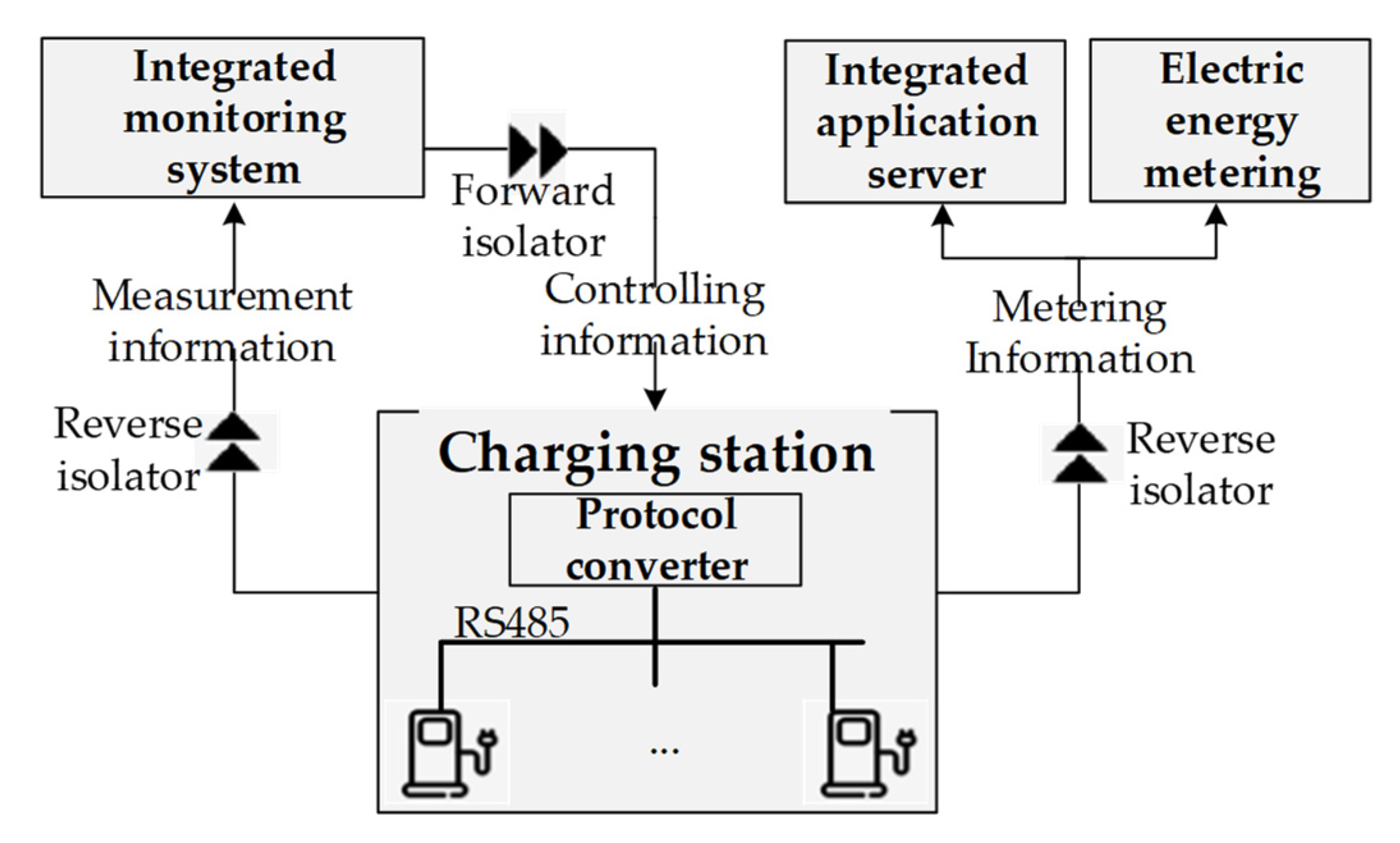
In SESt, the charging station needs to communicate with Zone I and Zone II. The communication information includes measurement information, control instructions, and metering information. To ensure the security of other systems in SESt, physical isolators are deployed between the charging station network and other zones, as illustrated in
Figure 7. Forward and reverse isolators are deployed between the charging station protocol converter and Zone I. The measurement information is uploaded to the integrated monitoring system through the reverse isolator, and the control instructions issued by the integrated monitoring system are sent to the corresponding primary equipment of the charging station through the forward isolator. The reverse isolator is deployed between the charging station protocol converter and Zone II. The metering information of the charging station is sent to the electric energy metering system and the integrated application server. When deploying, the protocol converter, forward isolator, and reverse isolator can be placed indoors. Meanwhile, since the isolators do not support decryption, no encryption measures are required between the protocol converter and the isolators. If you take encryption measures, you need to add a decryption device.
The internal servers of the data center station are deployed in Zone III and Zone IV. The network of Zone III is connected to the integrated application server in Zone II through the forward and reverse isolators. Thus, the nearby storage and analysis of production data are achieved, and the production data are sent to the relevant main station systems through the integrated power data network. The external servers of the data center station are independently zoned, and there are no physical or logical connections between the external servers and other zones in SESt. According to the specific situation of the data center station, two outlets are configured in the network of external servers. One outlet connects to the power communication network for making full use of the communication resources of the power grid enterprises. Thus, rapid communication between different data center stations is realized, and a large information service network forms. Another outlet connects to the internet through a firewall for providing social users with a fast local access channel, which can enhance users’ service experience.
According to the stipulations of “General plan for the security protection of the secondary power system” and “Regulations on the security protection of electric power monitoring system”, we deploy special horizontal one-way security isolation devices between the production control zone and the management information zone. These devices are tested and certified by the nationally designated department. The isolation strength is close to physical isolation. Meanwhile, we deploy domestic hardware firewalls, devices with access control functions, or equivalent functional facilities between Zone I and Zone II for logical isolation. At the vertical connection between the production control zone and the wide area network, we use the power-specific vertical encryption authentication device, encryption authentication gateway, and equivalent functional devices tested and certified by the nationally designated department. Thus, two-way identity authentication, data encryption, and access control will be achieved. The selection scheme for isolation devices between different zones in
Figure 6 is illustrated in
Table 2.
6. Security Reinforcement Solutions
Compared with traditional substations, SESt has wide control surfaces, complex systems, and strong interactions between sub-systems. It is more likely to suffer cyber attacks. To resist cyber attacks, it is necessary to further strengthen cyber security protection based on the secure zoning and isolation scheme.
As far as we know, IEC 61,850 communication standard and transmission control protocol/internet protocol (TCP/IP) are widely used in substations and photovoltaic stations. In addition, IEC61850 protocol, Modbus protocol, or TCP/IP are usually used between the battery management systems (BMSs) and the monitoring system of the energy storage station. On this basis, the communications in SESt can still use IEC 61,850 protocol and TCP/IP. Hence, the cyber security solutions designed in this section for the SESt also use IEC 61,850 protocol.
6.1. VLAN-Based Traffic Isolation Scheme for the Station-Level Network
To achieve information and function sharing, Zone I of the station level transmits multiple services on the same network. This results in that SESt’S station level have different service flows competing for network resources, and even the security of service flows may affect each other. If there is only one broadcast domain in Zone I of the station level, it may affect the overall transmission performance of the network in Zone I. When the station-level network is attacked, all communication services will be affected. To this end, this paper proposes to isolate different service flows logically by dividing VLANs, as shown in
Figure 8.
In
Figure 8, real-time services of the substation, real-time services of the energy storage station, real-time services of the photovoltaic station, real-time services of the charging station, and non-real-time services are divided into different VLANs. The broadcast information in each VLAN can only be received by its members, and will not be transmitted to other VLANs. Thus, unnecessary broadcast storms can be avoided. At the same time, there is no direct communication between different VLANs, thereby improving the security between different service flows. Administrators can fully manage mutual access and information sharing within Zone I by configuring access control policies. The scheme can simplify deployment, save resources and avoid mutual interference between different service flows.
6.2. Real-Time Guarantee Scheme for Communication Services Based on Service Priorities
IEC 61,850 specifies that the priorities of generic object oriented substation event (GOOSE) message and sampled measure value (SMV) message are high priority 4, the priorities of the other messages are low priority 1, and the IEEE802.1Q priority tag is used for holding the priority value [
24]. The SESt in this paper is based on the structure of “three layers, two networks”. Four stations (i.e., the substation, energy storage station, photovoltaic station, and charging station.) share the station-level network. The process-level network of the substation is independently networked. The main transmitted message types through the station-level network are manufacturing message specification (MMS) and simple network time protocol (SNTP) messages. If the two-level priority scheme is directly applied to SESt, there are the following problems.
(1) The station-level network is relatively independent of the process-level network. The high-priority messages and raw data messages are transmitted in the process-level network, while the other low-priority messages are all transmitted in the station-level network. Therefore, the default two-level priority scheme loses its significance, and the priority of all messages is the same without distinguishing between different types of services in the station-level network.
(2) At the station level, different communication services (e.g., control constructions, device condition, file transfer information, and alarm) have different delay requirements and traffic in SESt, and their importance to the SESt’s operation control is also different. Using the same priority cannot provide diverse services for communication services and may cause mutual influence between different services. When a substation fails or suffers cyber attacks, the network at the station level may incur congestion. This situation may affect the transmission of the remaining key real-time communication services, and even affect the entire SESt. Therefore, the two-level priority scheme in IEC 61,850 is not suitable for SESt’s station-level network.
To ensure the quality of service (QoS) of key services at SESt’s station level when the network occurs congestion, we propose a priority scheme for SESt. The priorities of the services at SESt’s station level are assigned considering the delay requirements, the importance to SESt’s operation control, and the traffic in this paper. Meanwhile, its queue scheduling method is presented.
6.2.1. New Priorities for Communication Services at the Station Level
The communication services at the station level do not have high real-time requirements, but different types of services have different real-time requirements. Therefore, the priority scheme based on communication services is more accurate and can better meet the real-time requirements of communication services at SESt’s station level.
One packet based on the IEEE802.1Q protocol inserts a 4-byte label after the MAC of the Ethernet frame header. The 3-bit priority field in the label can set 8 priorities, namely priority 0~7. However, for the unmarked frame (i.e., the frame does not contain the IEEE 802.1q tag), the switch will automatically add a label to the data frame after recognition, and the priority field in the label defaults to 1. Priority 0 is not recommended, because it may cause unpredictable delay. Therefore, the service priority scheme in this paper is selected from priority 1 to 7.
From the perspective of the safe and stable operation of SESt, the transmission sequence of service can be determined according to the importance to the operation control of SESt, real-time requirement, and traffic of service flow. The service priority scheme in this paper and the priority scheme in IEC61850 are shown in
Table 3. The detailed analysis can refer to our previous work [
25].
6.2.2. Switch Queue Scheduling Algorithm for New Service Priorities
At present, the strict priority queue (SPQ) scheduling algorithm is commonly used in power industry switches. This algorithm preferentially processes the packets in the high-priority queue. Only when the high-priority queue is empty, will the packets in the low-priority queue be processed [
26]. If the SPQ scheduling algorithm is used in SESt, all the other real-time services will be affected once a certain kind of real-time service traffic increases sharply. This is because all the real-time services have no different priority. Therefore, it is necessary to design a new switch queue scheduling algorithm to fit the new service priority scheme. For this purpose, this paper proposes a queue scheduling algorithm of priority deficit weighted round robin (PDWRR), which combines the advantages of dynamic weighted round robin (DWRR) [
27] and SPQ. The algorithm principle of PDWRR is illustrated in
Figure 9, and the pseudo-code of PDWRR is shown as Algorithm 1.
| Algorithm 1 PDWRR |
| Input: packets; |
| Output: packets; |
| 1: When a packet arrives, the packet classifier checks the IEEE802.1Q user priority label in the packet header and puts the packet into the corresponding real queue Qi; |
| 2: According to the queue priority, queue traffic and service delay requirements, the queues (i.e., Q2, Q3, Q4, Q5, Q6, Q7) participating in DWRR scheduling are assigned reasonable weights; |
| 3: The scheduling processor first checks the queue (i.e., Q2~Q7). If there is a packet, the corresponding number of packets are taken from the queue (i.e., Q2~Q7) according to DWRR scheduling rule to form a virtual queue (i.e., VQ) and forward the packet; |
| 4: When there are no packets in the queue (i.e., Q2~Q7) and there are packets in the queue (i.e., Q1), the packets in the queue (i.e., Q1) are forwarded; |
| 5: Repeat from step 1 until all queues are empty and no packet arrives. |
In Algorithm 1, the low-priority queue stores non-real-time service information (e.g., auxiliary control device data, primary equipment condition monitoring data, and recording data), the high-priority queue stores real-time service information (e.g., control instructions, protection action, breaker position, status information, measurement value, warning information, non-electrical measurement value, modification of the set value, time tick). The polling and weighting of DWRR can allocate bandwidth to each queue fairly so that all real-time services have the opportunity to be scheduled. When any kind of real-time traffic increases sharply, the QoS of other real-time services cannot be affected. Thus, the impact of flood attacks on SESt will be reduced. Meanwhile, the strict priority strategy of SPQ guarantees the real-time performance of real-time services to the greatest extent. PDWRR combines the advantages of DWRR and SPQ. It gives an absolute priority and predetermined bandwidth to high real-time services. Hence, the high real-time service can be transmitted without interfering with each other. The QoS requirements of multiple services at SESt’s station-level network can be met. The simulation experiment and results are in our previous work [
25].
In practice, when the new prioritization method and queue scheduling algorithm (i.e., PDWRR) are used, the queue scheduling algorithm program of switches needs to be upgraded. Meanwhile, VLANs and service priorities need to be configured. When initializing the network, 5 VLANs are divided at the switch of SESt’s station level, and the service flows are allocated to the corresponding VLAN according to
Section 6.1. Moreover, the priorities are assigned according to
Table 2, and the scheduling queue scheme and weight for each VLAN are specified according to Algorithm 1. It should be noted that the data of each substation are transmitted to the integrated monitoring system through switches. Hence, the port of the switch connected to the integrated monitoring system need to be configured into all the five VLANs. Considering the compatibility with existing switches, the new priorities are all greater than or equal to 4. Therefore, when switches used in practice do not support the new priorities and queue scheduling algorithm, the data forwarding can still use the method before improvement without distinguishing the types of services at the station level.
6.3. An Enhancing Cyber Security Scheme Based on Improved IEC 62351
IEC has presented IEC 62351 [
28,
29,
30,
31] for the data and communication security of the IEC 61850 substations. However, the security capabilities provided by IEC 62351 have the following deficiencies:
- (1)
The security measures defined by IEC 62351 do not cover all the security requirements of SESt.
- (2)
Due to the limited processing ability of embedded devices, some recommended security algorithms (e.g., the high complex RSA algorithm) in IEC 62351 are not suitable for SESt.
6.3.1. Security Measures for Communications within the Station Level
Section 6.2 has pointed out that the communication services use the MMS protocol at the station level. MMS is an application protocol based on TCP/IP. Integrity, non-repudiation, authenticity, availability, and confidentiality are its main security requirements. According to the improvement scheme proposed by IEC 62351-4 [
30] and reference [
32], this paper proposes the security measures for SESt’s station level as follows:
- (1)
To protect the authenticity of MMS, we enable the sender-ACSE-requirements field and responder-ACSE-requirements field of the authentication functional unit (FU) of the association control service element (ACSE). Meanwhile, we define the data structure MMS_Authentication-value where the signature value is stored.
- (2)
To protect the integrity of MMS, we adopt the SM3 algorithm to hash MMS messages.
- (3)
To ensure the authenticity of device identity, we add a unique identifier of the device to the reserved sequence field of MMS messages.
- (4)
Because SM2 has the advantages of higher security, faster operation, and less resource consumption, to ensure the integrity, non-repudiation, and confidentiality of messages, we adopt the SM2 algorithm instead of the RSA algorithm defined in IEC 62351 to sign and encrypt high-speed MMS messages.
- (5)
For the low-speed MMS messages, we adopt the improved TLS. For the medium-speed MMS messages, we adopt the method of signature-then-encryption on the sending side and decryption-then-authentication on the receiving side.
- (6)
To protect MMS messages against replay attacks, we adopt the timestamp verification to distinguish between real-time packets and obsolete packets.
These measures can ensure the authenticity, integrity, confidentiality, and non-repudiation of MMS at SESt’s station level, and meet the real-time communication requirements [
32].
6.3.2. Security Measures for Communications within the Process Level
Most of the secondary devices at the process level are embedded terminals. Their computing resources are limited. The manufacturers usually lack the ability to develop security protection technologies. Thus, it is difficult to add the security protection measures shown in
Figure 5. To ensure the real-time performance and security of communication services at the process level, we recommend that the process level devices and the bay level devices in SESt use traditional point-to-point optical fiber communication without configuring the switches at the process level. This scheme can greatly reduce the cyber security risk.
If the process level and the bay level of SESt use Ethernet for communication, we can refer to GOOSE/SMV security measures proposed in [
32]. By adopting the security measures in [
32], the authenticity of device identity and message integrity can be ensured. In addition, the authenticity, integrity, availability, and non-repudiation of communication services at the process level can also be guaranteed.
The real-time performance of the above cyber security measures based on improved IEC 62351 was analyzed and verified in our previous work [
32]. Interested readers can consult this.
7. Security Analysis
The proposed cyber security protection solutions, which not only can guarantee the confidentiality of data but also can resist various attacks, and reduce SESt’s cyber security risk.
- (1)
Resistance to eavesdropping
SM2 algorithm ensures the confidentiality of high-speed MMS messages. Improved TLS is adopted to ensure the confidentiality of low-speed MMS messages. Medium-speed MMS messages adopt the encryption algorithm to ensure their confidentiality. These measures can effectively prevent data from being stolen.
- (2)
Resistance to unauthorized access, interception, forgery, tampering
The security zoning and isolation scheme in this paper can protect SESt against unauthorized access and interception. SM3 algorithm can protect MMS messages against unauthorized modification. Thus, forgery and tampering can be avoided. Furthermore, we adopt peer entity authentication based on the SM2 algorithm to verify the integrity and authenticity of MMS messages. In this way, attackers cannot arbitrarily tamper with or forge communication messages.
- (3)
Resistance to flood attack
The real-time guarantee scheme for communication services based on service priorities has the ability to isolate malicious traffic and can ensure the real-time and reliable transmission of key services in SESt’s station level once the network is congested.
- (4)
Non-repudiation
The unique identifier of the sender ensures that the device cannot deny its participation in the communication, which effectively protects SESt against repudiation attacks.
- (5)
Resistance to replay attack
Timestamp checking is used for distinguishing current packages and outdated packages, which effectively resists replay attacks.
8. Conclusions
SESt has diverse communication services, complex data exchanges, and wide exposure. Thus, SESt is vulnerable to cyber attacks. To ensure the safe operation of SESt, this paper studies the cyber security issues for multi-station integrated SESt. Firstly, the composition of SESt is presented and the secondary system architecture is designed. The designed secondary system architecture takes relative independence and shareability of resources and functions into account. Then, the data exchanges of SESt are analyzed considering the requirements of information collection and transmission of SESt. Furthermore, cyber security threats and requirements of SESt are illustrated for determining SESt’s security requirements. On this basis, the cyber security protection principle and protection system are proposed. The protection system design takes the current technical level and realizability into account and covers cyber security solutions for each layer of SESt. Finally, the security zoning and isolation scheme and reinforcement solutions are proposed. The security zoning and isolation scheme not only follows the traditional security protection principle of the power secondary system, but also takes the specificities of the charging station being placed outside and the data center station having both internal and external services into account. The proposed reinforcement solutions can protect communication services of SESt’s station level against flood attacks, tampering attacks, and forgery attacks. Thus, the integrity of messages of SESt’s station level and the availability of real-time communication services under flood attacks are ensured.
This work belongs to the category of passive defense, and cannot deal with DoS attacks (e.g., malformed message attacks) other than flood attacks. The solution of secret key management is not involved in this paper, so we suggest using the existing power public key infrastructure (PKI) in practice. The active security defense measures and distributed secret-key management schemes for SESt would be the future study topics.


