
Three-Dimensional Non-Stationary MIMO Channel Modeling for UAV-Based Terahertz Wireless Communication Systems

 ,
, 
Abstract
1. Introduction
1.1. Motivation
1.2. Related Work
1.2.1. UAV-Based Channels
1.2.2. THz Channel
1.2.3. UAV-Based THz Channel
1.3. Contribution of Paper
2. 3D Non-Stationary UAV-MIMO Channel Model
2.1. Description of the THz UAV-MIMO Communication System
2.2. CIRs of the UAV-Based A2A Wireless Channel
2.2.1. LoS Propagation Path
2.2.2. NLoS Propagation Path
3. Statistical Properties of the Proposed UAV-Based Air-to-Air MIMO Channel Model
3.1. Space–Time Correlation Function
3.2. Doppler Power Spectrum Density
4. Numerical Results and Analysis
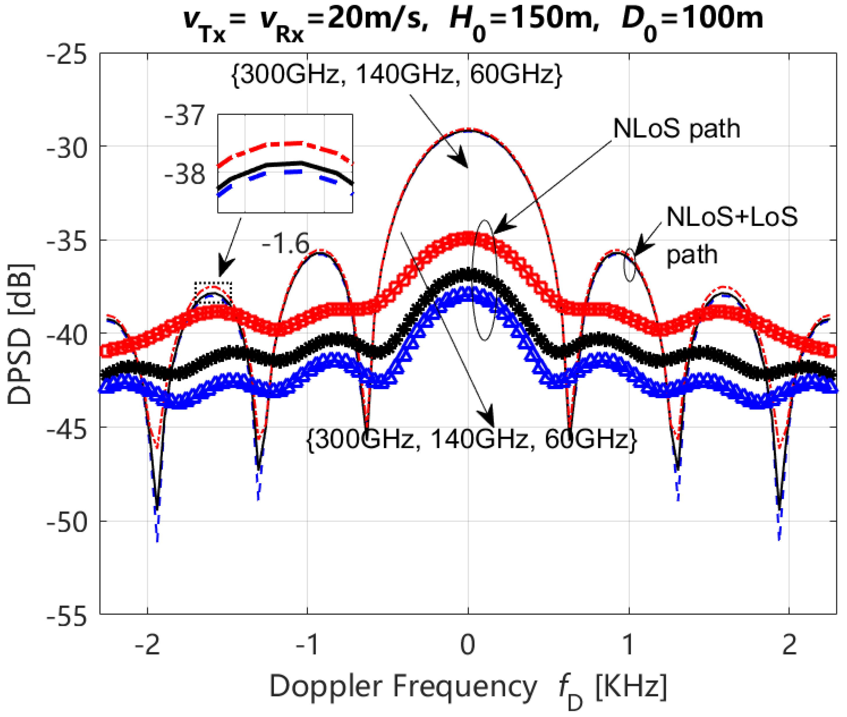
- (1)
- The DPSDs of LoS + NLoS and NLoS paths exhibited an increase with an increase in the carrier frequency. The result of the NLoS path is more obvious than that of the LoS + NLoS path.
- (2)
- The range of DPSDs variations for LoS + NLoS paths is greater than that observed for NLoS paths at different carrier frequencies.
5. Conclusions
Author Contributions
Funding
Data Availability Statement
Conflicts of Interest
Abbreviations
| Abbreviation | Description |
| SAGINs | Space–air–ground–sea integrated networks |
| MIMO | Multiple-input multiple-output |
| 6G | Sixth generation |
| UAV | Unmanned aerial vehicle |
| THz | Terahertz |
| 3D | Three-dimensional |
| T-ACF | Time autocorrelation function |
| S-CCF | Space cross-correlation function |
| DPSD | Doppler power spectrum density |
| mmWave | Millimeter wave |
| A2G | Air-to-ground |
| A2A | Air-to-air |
| AFD | Average fading duration |
| STC | Space–time correlation |
| STFC | Space–time–frequency correlation |
| GSCM | Geometry-based stochastic channel model |
| Tx | Transmitter |
| Rx | Receiver |
| LoS | Line-of-sight |
| NLoS | Non-line-of-sight |
| CIR | Channel impulse response |
| MPCs | Multipath components |
References
- Wang, C.X.; Huang, J.; Wang, H.; Gao, X.; You, X.; Hao, Y. 6G wireless channel measurements and models trends and challenges. IEEE Veh. Technol. Mag. 2020, 15, 22–32. [Google Scholar] [CrossRef]
- Bian, J.; Wang, C.X.; Liu, Y.; Tian, J.; Qiao, J.; Zheng, X. 3D Non-Stationary Wideband UAV-to-Ground MIMO Channel Models Based on Aeronautic Random Mobility Model. IEEE Trans. Veh. Technol. 2021, 70, 11154–11168. [Google Scholar] [CrossRef]
- Cheng, X.; Li, Y.; Wang, C.X.; Yin, X.; Matolak, D.W. A 3-D Geometry-Based Stochastic Model for Unmanned Aerial Vehicle MIMO Riciean Fading Channels. IEEE Internet Things J. 2020, 7, 8674–8687. [Google Scholar] [CrossRef]
- Lian, Z.; Su, Y.; Wang, Y.; Jiang, L.; Zhang, Z.; Xie, Z.; Li, S. A Non-Stationary 3-D Wideband Channel Model for Low Altitude UAV-MIMO Communication Systems. IEEE Internet Things J. 2022, 9, 5290–5303. [Google Scholar] [CrossRef]
- Ma, Z.; Ai, B.; He, R.; Wang, G.; Niu, Y.; Yang, M.; Wang, J.; Li, Y.; Zhong, Z. Impact of UAV Rotation on MIMO Channel Characterization for Air-to-Ground Communication Systems. IEEE Trans. Veh. Technol. 2020, 69, 12418–12431. [Google Scholar] [CrossRef]
- Ma, Z.; Ai, B.; He, R.; Wang, G.; Zhong, Z.; Yang, M.; Wang, J.; Li, Y. Impact of UAV Rotation on MIMO Channel Space-Time Correlation. In Proceedings of the 2020 IEEE 92nd Vehicular Technology Conference (VTC2020-Fall), Victoria, BC, Canada, 18 November–16 December 2021; pp. 1–5. [Google Scholar]
- Chang, H.; Wang, C.X.; He, Y.; Bai, Z.; Sun, J.; Zhang, W. Multi-User UAV Channel Modeling with Massive MIMO Configuration. In Proceedings of the 2021 IEEE 94th Vehicular Technology Conference (VTC2021-Fall), Norman, OK, USA, 27–30 September 2022; pp. 1–6. [Google Scholar]
- Tang, W.; Zhang, H.; He, Y.; Zhou, M. Performance Analysis of Multi-antenna UAV Networks with 3D Interference Coordination. IEEE Trans. Wirel. Commun. 2021, 21, 5145–5161. [Google Scholar] [CrossRef]
- Zhang, X.; Cheng, X. Second Order Statistics of Simulation Models for UAV-MIMORicean Fading Channels. In Proceedings of the 2019 IEEE International Conference on Communication (ICC2019), Shanghai, China, 20–24 May 2019; pp. 1–6. [Google Scholar]
- Bai, L.; Huang, Z.; Zhang, X.; Cheng, X. A Non-Stationary 3D Model for 6G Massive MIMO mmWave UAV Channels. IEEE Trans. Wirel. Commun. 2021, 21, 4325–4339. [Google Scholar] [CrossRef]
- Ma, Z.; Ai, B.; He, R.; Zhong, Z.; Yang, M. A Non-Stationary Geometry-Based MIMO Channels Model for Millimeter-Wave UAV Networks. IEEE J. Sel. Area Commun. 2021, 39, 2960–2974. [Google Scholar] [CrossRef]
- Ma, Z.; Ai, B.; He, R.; Zhong, Z.; Yang, M.; Wang, J.; Pei, L.; Li, Y.; Li, J. Three-dimensional Modeling Millimeter-Wave MIMO Channels for UAV-Based Communications. In Proceedings of the GLOBECOM 2020-2020 IEEE Global Communications Conference, Taipei, Taiwan, 7–11 December 2020; pp. 1–6. [Google Scholar]
- Zhang, Y.; Zhou, Y.; Ji, Z.; Lin, K.; He, Z. A Three-Dimensional Geometry-Based Stochastic Model for Air-to-Air UAV Channels. In Proceedings of the 2020 IEEE 92nd Vehicular Technology Conference (VTC2020-Fall), Victoria, BC, Canada, 18 November–16 December 2020; pp. 1–5. [Google Scholar]
- Huang, J.; Liu, Y.; Wang, C.X.; Sun, J.; Xiao, H. 5G Millimeter Wave Channel Sounders, Measurements, and Models: Recent Developments and Future Challenges. IEEE Commun. Mag. 2019, 57, 138–145. [Google Scholar] [CrossRef]
- Rappaport, T.S.; Xing, Y.; Kanhere, O.; Ju, S.; Madanayake, A.; Mandal, S.; Alkhateeb, A.; Trichopoulos, G.C. Wireless Communicationss and Applications Above 100 GHz: Opportunities and Challenges for 6G and Beyond. IEEE Access 2019, 7, 78729–78757. [Google Scholar] [CrossRef]
- Huq, K.M.S.; Busari, S.A.; Rodriguez, J.; Frascolla, V.; Bazzi, W.; Sicker, D.C. Terahertz-Enabled Wireless System for Beyond-5G Ultrafast Networks: A Brief Survey. IEEE Netw. 2019, 33, 89–95. [Google Scholar] [CrossRef]
- Ju, S.; Rappaport, T.S. 140 GHz Urban Microcell Propagation Measurements for Spatial Consistency Modeling. In Proceedings of the 2021 IEEE International Conference on Communication (ICC2021), Montreal, QC, Canada, 14–23 June 2021; pp. 1–6. [Google Scholar]
- Chen, Y.; Li, Y.; Han, C.; Yu, Z.; Wang, G. Channel Measurement and Ray-Tracing-Statistical Hybrid Modeling for Low-Terahertz Indoor Communications. IEEE Trans. Wirel. Commun. 2021, 20, 8163–8176. [Google Scholar] [CrossRef]
- Sun, S.; Rappaport, T.S.; Thomas, T.A.; Ghosh, A.; Nguyen, H.C.; Kovacs, I.Z.; Rodriguez, I.; Koymen, O.; Partyka, A. Investigation of Prediction Accuracy, Sensitivity, and Parameter Stability of Large-Scale Propagation Path Loss Models for 5G Wireless Communications. IEEE Trans. Veh. Technol. 2016, 65, 2843–2860. [Google Scholar] [CrossRef]
- Xing, Y.; Rappaport, T.S.; Ghosh, A. Millimeter Wave and Sub-THz Indoor Radio Propagation Channel Measurements, Models, and Comparisons in an Office Environment. IEEE Commun. Lett. 2021, 25, 3151–3155. [Google Scholar] [CrossRef]
- Xing, Y.; Rappaport, T.S. Propagation Measurements and Path Loss Models for sub-THz in Urban Microcells. In Proceedings of the 2021 IEEE International Conference on Communications (ICC2021), Montreal, QC, Canada, 14–23 June 2021; pp. 1–6. [Google Scholar]
- Guan, K.; Yi, H.; He, D.; Ai, B.; Zhong, Z. Towards 6G: Paradigm of Realistic Terahertz Channel Modeling. China Commun. 2021, 18, 1–18. [Google Scholar] [CrossRef]
- Akkas, M.A. Terahertz wireless data communication. Springer Wirel. Netw. 2017, 25, 145–155. [Google Scholar] [CrossRef]
- Khalid, N.; Akan, O.B. Wideband THz Communication Channel Measurements for 5G Indoor Wireless Networks. In Proceedings of the 2016 IEEE International Conference on Communications (ICC2016), Kuala Lumpur, Malaysia, 22–27 May 2016; pp. 1–6. [Google Scholar]
- Wang, J.; Wang, C.X.; Huang, J. A General 3D Space-TimeFrequency Non-Stationary THz Channel Model for 6G Ultra-Massive MIMO Wireless Communication Systems. IEEE J. Sel. areas Commun. 2021, 39, 1576–1589. [Google Scholar] [CrossRef]
- Wang, C.X.; Bian, J.; Sun, J.; Zhang, W.; Zhang, M. A survey of 5G channel measurements and models. IEEE Commun. Surv. Tutor. 2018, 20, 3142–3168. [Google Scholar] [CrossRef]
- Wang, J.; Wang, C.X.; Huang, J. A novel 3D non-stationary GBSM for 6G THz ultra-massive MIMO wireless systems. IEEE Trans. Veh. Technol. 2021, 70, 12312–12324. [Google Scholar] [CrossRef]
- Priebe, S.; Jastrow, C.; Jacob, M.; Kleine-Ostmann, T.; Schrader, T.; Kurner, T. Channel and Propagation Measurements at 300 GHz. IEEE Trans. Antennas Propag. 2011, 59, 1688–1698. [Google Scholar] [CrossRef]
- Han, C.; Chen, Y. Propagation Modeling for Wireless Communications in the Terahertz Band. IEEE Commun. Mag. 2018, 56, 96–101. [Google Scholar] [CrossRef]
- Han, C.; Bicen, A.O.; Akyildiz, I.F. Multi-ray channel modeling and wideband characterization for wireless communications in the terahertz band. IEEE Trans. Wirel. Commun. 2015, 14, 2402–2412. [Google Scholar] [CrossRef]
- He, D.; Guan, K.; Ai, B.; Fricke, A.; He, R.; Zhong, Z.; Kasamatsu, A.; Hosako, I.; Kurner, T. Channel modeling for Kiosk downloading communication system at 300 GHz. In Proceedings of the 2017 European Conference on Antennas and Propagation (EUCAP 2017), Paris, France, 19–24 March 2017; pp. 1331–1335. [Google Scholar]
- Gureev, A.; Cherniakov, M.; Marchetti, E.; Gureev, I. Channel description in the low-THz wireless communications. In Proceedings of the 2017 IEEE Conference of Russian Young Researchers in Electrical and Electronic Engineering (EIConRus 2017), St. Petersburg and Moscow, Russia, 1–3 February 2017; pp. 1240–1243. [Google Scholar]
- Han, C.; Akyildiz, I.F. Three-Dimensional End-to-End Modeling and Analysis for Graphene-Enabled Terahertz Band Communications. IEEE Trans. Veh. Technol. 2017, 66, 5626–5634. [Google Scholar] [CrossRef]
- He, D.; Guan, K.; Fricke, A.; Ai, B.; He, R.; Zhong, Z.; Kasamatsu, A.; Hosako, I.; Kurner, T. Stochastic Channel Modeling for Kiosk Applications in the Terahertz Band. IEEE Trans. Terahertz Sci. Technol. 2017, 7, 502–513. [Google Scholar] [CrossRef]
- Kim, S.; Zaji, A. Statistical Modeling and Simulation of Short-Range Device-to-Device Communication Channels at Sub-THz Frequencies. IEEE Trans. Wirel. Commun. 2016, 15, 6423–6433. [Google Scholar] [CrossRef]
- Ekti, A.R.; Boyaci, A.; Alparslan, A.; Ünal, İ.; Yarkan, S.; Görçin, A.; Arslan, H.; Uysal, M. Statistical modeling of propagation channels for Terahertz band. In Proceedings of the 2017 IEEE Conference on Standards for Communications and Networking (CSCN 2017), Helsinki, Finland, 18–20 September 2017; pp. 275–280. [Google Scholar]
- Nie, S.; Nie, I.F.A.; Akyildiz, I.F. Three-dimensional dynamic channel modeling and tracking for terahertz band indoor communications. In Proceedings of the 2017 IEEE Annual International Symposium on Personal, Indoor, and Mobile Radio Communications (PIMRC 2017), Montreal, QC, Canada, 8–13 October 2017; pp. 1–5. [Google Scholar]
- Zhang, Y.; Zhao, L.; He, Z. A 3-D Hybrid Dynamic Channel Model for Indoor THz Communications. China Commun. 2021, 18, 50–65. [Google Scholar] [CrossRef]
- Zhang, K.; Wang, H.; Zhang, C.; Yu, X.; Dong, Y. Three-dimensional non-stationary geometry-based modeling of sub-THz MIMO channels for UAV air-to-ground communications. In Proceedings of the 2023 IEEE International Conference on Communications (ICC2023), Rome, Italy, 28 May–1 June 2023; pp. 2069–2074. [Google Scholar]
- Zhang, K.; Wang, H.; Zhang, C.; Yu, X.; Dong, Y. Three dimensional geometry based stochastic model for sub-terahertz air-to-air UAV-MIMO channels. In Proceedings of the 2023 IEEE/CIC International Conference on Communications in China (ICCC2023), Dalian, China, 10–12 August 2023; pp. 1–6. [Google Scholar]
- Zhang, K.; Zhang, F.; Li, Y.; Wang, X.; Yang, Z.; Liu, Y.; Zhang, C.; Li, X. A Three-Dimensional Time-Varying Channel Model for THz UAV-Based Dual-Mobility Channels. Entropy 2024, 26, 924. [Google Scholar] [CrossRef] [PubMed]
- Zhang, K.; Zhang, D.; Yang, Z.; Zhang, F.; Li, Y.; Wang, X.; Wang, G.; Tian, Q. 3D Time-Varying UAV-Based Channel Model for THz Air-to-Air Wireless Communications. In Proceedings of the 2024 IEEE 24th International Conference on Communication Technology (ICCT2024), Chengdu, China, 18–20 October 2024; pp. 1–6. [Google Scholar]
- Zhang, K.; Zhang, C.; Wang, H.; Yang, Z.; Yu, X.; Li, Y. Non-Stationary Channel Modelling for Wireless Communications Underlaying UAV-Based Relay Assisted IIoT Networks in the Sub-Terahertz Band. IEEE Internet Things J. 2024, 11, 26888–26900. [Google Scholar] [CrossRef]
- International Telecommunication Union. Radiocommunication Sector (ITU-R), Recommendation P.676-11, Attenuation by Atmospheric Gases. 2026. Available online: https://www.itu.int/rec/R-REC-P.676-11-201609-I (accessed on 15 July 2025).
- Sheikh, F.; Gao, Y.; Kaiser, T. A Study of Diffuse Scattering in Massive MIMO Channels at Terahertz Frequencies. IEEE Trans. Antennas Propag. 2020, 68, 997–1008. [Google Scholar] [CrossRef]
- Jansen, C.; Priebe, S.; Moller, C.; Jacob, M.; Dierke, H.; Koch, M.; Kurner, T. Diffuse Scattering from Rough Surfaces in THz Communication Channels. IEEE Trans. Terahertz Technol. 2011, 1, 462–472. [Google Scholar] [CrossRef]


| Symbol | Definition |
|---|---|
| , | Moving azimuth and elevation angles of Tx |
| , | Moving azimuth and elevation angles of Rx |
| , | Moving velocities of Tx and Rx |
| , | Vertical heights of Tx and Rx |
| D | Distance at the x-axis between Tx and Rx |
| r | Distribution radius of reflectors and scatterers around the Rx |
| , | Azimuth angle of departure (AAoD) and elevation AoD (EAoD) for the LoS path from the p-th antenna element of Tx to the q-th antenna element of Rx |
| , | Azimuth angle of arrival (AAoA) and elevation AoA (EAoA) for the LoS path from the p-th antenna element of Tx to the q-th antenna element of Rx |
| , | AAoD and EAoD for the reflection path from the p-th antenna element of Tx to n-th reflector, then to the q-th antenna element of Rx |
| , | AAoA and EAoA for the reflection path from the p-th antenna element of Tx to n-th reflector, then to the q-th antenna element of Rx |
| , | AAoD and EAoD for the scattering path from the p-th antenna element of Tx to m-th scatterer, then to the q-th antenna element of Rx |
| , | AAoA and EAoA for the scattering path from the p-th antenna element of Tx to m-th scatterer, then to the q-th antenna element of Rx |
| , | Random phases of scattering and reflection propagations caused by and , and they can be assumed to independently, uniformly, and randomly distributed in the interval of |
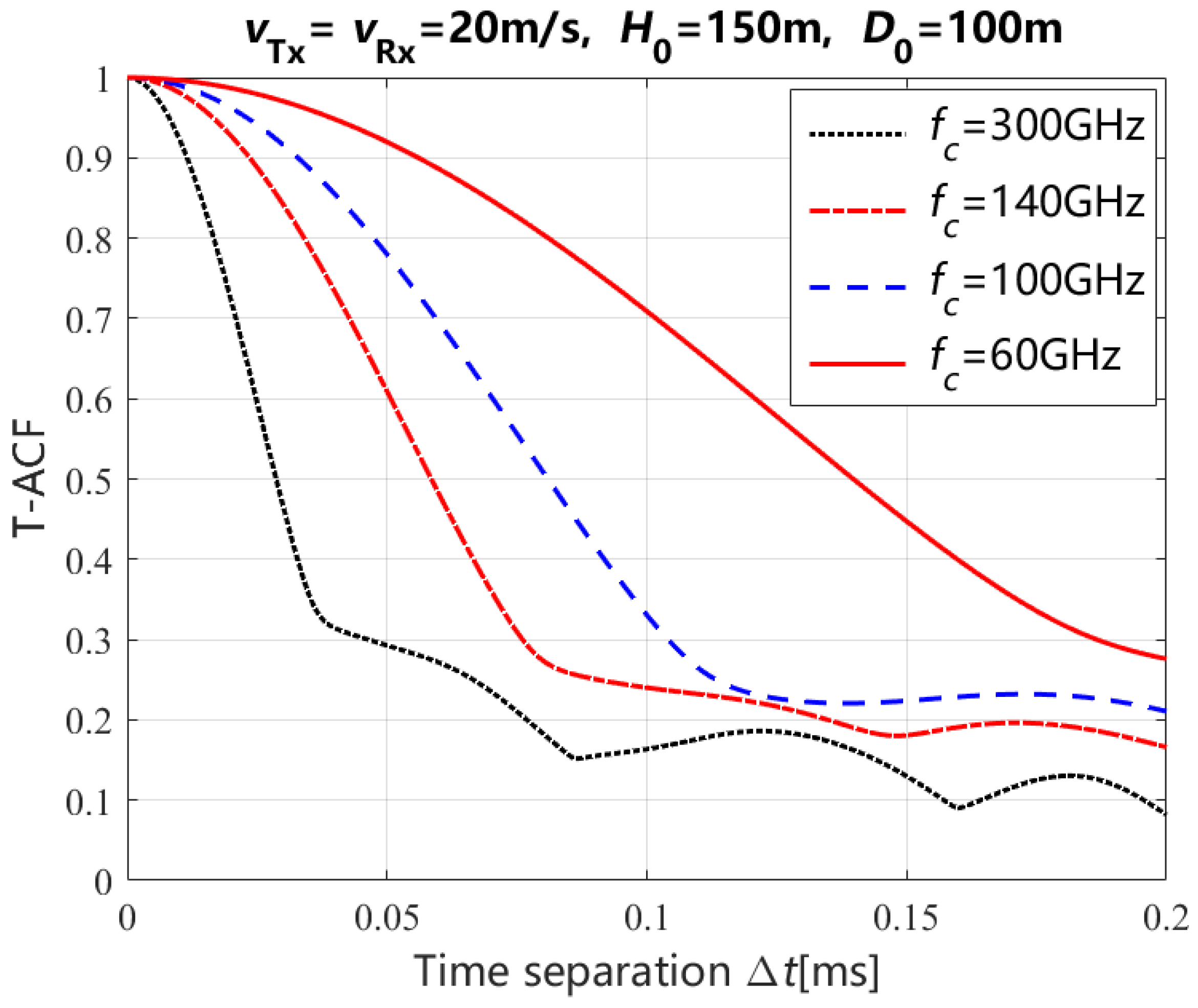
| Carrier Frequency | Stationary Time Separation |
|---|---|
| 300 GHz | 0.016 ms |
| 140 GHz | 0.034 ms |
| 100 GHz | 0.047 ms |
| 60 GHz | 0.081 ms |
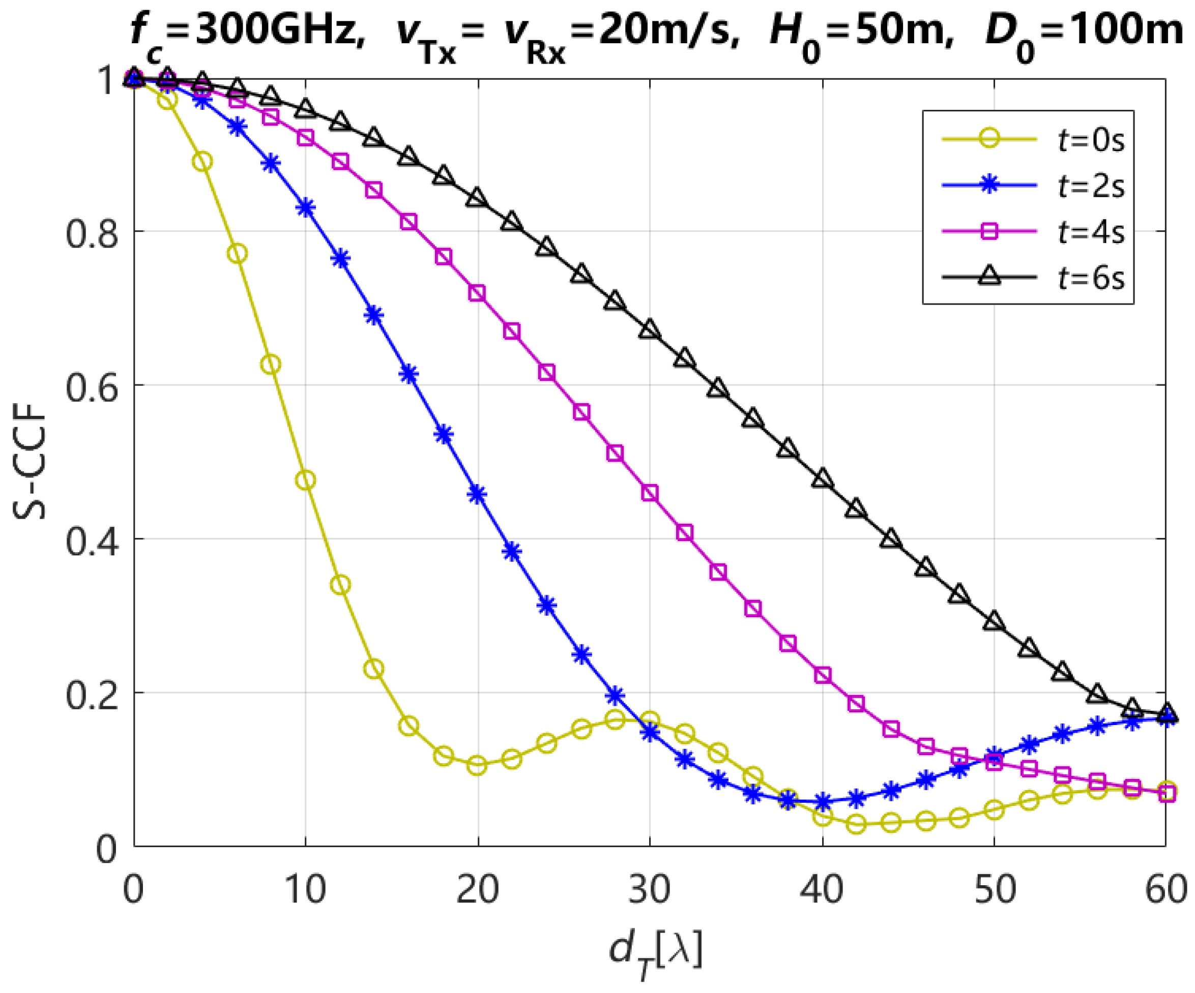
| Moving Time t | Element Spacing of Tx |
|---|---|
| 0 s | 8 |
| 2 s | 16 |
| 4 s | 24 |
| 6 s | 34 |
Disclaimer/Publisher’s Note: The statements, opinions and data contained in all publications are solely those of the individual author(s) and contributor(s) and not of MDPI and/or the editor(s). MDPI and/or the editor(s) disclaim responsibility for any injury to people or property resulting from any ideas, methods, instructions or products referred to in the content. |
© 2025 by the authors. Licensee MDPI, Basel, Switzerland. This article is an open access article distributed under the terms and conditions of the Creative Commons Attribution (CC BY) license (https://creativecommons.org/licenses/by/4.0/).
Share and Cite
Zhang, K.; Li, Y.; Wang, X.; Yang, Z.; Zhang, F.; Wang, K.; Zhao, Z.; Wang, Y. Three-Dimensional Non-Stationary MIMO Channel Modeling for UAV-Based Terahertz Wireless Communication Systems. Entropy 2025, 27, 788. https://doi.org/10.3390/e27080788
Zhang K, Li Y, Wang X, Yang Z, Zhang F, Wang K, Zhao Z, Wang Y. Three-Dimensional Non-Stationary MIMO Channel Modeling for UAV-Based Terahertz Wireless Communication Systems. Entropy. 2025; 27(8):788. https://doi.org/10.3390/e27080788
Chicago/Turabian StyleZhang, Kai, Yongjun Li, Xiang Wang, Zhaohui Yang, Fenglei Zhang, Ke Wang, Zhe Zhao, and Yun Wang. 2025. "Three-Dimensional Non-Stationary MIMO Channel Modeling for UAV-Based Terahertz Wireless Communication Systems" Entropy 27, no. 8: 788. https://doi.org/10.3390/e27080788
APA StyleZhang, K., Li, Y., Wang, X., Yang, Z., Zhang, F., Wang, K., Zhao, Z., & Wang, Y. (2025). Three-Dimensional Non-Stationary MIMO Channel Modeling for UAV-Based Terahertz Wireless Communication Systems. Entropy, 27(8), 788. https://doi.org/10.3390/e27080788