Owing to the existence of the in-plane quadrupole field, SU(3) SOC, rotation, and ferromagnetic spin interaction, no analytical solution exists for the coupled GP Equations (
3)–(5). In what follows, we use the imaginary-time propagation method (ITPM) based in the Peaceman–Rachford method (PRM) to numerically solve the two-dimensional GP Equations (
3)–(5), aiming to obtain the ground states by minimizing the total energy of the system [
32,
33]. The fundamental concept of the PRM is to transform a two-dimensional problem into one-dimensional problems, which can then be readily extended to three-dimensional case. The ITPM, utilizing the PR approach, exhibits excellent convergence, remarkable stability, and high precision. The convergence and accuracy of the algorithm are tested using the virial theorem, which establishes strict relationships between kinetic and potential energy contributions. Additionally, the energy functional and wave functions in the system converge rapidly, providing a second test. The algorithm also yields consistent results for different trial wave functions, serving as further validation. All these tests have been confirmed in our numerical computations. A notable characteristic of this system is the presence of a vast number of free parameters, including the rotation, SU(3) SOC, quadrupole field, ferromagnetic spin interaction, the density–density interaction, and spin–exchange interaction. Owing to the competition among multiple parameters, this system can display diverse ground-state structures and unusual topological excitations. In our simulation, we take into account the ferromagnetic spin interaction, i.e.,
. The typical parameters of the density–density and spin–exchange interactions are chosen as
and
, respectively.
3.1. Ground-State Structures and Spin Texture for the Nonrotating Case
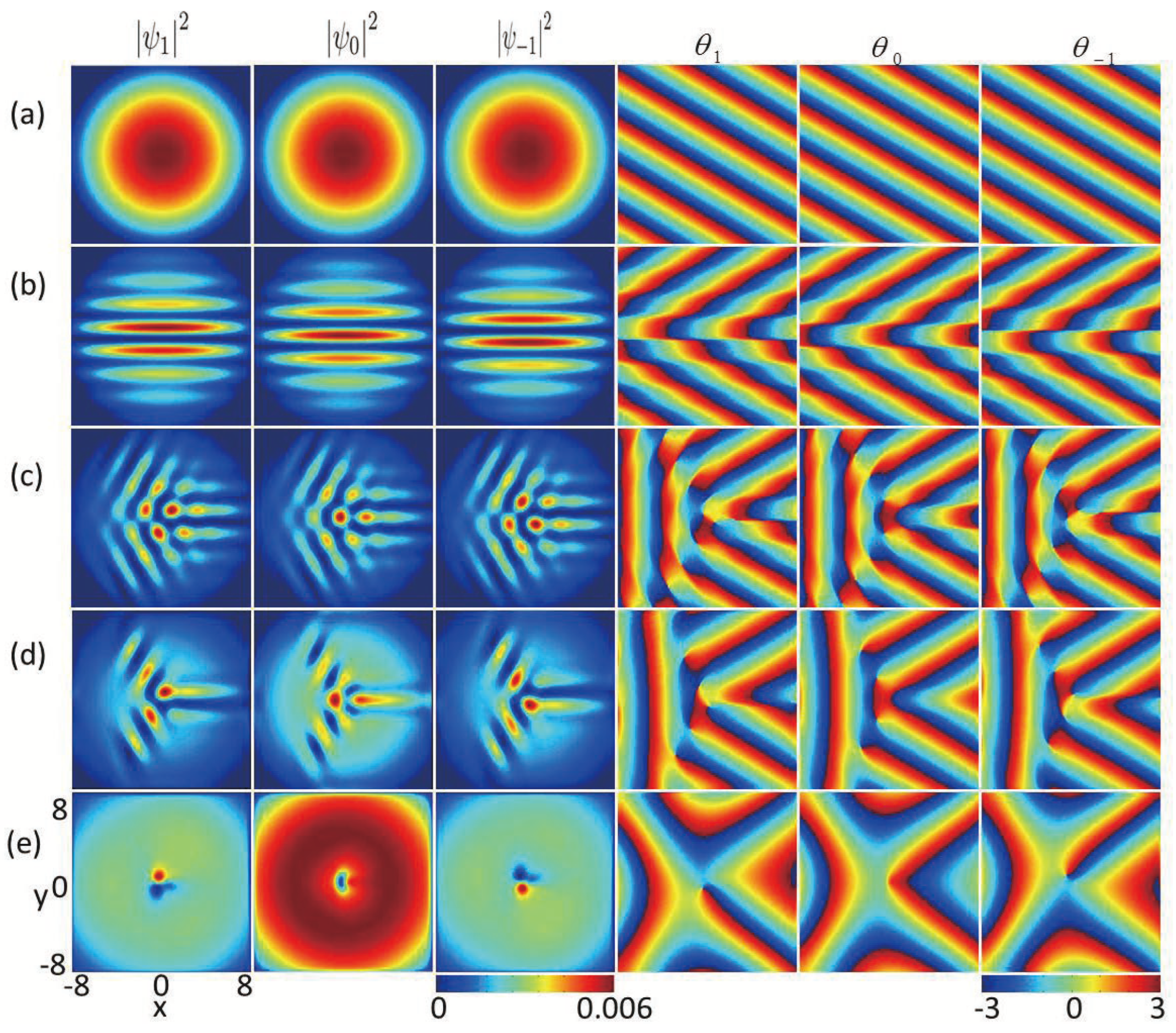
Firstly, we analyze how the in-plane quadrupole field affects the ground state of ferromagnetic spin-1 BECs with fixed SU(3) SOC
. In
Figure 1,
,
and
(three columns on the left side) denote the profiles of the density for the three components
,
, and
, and the relevant phase distributions are represented as
,
, and
(three columns on the right side), respectively. Without the in-plane quadrupole field strength (
), the system displays a completely mixed state and the maximum densities for the three components are centered at the harmonic trap, whereas the condensate’s phase fluctuates like a plane wave exp
, which is a Thomas–Fermi phase [
34] in
Figure 1a. For the very weak in-plane quadrupole field strength, i.e.,
, the densities of the system display a spatially separated stripe state along the
x direction, which is different from the stripe density patterns [
35] as a result of the existence of the in-plane quadrupole field. For the latter case, the stripe density results from the combined of dipole–dipole interaction and SU(2) SOC. As the in-plane quadrupole field strength increases, e.g.,
a vortex–antivortex cluster consisting of vortices and antivortices in each component forms and a few ghost vortices [
32,
36] are distributed in the outskirts of the atom cloud (see
Figure 1c). For the stronger in-plane quadrupole field (
) (see
Figure 1d), there are two vortices (clockwise rotation) and three antivortices (anticlockwise rotation) in component
, two vortices and two antivortices in component
, and two antivortices and three vortices in component
, respectively. As shown from
Figure 1c,d, the time-reversal symmetry is broken due to the joint influence of SU(3) SOC and the in-plane quadrupole field, which leads to the irregular distributions of phases for the three components. For a large quadrupole field strength, e.g.,
, we find that the vortices far from the condensate center disappear (
Figure 1e). The significant reduction in the number of vortices is a result of the reversal of magnetic moments derived from the in-plane magnetic fields. Here, the vortex configuration is characterized by the combination of winding numbers associated with every component. The configuration of windings can be written as
with the integers
being the winding numbers of
, respectively, and
w represents the phase shifts by
whenever the wave function circulates around the votex of the phase. We find that there are vortices in the core areas of components 1 and 3, and there are no vortice in the center of component 2, which gives rise to a polar-core vortex, in which the winding configuration is
with an antiferromagnetic core, as shown in
Figure 1c–e.
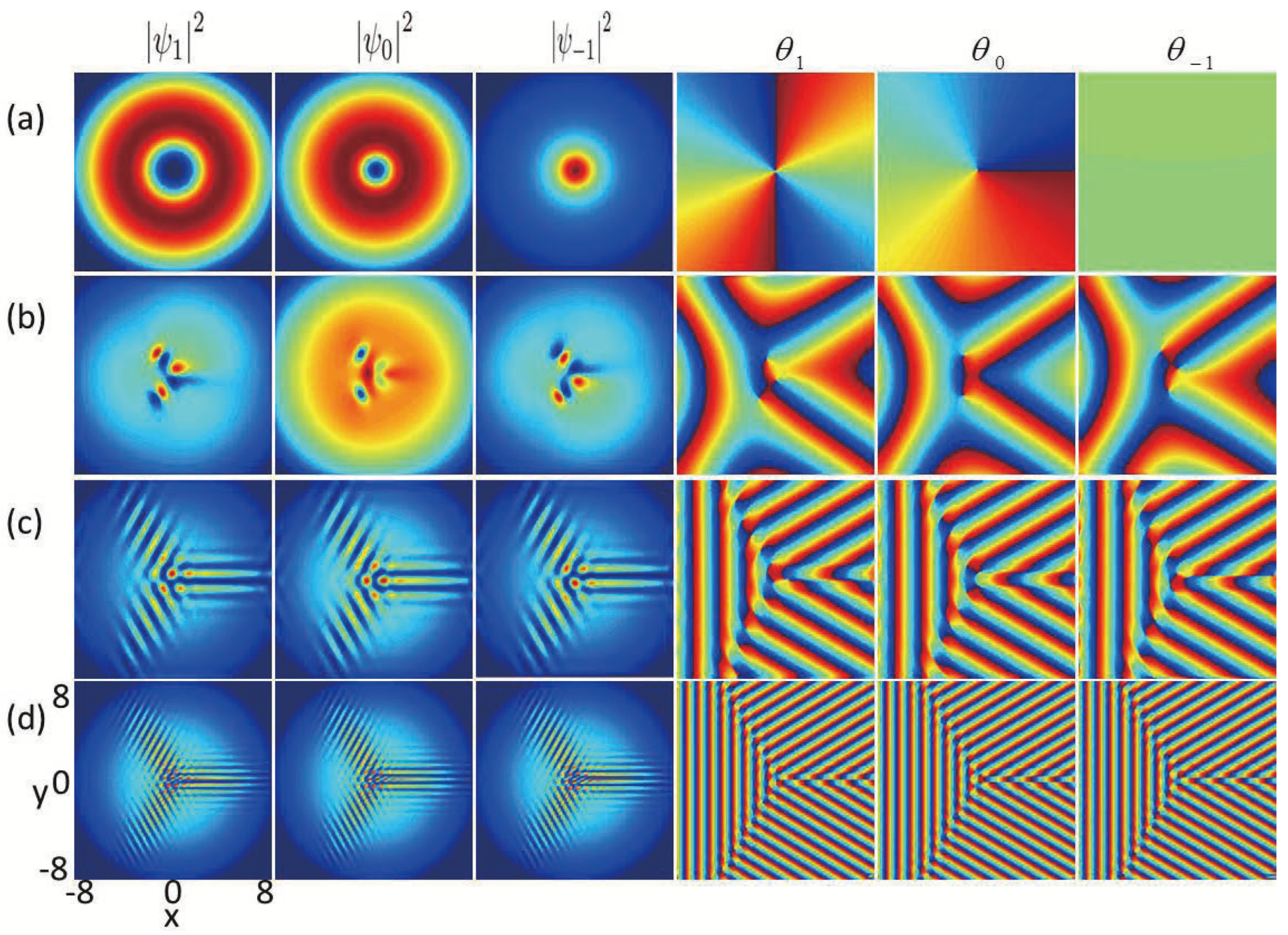
Secondly, we study the effects of SU(3) SOC on the ground-state structures of nonrotating spin-1 BECs with the existence of an in-plane quadrupole field. The strength of the quadrupole field is set to
, while all other related variables remain consistent with those in
Figure 1, except the SU(3) SOC strength. The primary findings are presented in
Figure 2. As shown in
Figure 2a, without SU(3) SOC
, the winding numbers located in the middle of the three components
are given by
. As a result, the vortex structure within this system belongs to a Mermin–Ho vortex [
37] (
Figure 2a), in which two quantized antivortices characterized by a winding number of
and a singly quantized antivortex characterized by winding number
are distributed in the middle of components
and
, respectively, while a bright soliton characterized by a zero winding number forms in the central area of component
. When the SOC strength
k is relatively small (e.g.,
), there is a triangular vortex–antivortex lattice composed of a vortex and two antivortices in component
, a vortex–antivortex pair in component
, and a triangular vortex–antivortex lattice consisting of two vortices and an antivortex in component
, respectively. With the SU(3) SOC strength
k increasing from
to
, more phase defects form in each component and they develop into a vortex chain and an antivortex chain, respectively, at an angle of approximate
as shown in
Figure 2c,d. The transformations of vortex structures in
Figure 2 are analogous to the topological phase transitions observed in nanomagnet systems [
38]. Essentially, this intriguing feature results from the competition between the SU(3) SOC and the quadrupole field in spin-1 BECs and is inaccessible in other systems, where the SU(3) SOC term in the Hamiltonian involves all the pairwise coupling between the three spin states [
20,
21]. From
Figure 1 and
Figure 2, by introducing the in-plane quadrupole filed and SU(3) SOC as two new degrees of freedom, we can achieve the desired ground-state configurations and control the phase transition among different ground states of spin-1 BECs.
Besides the line-like vortex excitation related to the spatial degrees of freedom of the BECs, the present system also supports topological excitations that are point-like in terms of the spin degrees of freedom, while skyrmions have already been observed in nuclear physics [
39], and quantum Hall systems [
40], creating these topological defects occurring ultracold gases could offer a novel platform for investigating their physical properties with higher precision. Moreover, owing to the exceptional purity and precise manipulability of the cold-atom system enable a thorough comparison between experimental observations and corresponding theories through skyrmion excitations in ultracold atomic gases. Combining SOC and rotation can result in a variety of topological excitations, such as circular skyrmion string [
16], circular-hyperbolic skyrmion [
18], giant skyrmion [
41], hyperbolic half-skyrmion [
42] and so on. Displayed in
Figure 3a,b are the topological charge density and spin texture corresponding to the parameters presented in
Figure 2a. The enlarged spin textures in the local region are given in
Figure 3c,d. The spin defect depicted in
Figure 3b is demonstrated to be an antiskyrmion characterized by a topological charge
. Recent studies have demonstrated that antiskyrmion in spin–orbit-coupled spin-1 BECs is Mermin–Ho vortex structure which can be written as
, where, in the bracket,
presents the
vortex characterized by a winding number
,
denotes the
vortex characterized by a winding number
,
is component
vortex characterized by a winding number
and the subscript 1 placed outside the bracket signifies the overlapping of the three vortices.
By comparison,
Figure 3e illustrates the topological charge density for nonrotating spin-1 BECs with SU(3) SOC, where
,
, and the ground state is exhibited in
Figure 2c. Notice that the component densities in
Figure 2c and the topological charge density in
Figure 3e are both approximately symmetric (or antisymmetric) with respect to the
axis. Considering the limited resolution of the texture, in
Figure 3f, we only show the spin texture in the
region, and the typical local amplifications of the full spin texture are given in
Figure 3g and
Figure 3h, respectively. Our numerical calculation shows that the red spots in
Figure 3f,g denote half-skyrmions (merons) with localized topological charge
[
18,
37]. Simultaneously, the blue spots in
Figure 3h indicate half-antiskyrmions possessing a localized topological charge of
. It is obvious that the spin defects in
Figure 3f form a half-skyrmion (meron) chain. Therefore the full spin texture corresponding to the ground-state structures in
Figure 2c consists of a half-skyrmion (meron) chain and a half-antiskyrmion (antimeron) chain, where the two chains form an angle of
. We call this special topological configuration a bending half-skyrmion–half-antiskyrmion (meron–antimeron) chain. Related studies have demonstrated that the half-skyrmion in quenched spin-1 BECs with SOC is associated with a three-vortex structure, which can be presented as
[
18,
43], i.e., each of the components
contains a vortex characterized by a winding number
and the subscript 3 outside the bracket indicates that the three vortices are located at three different positions. Thus, the structure composed of three vortices can be considered as a cell in which the ratio of vortices among the three components approaches 1:1:1.
3.2. Ground-State Structures and Spin Texture for the Rotating Case
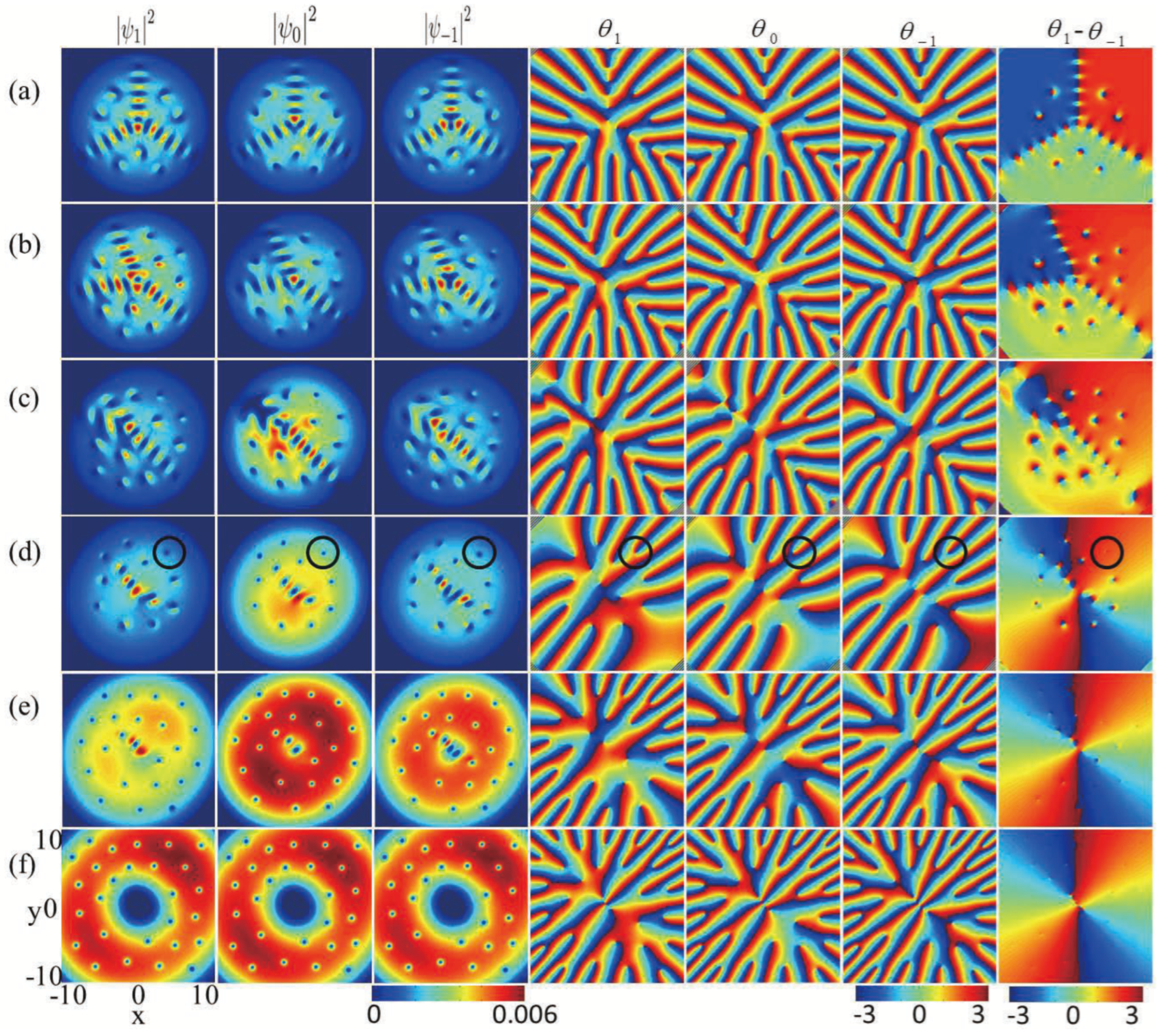
Now, we study the ground states of rotating SU(3) spin–orbit-coupled spin-1 BECs in the presence of an in-plane quadrupole field. Firstly, we consider the role of the in-plane quadrupole field with fixed rotation frequency
We begin with the case in which the quadrupole field is sufficiently weak (
. As shown in
Figure 4a, the density distribution for every component consists of three vortex chains extending from the center of the condensate, with angles of approximately
between any two chain. In addition, each of the three components is divided into three regions, which contain two vortices, two vortices, and three vortices, respectively. We call it a three-vortex-chain cluster structure. The phase difference presented in the final column of
Figure 4a indicates that the phases are not synchronized in the components
which differs from the cases of anisotropic SOC [
11,
18,
43]. With the relatively weak quadrupole field
, the angle between the two vortex chains, one aligned along the y-axis and the other in the third quadrant, decreases, while the vortex chain in the fourth quadrant remains unchanged. Meanwhile, the number of vortices in the regions divided by the vortex chains change, being one, four, and four, respectively. We can name this a tree-fork-like vortex chain cluster. With a further increase in the in-plane quadrupole field, e.g.,
the density distributions of three-vortex chains are destroyed due to the increased in-plane gradient magnetic field, and the vortices in individual components display diagonalized serpentine structures with some vortices distributed on both sides (see
Figure 4c), which is different from the vortex chain phenomenon observed in antisotropic spin-1/2 BECs with SOC [
11,
18] and spin-1 BECs [
17,
43]. Here, a diagonalized serpentine chain is the result of the interaction between the in-plane quadrupole field, SU(3) SOC, and rotation.
Physically, the interaction between the in-plane quadrupole field and SU(3) SOC induces a bending vortex–antivortex chain, with the vortex chain located in the second quadrant and the antivortex chain in the third quadrant (see the right three columns of
Figure 1c,d and those of
Figure 2c,d). Meanwhile, the joint influence of the SU(3) SOC and rotation sustains a three-vortex-chain structure, located, respectively, along the
y direction, in the third quadrant, and in the fourth quadrant, respectively (see
Figure 4a). Hence, the collaborative results of the in-plane quadrupole field, SU(3) SOC, and rotation generate the diagonal serpentine vortex chain. We have calculated the phase difference between any two components
and 1 in
Figure 4, for instance, the phase differences between
and
are displayed (the last column of
Figure 4). The calculation results show that the phases are desynchronized in
Figure 4a–c. Thus, all the vortices away from the vortex chain in the three components form the three-vortex configuration, differing from those in [
43]. Here the interesting three-vortex configurations are caused by the interplay and competition among the in-plane quadrupole field, the isotropic SU(3) SOC, and the rotation. As the in-plane quadrupole field further increases (see
Figure 4d–f), the vortices along the diagonal serpentine vortex chain decrease but those away from the diagonal serpentine vortex chain increase. By computing the phase differences between any two components
and 1 (see the final column of
Figure 4d–f), one can conclude that the phases gradually synchronize as the in-plane quadrupole field increases. Taking
Figure 4d as an example, the outmost vortices of the three components in the second quadrant overlap (see the black circle of
Figure 4d). For the case of
, by calculation, all vortices away from the density hole of the central region of the condensate overlap. The above can be explained as when the three vortices of the three components coincide, it will contribute more angular momentum and energy to the system. Therefore, the three vortices that overlap are more likely to appear in the low-density region of BECs (i.e., the boundary of BECs).
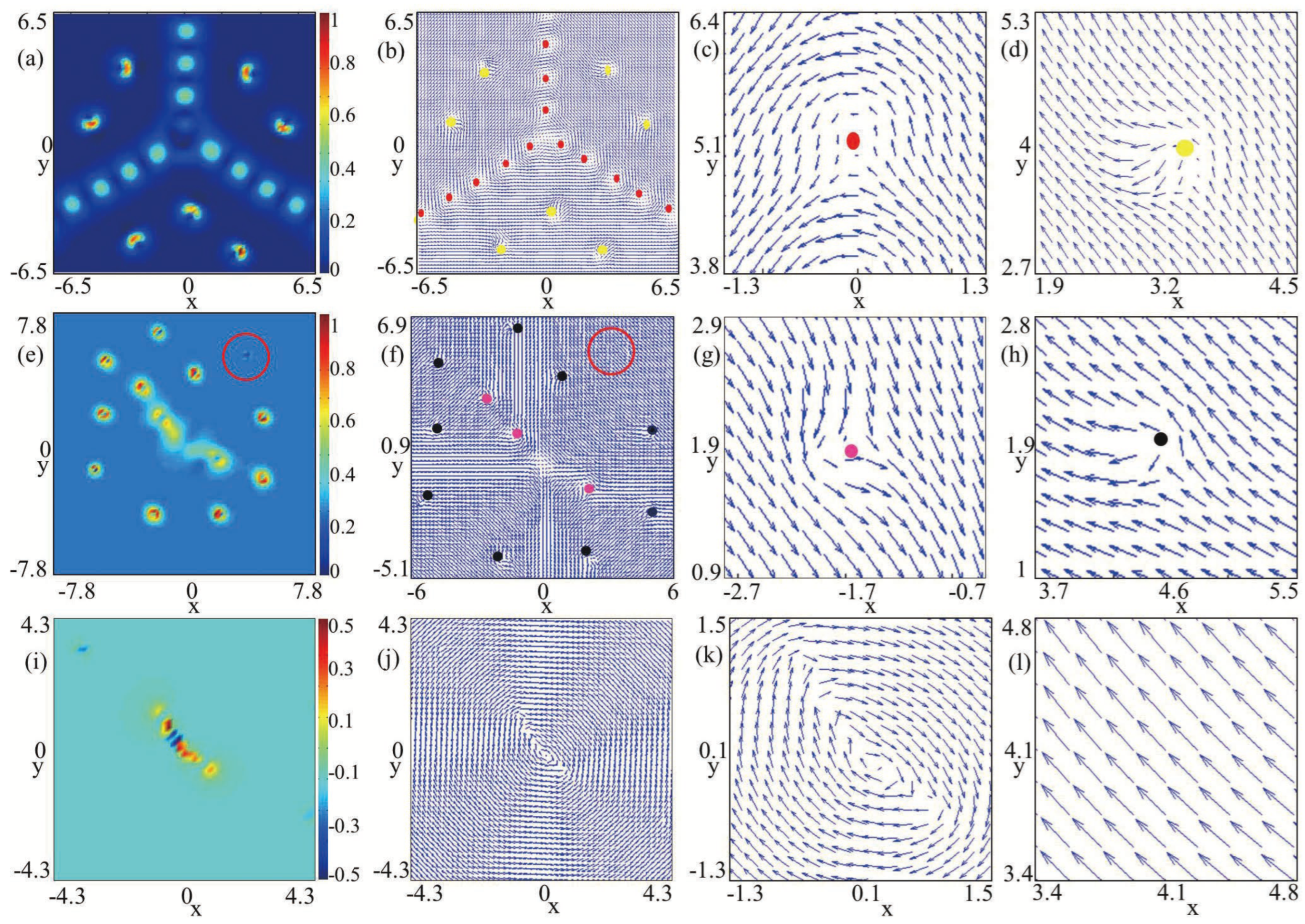
Figure 5a,b illustrates the topological charge density and spin texture characteristics of rotating spin-1 BECs with SU(3) SOC, respectively. The corresponding ground state is displayed in
Figure 4a. Notice that the topological charge density in
Figure 5a and the component densities in
Figure 4a are approximately symmetric about the
axis.
Figure 5c,d shows the prominent local magnifications of the spin texture in
Figure 5b. By comparison,
Figure 5e depicts the topological charge density for the SU(3) spin–orbit-coupled spin-1 BEC under rotation, where
,
, and
, and the ground state is exhibited in
Figure 4d. The distinctive local amplifications of the entire spin texture of
Figure 5f are given in
Figure 5g and
Figure 5h, respectively. Our numerical computation indicates that all the spots in
Figure 5b–d,f–h denote half-skyrmions (merons) with local topological charge
[
18,
37]. Note that different colored dots in
Figure 5 represent different shapes of spin textures corresponding to half-skyrmions, which result from the three-vortex structure. In addition, we find that the outermost vortices in the second quadrant of the three components did not form a clearly visible spin texture with topological density
(see the red circle of
Figure 5e–f). It can be explained that the outermost vortices in the second quadrant of the three components overlap with the
vortex configuration, which aligns with the phase difference of
Figure 4b.
The topological charge density and the spin texture are illustrated in
Figure 5i,j, and corresponding density and phase distributions are shown in
Figure 4f. Our numerical calculation shows that there is only an irregular elliptical shape half-skyrmion carrying topological charge
in the center of the condensate. Essentially, the above phenomenon is explained by the vortices away from the center of the condensate being overlapped in the three components. Therefore. these vortices can be written as
, where the subscript 1 placed outside the bracket signifies that the three vortices coincide.
Then, we study the effect of SU(3) SOC in Spin-1 BECs under rotation with given quadrupole field strength
. The parameters are identical to those mentioned in
Figure 4, with the exception of the strength of the SU(3) SOC. The density and phase distributions of the system’s ground states under different strengths of SU(3) SOC are displayed, where the fourth column represents the phase difference of components
. As depicted in
Figure 6a, without SU(3) SOC (i.e.,
), the distributions of component density and the arrangement of vortex structures exhibit regular distributions. The winding numbers in the central regions of BECs are
with a dark soliton at the core area of the component
. Thus, the vortex configuration in this system is an Anderson–Toulouse coreless vortice [
43,
44]. Additionally, each component contains six vortices surrounding the trap center, which evolve into a vortex necklace configuration in the azimuthal direction. The density distributions of the three components exhibit remarkable rotational symmetry. By calculating the phase difference between any two components (e.g., the phase difference of components
given in the last column of
Figure 6a), we find that six groups of the three-vortex structure cell are formed around the center of the condensates. With the increase of SU(3) SOC strength (see
Figure 6b,c), the central Anderson–Toulouse coreless vortice disappears, but the number of vortices clearly increases. As shown in
Figure 6c, a diagonalized serpentine chain forms; meanwhile, the other vortices are distributed as much as possible, beside the diagonalized serpentine chain (
Figure 6c). When the SU(3) SOC further increases, the diagonalized serpentine vortex chain is transformed into a tree-fork-shaped vortex chain cluster, in which the vortices increase significantly. The distributions of density and phase in
Figure 6d are similar to
Figure 4b. For the case of strong SU(3) SOC strength
, three vortex chains that extend from the center of the BECs form an angle of
between any two components and divide the condensate into three parts. In the meantime, we observe that as the SU(3) spin–orbit coupling increases, the component densities of the BECs expand more significantly. This point can be understood. Essentially, when SU(3) SOC (with a given in-plane quadrupole field and the remaining parameters) increases, more angular momentum and energy contribute to the system and lead to the generation of more phase singularities and the expansion of the atom cloud. At the same time, the vortices away from the vortex chains are nearly synchronized (the last column of
Figure 6e), therefore, the angular momentum and energy are carried by the vortices on the vortex chains (see
Figure 6e).
Essentially, the in-plane quadrupole field exhibits a distinctive saddle point structure that tends to orient the spin inward toward the plane, which effectively suppresses the formation of ordinary vortices. In contrast, the rotation causes every component to generate vortices characterized by a single winding number. Conversely, to reduce the energy associated with the spin–exchange interaction, the ferromagnetic interaction encourages the spins to align in the identical direction. Because ordinary vortices are associated with a sudden change in the spin near their cores, the ferromagnetic spin–exchange interaction effectively inhibits the formation of these vortices [
17]. In the absence of SU(3) SOC, the combined effect of an in-plane quadrupole field, rotation, and ferromagnetic spin interaction may result in the development of a regular density profile and vortex structure, as shown in
Figure 6a. When the SU(3) SOC enhances vortex formation, the increasing vortices resulting from stronger SU(3) SOC are more likely to adopt a symmetrical equilibrium configuration.
Now, to further elucidate the ground-state properties of
Figure 6, we investigate the spin textures within the system. Displayed in
Figure 7a is the topological charge density, and
Figure 7b shows the corresponding spin texture. The ground states are given in
Figure 6a.
Figure 7c,d shows the local enlargements of the spin texture in
Figure 7b. The results of our computations show that the topological excitation within the red circle pane corresponds to a circular skyrmion, characterized by a topological charge of
, and those in every green square pane belong to a half-skyrmion, characterized by a topological charge of
. Physically, the skyrmion highlighted within the red circular panel of the spin texture depicted in
Figure 7b is associated with the Anderson–Toulouse coreless vortex located In the middle areas of the condensates, where the winding number in the middle areas of the three components is combined as
. In
Figure 7b, the central circular skyrmion is encircled by six half-skyrmions in green square pane, which form a half-skyrmion necklace. So the topological structure of the system consists of an unusual skyrmion–half-skyrmion necklace, which is made up of a central skyrmion and an annular half-skyrmion (meron) necklace. As shown in
Figure 7e,f, the topological charge density and corresponding spin texture are presented, respectively, which aligns with
Figure 6b. Furthermore,
Figure 7g,h shows the local amplifications of
Figure 7f. In
Figure 7f,g, the red spots represent hyperbolic skyrmions [
39] with local topologial charge
, which is related to the Anderson–Toulouse coreless vortex located in the middle area of the condensates. In
Figure 7f–h, the local topological charge of every green dot is
, which indicates that the system’s topological structure is a nearly symmetric half-skyrmion (meron) lattice in relation to the diagonal line composed of a half-skyrmion, hyperbolic skyrmion, and a half-skyrmion. In comparison,
Figure 7i,
Figure 7j, and
Figure 7k,l display the topological density, spin texture, and local amplifications of the spin texture, where the ground state is displayed in
Figure 6d. Considering the limited resolution of the texture, we only show the spin texture in the core region in
Figure 7j, and the calculation results demonstrate that the topological defects in the rose red spots and yellow spots in
Figure 7j–l are half-skyrmions with topological charge
. Tree-fork-like half-skyrmions chains and half-skyrmions distributed between tree-fork vortex chains jointly form the topological configuration of this system. The spin textures correspond to the half-skyrmion in
Figure 3,
Figure 5 and
Figure 7 and are related to the three-vortex structures with a winding configuration
.

