
Impact of Spray Cone Angle on the Performances of Methane/Diesel RCCI Engine Combustion under Low Load Operating Conditions

 ,
,
Abstract
:1. Introduction
2. Numerical Method
2.1. Experimental Configuration
2.2. Diesel Surrogate for the Reaction Mechanism
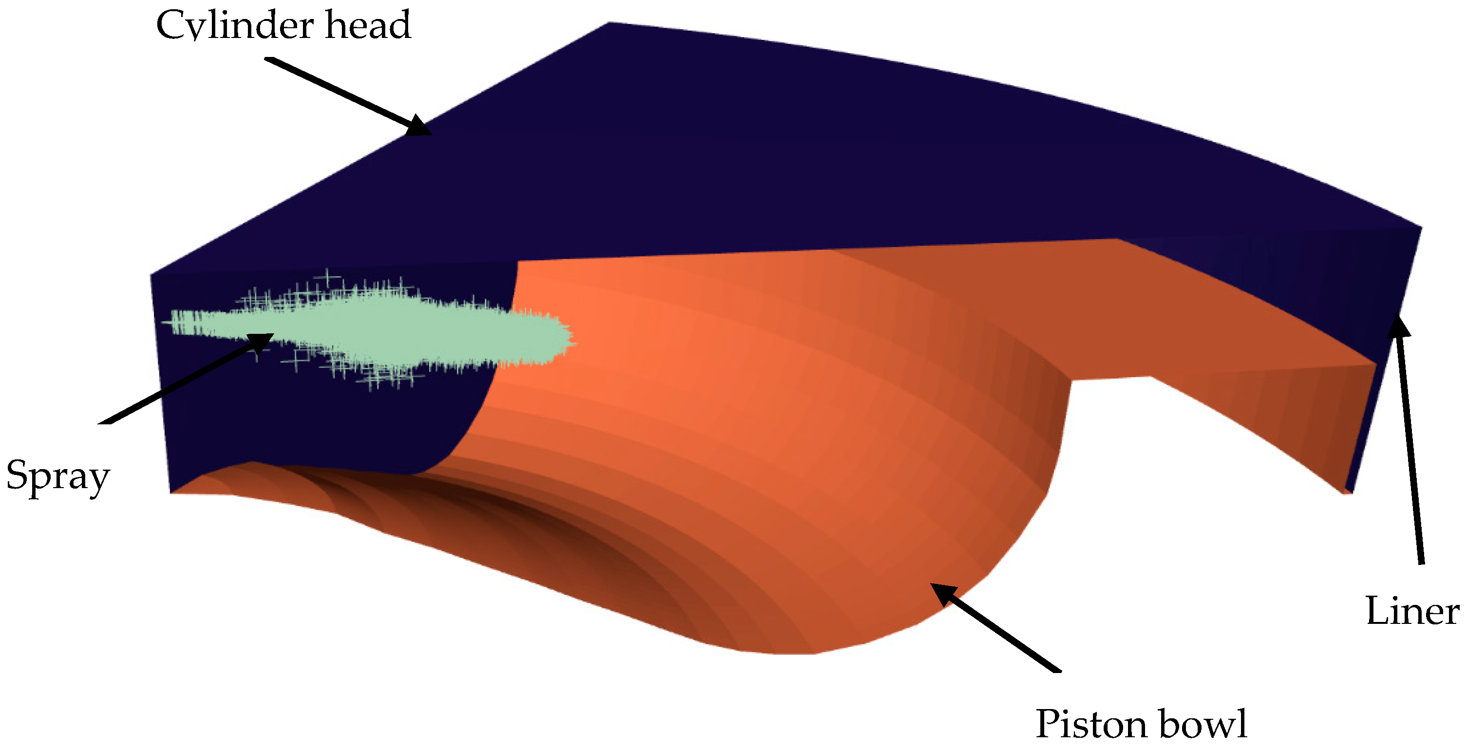
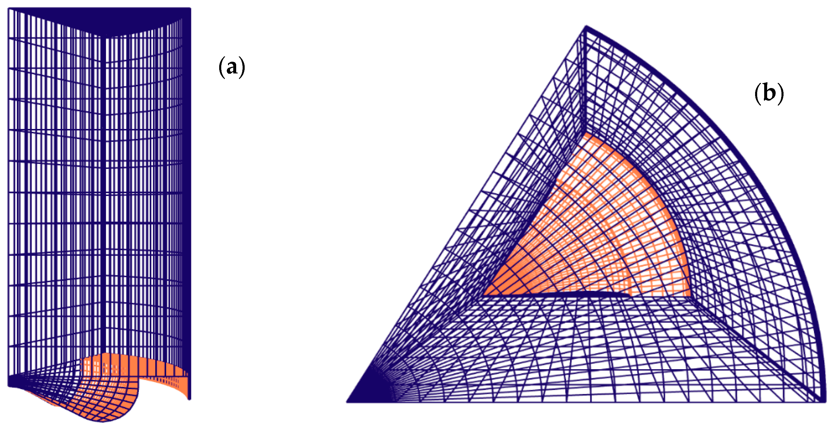
2.3. Mesh and Boundary Conditions
2.4. Governing Equations
2.5. Diesel Spray Model
2.6. Exergy Balance Analysis
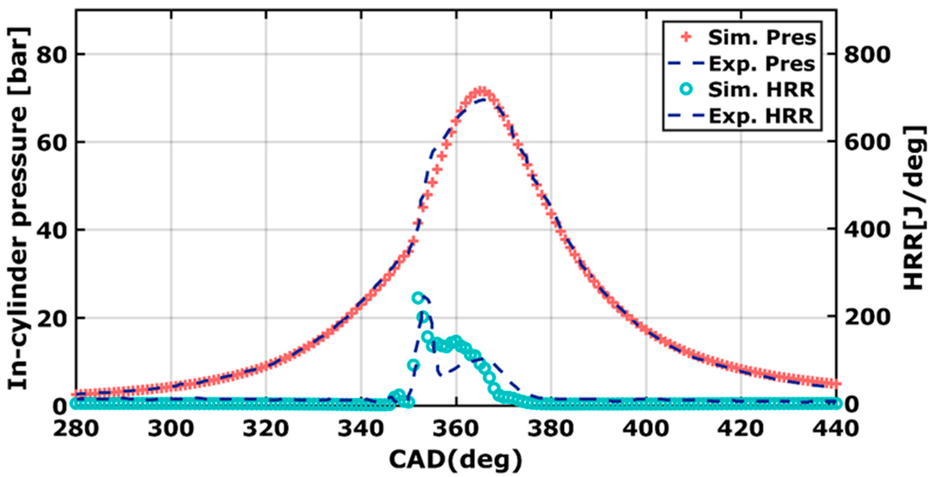
2.7. Model Validation
3. Results and Discussion
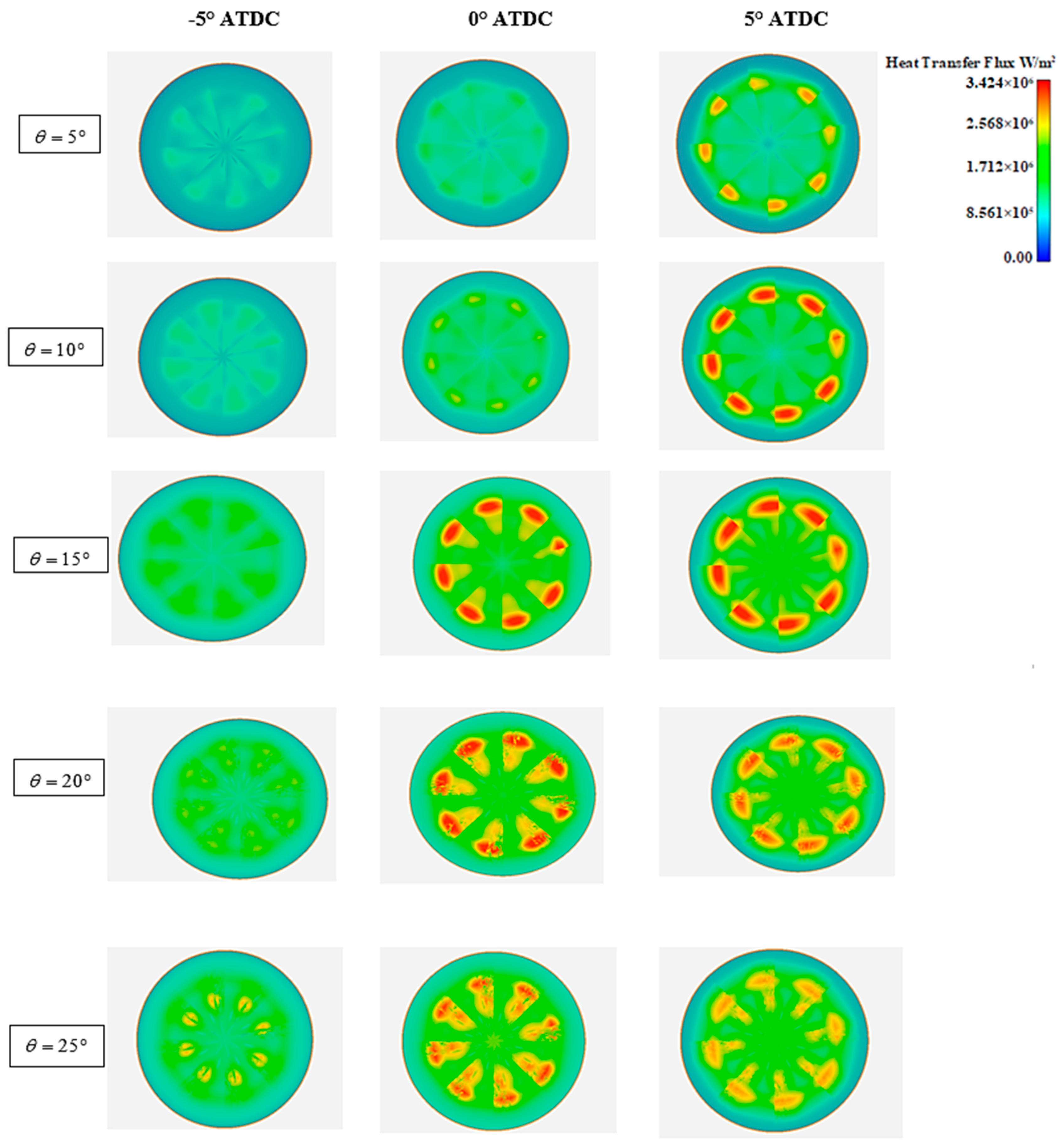
3.1. Distribution of Heat Transfer Flux
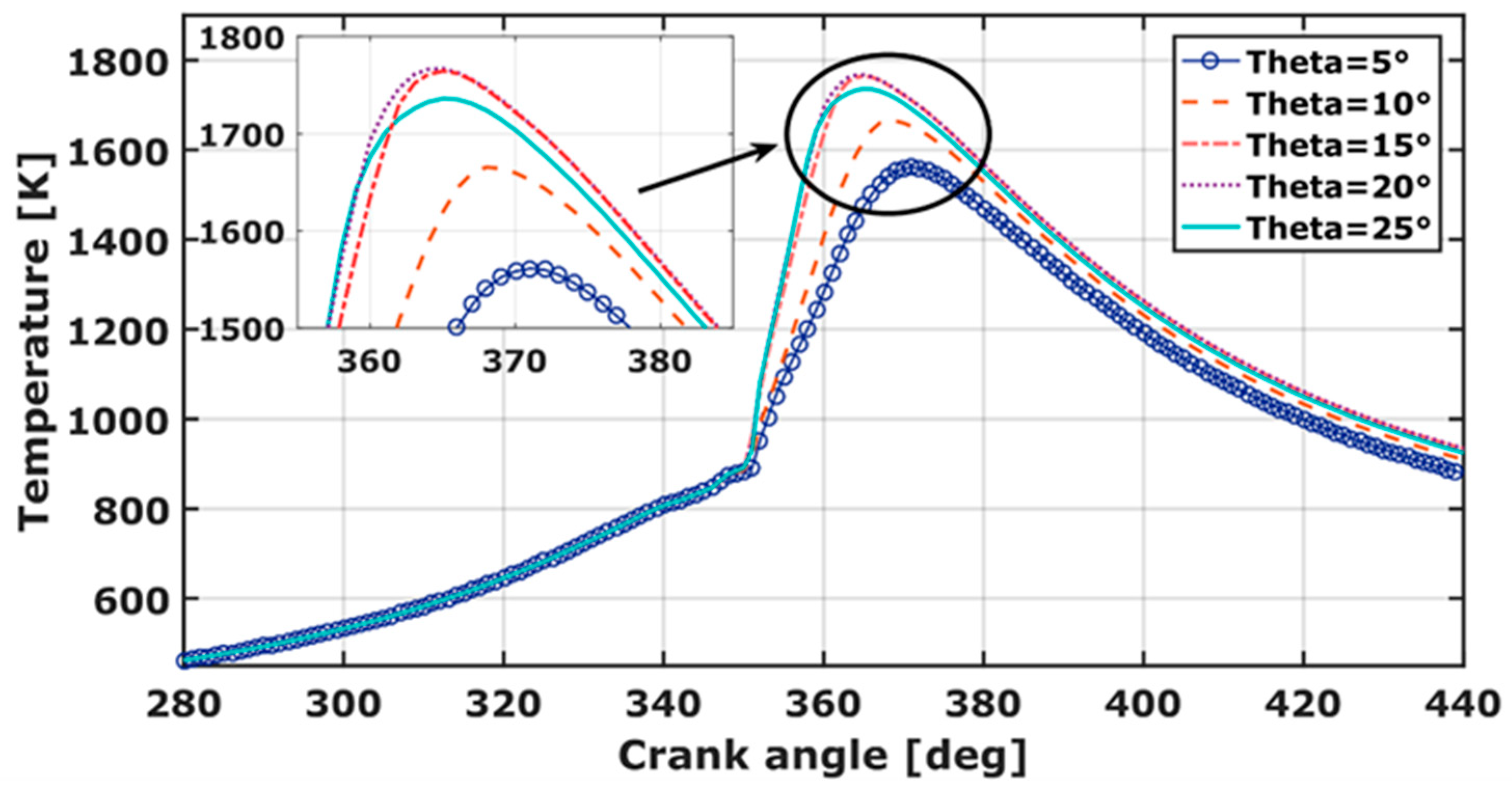
3.2. Temperature
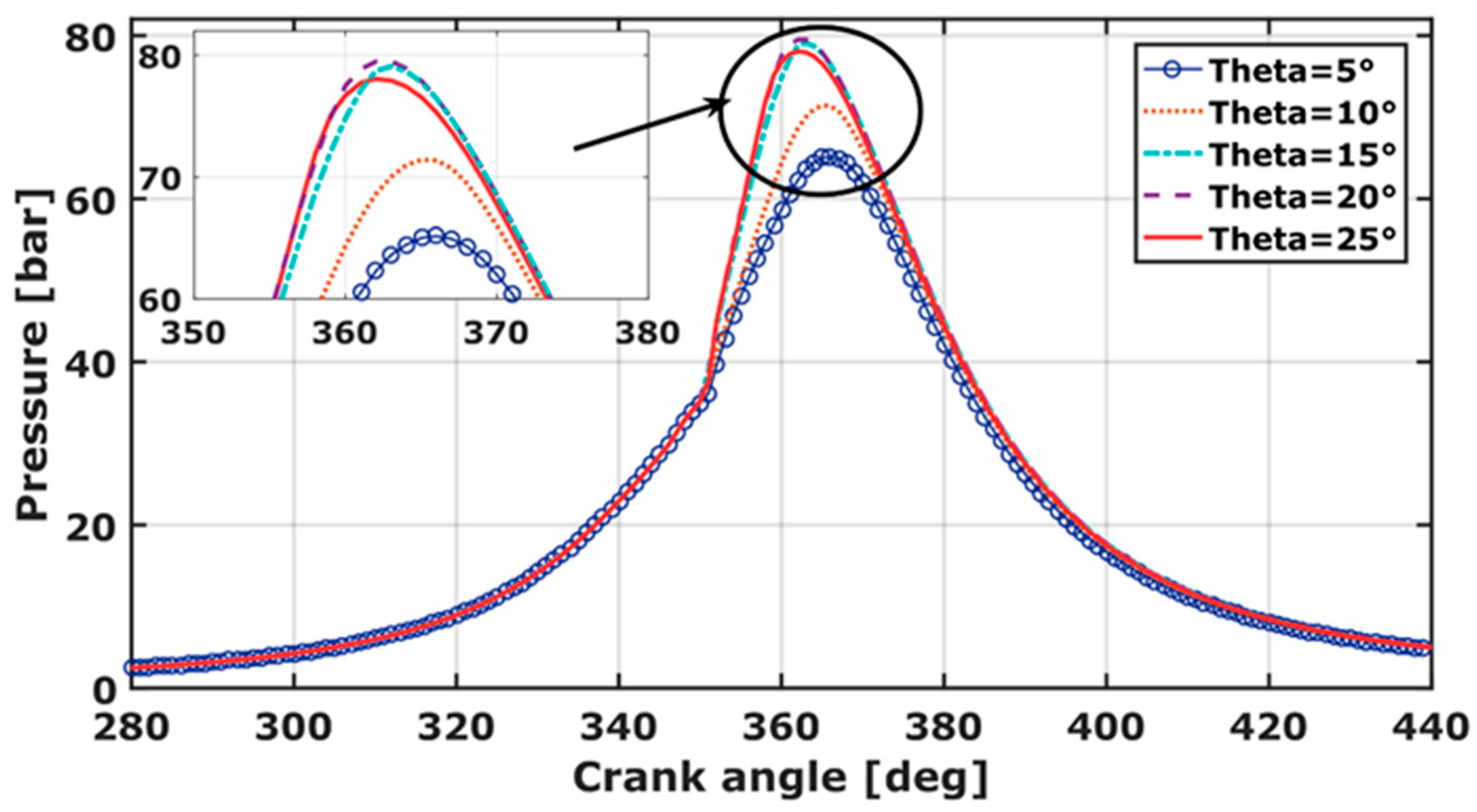
3.3. Pressure
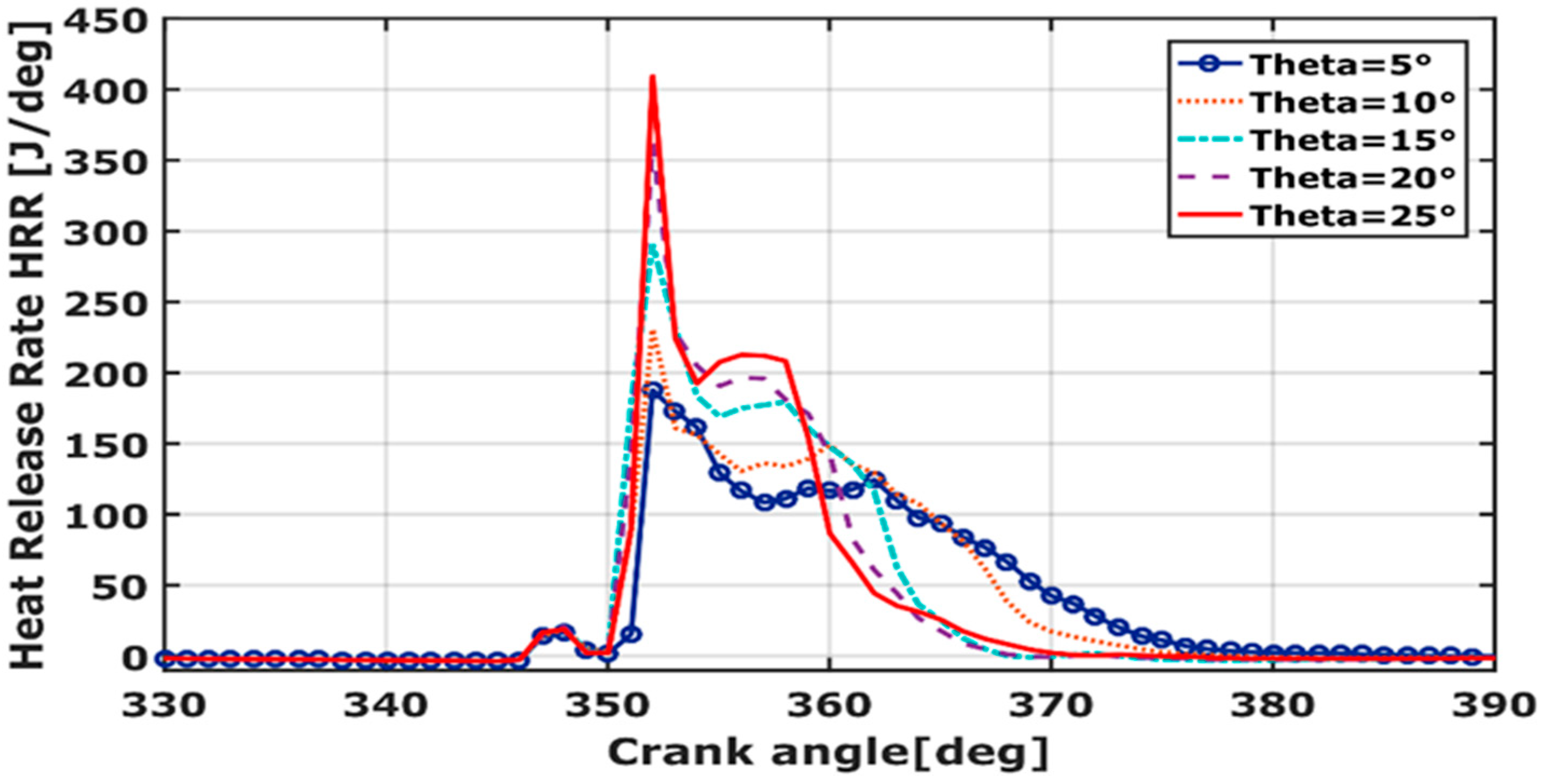
3.4. Heat Release Rate (HRR)
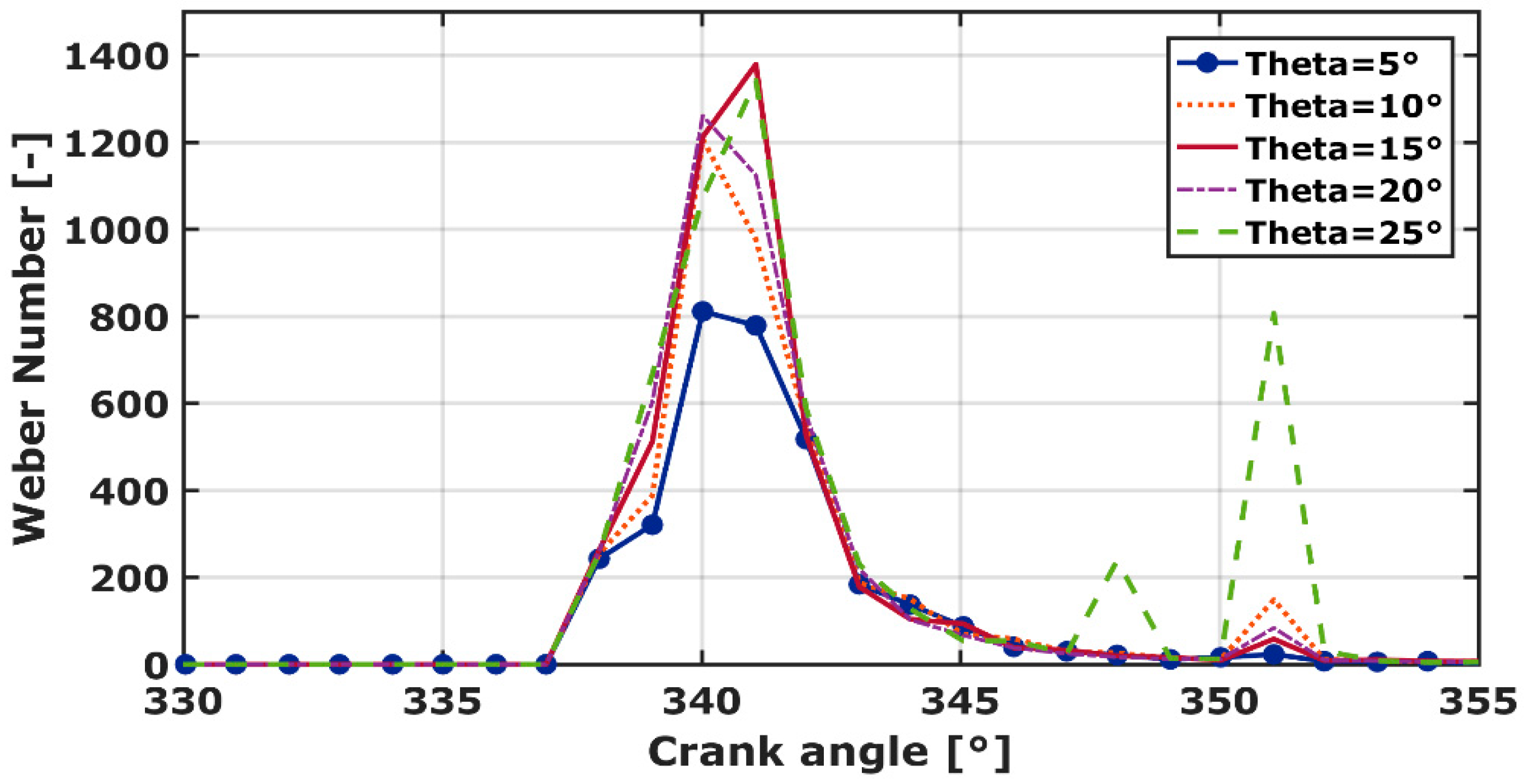
3.5. Weber Number (We)
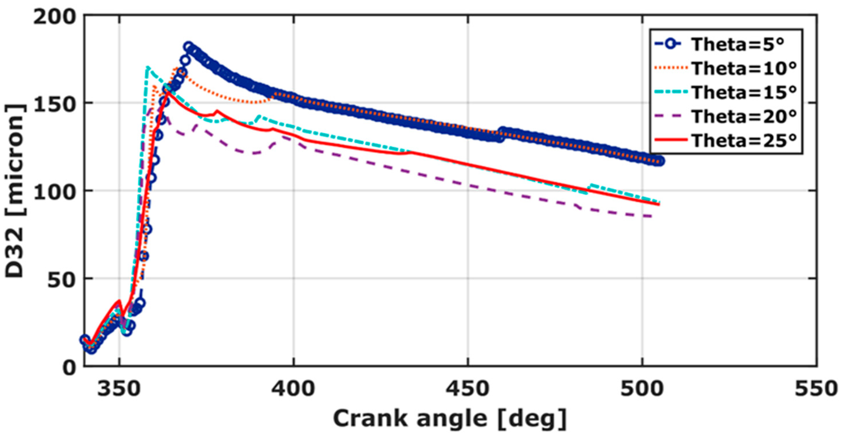
3.6. Sauter Mean Diameter (D32)
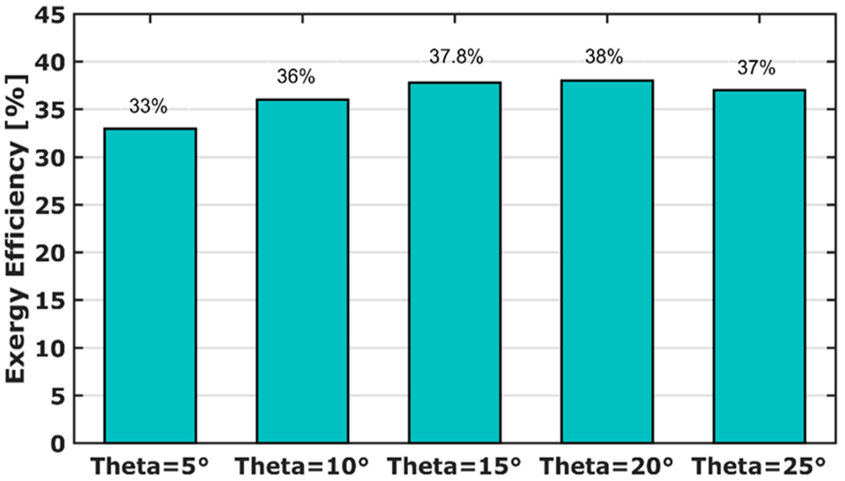
3.7. Exergy Efficiency
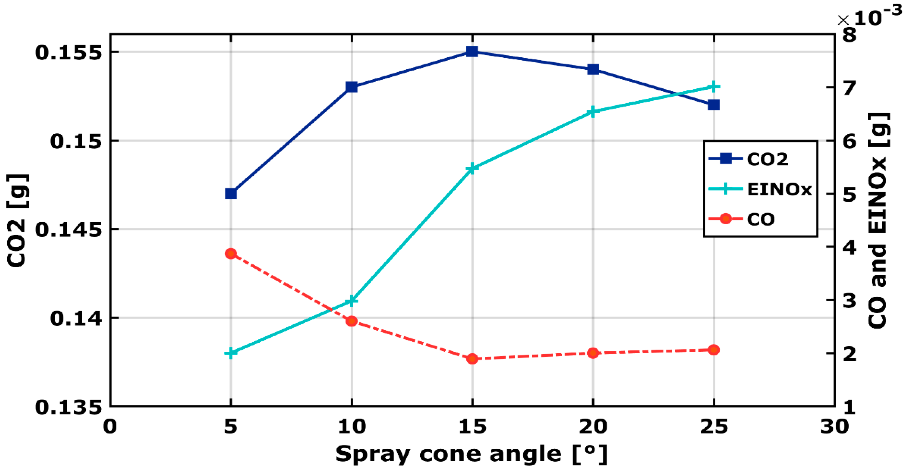
3.8. Output Species
4. Conclusions
- The choice of methane as a low reactive fuel serves to extend the combustion phasing, which enhances engine performances leading, thus, to a reduction of CO specie concentration.
- The spray cone angle has a significant impact on the heat transfer flux, pressure, temperature, and subsequent pollutants formation, as well.
- The combustion efficiency is remarkably improved for θ = 20°. This is registered by the temperature and pressure increase. At the mentioned spray angle, the pressure and the temperature equal 79.5 bar and 1766 K, respectively. They increase roughly by 11% and 6%, compared to the experimental work, carried out for θ = 10°. Following the outlined results, θ = 20° is assumed to be the best spray cone angle for combustion efficiency.
- In spite of the low emissions of CO2 and NOx for θ = 5°, the peak pressure at this angle is low (65 bar), this could be a limitation factor for the engine. The high CO emissions at Exhaust Valve Opening (EVO) indicate that the combustion was not complete.
- The optimal spray angle ranges between 15° and 20° for the best combustion performances and reduced species (CO, CO2, and NOx). For θ < 15°, the pressure decreases, and the combustion is not complete. For θ > 20°, NOx emissions are remarkably larger than θ = 10°. It increases by 58% compared to the experimental work.
- The results of exergy analysis show a maximum value of exergy efficiency for , which represent an increase of roughly 5%, compared to experimental work, at θ = 10°.
Author Contributions
Funding
Institutional Review Board Statement
Informed Consent Statement
Data Availability Statement
Acknowledgments
Conflicts of Interest
Nomenclature
| RCCI | Reactivity Controlled Combustion Ignition |
| RNG | Re-Normalization Group |
| HRR | Heat Release Rate |
| SMD,D32 | Sauter Mean Diameter |
| EVO | Exhaust Valve Opening |
| IVC | Intake Valve closing |
| KH-RT | Kelvin-Helmholtz-Rayleigh Taylor |
| ICE | Internal Combustion Engine |
| IC | Internal Combustion |
| CI | Compression Ignition |
| LTC | Low Temperature Combustion |
| CO2 | Carbon Dioxide |
| CO | Carbon Monoxide |
| NOx | Nitric Oxides |
| EINOx | Emissions Index Nitrogen Oxides |
| HCCI | Homogeneous Charge Compression Ignition |
| PCCI | Partially Compression Combustion Ignition |
| LPDDI | Low Pressure Dual-fuel Direct Injection |
| CA | Crank Angle |
| TDC | Top Dead Center |
| ATDC | After Top Dead Center |
| BTDC | Before Top Dead center |
| CH4 | Methane |
| TIVC | Inlet Valve Closing Temperature |
| HCB | Hydrogenated-Catalytic |
| UHC | Unburned Hydrocarbon |
| RANS | Reynolds Averaged Navier-Stokes |
| ER | Equivalence Ratio |
| EGR | Exhaust Gas Recirculation |
| CFD | Computational Fluid Dynamics |
| C7H16 | Heptane |
| C14H30 | Dodecane |
| Θ | Spray cone angle [°] |
| CP | Combustion Phasing |
References
- Rassoulinejad-Mousavi, S.M.; Mao, Y.; Zhang, Y. Reducing greenhouse gas emissions in Sandia methane-air flame by using a biofuel. Renew. Energy 2018, 128, 313–323. [Google Scholar] [CrossRef]
- Morsli, S.; Sabeur, A.; El Ganaoui, M.; Ramenah, H. Computational Simulation of Entropy Generation in a Combustion Chamber Using a Single Burner. Entropy 2018, 20, 922. [Google Scholar] [CrossRef] [PubMed] [Green Version]
- Duraisamy, G.; Rangasamy, M.; Govindan, N. A comparative study on methanol/diesel and methanol/PODE dual fuel RCCI combustion in an automotive diesel engine. Renew. Energy 2020, 145, 542–556. [Google Scholar] [CrossRef]
- Singh, A.; Saxena, M.R.; Maurya, R.K. Investigation of bifurcations in cyclic combustion dynamics of a CNG-diesel RCCI engine. Fuel 2022, 320, 123871. [Google Scholar] [CrossRef]
- Yao, M.; Zheng, Z.; Liu, H. Progress and recent trends in homogeneous charge compression ignition (HCCI) engines. Prog. Energy Combust. Sci. 2009, 35, 398–437. [Google Scholar] [CrossRef]
- Hunicz, J.; Medina, A.; Litak, G.; Curto-Risso, P.L.; Guzmán-Vargas, L. Effects of Direct Fuel Injection Strategies on Cycle-by-Cycle Variability in a Gasoline Homogeneous Charge Compression Ignition Engine: Sample Entropy Analysis. Entropy 2015, 17, 539–559. [Google Scholar] [CrossRef] [Green Version]
- Hadia, F.; Wadhah, S.; Ammar, H.; Ahmed, O. A Computational Study into the Effect of Design Parameters on Ignition Timing and Emission Characteristics of HCCI Engine in Internal Combustion Engines Fuelled with Isooctane. Int. J. Mech. Aerospace Ind. Mechatron. Manuf. Eng. 2016, 10, 224–231. [Google Scholar] [CrossRef]
- Dempsey, A.B.; Walker, N.R.; Gingrich, E.; Reitz, R.D. Comparison of Low Temperature Combustion Strategies for Advanced Compression Ignition Engines with a Focus on Controllability. Combust. Sci. Technol. 2014, 186, 210–241. [Google Scholar] [CrossRef]
- Paykani, A.; Garcia, A.; Shahbakhti, M.; Rahnama, P.; Reitz, R.D. Reactivity controlled compression ignition engine: Pathways towards commercial viability. Appl. Energy 2021, 282, 116174. [Google Scholar] [CrossRef]
- Reitz, R.D.; Duraisamy, G. Review of high efficiency and clean reactivity controlled compression ignition (RCCI) combustion in internal combustion engines. Prog. Energy Combust. Sci. 2015, 46, 12–71. [Google Scholar] [CrossRef] [Green Version]
- Yousefi, A.; Birouk, M.; Guo, H. An experimental and numerical study of the effect of diesel injection timing on natural gas/diesel dual-fuel combustion at low load. Fuel 2017, 203, 642–657. [Google Scholar] [CrossRef]
- Yang, B.; Duan, Q.; Liu, B.; Zeng, K. Parametric investigation of low pressure dual-fuel direct injection on the combustion performance and emissions characteristics in a RCCI engine fueled with diesel and CH4. Fuel 2020, 260, 116408. [Google Scholar] [CrossRef]
- Poorghasemi, K.; Saray, R.K.; Ansari, E.; Irdmousa, B.K.; Shahbakhti, M.; Naber, J.D. Effect of diesel injection strategies on natural gas/diesel RCCI combustion characteristics in a light duty diesel engine. Appl. Energy 2017, 199, 430–446. [Google Scholar] [CrossRef]
- Liu, J.; Wang, J.; Zhao, H. Optimization of the injection parameters and combustion chamber geometries of a diesel/natural gas RCCI engine. Energy 2018, 164, 837–852. [Google Scholar] [CrossRef]
- Hasankola, S.S.M.; Shafaghat, R.; Jahanian, O.; Amiri, S.T.; Shooghi, M. Numerical investigation of the effects of inlet valve closing temperature and exhaust gas recirculation on the performance and emissions of an RCCI engine. J. Therm. Anal. 2020, 139, 2465–2474. [Google Scholar] [CrossRef]
- Jiang, P.; Liu, X.; Cao, L.; Wang, Q.; He, Z. Numerical investigation of dual-fuel direct injection on RCCI combustion performance at low load condition. J. Mech. Sci. Technol. 2021, 35, 4247–4259. [Google Scholar] [CrossRef]
- Zhu, L.; Qian, Y.; Wang, X.; Lu, X. Effects of direct injection timing and premixed ratio on combustion and emissions characteristics of RCCI (Reactivity Controlled Compression Ignition) with N-heptane/gasoline-like fuels. Energy 2015, 93, 383–392. [Google Scholar] [CrossRef]
- Dempsey, A.B.; Walker, N.R.; Reitz, R.D. Effect of Cetane Improvers on Gasoline, Ethanol, and Methanol Reactivity and the Implications for RCCI Combustion. SAE Int. J. Fuels Lubr. 2013, 6, 170–187. [Google Scholar] [CrossRef]
- Mohammadnejad, S.; Amani, E.; Hosseini, R.; Chitsaz, I.; Kamali, A. Effects of the swirl ratio and spray angle on the mixture stratification in a diesel–NG RCCI engine. J. Braz. Soc. Mech. Sci. Eng. 2019, 41, 233. [Google Scholar] [CrossRef]
- Splitter, D.; Wissink, M.; Kokjohn, S.; Reitz, R.D. Effect of Compression Ratio and Piston Geometry on RCCI Load Limits and Efficiency. In Proceedings of the SAE 2012 World Congress & Exhibition, Detroit, MI, USA, 24–26 April 2012. [Google Scholar] [CrossRef]
- Lee, S.; Park, S. Optimization of the piston bowl geometry and the operating conditions of a gasoline-diesel dual-fuel engine based on a compression ignition engine. Energy 2017, 121, 433–448. [Google Scholar] [CrossRef]
- Kakaee, A.-H.; Rahnama, P.; Paykani, A. Influence of fuel composition on combustion and emissions characteristics of natural gas/diesel RCCI engine. J. Nat. Gas Sci. Eng. 2015, 25, 58–65. [Google Scholar] [CrossRef]
- Li, Y.; Jia, M.; Chang, Y.; Xie, M.; Reitz, R.D. Towards a comprehensive understanding of the influence of fuel properties on the combustion characteristics of a RCCI (reactivity controlled compression ignition) engine. Energy 2016, 99, 69–82. [Google Scholar] [CrossRef]
- Ries, F.; Li, Y.; Nishad, K.; Janicka, J.; Sadiki, A. Entropy Generation Analysis and Thermodynamic Optimization of Jet Impingement Cooling Using Large Eddy Simulation. Entropy 2019, 21, 129. [Google Scholar] [CrossRef] [PubMed] [Green Version]
- Ganjehkaviri, A.; Jaafar, M.N.M. Energy Analysis and Multi-Objective Optimization of an Internal Combustion Engine-Based CHP System for Heat Recovery. Entropy 2014, 16, 5633–5653. [Google Scholar] [CrossRef] [Green Version]
- Ge, Y.; Chen, L.; Sun, F. Progress in Finite Time Thermodynamic Studies for Internal Combustion Engine Cycles. Entropy 2016, 18, 139. [Google Scholar] [CrossRef] [Green Version]
- Zhang, J.; Huang, Z.; Han, D. Effects of mechanism reduction on the exergy losses analysis in n-heptane autoignition processes. Int. J. Engine Res. 2020, 21, 1764–1777. [Google Scholar] [CrossRef]
- Kooshkbaghi, M.; Frouzakis, C.E.; Boulouchos, K.; Karlin, I.V. Entropy production analysis for mechanism reduction. Combust. Flame 2014, 161, 1507–1515. [Google Scholar] [CrossRef]
- Kong, S.-C.; Reitz, R.D. Application of detailed chemistry and CFD for predicting direct injection HCCI engine combustion and emissions. Proc. Combust. Inst. 2002, 29, 663–669. [Google Scholar] [CrossRef]
- Kong, S.-C.; Marriott, C.D.; Reitz, R.D.; Christensen, M. Modeling and Experiments of HCCI Engine Combustion Using Detailed Chemical Kinetics with Multidimensional CFD. SAE Tech. Pap. 2001. [Google Scholar] [CrossRef]
- Puduppakkam, K.V.; Liang, L.; Naik, C.V.; Meeks, E.; Kokjohn, S.L.; Reitz, R.D. Use of Detailed Kinetics and Advanced Chemistry-Solution Techniques in CFD to Investigate Dual-Fuel Engine Concepts. SAE Int. J. Engines 2011, 4, 1127–1149. [Google Scholar] [CrossRef]
- Yakhot, V.; Orszag, S.A. Renormalization group analysis of turbulence. I. Basic theory. J. Sci. Comput. 1986, 1, 3–51. [Google Scholar] [CrossRef]
- Tan, Z.; Reitz, R. Multi-Dimensional Modeling of Ignition and Combustion in Premixed and DIS/CI (Direct Injection Spark/Compression Ignition) Engines; University of Wisconsin-Madison: Madison, WI, USA, 2003. [Google Scholar]
- Han, Z.; Reitz, R.D. Turbulence Modeling of Internal Combustion Engines Using RNG κ-ε Models. Combust. Sci. Technol. 1995, 106, 267–295. [Google Scholar] [CrossRef]
- Beale, J.; Reitz, R. Modeling Spray Atomization with the KH-RT Hybrid Model. At. Sprays 1999, 9, 623–650. [Google Scholar]
- Sanli, B.G.; Özcanli, M.; Serin, H. Assessment of thermodynamic performance of an IC engine using microalgae biodiesel at various ambient temperatures. Fuel 2020, 277, 118108. [Google Scholar] [CrossRef]
- Bhatti, S.; Verma, S.; Tyagi, S. Energy and exergy based performance evaluation of variable compression ratio spark ignition engine based on experimental work. Therm. Sci. Eng. Prog. 2019, 9, 332–339. [Google Scholar] [CrossRef]
- Krishnamoorthi, M.; Malayalamurthi, R. Availability analysis, performance, combustion and emission behavior of bael oil—Diesel—Diethyl ether blends in a variable compression ratio diesel engine. Renew. Energy 2018, 119, 235–252. [Google Scholar] [CrossRef]
- Sahoo, B.B.; Saha, U.K.; Sahoo, N. Diagnosing the effects of pilot fuel quality on exergy terms in a biogas run dual fuel diesel engine. Int. J. Exergy 2012, 10, 77–93. [Google Scholar] [CrossRef]
- Nieman, D.E.; Dempsey, A.B.; Reitz, R.D. Heavy-Duty RCCI Operation Using Natural Gas and Diesel. SAE Int. J. Engines 2012, 5, 270–285. [Google Scholar] [CrossRef]
- Balijepalli, R.; Kumar, A.; Rajak, U.; Elkotb, M.A.; Alwetaishi, M.; Reddy, S.K.; Dasore, A.; Verma, T.N.; Saleel, C.A.; Afzal, A. Numerical investigation of the effect of spray angle on emission characteristics of a diesel engine fueled with natural gas and diesel. Energy Rep. 2021, 7, 7273–7287. [Google Scholar] [CrossRef]
- Ağbulut, Ü.; Karagöz, M.; Sarıdemir, S.; Öztürk, A. Impact of various metal-oxide based nanoparticles and biodiesel blends on the combustion, performance, emission, vibration and noise characteristics of a CI engine. Fuel 2020, 270, 117521. [Google Scholar] [CrossRef]
- Kokjohn, S.L.; Hanson, R.M.; Splitter, D.; Reitz, R.D. Fuel reactivity controlled compression ignition (RCCI): A pathway to controlled high-efficiency clean combustion. Int. J. Engine Res. 2011, 12, 209–226. [Google Scholar] [CrossRef]
- Naber, J.; Reitz, R.D. Modeling Engine Spray/Wall Impingement. SAE Techn. Paper Ser. 1988, 22, 880107. [Google Scholar]
- Takeno, T.; Nishioka, M. Species conservation and emission indices for flames described by similarity solutions. Combust. Flame 1993, 92, 465–468. [Google Scholar] [CrossRef]
- Tomić, M.; Savin, L.; Simikić, M.; Kiss, F.; Kešelj, K.; Ivanišević, M.; Ponjičan, O.; Zoranović, M.; Sedlar, A. Effects of biodiesel on changes in IC engine performances: A long-term experiment with farm tractors. Fuel 2021, 292, 120300. [Google Scholar] [CrossRef]


| Parameter | Value |
|---|---|
| Engine type | Caterpillar 3400 |
| Bore × stroke [mm] | 137.2 × 165.1 |
| Connecting rod length [mm] | 261.62 |
| Displacement volume [L] | 2.44 |
| Compression ratio [-] | 16.25 |
| Nozzle type (hole × diameter) [mm] | 6 × 0.23 |
| Diesel fuel injection type | Direct injection |
| Natural gas injection type | Direct injection |
| Boundary and Initial Condition | Value |
|---|---|
| Combustion chamber temperature at IVC [K] | 360 |
| Combustion chamber pressure at IVC [bar] | 1.02 |
| Kinetic energy [J] | 10 |
| Turbulence dissipation rate [m2/s3] | 1732 |
| Cylinder head wall temperature [K] | 400 |
| Piston temperature [K] | 400 |
| Liner wall temperature [K] | 400 |
| Turbulence model | k-ε RNG |
| Spray model | KH-RT |
| Injector type | Solid cone |
| LHV (MJ/kg) | (kg/h) | Inlet Temperature (K) | ||
|---|---|---|---|---|
| Diesel | 5.7 | 44.643 | 0.4503 | 298.15 |
| Methane | 18.075 | 50 | 1.259 |
| (kW) | 7.911 | 8.573 | 9.003 | 9.013 | 8.816 |
Publisher’s Note: MDPI stays neutral with regard to jurisdictional claims in published maps and institutional affiliations. |
© 2022 by the authors. Licensee MDPI, Basel, Switzerland. This article is an open access article distributed under the terms and conditions of the Creative Commons Attribution (CC BY) license (https://creativecommons.org/licenses/by/4.0/).
Share and Cite
Hamdi, F.; Agrebi, S.; Idrissi, M.S.; Mondo, K.; Labiadh, Z.; Sadiki, A.; Chrigui, M. Impact of Spray Cone Angle on the Performances of Methane/Diesel RCCI Engine Combustion under Low Load Operating Conditions. Entropy 2022, 24, 650. https://doi.org/10.3390/e24050650
Hamdi F, Agrebi S, Idrissi MS, Mondo K, Labiadh Z, Sadiki A, Chrigui M. Impact of Spray Cone Angle on the Performances of Methane/Diesel RCCI Engine Combustion under Low Load Operating Conditions. Entropy. 2022; 24(5):650. https://doi.org/10.3390/e24050650
Chicago/Turabian StyleHamdi, Fathi, Senda Agrebi, Mohamed Salah Idrissi, Kambale Mondo, Zeineb Labiadh, Amsini Sadiki, and Mouldi Chrigui. 2022. "Impact of Spray Cone Angle on the Performances of Methane/Diesel RCCI Engine Combustion under Low Load Operating Conditions" Entropy 24, no. 5: 650. https://doi.org/10.3390/e24050650
APA StyleHamdi, F., Agrebi, S., Idrissi, M. S., Mondo, K., Labiadh, Z., Sadiki, A., & Chrigui, M. (2022). Impact of Spray Cone Angle on the Performances of Methane/Diesel RCCI Engine Combustion under Low Load Operating Conditions. Entropy, 24(5), 650. https://doi.org/10.3390/e24050650