
Higher-Order Belief Propagation Correction Decoder for Polar Codes


Abstract
:1. Introduction
- Different from using the stopping tree to reduce the searching range in the original BPC decoder, a new metric is proposed, which combines the reliability of code bits and the size of the stopping tree to which it belongs, to construct the correction set effectively.
- We refine the correction operation in the original BPC decoder. Setting a threshold , an identified code bit is only corrected to its opposite side when its reliability is lower than . The decoding latency is reduced by avoiding invalid decoding attempts, especially in low signal-to-noise ratio (SNR) regions. In addition, the refresh operation is modified by re-initializing the massage to the initial state of the original BP rather than the end state to remove the dispensable store procedures.
- The MBPC- decoder is proposed to further improve the BLER performance, where the decoder is executed on correction sets of increasing order. The correction set , in which each element contains code bits, is established nested based on the preorder set and the corresponding decoding result.
2. Preliminaries
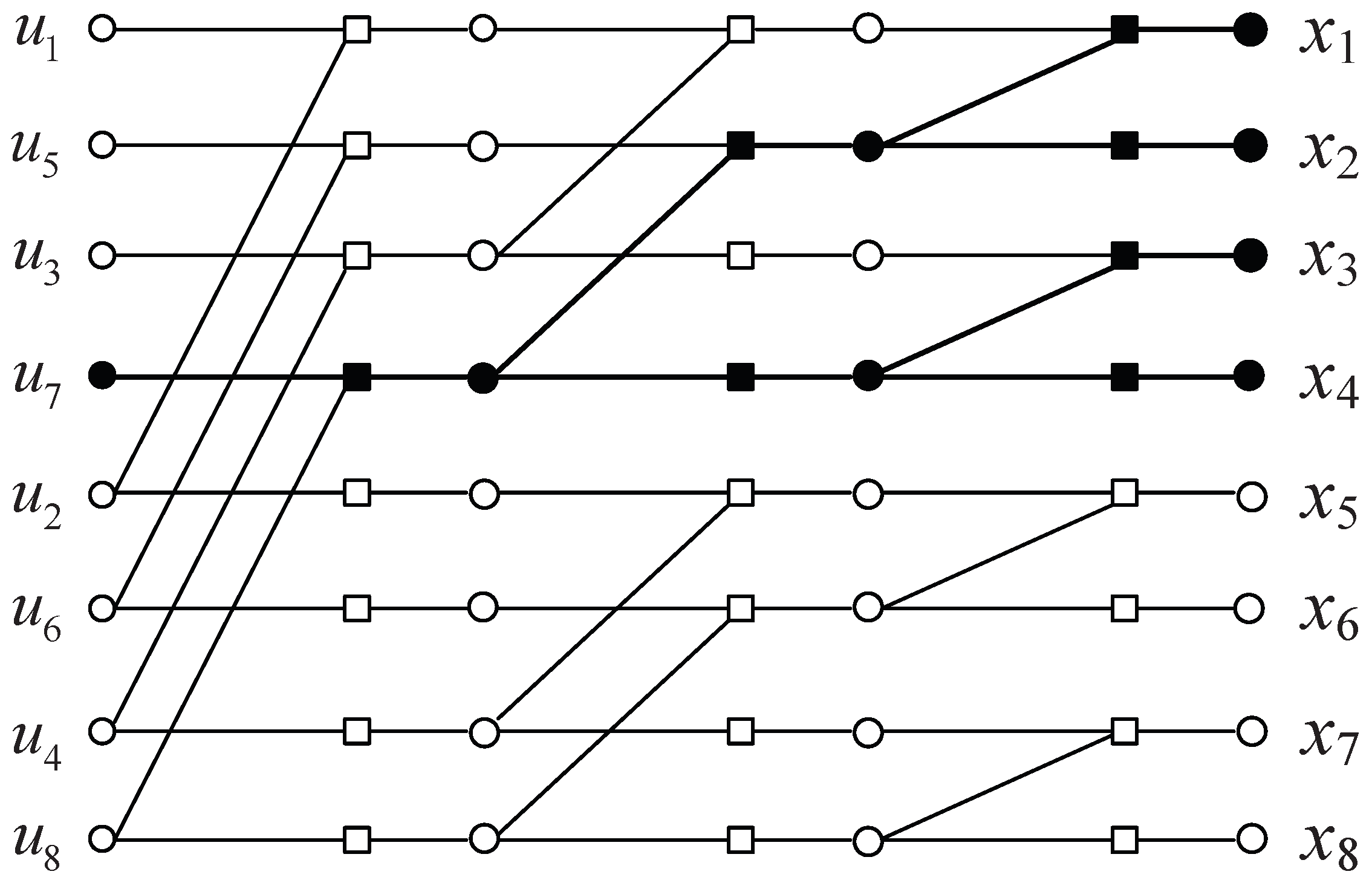
2.1. Polar Codes
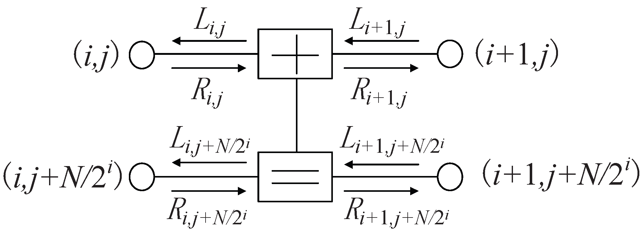
2.2. Belief Propagation Decoder
2.3. Belief Propagation Correction Decoder
| Algorithm 1 The BPC decoding algorithm. |
Input:
, , T, .
|
3. Design of Higher-Order Belief Propagation Correction Decoder
3.1. A Metric to Establish the Correction Set
3.2. The Modified BPC Decoder
| Algorithm 2 Modified BPC decoding algorithm. |
Input:, , , T.
|
3.3. Higher-Order Belief Propagation Correction Decoder
| Algorithm 3 The procedure of . |
|
| Algorithm 4 The proposed MBPC- decoding algorithm. |
Input:, , , T, .
|
| Algorithm 5 The procedure of . |
|
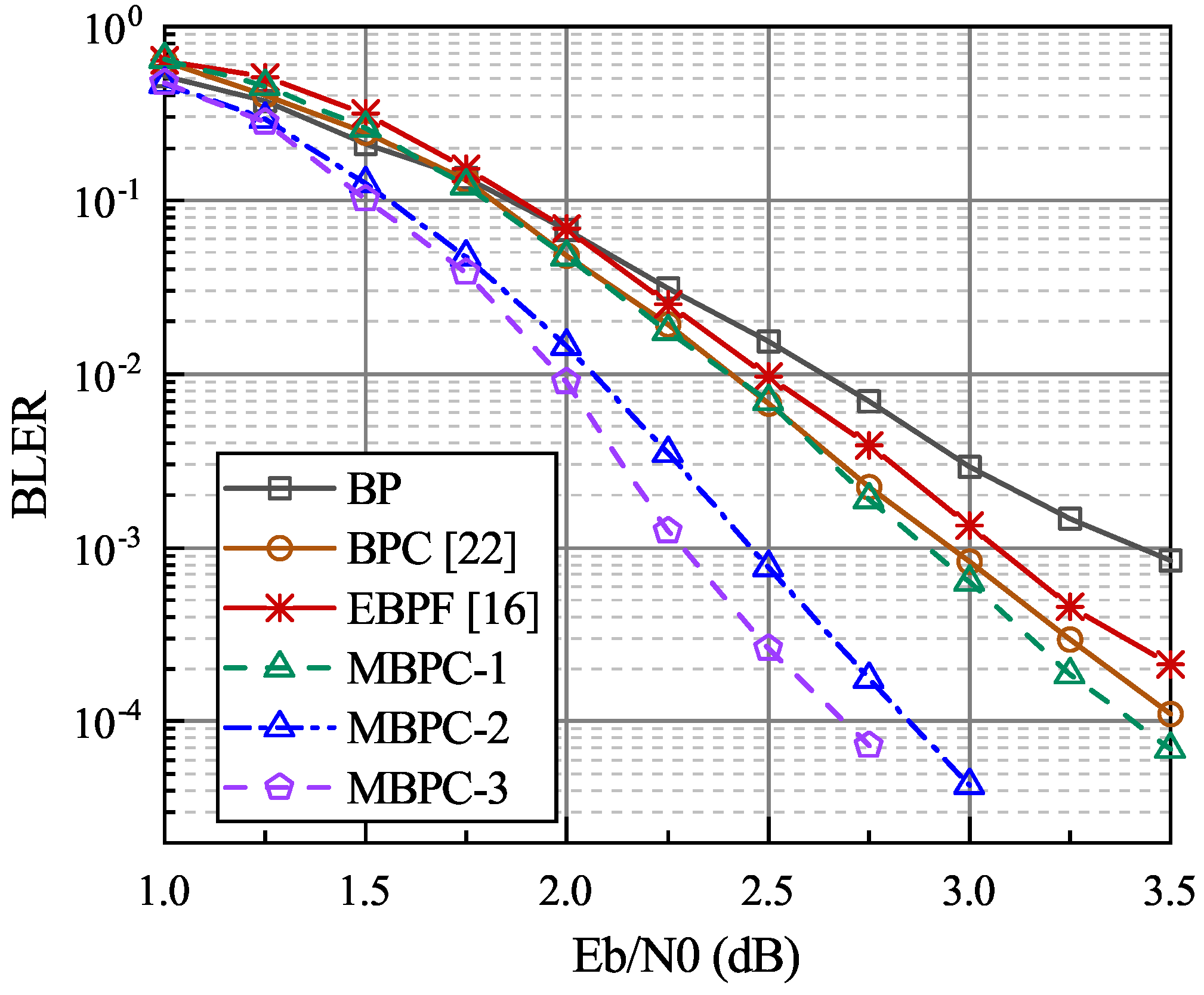
4. Numerical Results
5. Conclusions
Author Contributions
Funding
Institutional Review Board Statement
Informed Consent Statement
Data Availability Statement
Conflicts of Interest
References
- Arıkan, E. Channel polarization: A method for constructing capacity-achieving codes for symmetric binary-input memoryless channels. IEEE Trans. Inf. Theory 2009, 55, 3051–3073. [Google Scholar] [CrossRef]
- Final Report of 3GPP TSG RAN WG1 #87 v1.0.0; Reno, NV, USA. November 2016. Available online: https://www.3gpp.org/ftp/tsg_ran/WG1_RL1/TSGR1_87/Report/Final_Minutes_report_RAN1%2387_v100.zip (accessed on 10 November 2021).
- Tal, I.; Vardy, A. List Decoding of Polar Codes. IEEE Trans. Inf. Theory 2015, 61, 2213–2226. [Google Scholar] [CrossRef]
- Niu, K.; Chen, K. CRC-Aided Decoding of Polar Codes. IEEE Commun. Lett. 2012, 16, 1668–1671. [Google Scholar] [CrossRef]
- Arıkan, E. Polar Codes: A Pipelined Implementation. In Proceedings of the 4th International Symposium on Broadband Communication (ISBC 2010), Melaka, Malaysia, 11–14 July 2010; pp. 1–3. [Google Scholar]
- Arıkan, E. A performance comparison of polar codes and reed-muller codes. IEEE Commun. Lett. 2008, 12, 447–449. [Google Scholar] [CrossRef]
- Elkelesh, A.; Ebada, M.; Cammerer, S.; Brink, S.T. Mitigating clipping effects on error floors under belief propagation decoding of polar codes. In Proceedings of the 2017 International Symposium on Wireless Communication Systems (ISWCS), Bologna, Italy, 28–31 August 2017; pp. 384–389. [Google Scholar]
- Doan, N.; Hashemi, S.A. On the decoding of polar codes on permuted factor graphs. In Proceedings of the 2018 IEEE Global Communications Conference (GLOBECOM), Abu Dhabi, United Arab Emirates, 9–13 December 2018; pp. 1–6. [Google Scholar]
- Li, L.; Liu, L. Belief propagation with permutated graphs of polar codes. IEEE Access 2020, 8, 17632–17641. [Google Scholar] [CrossRef]
- Ranasinghe, V.; Rajatheva, N. Partially permuted multi-trellis belief propagation for polar codes. In Proceedings of the 2020 IEEE International Conference on Communications (ICC), Dublin, Ireland, 7–11 June 2020; pp. 1–6. [Google Scholar]
- Elkelesh, A.; Ebada, M.; Cammerer, S.; Brink, S.T. Belief propagation list decoding of polar codes. IEEE Commun. Lett. 2018, 22, 1536–1539. [Google Scholar] [CrossRef] [Green Version]
- Ren, Y.; Shen, Y.; Zhang, Z.; You, X. Efficient belief propagation polar decoder with loop simplification based factor graphs. IEEE Trans. Veh. Technol. 2020, 69, 5657–5660. [Google Scholar] [CrossRef]
- Sun, S.; Cho, S.G.; Zhang, Z. Post-processing methods for improving coding gain in belief propagation decoding of polar codes. In Proceedings of the IEEE Global Communications Conference (GLOBECOM), Singapore, 4–8 December 2017; pp. 1–6. [Google Scholar]
- Arlı, A.C.; Gazi, O. Noise-aided belief propagationlist decoding of polar codes. IEEE Commun. Lett. 2019, 23, 1285–1288. [Google Scholar] [CrossRef]
- Yu, Y.; Pan, Z.; Liu, N.; You, X. Belief propagation bit-flip decoder for polar codes. IEEE Access 2019, 7, 10937–10946. [Google Scholar] [CrossRef]
- Shen, Y.; Song, W.; Ren, Y.; Ji, H.; You, X.; Zhang, C. Enhanced belief propagation decoder for 5G polar codes with bit-flipping. IEEE Trans. Circuits Syst. II Exp. Briefs 2020, 67, 901–905. [Google Scholar]
- Shen, Y.; Song, W.; Ji, H. Improved Belief Propagation Polar Decoders With Bit-Flipping Algorithms. IEEE Trans. Commun. 2020, 68, 6699–6713. [Google Scholar] [CrossRef]
- Zhang, J.; Wang, M. Belief Propagation Decoder With Multiple Bit-Flipping Sets and Stopping Criteria for Polar Codes. IEEE Access 2020, 8, 83710–83717. [Google Scholar] [CrossRef]
- Teng, C.; Yeu, A.; Wu, A. Convolutional neural network-aided tree-based bit-flipping framework for polar decoder using imitation learning. IEEE Trans. Signal Process. 2020, 69, 300–313. [Google Scholar] [CrossRef]
- Yang, Y.; Yin, C.; Jan, Q.; Hu, Y.; Pan, Z.; Liu, N.; You, X. Noise-aided belief propagation list bit-flip decoder for polar codes. In Proceedings of the 2020 International Conference on Wireless Communications and Signal Processing(WCSP), Wuhan, China, 21–23 October 2020; pp. 807–810. [Google Scholar]
- Feng, B.; Liu, R.; Tian, K. A Novel Post-Processing Method for Belief Propagation List Decoding of Polar Codes. IEEE Commun. Lett. 2021, 25, 2468–2471. [Google Scholar] [CrossRef]
- Zhang, M.; Li, Z.; Xing, L. An Enhanced Belief Propagation Decoder for Polar Codes. IEEE Commun. Lett. 2021, 25, 3161–3165. [Google Scholar] [CrossRef]
- Hussami, N.; Korada, S.B.; Urbanke, R. Performance of polar codes for channel and source coding. In Proceedings of the IEEE International Symposium on Information Theory (ISIT), Seoul, Korea, 28 June–3 July 2009; pp. 1488–1492. [Google Scholar]
- Eslami, A.; Pishro-Nik, H. On bit error rate performance of polar codes in finite regime. In Proceedings of the 48th Annual Allerton Conference on Communication, Control, and Computing(Allerton), Monticello, IL, USA, 29 September–1 October 2010; pp. 188–194. [Google Scholar]
- Eslami, A.; Pishro-Nik, H. A practical approach to polar codes. In Proceedings of the IEEE International Symposium on Information Theory (ISIT), Saint Petersburg, Russia, 31 July–5 August 2011; pp. 16–20. [Google Scholar]
- Chandesris, L.; Savin, V.; Declercq, D. An improved SCFlip decoder for polar codes. In Proceedings of the 2016 IEEE Global Communications Conference (GLOBECOM), Washington, DC, USA, 4–8 December 2016; pp. 1–6. [Google Scholar]
- Hashemi, S.A.; Condo, C.; Gross, W.J. Fast and Flexible Successive-Cancellation List Decoders for Polar Codes. IEEE Trans. Signal Process. 2017, 65, 5756–5769. [Google Scholar] [CrossRef] [Green Version]


| Decoder | SNR (dB) | ||||||
| 1.5 | 1.75 | 2.0 | 2.25 | 2.5 | 2.75 | 3.0 | |
| MBPC-1 | 3080 | 946 | 396 | 220 | 165 | 133 | 115 |
| MBPC-2 | 15,466 | 3476 | 924 | 396 | 212 | 154 | 121 |
| List size | |||||||
| CA-SCL | |||||||
| 5142 | 5142 | ||||||
Publisher’s Note: MDPI stays neutral with regard to jurisdictional claims in published maps and institutional affiliations. |
© 2022 by the authors. Licensee MDPI, Basel, Switzerland. This article is an open access article distributed under the terms and conditions of the Creative Commons Attribution (CC BY) license (https://creativecommons.org/licenses/by/4.0/).
Share and Cite
Zhang, M.; Li, Z.; Xing, L.; Liao, X. Higher-Order Belief Propagation Correction Decoder for Polar Codes. Entropy 2022, 24, 534. https://doi.org/10.3390/e24040534
Zhang M, Li Z, Xing L, Liao X. Higher-Order Belief Propagation Correction Decoder for Polar Codes. Entropy. 2022; 24(4):534. https://doi.org/10.3390/e24040534
Chicago/Turabian StyleZhang, Meng, Zhuo Li, Lijuan Xing, and Xin Liao. 2022. "Higher-Order Belief Propagation Correction Decoder for Polar Codes" Entropy 24, no. 4: 534. https://doi.org/10.3390/e24040534
APA StyleZhang, M., Li, Z., Xing, L., & Liao, X. (2022). Higher-Order Belief Propagation Correction Decoder for Polar Codes. Entropy, 24(4), 534. https://doi.org/10.3390/e24040534