Skip to Content
  • Article
  • Open Access

10 November 2014

Heat Transfer Characteristics of a Speaker Using Nano-Sized Ferrofluid

and
1
Department of Mechanical Engineering, Dong-A University, Busan 604-714, Korea
2
Graduate school of Mechanical Engineering, Dong-A University, Busan 604-714, Korea
*
Author to whom correspondence should be addressed.

Abstract

The purpose of this article is to study the heat transfer characteristics of a voice-coil and permanent magnet for a speaker using nano-sized ferrofluid. In order to investigate the temperature characteristics of the speaker, the speaker power ratings, ambient temperatures of the test chamber, chamber sizes and input signals were tested. As a result, the temperatures of the voice-coil and magnet for the speaker increased with time due to the thermal linearity. The temperature of the voice-coil increased with the decrease of the input signals, but with the increase of the nominal power rating. The voice-coil temperature of Speaker 1 using ferrofluid of an amount of 650 μL at an elapsed time of 10,000 s was 24.5% lower than that of general Speaker 1. In addition, the proper size selection of the enclosure is an important design factor to ensure the sound quality and effective heat transfer of the speaker.

1. Introduction

Speakers were originally a sound device to transform electrical energy into sound energy using a voice-coil. The first speaker was the horn-type, developed by Ernst Siemens in Germany in the 1800s. Since then, many kinds of speakers have been developed to amplify sound. The structures and functions of speakers are very simple, but the shapes and sizes of speakers are rather various, depending on the usage and purpose. Speakers are generally comprised of a cone body for vibrating the sound, a dust cap, a basket, a spider, a bobbin, a top-plate, a voice-coil twisting around the bobbin for the purpose of generating the sound, a magnet (permanent magnet) to form the magnetic field and a bottom plate, as shown in Figure 1. Figure 1 shows the schematic of a general speaker [1] (pp. 40–118). Among many parts of the speaker, the voice-coil is an important part to make a qualified sound with the input signals of the current and to decide the overall sound performance and reliability. As the current as electrical energy is supplied to the voice-coil, the voice-coils twists around the bobbin, moving up and down along the bobbin, as shown in Figure 2. Then, the sound of the speaker is generated using the formation of a magnetic field, and heat is also generated by the electrical resistance of the voice-coil due to the thermal linearity [2].
Figure 1. Schematic of a general speaker.
Figure 2. The sound process of a general speaker.
Specifically: the generated heat of the speaker is the combined effect of three types of mechanisms: the vibration, the Joule effect at the voice-coil and the magnetic field [3]. The generated heat of the speaker causes a performance reduction with a sound quality decline, and the heat generated by the voice-coil brings about the burn out of and loosening problems for the speaker. Figure 2 shows the sound process of the voice-coil for speakers with an input signal.
Few studies on the heat transfer and temperature characteristics of a speaker have been published in the open literature. Hsu and Poornima [4] numerically studied the temperature prediction of the voice-coil of a moving coil loudspeaker. They analyzed the temperature characteristic of the voice-coil by computer simulation. Pan et al. [5] experimentally investigated the forced thermo-acoustic oscillation driven by a louder speaker. Koh et al. [6] reported the heat transfer model of a speaker whose voice-coil vibrates at a certain frequency, developed a CFD analysis and validated this with experimental results. Kim et al. [7] numerically investigated the heat transfer and voice-coil temperature characteristics of both ferrofluid and general speakers. The temperatures of voice-coils increased with a decrease of the input signals. Lee et al. [8] also simulated the temperature characteristics of the voice-coil for a ferrofluid woofer speaker with input signals. As a result, they reported that the temperature of the woofer speaker using ferrofluid was lower by 51.0% compared to a woofer speaker without ferrofluid.
However, experimental studies of the effects on the ferrofluid of the heat transfer of the voice-coil and permanent magnet for a speaker have been limited, although Lee and Yoo [9] investigated the damping effect and the improvement of the ferrofluid for a speaker. Therefore, the objective of this study is to investigate the heat transfer and temperature characteristics of the voice-coil and magnet for a speaker using nano-sized ferrofluid. In addition, the speakers are tested and compared under various conditions with the speaker power capacities, ambient temperatures, chamber sizes and input signals.

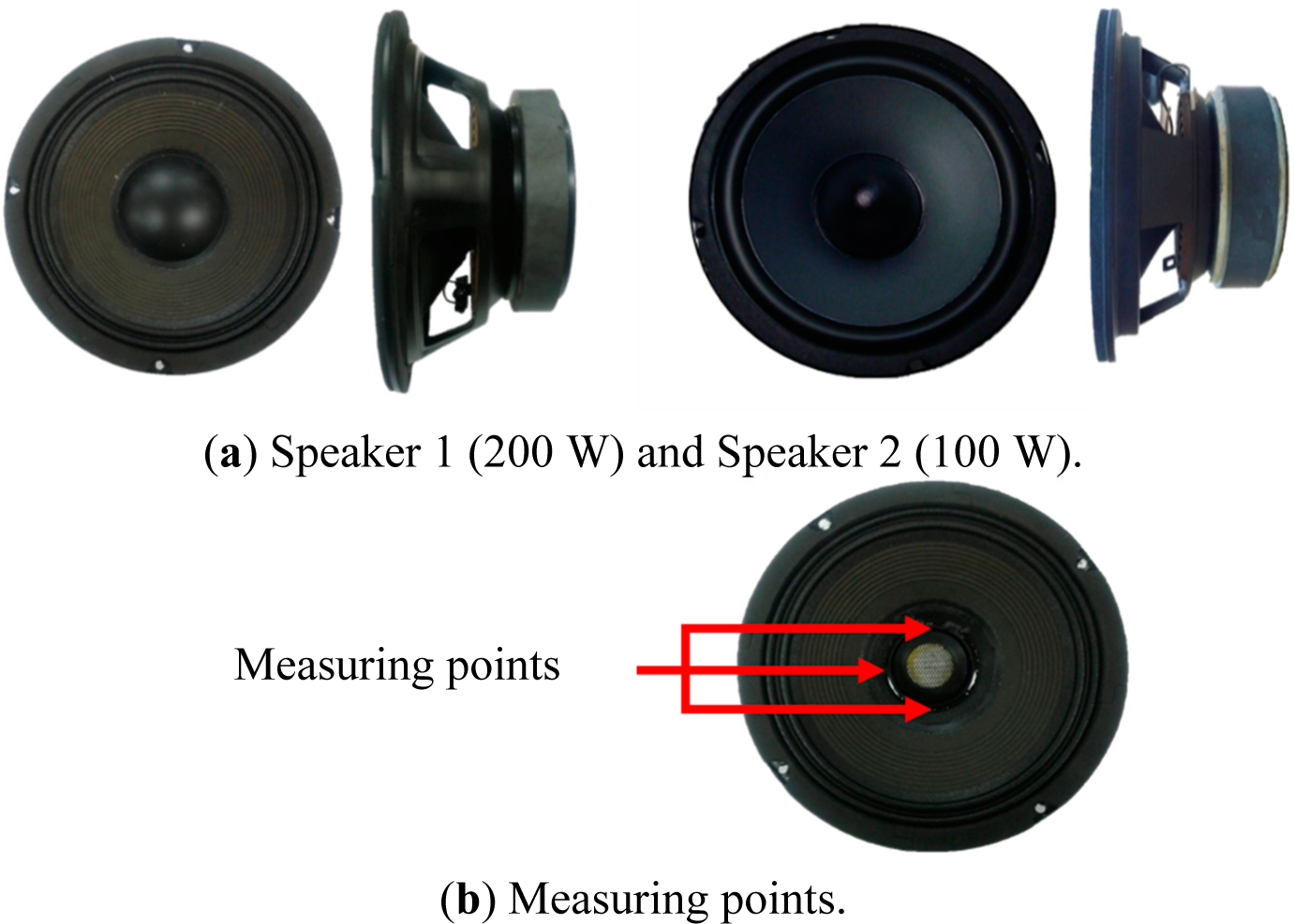
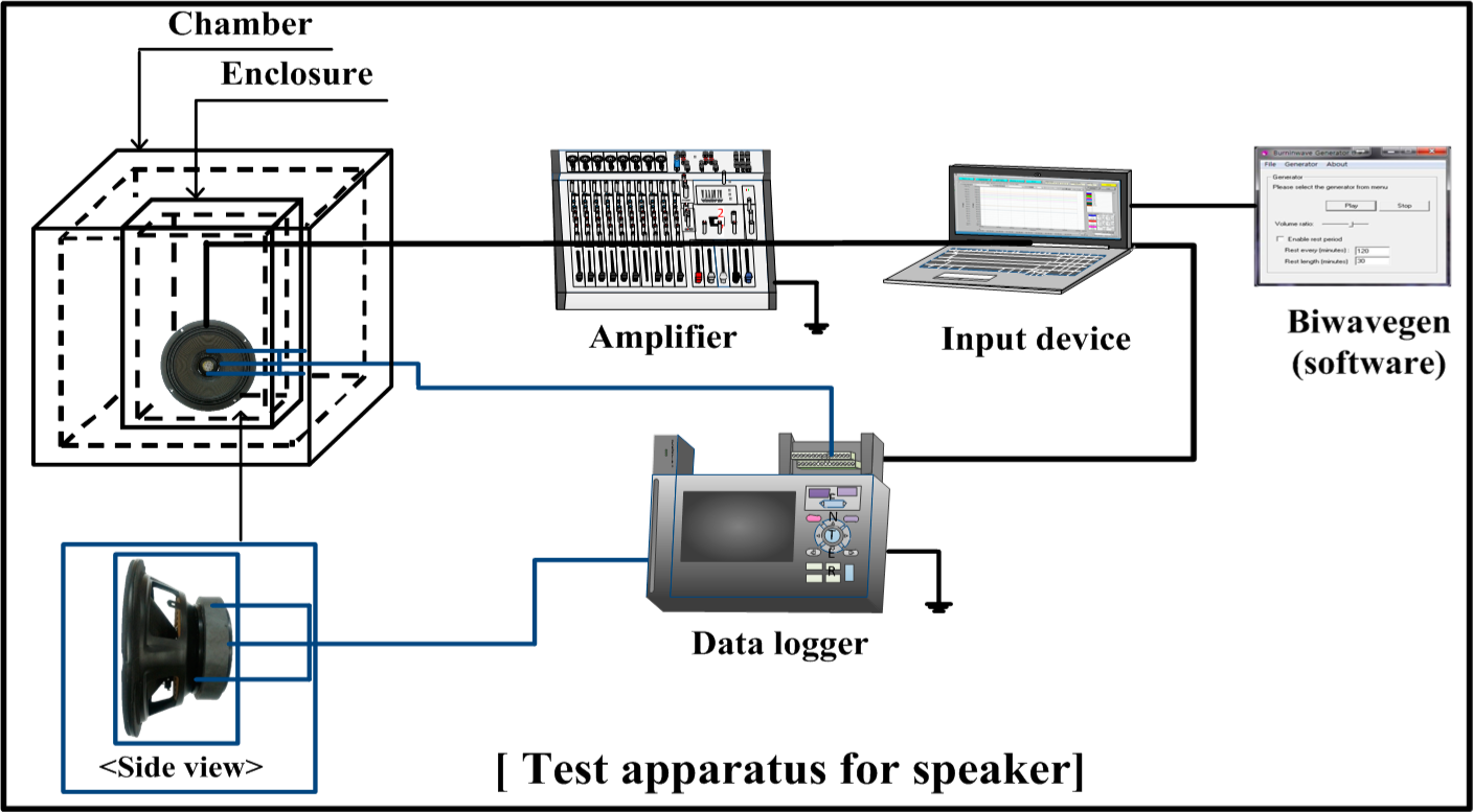
2. Experimental Setup and Data

Figure 3a shows the speakers used in this study. Two speakers were used with an allowable maximum input to output of 200 W (Speaker 1) and 100 W (Speaker 2). Figure 3b shows the measurement points of the temperatures of the tested speakers. Table 1 shows the specifications of the tested speakers. The nominal power ratings of Speaker 1 and Speaker 2 were 200 W and 100 W, respectively. The sizes of Speaker 1 with a diaphragm of 206.0 mm and Speaker 2 with a diaphragm of 165.0 mm are 206 (D) × 90 (H) mm and 165 (D) × 80 (H) mm, respectively.
Figure 3. Pictures of the tested speakers.
Table 1. Specifications of the speakers.
The diameters of the voice-coil were 38.5 mm for Speaker 1 and 30.5 mm for Speaker 2, respectively. The impedances and the sound pressure levels were 8.0 Ω with an accuracy of ±1.2 Ω and 95.0 dB/W ± 2.0 dB, respectively, and 8.0 Ω with an accuracy of ±1.2 Ω and 88.0 dB/W ± 2.0 dB, respectively, for Speaker 2. Table 2 shows the test conditions and chamber size. T-type thermocouples at the inner walls of the bobbin inside the dust cap in between the left and right sides of the cone body were attached. The thermocouples were calibrated to an accuracy of ±0.1 °C. Ambient temperatures in the chamber were used from 14 °C to 20 °C, and the chamber size was changed from 500 × 500 × 500 mm3 to 420 × 360 × 400 mm3. The test chamber had a 10 mm-thick, removable upper door made of transparent acrylic resin for easy changing of the speaker samples and normal vibrating of the diaphragms. The input signals of the voice-coil were varied from 500 Hz, 1000 Hz, 2000 Hz, and 3000 Hz. Six hundred and fifty microliters of ferrofluid were used, and oil as a base fluid was used to prevent vaporization, due to the heat generated by the voice-coil. The ferrofluid was injected into the voice-coil by a micro-injector. Specifically, the ferrofluid was injected into the gap between the voice-coil and top plate. Additionally, it was arranged around the voice-coils with the inter-reaction of the magnet. Table 3 shows the specifications of the ferrofluid used. The ambient temperature inside the chamber was precisely controlled by a constant temperature bath and insulation. Figure 4 shows the test set-up of the speaker. Input signals to the voice-coil were supplied using the Biwavegen program. The PMX 3000 amplifier manufactured by Europower Co. was used to amplify the frequency from the input signal and supplied to the speaker in the chamber. In order to minimize the noise, both an amplifier and a data logger were grounded. The data logger used was the Graphtec WS-450 wireless model. During the tests, the temperatures of the speaker, including the voice-coil, were measured with an interval of 1 s during 10,000 s.
Table 2. Test conditions and chamber size.
Table 3. Specifications of the ferrofluid used.
Figure 4. Test set-up of the speaker.

3. Results and Discussion

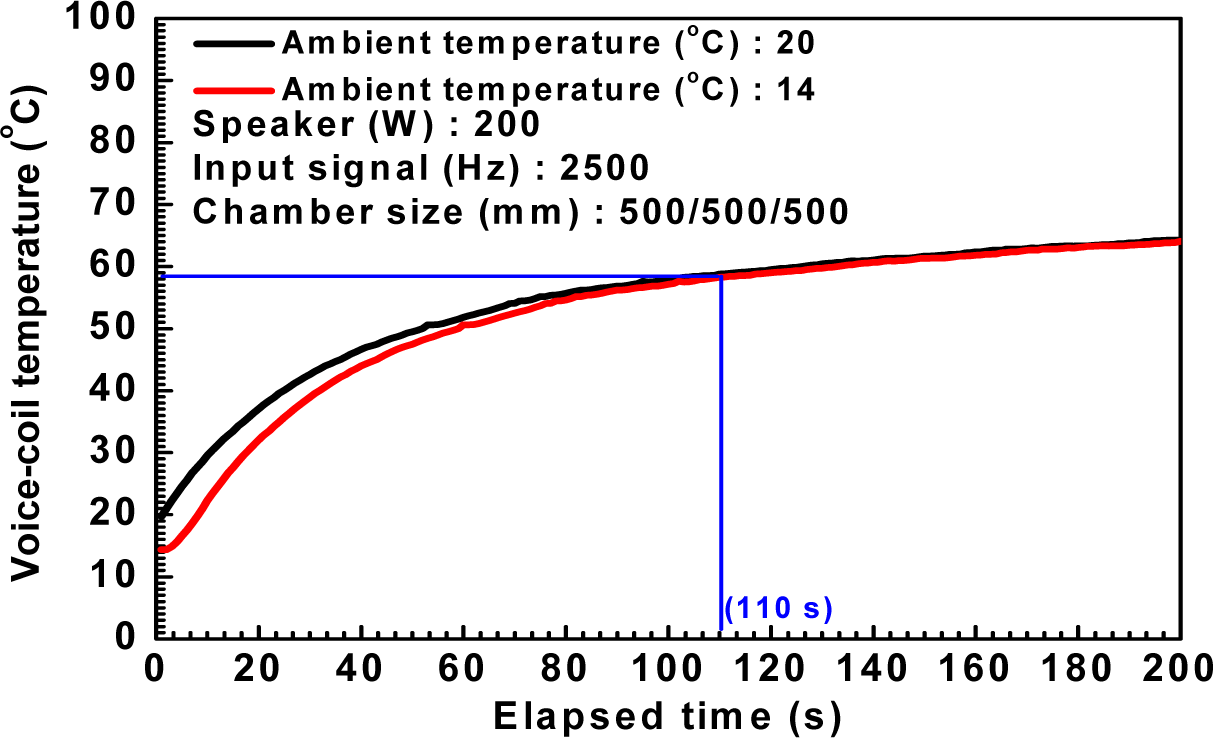
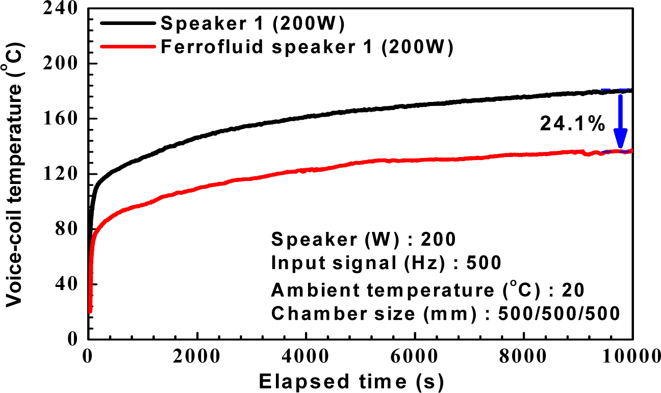
3.1. Temperatures Characteristics

Figure 5 shows the voice-coil and magnet temperatures of Speaker 1 with the variation of the input signals at an ambient temperature of 14 °C and a chamber size of 500 × 500 × 500 mm3. Temperatures of the voice-coil and magnet increased with the elapsed time during the test. Temperatures of the voice-coil and magnet at the input signal of 500 Hz and the elapsed time of 10,000 s were 108.6% and 80.1%, respectively, higher than those at 3000 Hz, as shown in Figure 5a,b. The temperature of the voice-coil decreased with the increase of the input signals from 500 Hz to 3000 Hz, due to more vibrating energy and less thermal energy loss. The increased vibrating energy by frequency means increased kinetic energy, and then, the thermal energy loss is comparatively decreased with the increase of the input signal, due to the reduced heat generated by the voice-coil. In addition, the voice-coil temperatures sharply increased until the elapsed time of 250 s, and the increasing rate of the voice-coil temperature gradually decreased with time due to the duration effect [1] (pp. 186–187). Generally, the heat generated by the voice-coil with the input signals increased the temperature of the voice-coil during a constant time at first, and after that, the heat of the voice-coil was dissipated to the outside. As shown in Figure 5c, at the elapsed time of 10,000 s, the heat transfer from the generated heat of the voice-coil to the magnet decreased with the increase of the input signals. The decreasing rate was calculated using the temperature differences between the voice-coil and the magnet by Equation (1).
Decreasing rate ( % ) = T v o i c e c o i l T p e r m a n e n t m a g n e t T v o i c e c o i l × 100
Figure 5. Temperature characteristics of Speaker 1 with the variation of the input signals.
Figure 6 shows the voice-coil temperature of Speakers 1 and 2 with the variation of the chamber sizes at an ambient temperature of 20 °C and an input signal of 2500 Hz. The effect on the chamber size of the voice-coil temperatures was shown clearly by decrease of the nominal power rating of the speakers. The voice-coil temperature of Speaker 2 (100 W) and Speaker 1 (200 W) at the elapsed time of 6000 s increased by 5.1% and 2.3%, respectively, with the decrease of the chamber size from 500 × 500 × 500 mm3 to 420 × 360 × 400 mm3. From the above results, the proper size selection of the enclosure is an important design factor to ensure the sound quality and effective heat transfer of the speaker. This is because the speaker efficiency, such as the sound quality, the harmonic distortion, the deflection and the mechanical damage, is affected by the heat generated by the voice-coil.
Figure 6. Temperature characteristics of Speakers 1 and 2 with the variation of the chamber sizes.
Figure 7 shows the voice-coil temperature of Speaker 1 and Speaker 2 with time at an ambient temperature of 20 °C, an input signal of 2500 Hz and a chamber size of 500 × 500 × 500 mm3. The voice-coil temperature of the speaker at the same input signal increased with the increase of the nominal power rating, because of the increased thermal compression with the increased current. The voice-coil temperature of Speaker 1 with a nominal power rating of 200 W at an elapsed time of 7000 s was 19.8% higher than that of Speaker 2 with a nominal power rating of 100 W.
Figure 7. Temperature characteristics of the speakers with the variation of the speaker power capacities.
Figure 8 shows the voice-coil temperatures of Speaker 1 with the variation of the ambient temperature at an input signal of 2500 Hz and a chamber size of 500 × 500 × 500 mm3. The voice-coil temperature of Speaker 1 under both ambient temperatures is met approximately after the elapsed time of 110 s. Accordingly, the ambient temperature is not affected by the heat transfer characteristics, because the heat generated by the voice-coil with the input signal of 2500 Hz was much larger than the temperature difference between ambient temperatures.
Figure 8. Temperature characteristics of Speaker 1 with the variation of the ambient temperatures.

3.2. Ferrofluid Effects

Figure 9 shows the voice-coil temperature of Speaker 1 with time at an ambient temperature of 20 °C, an input signal of 500 Hz and a chamber size of 500 × 500 × 500 mm3. Due to the burn out problem of the voice-coil, as well as the sound quality, decreasing the voice-coil temperature of the speaker is a key design parameter to decide the performance of the speaker. The voice-coil temperature of Speaker 1 using the ferrofluid in the amount of 650 μL at an elapsed time of 10,000 s was 24.5% lower than that of the general Speaker 1, because of the enhanced efficiency of Speaker 1 using the ferrofluid [1] (pp. 190–192). In addition, the heat transfer characteristics, including the isotherms and the Nusselt numbers of the ferrofluid, were generally enhanced by the superficial magnetic volume force with the magnetic force (magnet), as mentioned in Lee et al. [10].
Figure 9. Temperature characteristics of the voice-coil between Speaker 1 and Speaker 1 with ferrofluid.

4. Conclusions

This paper investigated the temperature and heat transfer characteristics of speakers with variations of the speaker power ratings, ambient temperatures, chamber sizes and input signals and also considered the effects of ferrofluid on the temperatures of the voice-coil and magnet of the speaker. Especially the speaker using the ferrofluid was designed to decrease the temperature of the voice-coil for the purpose of increasing the sound quality and avoiding the burn out problem. Temperatures of the voice-coil and magnet increased with time due to the thermal linearity. Temperatures of the voice-coil and magnet at the input signal of 500 Hz and the elapsed time of 10,000 s were shown to be 108.6% and 80.1% higher, respectively, than those at 3000 Hz. The voice-coil temperatures significantly increased at first, and the increasing rate of the voice-coil temperature gradually decreased with time due to the duration effect. The effect on the ambient temperature of the voice-coil temperature was relatively low, because the heat generated by the voice-coil was much larger than the temperature difference between ambient temperatures. Under an ambient temperature of 20 °C and an input signal of 2500 Hz, the voice-coil temperature of Speaker 1 at an elapsed time of 5000 s increased by 5.5% with a 48.4% decrease of the chamber size from 500 × 500 × 500 mm3 to 420 × 360 × 400 mm3. The voice-coil temperature of the speaker at the same input signal increased with the increase of the nominal power rating, because of the increased thermal compression with the increased current. The voice-coil temperature of the speaker 1 (200 W) using the ferrofluid of an amount of 650 μL at an elapsed time of 10,000 s was 24.5% lower than that of general Speaker 1, because of the enhanced efficiency of Speaker 1 using the ferrofluid.

Acknowledgments

This work was supported by the Dong-A University research fund.

Author Contributions

Moo-Yeon Lee is the first and the corresponding author. He designed the research and wrote the paper. All results and discussions are performed by Moo-Yeon Lee. Hyung-Jin Kim is a co-author. He performed the tests and drew figures in the paper. Both authors have read and approved the final manuscript.

Conflicts of Interest

The authors declare no conflict of interest.

References

  1. Oh, S.J. Fundamentals of Loudspeaker Engineering; Seok HakDang: Seoul, Korea, 2006. [Google Scholar]
  2. Lee, H.S.; Yoo, J.G. Befitting test of magnetic fluid to speaker damper. J. Korean Magn. Soc 1998, 8, 93–98. [Google Scholar]
  3. Klippe, W. Nonlinear modelling of the heat transfer in loudspeakers. J. Audio Eng. Soc 2004, 52, 3–25. [Google Scholar]
  4. Hsu, T.S.; Poornima, K.A. Loudspeaker failure modes and error correction techniques. Appl. Acoust 2001, 62, 717–734. [Google Scholar]
  5. Pan, N.; Shen, C.; Wang, S.F. Experimental study on forced thermoacoustic oscillation driven by loudspeaker. Energy Convers. Manag 2013, 65, 84–91. [Google Scholar]
  6. Koh, S.J.; Lee, K.J.; Kang, J.H.; Oh, G.H.; Sung, K.H.; Kim, C.J. Development of a temperature prediction tool for voice-coils in loudspeakers using CFD analysis. Proceedings of the Korean Society of Mechanical Engineers, Hang-Won, Korea, 23 April 2008; pp. 41–44.
  7. Kim, H.J.; Seo, J.H.; Lee, W.Y.; Yeom, J.K.; Lee, M.Y. Numerical simulation on heat transfer performance of the woofer speaker with the variation of voice-coil and bobbin structures. Proceedings of 2013 Winter the Society of Air-Conditioning and Refrigarating Engineers of Korea, Seoul, Korea, 22 November 2013; pp. 41–42.
  8. Lee, M.Y.; Kim, H.J.; Lee, W.Y. Numerical analysis on temperature characteristics of the voice-coil for woofer speaker using ferrofluid. J. Korean Magn. Soc 2013, 23, 166–172. [Google Scholar]
  9. Lee, H.S.; Yoo, J.G. Befitting test of magnetic fluid to speaker damper. J. Korean Magn. Soc 1998, 8, 93–98. [Google Scholar]
  10. Lee, M.Y.; Seo, J.H. Numerical investigation on heat and flow characteristics of temperature-sensitive ferrofluid in a square cavity. Adv. Mech. Eng 2013. [Google Scholar] [CrossRef]

Article Metrics

Citations

Article Access Statistics

Multiple requests from the same IP address are counted as one view.