3.1. Conventional Diabatic CAES System (with Fuel)
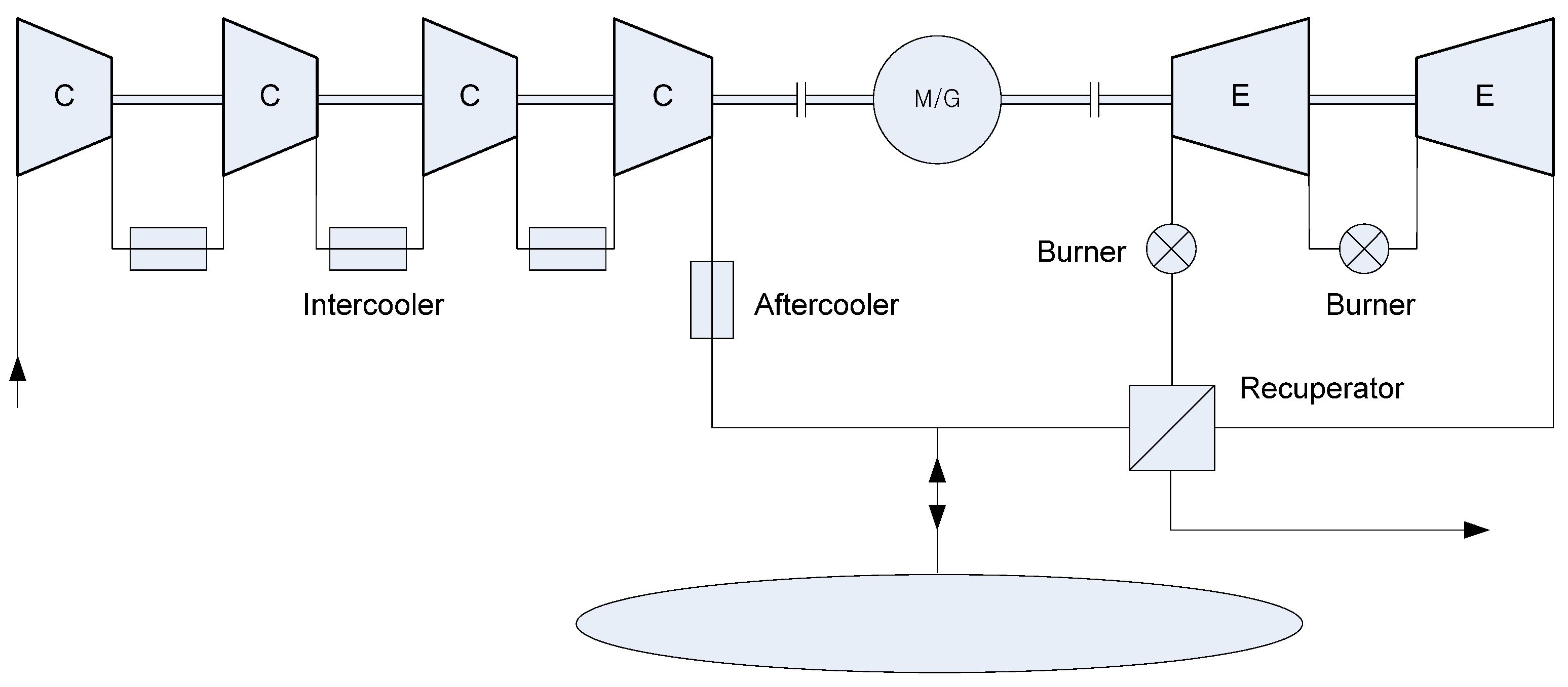
In the case of conventional CAES plants such as the one shown in
Figure 1, in order to increase the overall efficiency of the system, it is customary to perform multistage compression with intercooling and multistage expansion with reheating, and for the discharging process, the compressed air is generally heated using gas fuel.
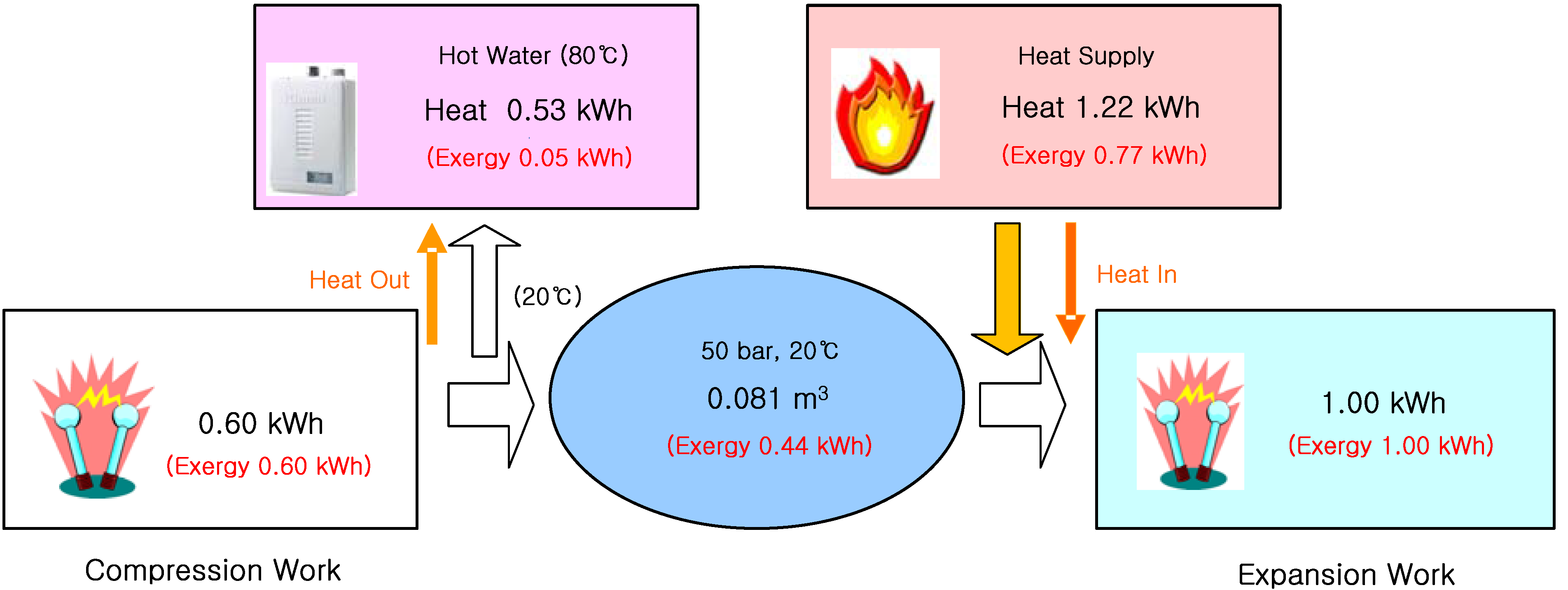
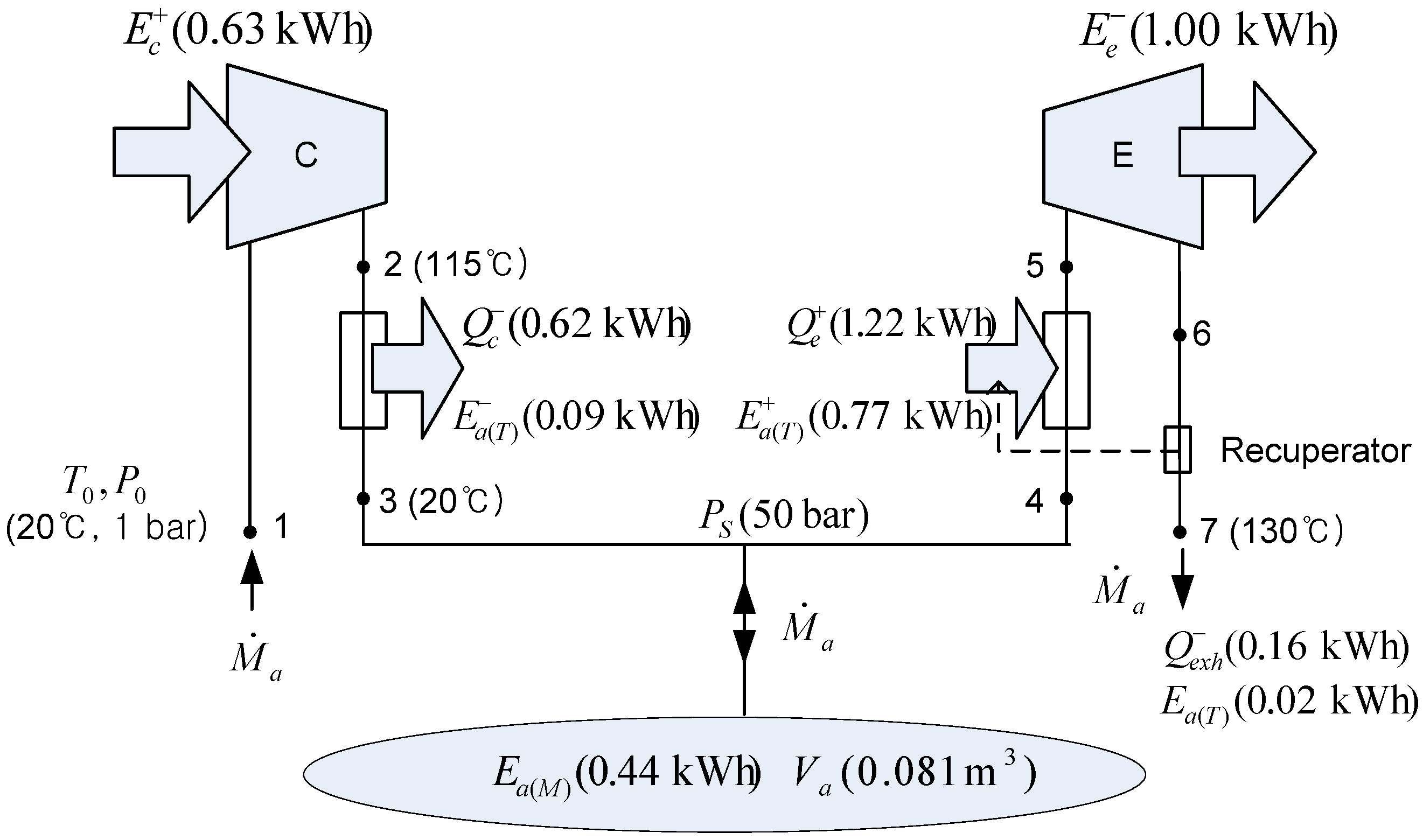
Figure 3 shows the energy and exergy flow of the diabatic CAES system for the production of 1-kWh output.
Figure 3.
Energy and exergy flow of the conventional CAES system.
Figure 3.
Energy and exergy flow of the conventional CAES system.
The CAES system in
Figure 3 is based on the McIntosh plant, which has four-stage compression with intercooling and an exhaust gas temperature of 130 °C. The heat input is 1.22 kWh to produce 1 kWh electric output, and the inlet temperatures of high pressure (HP) turbine with the inlet pressure of 50 bar and low pressure (LP) turbine with the inlet pressure of 15 bar are 537 °C and 871 °C, respectively. The electric power is 2.26 times higher than the exergy of the compressed air by the thermal exergy added by using fuel. The thermal exergy of 0.77 kWh in
Figure 3 is not chemical exergy but a total thermal exergy added in form of heat during the multistage expansion with reheating. In general, the energy efficiency of the CAES system can be calculated by adding the heat input by natural gas,
Q, to the electric input as follows [
13,
16,
17]:
But, this value may not be considered a useful measure of electrical storage efficiency, because the heat input is not equivalent to the electric input. Rather, it may be seen as a mixed efficiency of the electrical storage efficiency and thermal efficiency of a power plant.
Therefore, the net electrical storage efficiency of a CAES system can be calculated by adding the amount of electric energy generated by natural gas (or other fuels) to the electric input of the CAES system as follows [
13,
16,
17]:
where
Qηp is the electric energy that would be produced if the amount of fuel consumed by the CAES system were burned in another power station (
Q is the lower caloric value of the fuel and
ηp is the efficiency of the conventional power plant).
If the standard thermal efficiency of the power plant
ηp = 0.4 [
18] is assumed, the net electrical storage efficiency of the CAES system shown in
Figure 3 is 89%. However, if the thermal efficiency of a conventional power plant,
ηp = 0.5, is used as the standard, the net electrical storage efficiency of the CAES system is 81%. Therefore, the net electrical efficiency of the CAES system, defined in Equation (12), depends significantly on the value of
ηp used. Further, when the heat is obtained from waste heat or solar power, the net electrical storage efficiency of a CAES system becomes more ambiguous.
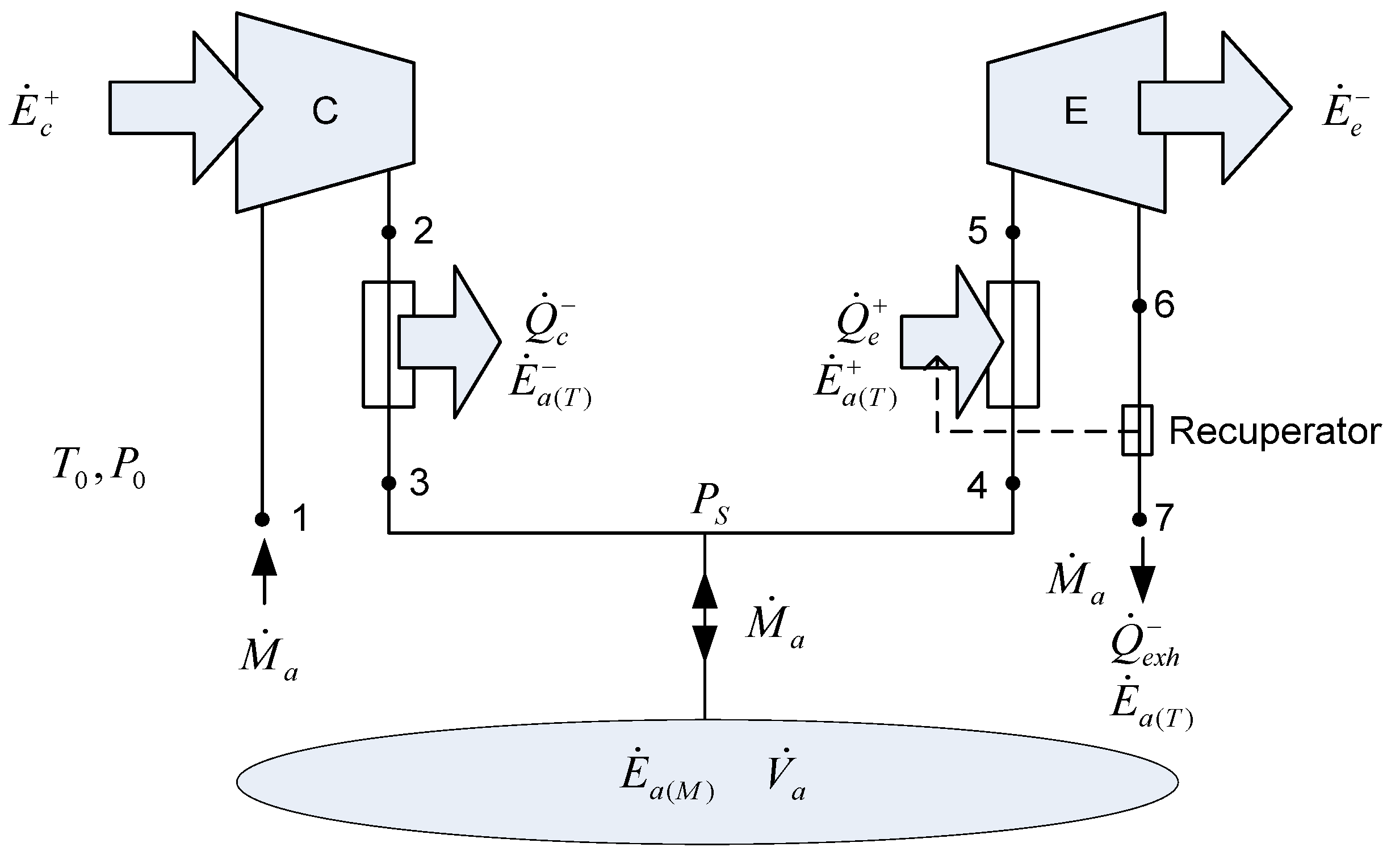
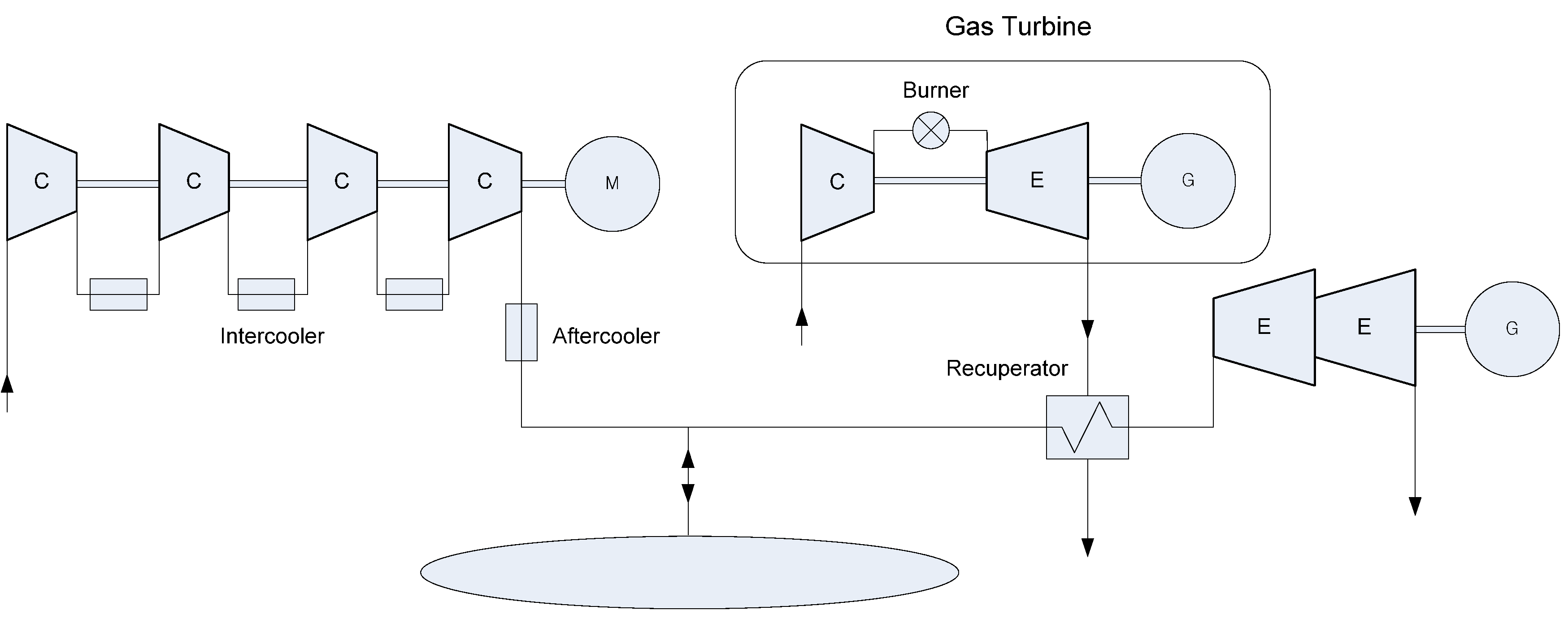
Figure 4 shows a new configuration of diabatic CAES configuration, one that uses a conventional gas turbine and the exhaust heat from the gas turbine to heat the compressed air before it reaches the expander, as a CAES bottoming cycle [
19].
Figure 4.
Configuration of CAES system as a bottoming cycle.
Figure 4.
Configuration of CAES system as a bottoming cycle.
Therefore, in this paper, a new expression for the electrical storage efficiency of the CAES system, based on the exergy analysis, has been proposed. It is given as:
where
Ea(T) is the thermal exergy of compressed air added by heat sources.
The new electrical storage efficiency of the CAES system in
Figure 3 is 71%. Unlike the conventional gas turbine system, in the case of the CAES system, there is a very little exergy loss of exhaust gas. This advantage can compensate for the exergy loss of heat of compression. Although the heat of compression is dissipated in existing CAES plants, it is possible for this dissipated heat to be used for residential heating through cogeneration, which can contribute to improved energy efficiency. Moreover, although existing CAES plants use fossil fuel, waste heat and several other types of renewable energies such as solar, biomass, and biogas can be used as heat sources in the CAES system. SolarCAT Inc. has developed an energy storage technology using compressed air energy storage and concentrating solar power (CSP) design concepts. The company’s design replaces the CAES facility’s expander train with multiple expanders integrated with parabolic dish solar collectors, which reflect and concentrate incident sunlight onto their focal receivers to heat the compressed air fed to the collectors from storage [
4].
3.2. Adiabatic CAES System
One of the drawbacks of existing CAES systems is the use of fuel. Adiabatic CAES uses no fuel to heat the compressed air for the expansion process, representing an emission-free, pure storage technology with high storage efficiency [
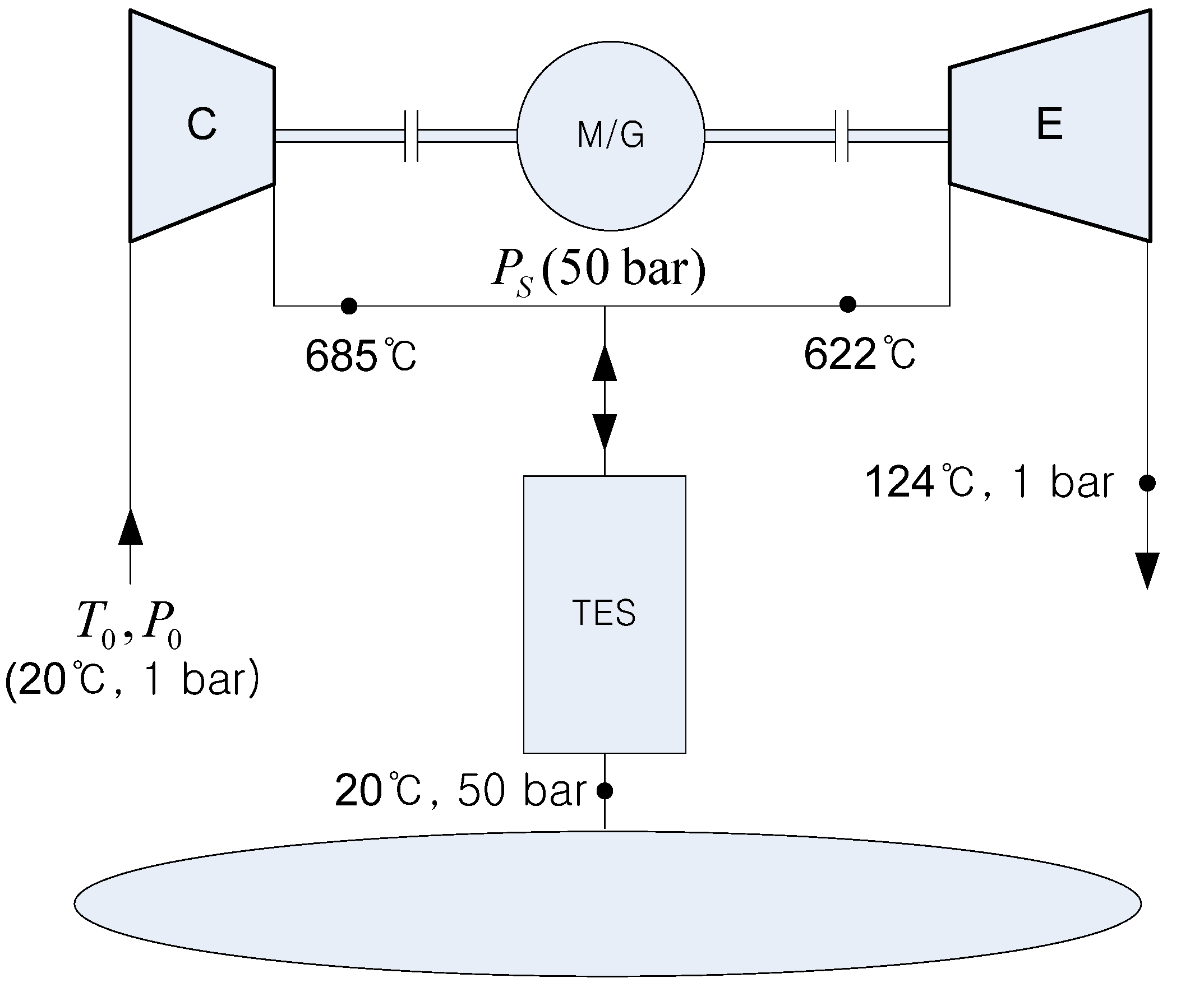
4]. The basic idea of the adiabatic CAES concept is the use of heat storage as the central element of the plant, as shown in
Figure 5 [
4,
20,
21]. This implies that the heat needed to heat the compressed air for the expansion process is recovered from the compression and stored in a thermal energy storage (TES) unit to eliminate the need for a combustor [
13].
Figure 5.
Diagram of an adiabatic CAES system in single-stage configuration.
Figure 5.
Diagram of an adiabatic CAES system in single-stage configuration.
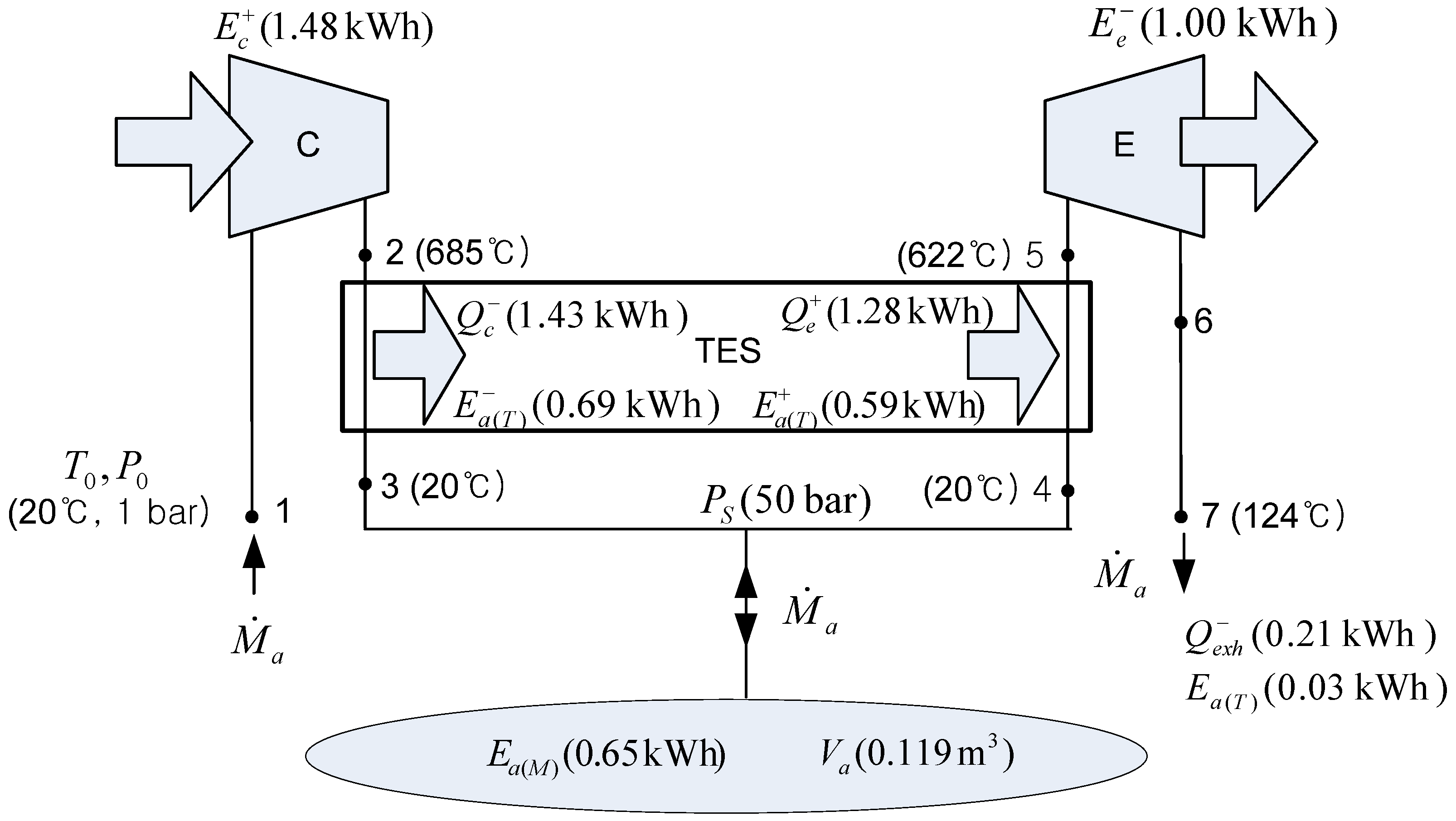
Figure 6 shows the energy and exergy flow of the adiabatic CAES system in single-stage configuration for the production of 1 kWh output.
If the air is compressed up to 50 bar adiabatically, the outlet air temperature of compressor is about 685 °C. The thermal exergy of the compressed air is roughly equivalent to the mechanical exergy of the compressed air . During the charging process, the heat is extracted from the compressed air and stored. When the grid demands electric power, the compressed air is heated using the thermal energy storage up to 622 °C and expanded through an air turbine. It was assumed that the efficiency of TES (the ratio of heat input to the compressed air to the heat output from the compressed air) is 90%. Then, the electrical storage efficiency of the adiabatic CAES system without any external thermal input is 68%. The adiabatic CAES can be considered a combination of CAES and TES, because a substantial portion of the exergy is stored in the form of thermal energy.
Figure 6.
Energy and exergy flow of the adiabatic CAES system in single-stage configuration.
Figure 6.
Energy and exergy flow of the adiabatic CAES system in single-stage configuration.
Adiabatic CAES technology was evaluated previously in the European research project. The resulting conceptual designs of the four main plant components (compressor, heat storage, cavern, and air turbine) helped to identify some key technical risks as well as a substantial need for further development efforts, particularly for the adiabatic compression and the heat storage device. The outlet temperature of the compressor is maintained above 600 °C, and the corresponding compression heat is stored in the TES consisting of an arrangement of solid materials, typically ceramic bricks or natural stones [
4,
21].
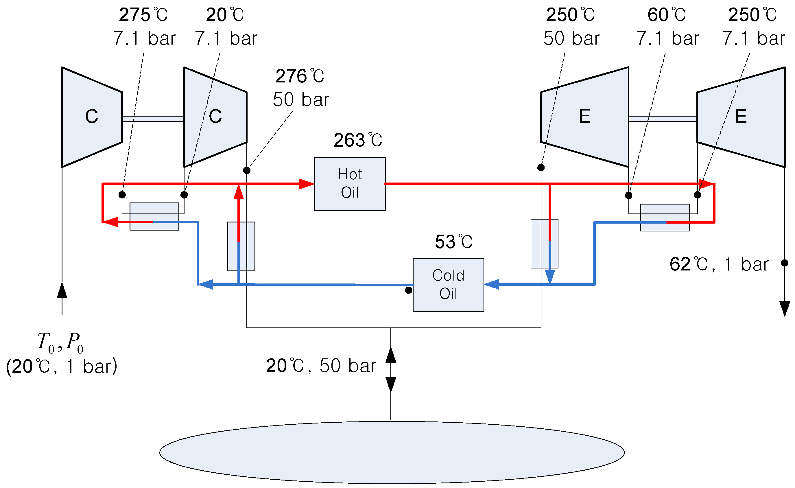
Another configuration of adiabatic CAES is shown in
Figure 7, using cold and hot oil as the TES [
7,
8]. During charging process, the oil is flowing from a cold tank to a hot tank to intercool the compressed air. Inversely, during discharging process, the oil is flowing from the hot tank to the cold tank to heat the compressed air for power production. The design is based on using standard, industry-proven equipment components.
Figure 7.
Diagram of an adiabatic CAES system in two-stage configuration.
Figure 7.
Diagram of an adiabatic CAES system in two-stage configuration.
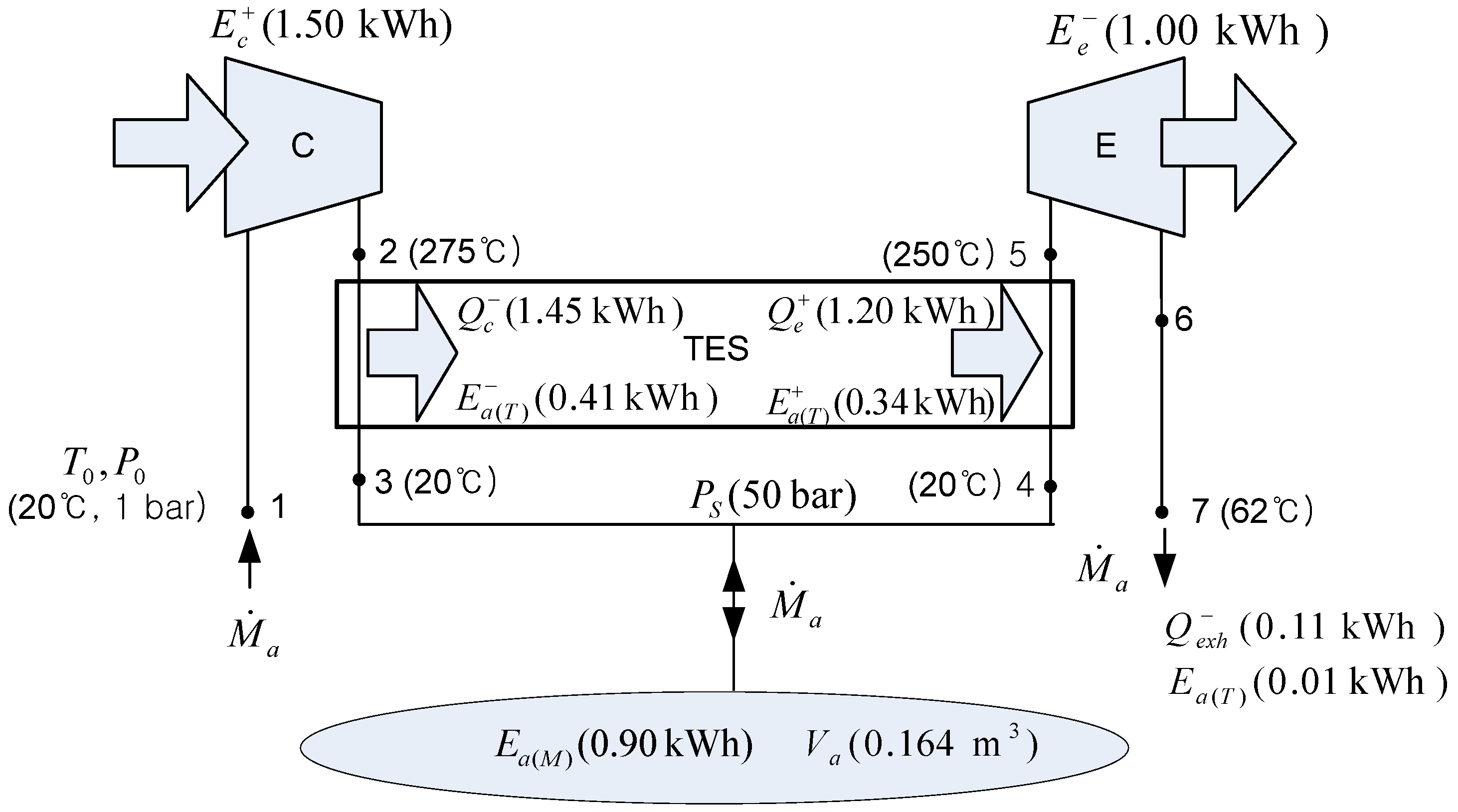
Figure 8 shows the energy and exergy flow of the adiabatic CAES system in two-stage configuration for the production of 1 kWh output.
Figure 8.
Energy and exergy flow of the adiabatic CAES system in two-stage configuration.
Figure 8.
Energy and exergy flow of the adiabatic CAES system in two-stage configuration.
If the air is compressed up to 50 bar in two stages, the outlet air temperature of compressor is about 275 °C. The thermal exergy of the compressed air, , is less than half of the mechanical exergy of the compressed air, . During the charge period, the heat is extracted from the compressed air and stored by the flowing oil. When the grid demands electric power, the compressed air is heated using thermal energy storage up to 250 °C and expanded through an air turbine. The efficiency of TES is assumed to be 90%, as in the previous adiabatic CAES system in single-stage configuration. Then, the electrical storage efficiency of the adiabatic CAES system without any external thermal input is 67%. This adiabatic CAES configuration needs greater air storage than does the prior one, because its TES exergy storage is much smaller than the prior one, due to the lower temperature of TES.
3.3. Isothermal CAES System
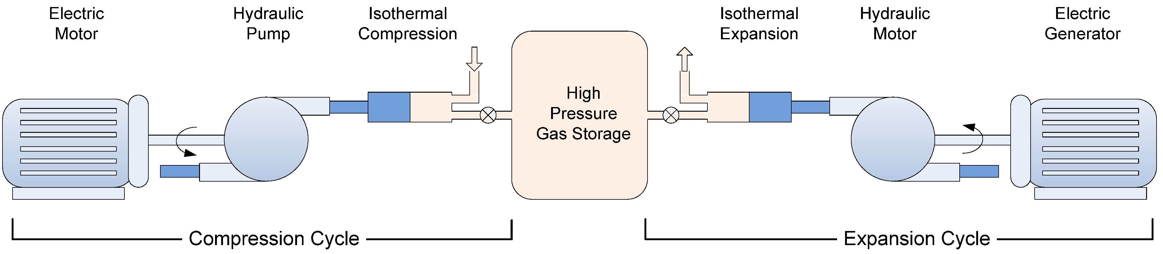
Isothermal CAES is an alternative CAES system which eliminates the need for fuel and high temperature thermal energy storage. Isothermal CAES can minimize the compression work and maximize the expansion work done through isothermal compression/expansion by means of effective heat transfer with the vessel’s surroundings, which involves slow gas pressure change by liquid piston [
4,
9]. The CAES systems of SustainX Inc. and Enairys Powertech Ltd. use hydraulic pumps to isothermally compress air at rates that allow the high-pressure air to exchange heat with its surroundings, as shown in
Figure 9. During isothermal expansion, the gas is able to do more work by absorbing heat from its surroundings. The expanding air in the isothermal CAES system drives a hydraulic motor, which in turn drives an electric generator. The use of hydraulic pumps and motors enables precise compression and expansion of air, heat transfer with the surroundings, and a high level of thermal and overall system efficiency [
4,
9].
Figure 9.
Function diagram of an isothermal CAES system (Source: SustainX Inc., Seabrook, NH, USA).
Figure 9.
Function diagram of an isothermal CAES system (Source: SustainX Inc., Seabrook, NH, USA).
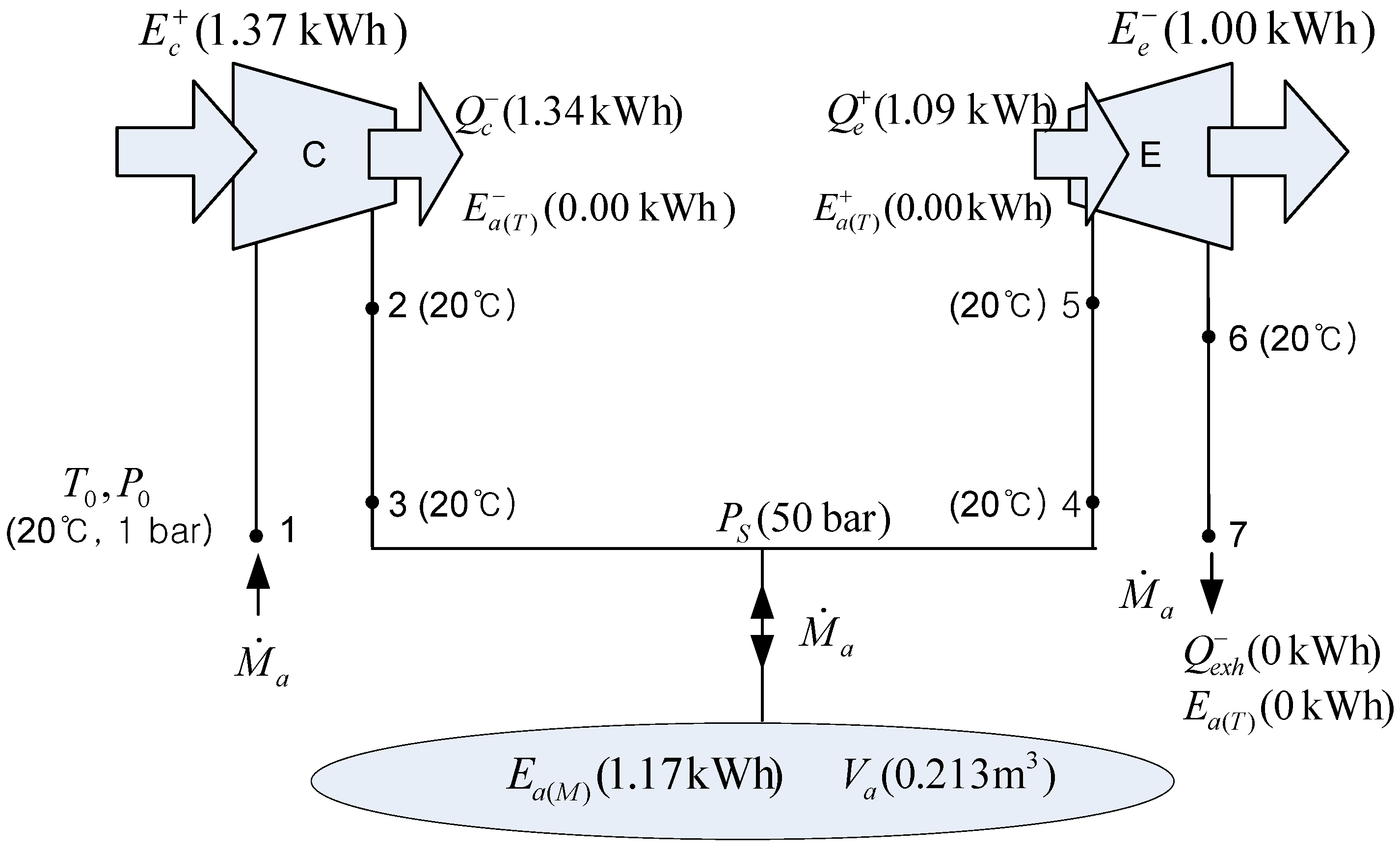
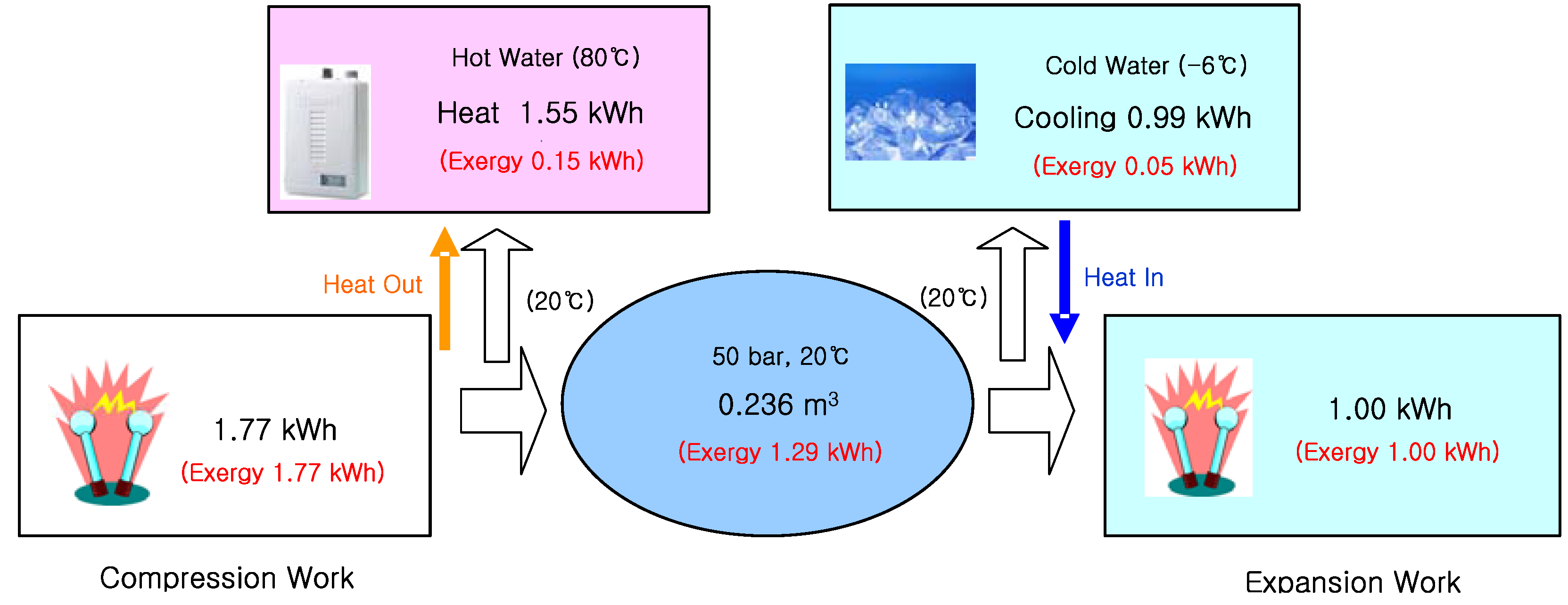
Figure 10 shows the energy and exergy flow of the isothermal CAES system for the production of 1 kWh output. The air is compressed up to 50 bar isothermally and stored; then, the compressed air is expanded isothermally. The ideal isothermal compression and expansion work,
and
, respectively, can be obtained as follows:
where the working fluid is assumed to be real gas then Δ
h is very small but not equal to zero.
Figure 10.
Energy and exergy flow of the isothermal CAES system.
Figure 10.
Energy and exergy flow of the isothermal CAES system.
The isothermal efficiencies of compression and expansion,
ηc,t and
ηe,t, respectively, are expressed as:
where
and
are the actual compression work and expansion work considering a loss of mechanical work by internal dissipation and a small temperature deviations from isothermal process.
It was assumed that the isothermal efficiencies of compression and expansion were 90%, considering the high efficiency of the hydraulic pump/motor and the effective heat transfer with its surroundings; the isentropic effciencies of hydraulic water pump/motor are 92%~94% [
9] and it was repoted that the temperature deviation during the expansion (or compression) process from 1 bar to 200 bar is less than 12 °C by water injection, which means that the work by integrating the pressure-volume curve is 96% of isothermal work (source: SustainX Inc.).
Although there is much heat transfer between the system and its surroundings for the compression and expansion processes, the thermal exergy of the air is nearly equal to zero, because the temperature change of the air is very small. Although the isothermal CAES system requires about twice the volume of air storage in comparison with the conventional (diabatic) and adiabatic CAES systems, because no thermal exergy is added to the compressed air for the discharging process, the use of high pressure (from 1 bar to 200 bar) reduces the storage volume required. The electrical storage efficiency of the isothermal CAES system without external thermal input is 73%.
3.4. Trigeneration Micro-CAES System
Large-scale CAES is very dependent on appropriate geological formations for air storage. Micro-CAES with subsurface or aboveground pressure vessels is a more adaptable solution, especially for distributed generation [
22,
23,
24]. Also compressed air is a commonly used utility across most manufacturing and processing industries as its production and handling are safe and easy [
25]. Micro-CAES systems can be used as a multipurpose system, as a combination of energy storage and air cycle heating and cooling. In general, air cycle refrigeration consists of one or more compressors (fan), turbines (expanders), and heat exchangers; the setup is very similar to the CAES system except for the air storage vessels. Air cycle heating and cooling has many advantages, including high reliability, ease of maintenance, flexibility of temperature, and heating and cooling capacities. In addition, it employs a natural refrigerant, which is environmentally benign [
26,
27,
28,
29]. The air cycle approach is one of the most promising long-term alternatives for refrigeration machines, air conditioners, and heat pumps [
26]. Air cycle is widely used in industrial freezing with a very low temperature (below −50 °C) and transport refrigeration. In the case of conventional refrigeration and air conditioning, the air cycle approach suffers from low energy efficiency and so is not competitive with vapor compression cycles [
27]. But, air cycles have been studied for HVAC in office buildings within the framework of European research projects, since they have advantages in applications that require both heating and cooling [
26,
29] and because of the potential of highly efficient turbo machinery that is used [
27,
28].
The micro-CAES system combined with air cycle heating and cooling could be a very good solution because it would then be possible to improve the energy efficiency and economics of the system as a multipurpose system. Transportable CAES was proposed as a solution to provide power and energy for desalination of brackish water or seawater for an island by utilizing the superchilled air as a by-product for the freeze-crystallizing process [
30]. A new CAES refrigeration system was proposed for electrical power load shifting—one that employs a combination of an air cycle refrigeration cycle and a vapor compression cycle, in which the cooling effect of expanding air is used and the expansion power is used to drive a compressor of the vapor compression cycle [
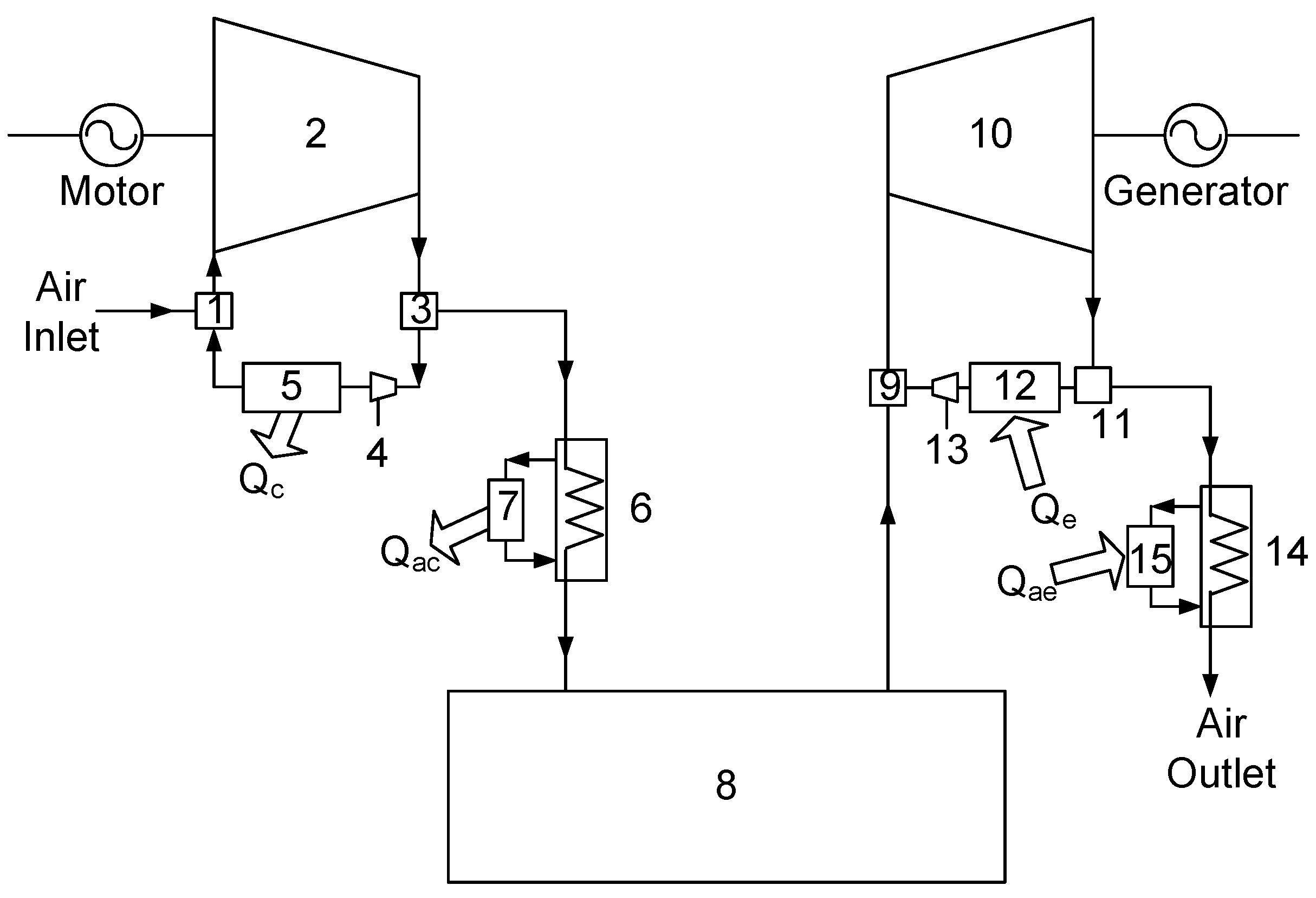
31]. This paper focuses on a micro-CAES system for energy storage and air cycle heating and cooling for HVAC of a building. Because the pressure ratio of CAES is much higher than that of conventional air cycle refrigeration to reduce the volume of air storage, multiple-stage compression and expansion is needed to achieve high efficiency for the system; this is effected by matching the temperature of compressed and expanded air to the required temperature of heating and cooling load. Otherwise, quasi-isothermal compression and expansion by liquid injection can be used for a high efficiency micro-CAES and air cycle heating and cooling system [
10]. To achieve quasi-isothermal compression and expansion, a large amount of atomized water is injected during both processes, as shown
Figure 11.
Figure 11.
Trigeneration micro-CAES system: (1) mixer, (2) compressor, (3) separator, (4) hydraulic motor, (5), (6), and (7) heat exchanger, (8) high pressure vessel, (9) mixer, (10) expander, (11) separator, (13) pump, and (12), (14), and (15) heat exchanger [
10].
Figure 11.
Trigeneration micro-CAES system: (1) mixer, (2) compressor, (3) separator, (4) hydraulic motor, (5), (6), and (7) heat exchanger, (8) high pressure vessel, (9) mixer, (10) expander, (11) separator, (13) pump, and (12), (14), and (15) heat exchanger [
10].
The concept is the same as that of a liquid-flooded compressor and expander in an Ericsson cycle cooler proposed by Hugenroth
et al. [
32]. Water (or liquid) is discharged together with compressed air; then it is separated, cooled, and recirculated. Compressed air is cooled to the ambient temperature by water circulation through a cooler, and it is then stored in vessels. Hot water separated after the compression and hot water from the cooler can be used to satisfy the heating load. To achieve quasi-isothermal expansion, as in the compression process, liquid can be injected into the expander, separated, used to supply the cooling load, and pressurized by a pump for injection. In the course of the analyses, additional compression work owing to liquid during the compression process or pumping work for liquid injection during the expansion process was neglected, because either kind of work supplies only a small percent (2%–3%) of the work of gas, and the additional work input owing to liquid can be recovered by hydraulic motor during the compression process or by expander during the expansion process.
The quasi-isothermal compression or expansion process can be modeled as a polytropic process (
Pvn = const). The temperature change of gas during the polytropic process can be obtained as follows:
In the case of quasi-isothermal compression or expansion, it is possible to match the temperature after compression to the heating temperature required or the temperature after expansion to the cooling temperature required by controlling the mass flow rate of injected liquid, i.e., by changing the polytropic index n.
The ideal compression and expansion work can be obtained as follows:
Actual compression and expansion work can be obtained using an isentropic efficiency defined, respectively, as:
Heat transfer from the gas to the liquid during the compression process and from the liquid to the gas during the expansion process can be obtained as follows:
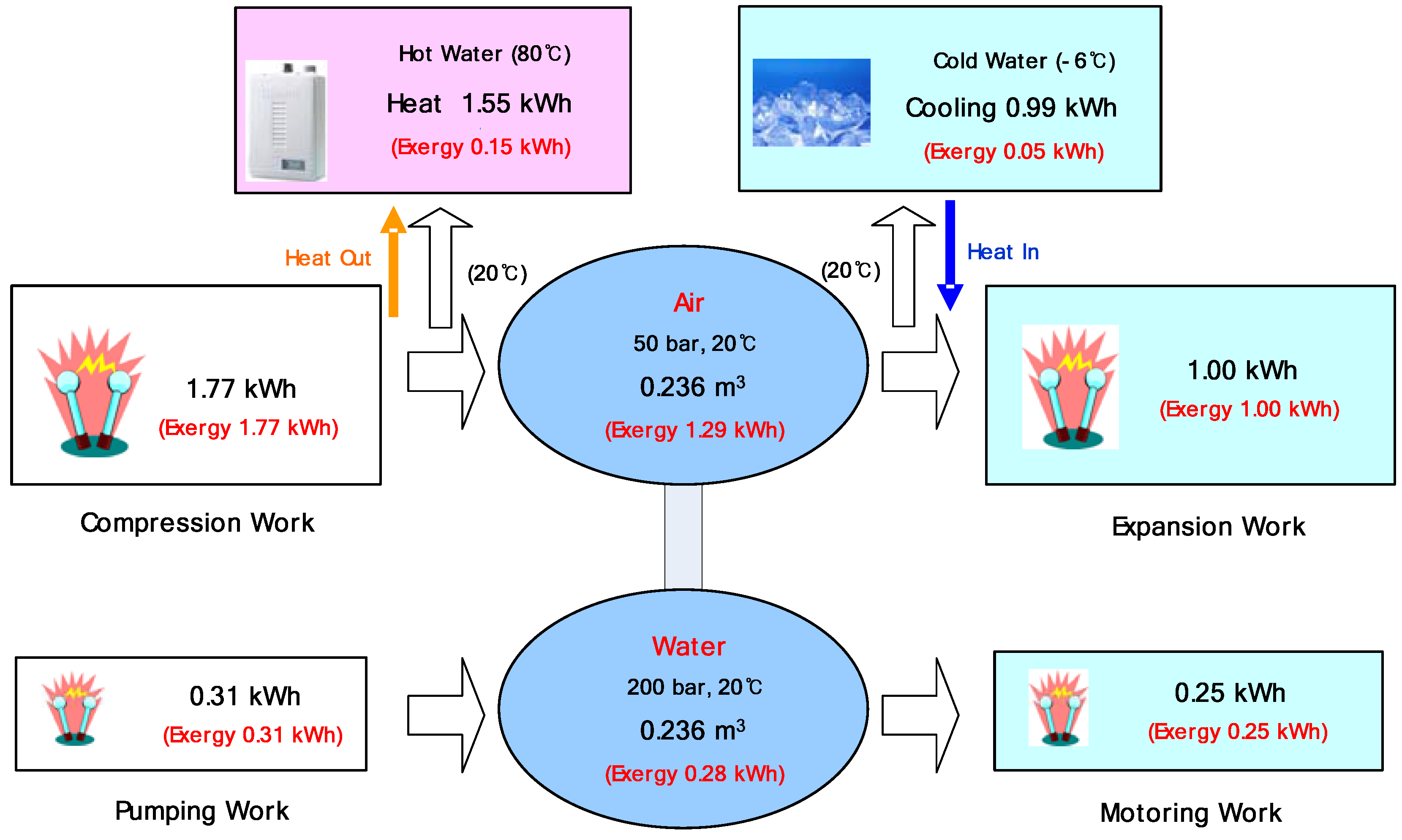
Figure 12 shows the energy and exergy flow of the trigeneration micro-CAES system for the production of 1 kWh output. The case of one stage of quasi-isothermal compression with (
n = 1.05) and expansion (
n = 1.025) with liquid injection was considered. It was assumed that the isentropic efficiencies of the compressor and expander are 85%, the efficiencies of the motor and generator are 95%, and we can use 90% of the heat of compression and cooling effect of expanding air. The electrical storage efficiency of the micro-CAES system without any external thermal input is 57%. In addition, hot and cold water accompanied by a significant amount of heat transfer are available, in which the COP of the heat pump (COP
HP =
Qhot/
Enet) is equivalent to 2.0 and the COP of refrigeration (COP
R =
Qcold/
Enet) is equivalent to 1.3. Considering the thermal exergy of the hot and cold water, the second law efficiency of the trigeneration micro-CAES system (
ηII) is 68%.
Figure 12.
Energy and exergy flow of trigeneration micro-CAES system.
Figure 12.
Energy and exergy flow of trigeneration micro-CAES system.
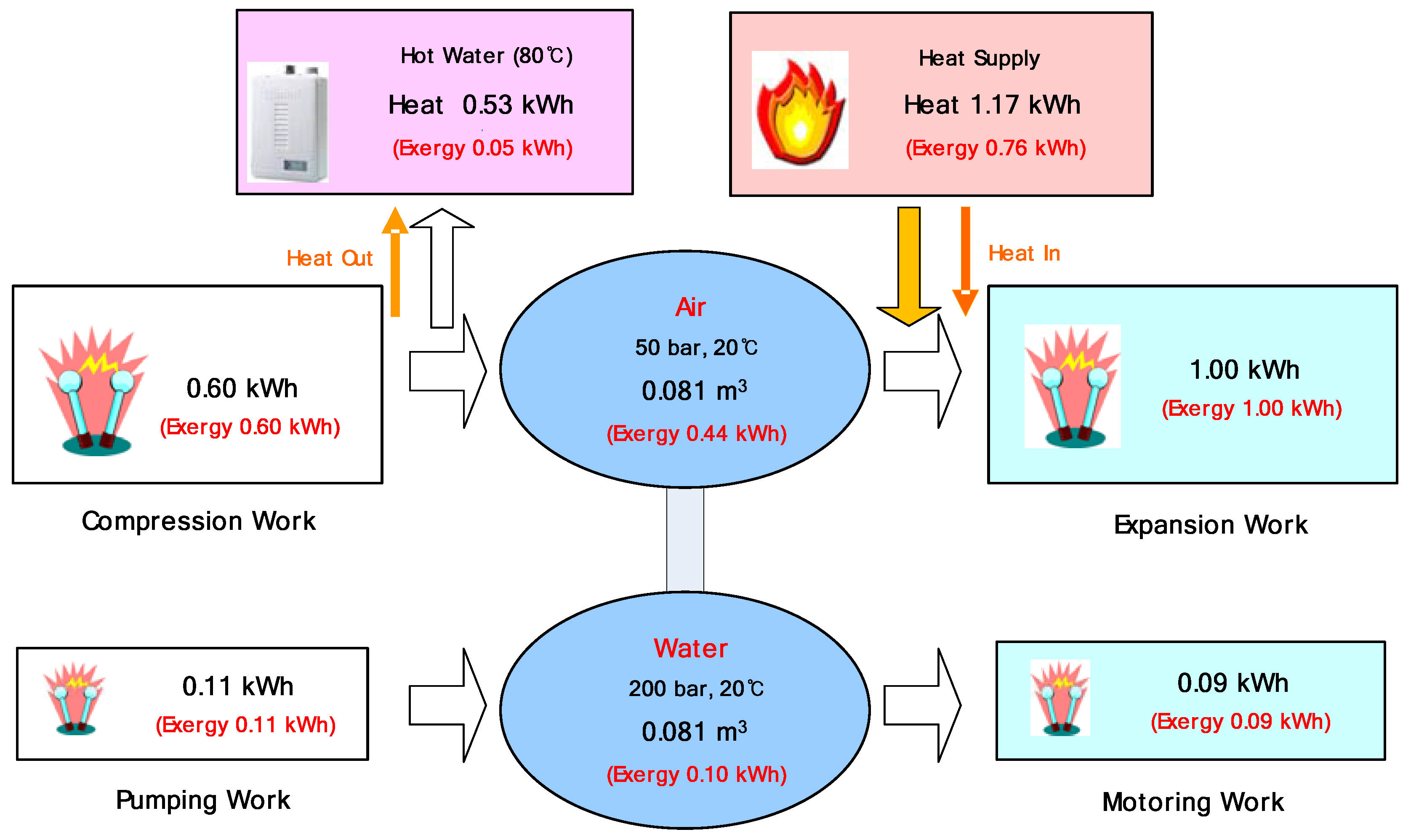
To obtain increased electric power without use of the cooling effect, a heater (or combustor) can be used to heat the compressed air.
Figure 13 shows the energy and exergy flow of the micro-CAES system with fuel, as in the conventional CAES system.
Figure 13.
Energy and exergy flow of micro-CAES system with the fuel.
Figure 13.
Energy and exergy flow of micro-CAES system with the fuel.
3.5. Constant-Pressure CAES System Combined with Pumped Hydro Storage
Conventional CAES systems are most commonly operated under constant volume conditions with a fixed, rigid reservoir operating over an appropriate pressure range [
15,
20]. These varying pressure ratios can degrade the efficiencies of compression and expansion due to deviation from design points. Existing CAES plants were designed to throttle the cavern air to a designed pressure despite the throttling loss. The exergy loss of compressed air by throttling is about 5%–8% in existing CAES systems [
11]. Although it is possible to increase the storage volume to reduce the operating pressure range, doing so results in low energy density and high construction costs. Therefore, in order to resolve such problems, a new constant-pressure CAES system combined with pumped hydro storage was proposed [
11,
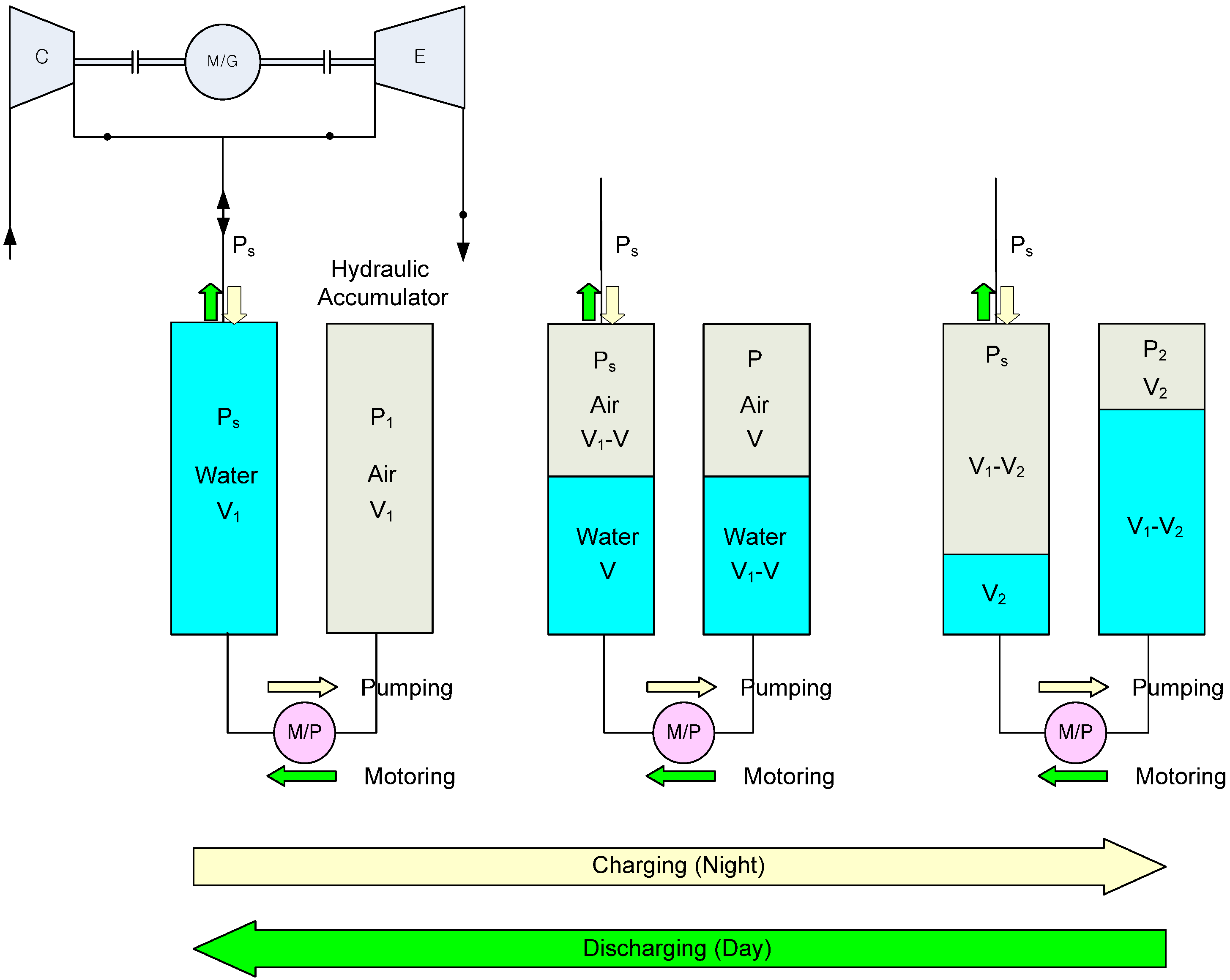
12]. The system combines constant-pressure air storage and hydraulic energy storage, as shown in
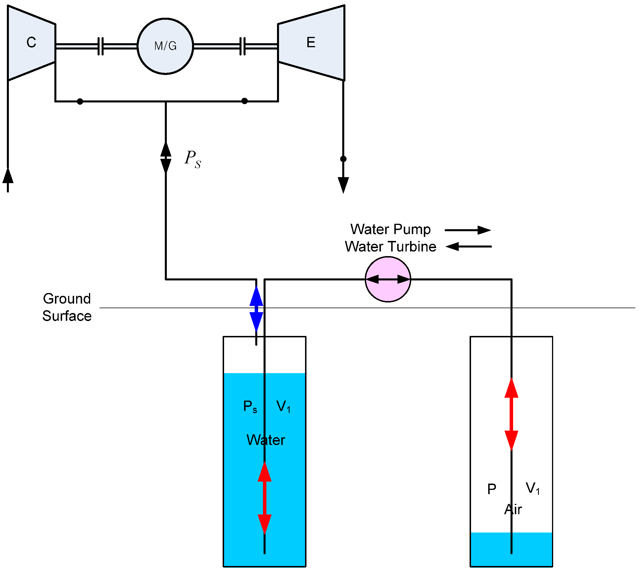
Figure 14. During the charging process, the water in an air storage vessel (left) is transferred to a hydraulic accumulator (right) by a pump to maintain a constant pressure of air storage, consuming power. During the discharging process, the water in the hydraulic accumulator is returned to the air storage vessel through a water turbine to maintain a constant pressure of air storage, producing power.
The compression/expansion process of the enclosed air in the right tank is assumed to be a isothermal process (
PV = const) that results from sufficient heat transfer with the environment considering that the pressure ratio of the sealed air, P
2/P
1, is low and the compression/expansion process is a very slow process over the charging/discharging process. The exergy of compressed air part (
Ea) and hydraulic part (
Eh) can be expressed, respectively, as [
11]:
where
V1 and
V2 are the volumes of air in the hydraulic accumulator at the start and end of the charging process, respectively;
P1 is the pressure of air in the hydraulic accumulator at the start of charging process; and
P0 and
PS are ambient pressure and constant pressure of air storage, respectively.
Figure 14.
Constant-pressure CAES system combined with pumped hydro storage (PHS) [
11].
Figure 14.
Constant-pressure CAES system combined with pumped hydro storage (PHS) [
11].
This concept can be applied to both small-scale CAES using manmade air vessels and large-scale CAES using salt caverns or lined rock caverns. In the case of small-scale CAES systems, a commercial hydraulic motor/pump can be used because the machines exhibit exceptional energy conversion performances and are easily reversible (can operate as motor and as pump) [
9]. In the case of micro-CAES, it is very important to increase the energy density and reduce the volume of the storage tank at a feasible cost, because of the high cost and space of the storage tank. Recently, a CAES system of the Electric Power Research Institute Inc. with aboveground air vessels throttled the incoming air to 55 bar (operating between 55 bar and 103 bar), despite the big throttle loss. The constant-pressure CAES system combined with pumped hydro storage can be applied in the micro-CAES system with a manmade air vessel to increase the energy density and efficiency of the system.
If it is assumed that the compression volume ratio (
V1/
V2) is 4 and the constant pressure of air storage (
PS) and initial pressure of air in the hydraulic accumulator (
P1) are about 50 bar, then approximately 80% exergy is stored in the compressed air part and 20% exergy is stored in the hydraulic part.
Figure 15 and
Figure 16 show the energy and exergy flow of the previous micro-CAES system applied by the constant-pressure CAES system combined with pumped hydro storage. The exergy efficiencies of the water pump and water turbine were assumed to be 0.9.
Figure 15.
Energy and exergy flow of constant-pressure trigeneration micro-CAES system.
Figure 15.
Energy and exergy flow of constant-pressure trigeneration micro-CAES system.
Figure 16.
Energy and exergy flow of constant-pressure micro-CAES system with the fuel.
Figure 16.
Energy and exergy flow of constant-pressure micro-CAES system with the fuel.
In the case of a large-scale CAES system, it is very important to build storage caverns economically using natural geological formations such as salt domes or hard rocks. The constant-pressure CAES system combined with pumped hydro storage can be considered a combination of CAES and a new type of underground pumped storage. Underground pumped storage has been studied as an alternative to conventional aboveground pumped storage, requiring available topography and consideration of environmental impact. The underground pumped storage can be constructed by setting the upper reservoir aboveground and the lower reservoir and powerhouse underground [
33,
34]. In the case of conventional underground pumped storage, the unit cost of the excavation increases with depth, a deep borehole was drilled into the rock strata below the mine where the powerhouse would be located. Also, the excavation for the power facilities and installations would add a major cost to the project and therefore significantly increase the construction cost [
34].
The advantages of the constant-pressure CAES system combined with pumped hydro storage are that it is not dependent on depth; the powerhouse can be installed aboveground and there is no need of an upper reservoir aboveground, as shown in
Figure 17. Hydraulic energy storage in the system has many advantages over the conventional CAES system, including quick start-up, the ability to provide “spinning reserve,” and voltage and frequency regulation to stabilize the associated power grid [
35,
36].
Figure 17.
Constant-pressure CAES system combined with PHS (aboveground power house).
Figure 17.
Constant-pressure CAES system combined with PHS (aboveground power house).
Table 1.
Energy and exergy analyses of different types of CAES systems [units: , , , Ea(M), , , (kWh); Tc, Te (°C); Va (m3)].
Table 1.
Energy and exergy analyses of different types of CAES systems [units: , , , Ea(M), , , (kWh); Tc, Te (°C); Va (m3)].
| Type | Charging | Storage | Discharging | ηse |
|---|
|
(Tc) | | Ea(M) | Va |
(Te) | | |
|---|
| Diabatic | 0.63 | 0.62
(115) | 0.09 | 0.44 | 0.081 | 1.22
(537,871) | 0.77 | 1.00 | 0.71 |
| Adiabatic 1-stage | 1.48 | 1.43
(685) | 0.69 | 0.65 | 0.119 | 1.28
(622) | 0.59 | 1.00 | 0.68 |
| Adiabatic 2-stages | 1.50 | 1.45
(275) | 0.41 | 0.90 | 0.164 | 1.20
(250) | 0.34 | 1.00 | 0.67 |
| Isothermal | 1.37 | 1.34
(20) | 0.00 | 1.17 | 0.213 | 1.09
(20) | 0.00 | 1.00 | 0.73 |
| Trigen Micro | 1.77 | 1.55
(80) | 0.15 | 1.29 | 0.236 | 0.99
(−6) | 0.05 | 1.00 | 0.57 |
| COPHP = 2.0, COPR = 1.3, ηII = 0.68 |
| Micro with fuel | 0.60 | 0.53
(20) | 0.05 | 0.44 | 0.081 | 1.22
(537,871) | 0.77 | 1.00 | 0.73 |


