Article

Model-Driven Design and Development of Flexible Automated Production Control Configurations for Industry 4.0

1
Automatic Control and Systems Engineering Department, University of the Basque Country, 48013 Bilbao, Spain
2
Electronic and Automation Engineering Department, University of Jaén, 23071 Jaén, Spain
*
Author to whom correspondence should be addressed.
Appl. Sci. 2021, 11(5), 2319; https://doi.org/10.3390/app11052319
Submission received: 13 January 2021 / Revised: 1 March 2021 / Accepted: 2 March 2021 / Published: 5 March 2021

Abstract

:
The continuous changes of the market and customer demands have forced modern automation systems to provide stricter Quality of service (QoS) requirements. This work is centered in automation production system flexibility, understood as the ability to shift from one controller configuration to a different one, in the most quick and cost-effective way, without disrupting its normal operation. In the manufacturing field, this allows to deal with non-functional requirements such as assuring control system availability or workload balancing, even in the case of failure of a machine, components, network or controllers. Concretely, this work focuses on flexible applications at production level, using Programmable Logic Controllers (PLCs) as primary controllers. The reconfiguration of the control system is not always possible as it depends on the process state. Thus, an analysis of the system state is necessary to make a decision. In this sense, architectures based on industrial Multi Agent Systems (MAS) have been used to provide this support at runtime. Additionally, the introduction of these mechanisms makes the design and the implementation of the control system more complex. This work aims at supporting the design and development of such flexible automation production systems, through the proposed model-based framework. The framework consists of a set of tools that, based on models, automate the generation of control code extensions that add flexibility to the automation production system, according to industry 4.0 paradigm.

1. Introduction

In the last years, there is an increasing interest in making manufacturing systems more competitive. Some countries use different terms to refer to this phenomenon, for example it is known as Advanced Manufacturing in U.S., Industrie 4.0 in Germany and Factory of the Future in other European Countries [1,2,3]. Basically, this evolution consists in integrating all production systems to pass from long batches, which seek costs reduction through scale economies, to a flexible and personalized production [4]. In other words, all these initiatives have a common goal: achieving high quality production with zero defects [5,6]. For this, they base on the so-called smart factory, composed by adaptive and smart manufacturing equipment and systems, which enables the automation, control and optimization of high-tech manufacturing processes while assuring the availability of the plant. The smart factories control all their processes, but at the same time, they should also be connected to the market, the supply, and the demand. This paradigm, generally referred as Industry 4.0, has countless applications both in academia and in Industry [7,8,9] since the birth of the term in 2011 [10,11].
Dynamic reconfiguration is being adopted by current automation systems in order to ensure Quality of Service (QoS) requirements. In a production system the QoS requirements (also called non-functional requirements) can be regarded as those properties that improve product attractiveness, usability, accuracy, safety or reliability without modifying product functionality. Non-functional requirements demand specific behavior to the manufacturing system such as, for instance, reliability, availability, power consumption or response time optimization. In particular, the experience of large industrial companies has shown that two of the main qualities of advanced manufacturing systems are: flexibility and adaptability, which characterize systems with the ability to quickly adapt to environment [12]. In general, all these reconfiguration mechanisms enable to switch in the most quick and cost-effective way from one configuration to another at runtime. As a result, the system response to sudden changes on customer demands or even to unpredictable events (e.g., failures or disruptions) is improved. This work is centered in automation production system flexibility, understood as the way to deal with non-functional requirements such as assuring control system availability under failure of a machine, components, network or controllers.
According to different reviews and surveys [13,14,15] the term ‘reconfiguration’ may make reference to: (1) product reconfiguration, as the flexibility to change or modify the final product. (2) Schedule reconfiguration, which is commonly understood as the capability to modify the execution order of plant operation, for enhancing efficiency or productivity [16,17] or overcoming machine failures [18]. (3) Sometimes it also refers to machine operation reconfiguration. That is, modifying the functionality of a machine to enable it to perform other operations [12,19,20]. Finally, (4) control system reconfiguration refers to the relocation of the different functionalities within a distributed control system, for improving the controller performance [21] or battery consumption [22], or even avoiding service disruption in case of failures at controller or network [23,24,25].
These works provide a custom solution as they are focused on assuring a specific QoS (e.g., optimization of the production, fault tolerance at process or controller level and workload balance). Additionally, the majority make use of programming languages, like C/C++ or Java, which are not widely used in the factory automation area. Therefore, they are ad hoc solutions and/or they are not easily adopted in industrial environments.
The goal of this work is twofold. On the one hand, it proposes a generic implementation of reconfigurable automation applications to be executed under the control of the so-called Flexible Automation Middleware (FAM) presented in [26]. This is a generic Multi-Agent System (MAS) that can be particularized for the supervision of a concrete set of system QoS, launching a system reconfiguration in case of QoS loss. On the other hand, it presents a flexible model-based framework, which, based on well-spread and accepted standards, helps the designer to define the information needed to achieve dynamic reconfiguration of the automation system.
Hence, this paper contributes: (1) A modeling approach that collects information about the production process and the distributed automation system, which is relevant for the management platform that makes use of it. (2) Application templates for the runtime agent-based platform. (3) A tool suite that implements the approach, aimed at adding flexibility to the original distributed automation system, supporting dynamic reconfiguration of the control system due to controller’s fault or work balance.
The remainder of the paper is as follows: Section 2 details the meaning of Flexible Automation Production Systems and a brief description of the FAM agent-based architecture. This section also justifies why Model Driven Engineering (MDE) is useful for designing and developing complex automation systems. Section 3 presents a framework that has as main goal the automatic generation of the so-called flexible automation projects. Additionally, this framework also gives support to the automatic generation of the sets of agents that are application. Section 4 is devoted to assessing the system flexibility through a case study. Finally, Section 5 outlines the most important conclusions and future works.

2. Materials and Methods

The Industry 4.0 paradigm frames the technologies and conventions required to achieve the reconfiguration of the control systems. Based on Industry 4.0 principles, specifically in the Reference Architecture Model for Industry 4.0 (RAMI 4.0) [27], first subsection characterizes the Flexible Automation Production System (FAPS) in which reconfiguration can take place, switching from one controller configuration to a different one, in the quickest and cost-effective way, without disrupting its normal operation.
The implementation of FAPS is a complex task, and requires analysis, decision-making and negotiation abilities, which can be achieved by means of agent-based solutions. In this sense, an architecture based on industrial Multi Agent Systems can provide this support at runtime. In the literature, there are some MA-based approaches for manufacturing, e.g., [25,28,29] which agents can be deployed in some very different devices, providing support to a certain QoS parameters. Nevertheless, as far as authors know, only the agent-based architecture proposed in [26] supports the controller fault, launching a reconfiguration of the control system when this QoS loss is detected. The main ideas of this Flexible Automation Middleware (FAM) are presented in Section 2.2.
Furthermore, in order to enable reconfiguration of the control systems assuring normal operation to continue, it is required to model the possible states of the manufacturing process. Thus, Section 2.3 discusses how MDE can be a helpful alternative for modeling the industrial agents of the FAPS in such way.

2.1. Modeling of Flexible Automation Production Systems

Reference Architecture Model for Industry 4.0 (RAMI 4.0) [27] offers a structured description of the fundamental requirements of I4.0-compliant systems, exploring: (1) hierarchical levels of a manufacturing system networked via the Internet; (2) the lifecycle of systems and products; and (3) the Information Technology management layers of I4.0 project implementation. In RAMI 4.0, any technical asset of the factory has a digital representation as an I4.0 component, which are provided with digital interfaces to interact with other I4.0 components. Hence, the I4.0 component is the combination of objects from both the physical world and the information world, offering dedicated functionalities and flexible services to other I4.0 Components [30]. As stated in [27], I4.0 components have two main features:
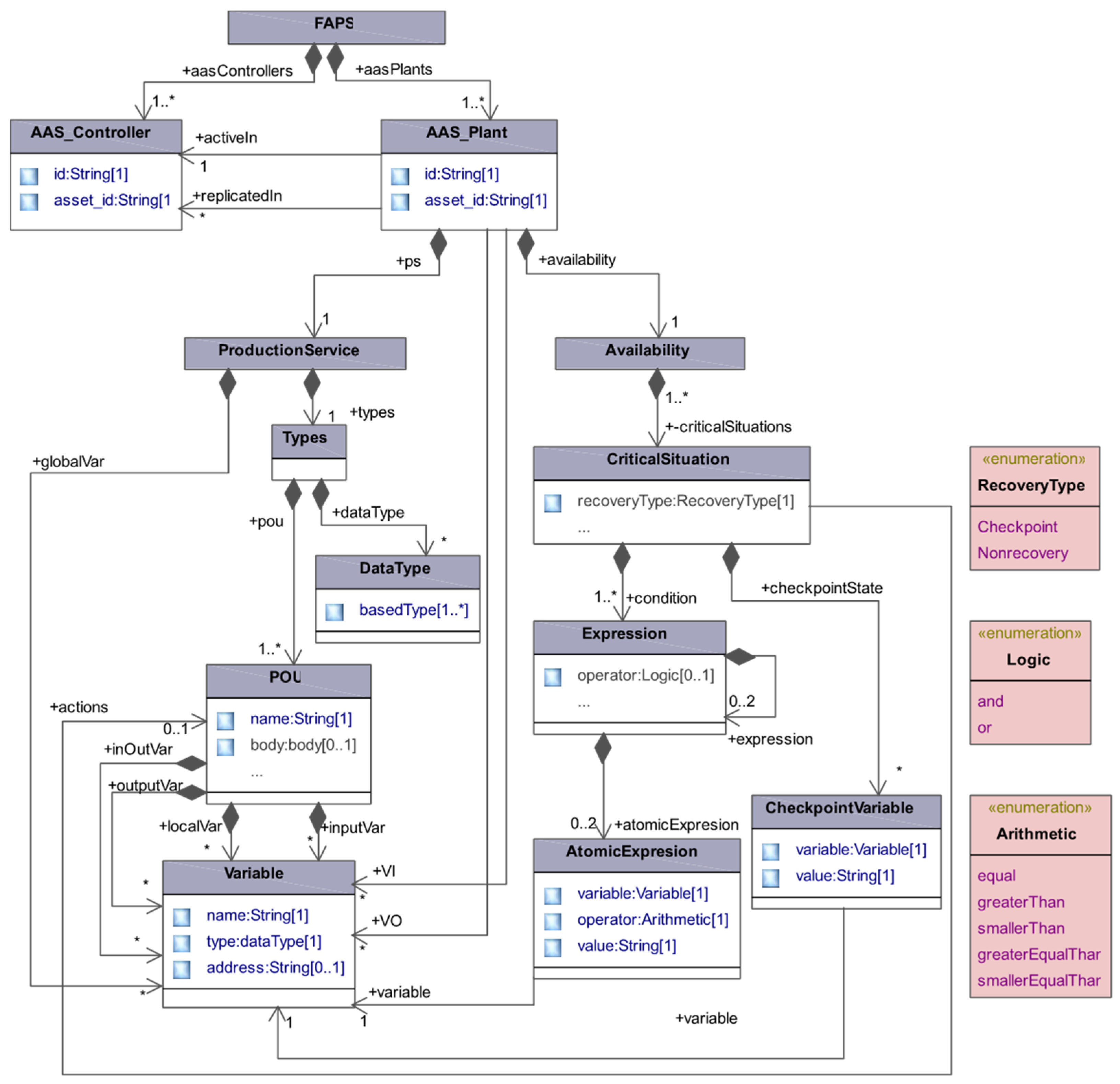
  • The Asset is a physical or a logical object owned by or under the custodial duties of an organization, having either a perceived or actual value to the organization.
  • The Asset Administration Shell (AAS) is the digitalization of an asset. In other words, and AAS is the interface that connects the physical asset through I4.0 communications such as OPC Unified Architecture (OPC UA) [31]. It is also in charge of offering the I4.0 component’s services to the Industry 4.0 (e.g., [32] presents an AAS model able to represent International Electrotechnical Commission (IEC) 61131-3 standard compliant programs and the relevant relationships with Programmable Logic Controllers and each device of the controlled plant). According to the glossary of Platform Industrie 4.0 [33], the AAS concept can be directly related to the concept of Digital Twin (DT). However, several works in the literature apply the DT concept to refer exclusively to highly accurate simulation models. In the authors’ understanding, both meanings are correct as both, in different ways, are related to the Asset behavior. In this work, the first one applies.
Following this concept, Automation Production Systems (APSs) could be viewed as a set of two types of I4.0 connected Components: (1) Controller and (2) Plant, which offer production services. Their main features are the following:
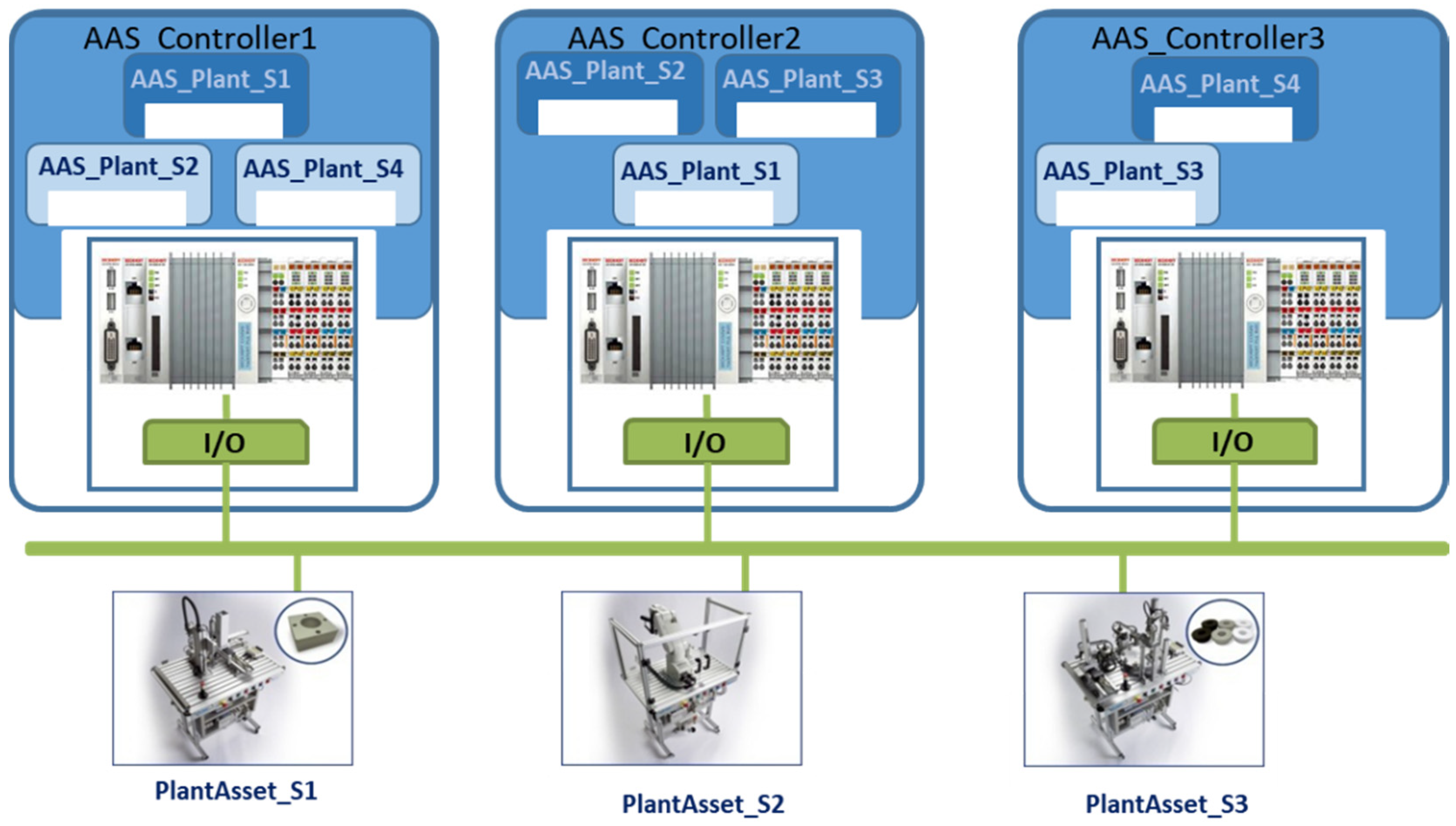
  • Controller I4.0 Component:
    Asset (ControllerAsset): The Programmable Logic Controller (PLC), the primary controller for such type of systems, and the I/O boards;
    AAS (AAS_Controller): automatizes the production by means of its I/Os.
  • Plant I4.0 Component:
    Asset (PlantAsset): physical station and the sensors and actuators connected to controller’s I/Os;
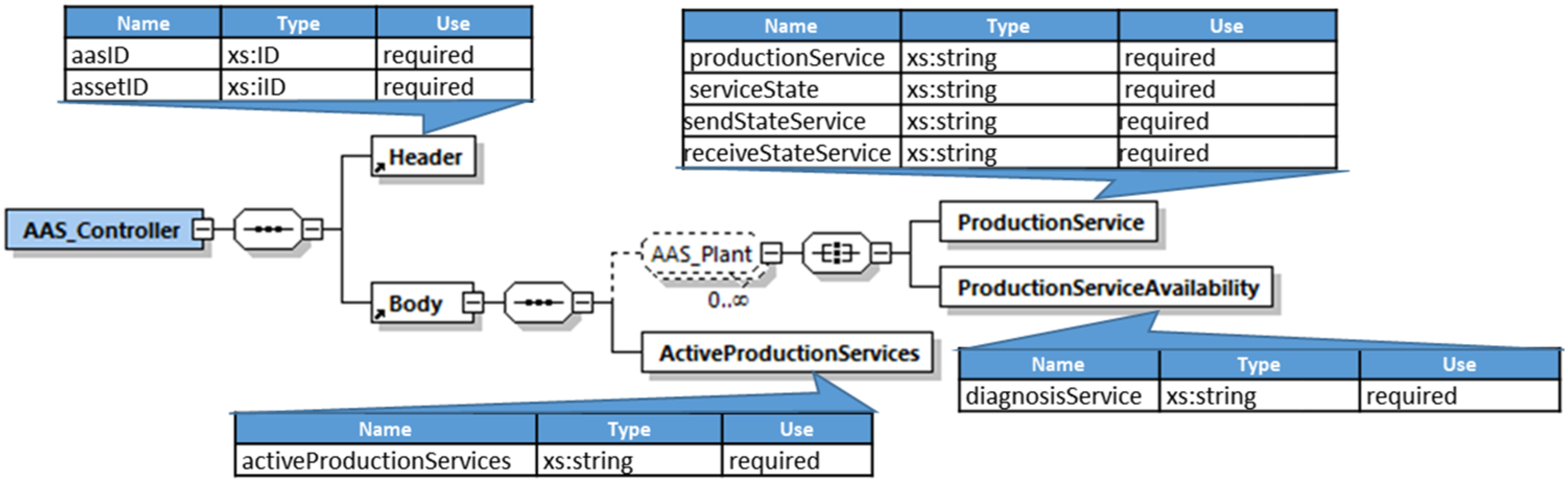
    AAS (AAS_Plant): offers a production service (which contains the control logic and data).
This work goes a step further, and it defines Flexible Automation Production Systems (FAPSs) as those APSs that support flexibility through reconfiguration according to QoS parameters, such as control system availability in the event of controller failure or workload balancing. Hence, this work provides support for developing flexible applications at production level, using PLCs as primary controllers. To achieve this, during the design of the FAPSs it must be stated which controllers can potentially automate the production of every PlantAsset in order to download the corresponding Control Logic Software Module (a Program Organization Unit—POU- if IEC 61131-3 standard [34] is used). The runtime platform manages the execution of every control software module (henceforth Production Service-PS-), ensuring that it is only running in a unique controller of the system (active controller), and the others acting as tracking controllers. Besides, applying dynamic reconfiguration to assure specific QoS (e.g., availability of the control system, efficient use of resources or any other QoS), implies both QoS supervision (by means of mechanisms like heartbeat or workload, respectively, in all controllers) and guaranteeing reconfiguration feasibility, avoiding unpredictable effects in the manufacturing process. Therefore, during the design phase, it is also necessary to define those critical situations in which the state of the PlantAsset is not known and thus, the reconfiguration is not possible.
Figure 1 depicts the general scenario of a FAPS in terms of I4.0 Components. This seeks to prove the capability to assure work balance among the distributed controllers (AAS_Controller1…AAS_Controller3) comprising the automation system for a flexible manufacturing cell which is composed by three stations (PlantAsset_S1…PlantAsset_S3). As observed, AAS_Controllers, as composed AASs, contain a set of AAS_Plants. In this example, the software control code of S1 (AASPlant_S1) can be run in either controller 1 or controller 2, but it is only active in controller 1.
The structure of AASs is defined in [35]. Following this recommendation, Figure 2. illustrates the general structure proposed for the AAS_Controller, which has two main parts: Header and Body. The Body has two submodels per AAS_Plant contained (ProductionService and ProductionService Availability) and the ActiveProductionServices submodel that collects the list of ProductionServices which are being executed in the corresponding ControllerAsset.
Production Service submodels are characterized by four properties: The service offered by the corresponding AAS_Plant (ProductionService); a set of variables that characterize the state of such production service (Service State); and two functions to send or receive the values of the variables that collect the execution state. Active controllers send at the end of the execution cycle the current execution state (SendStateService) and those controllers which are tracking receive this state (ReceiveStateService). Hence, if an active controller fails all tracking controllers have the last known state.
Production Service Availability submodels have a unique property for runtime diagnosis. Thus, this function indicates if the current state of the PlantAsset can be derived from the current values of the controller variables or not. To perform such diagnosis this function processes the set of critical situations detailed during the design phase. At runtime, a PlantAsset could be in the following states or situations:
  • non-critical situations: the automation system is aware of the current process state. Therefore, it is possible to activate ProductionServices in another PLC (after de-activation in the current controller or after a controller failure), using as their initial state the last known state of the interrupted ProductionService;
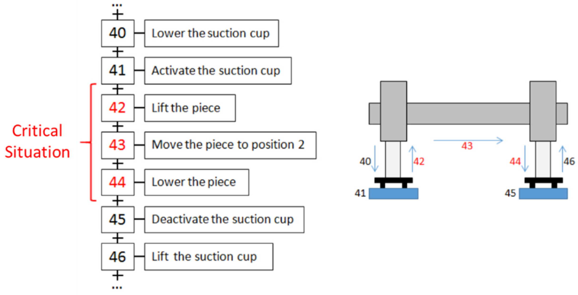
  • critical situations: the automation system does not know exactly the current state of the ProductionServices. Therefore, as it can lead to unpredictable process behavior, the activation/de-activation of ProductionServices is inhibited in critical situations. For example, when a controller fails, it has to be analyzed if all its active ProductionServices can be recovered, on a tracking controller, in a previous known state (checkpoint). In the case of a non-recoverable situation, it is analyzed if the ProductionService must be safely stopped and the operator warned. Figure 3 depicts a simple but illustrative example of a ProductionService for the movement of a piece by a crane. While the crane is lifting, transporting or placing the piece, the ProductionService cannot be de-activated as the piece may be released which prevents the production from continuing. Therefore, the state of the ProductionService during these operations is denoted as critical and in such case, reconfiguration cannot be performed. The rest of the states are denoted as non-critical.

2.2. Flexible Automation Middleware (FAM)

This subsection summarizes the agent-based middleware architecture for flexible automation production systems proposed by the authors in [26]. The general scenario is illustrated in Figure 4.
FAM includes four agent types: two are part of the generic and basic architecture, whereas the other two are application dependent. Generic agents are able of managing different QoS:
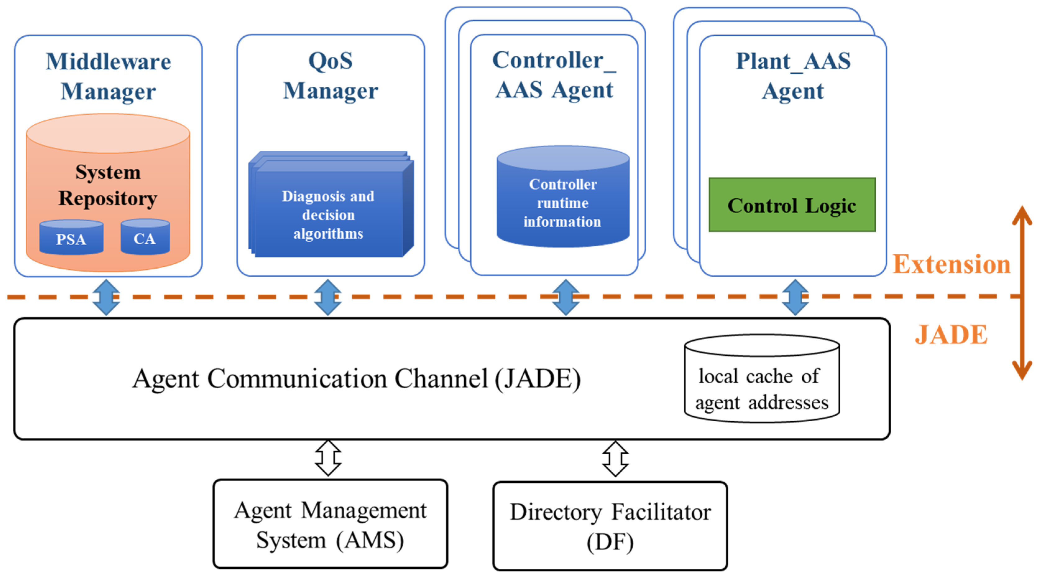
  • The Middleware Manager (MM) is the main orchestrator. It is a unique agent in charge of managing the System Repository (SR): a dynamic model that contains information about the current state of the automation application, which changes over time.
  • The QoS Manager comprises a set of agents responsible for QoS fulfilment.
    • QoS Monitor (QM) agents are responsible for monitoring the specific QoS to be handled, generating triggers if they detect QoS losses. Hence, there are as many QMs as QoS to be met.
    • The Diagnosis & Decision (D&D) agent is unique in the system and it is responsible for launching diagnosis and decision algorithms as well as reconfiguration events.
As commented above, the rest of agents in the system depend on the automation application. Applied to this work they implement both Plant_AAS and Controller_AAS assuring the availability. These agents guarantee the distributed intelligence, as their role is to collect information from the current state of the automation system as well as performing reconfiguration decided by the D&D:
3.
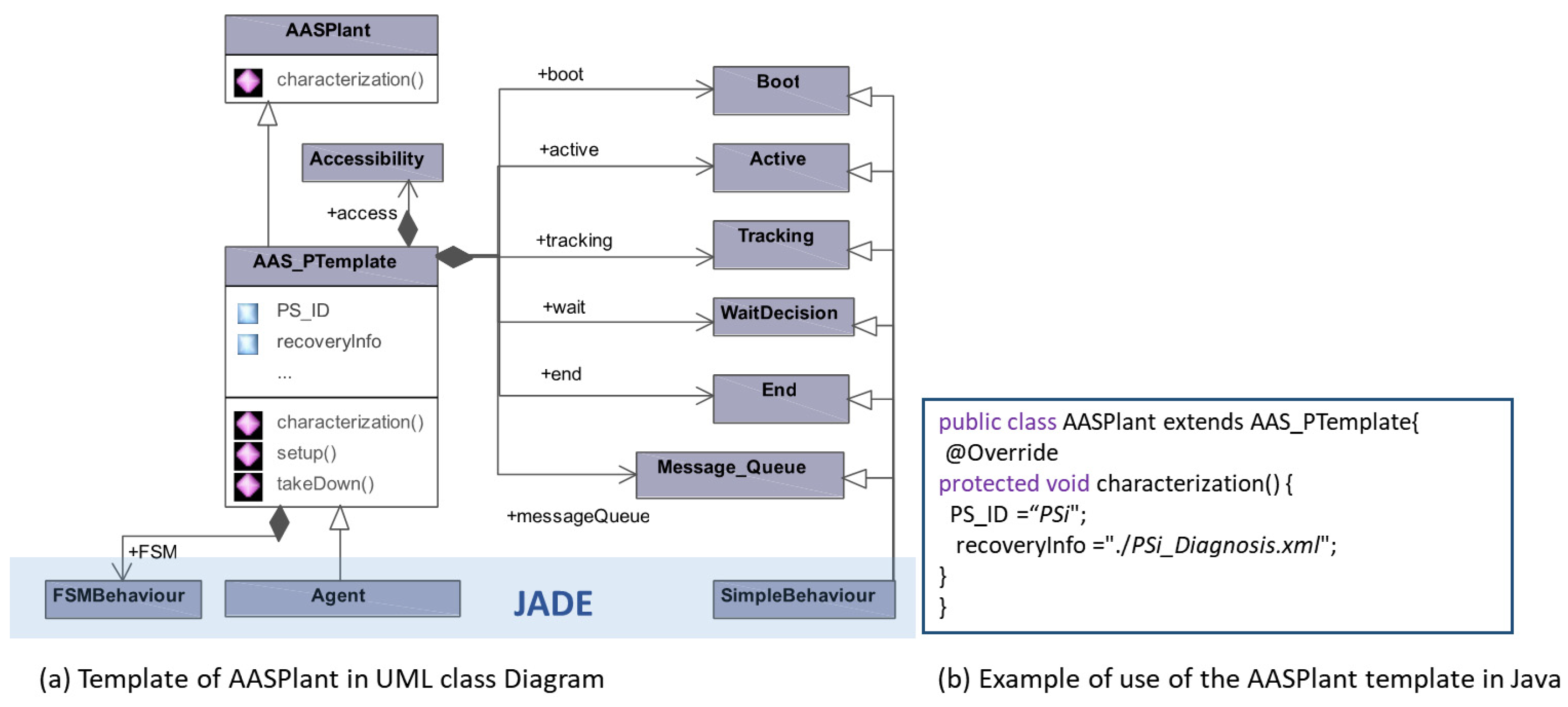
The Plant_AAS Agent (APlant_AAS) manages the execution of the corresponding ProductionService’s actions as well as collects, transmits, stores and makes diagnosis on the current state of this. The Component Manager of a APlant_AAS is implemented by a Finite State Machine that represents the possible states of the ProductionService lifecycle (detailed description can be found in [26]). Although each ProductionService can be replicated in a number of controllers, at runtime only one controller will be executing the ProductionService and its corresponding APlant_AAS will be in active state. For the rest of the controllers, the ProductionService is not executing and their corresponding APlant_AASs will be in tracking state.
4.
The Controller_AAS Agent (AController_AAS) registers its corresponding controller and the associated resources in the System Repository when the controller joins the system. It also registers itself in the Directory Facilitator of JADE offering as services the set of ProductionServices that can run in the controller. Finally, it launches its corresponding APlant_AASs. There are as many AController_AAS as controllers in the system.

2.3. Model Driven Engineering for Modeling Flexible Automation Production Systems

This subsection illustrates how Model Driven Design has been adopted for designing and developing automation systems. In fact, it has been used for both characterization purposes (from the definition of system parts, such as QoS requirements, to the overall system description) and implementation purposes. In the concrete case of industrial automation field, model-based techniques are integrated into the development process. Several works base on the use of the Unified Modeling Language (UML [36]) to describe control systems based on the IEC 61131 [37,38] and the IEC 61499 [39,40] standards. The Systems Modeling Language (SysML [41]) has been also applied [39,42], whereas other works also use modeling techniques and design patterns [43] or aspects [44]. Furthermore, the worldwide PLCopen association, which is vendor and product-independent, has specified a common representation format for the software model of the IEC 61131-3 standard [45,46]. The objective is twofold. On the one hand, it is aimed at achieving programming tools interoperability. On the other hand, it also supports a model-based definition of the application software of automation systems.
Other authors go a step further and make use of modeling techniques for supporting the development of the overall automation system. The “3 + 1” architecture proposed by Thramboulidis [47] allows the system design based on three models (software engineering, mechanical engineering and electrical engineering) linked through the “+1” model, which in the end conforms the whole system. Another example is the MDD approach proposed in [37,48], which uses the UML profile technique to define domain languages. Additionally, it also allows the automatic generation of the software architecture in PLCopen XML format, using functional code imported from PLC libraries. Similarly, authors in [49] define the so-called SysML-AT, a specialized profile that is integrated into the German commercial tool CoDeSys, and that allows the definition of the hardware and software of the automation and control systems.
Models have been also used to consider system reconfiguration as an extension of the definition of system elements, such as Function Blocks (FB), machines, controllers or components. This is the case of the Functional Application Design for Distributed Automation Systems (FAVA) research project [43,50], which proposes including resource demands within the software view (amount of memory and number of bytes exchanged with other FBs) with the aim to be used at the deployment of the FBs.
The model-based approach presented in [51] considers both functional and non-functional requirements in terms of constraints related to the different views of the production automation system. It covers from sensors or actuators to the whole plant, including a tolerance model with traceability purposes. In fact, the information contained in this model is used by an agent system for analyzing if reliability demands can be maintained, and whether the needed probability of a concrete quality will be reached. Non-functional requirements are also tackled at the AMoDE-RT approach [44], but as an aspect-based characterization related to the functional components. As a result, non-functional demands can be supervised at runtime, being possible to reconfigure the system in the event of non-fulfillment. The approach is applied in [42] to embedded control systems.
The holonic architecture at the SOCRADES project [52] performs runtime distribution of machine job, through a model-based definition of the functionalities of a machine. The modeling approach described in [53] allows the specification of the operations performed by the machines within a plant as well as the operations required for a product manufacturing. This information is used to automatically derive an optimal operation sequence.
All research works commented above demonstrate the usefulness of MDE in automation field for different purposes, as all of them have in common that the use of models helps managing the complex automation systems [54,55]. This work uses MDE in order to design and develop Flexible Automation Production Systems, which are complex systems due to their size, functionality and distribution. In fact, MDE relies on models and model transformations for automating the software development process. More precisely, there are Model to Model (M2M) transformations as well as Model to Text (M2T) transformations. In both cases, the input refers to a model that conforms to a meta-model whereas the generated output is related to a new model conforming to another meta-model or source code, respectively.
The authors propose the Meta-Model illustrated in Figure 5, which collects all the information for defining FAPSs. The framework proposed by the authors implements this Meta-Model in a Markup Language file. This model is the input of the: (1) M2M transformation rules to generate as many flexible automation projects as controllers in the system, in PLCopen XML format; (2) M2T transformation rules to generate the code of APlant_AASs and AController_AASs in PLCopen XML format. The Technical Committee six of PLCopen defines a meta-model in a ML notation (XML Schema) for the IEC 61131-3 standard software model. This ensures that the M2M transformation produces models following the PLCopen meta-model.

3. Results

This section presents a MDE based framework that generates: (1) a flexible automation project per PLC of the FAPS; and (2) a set of application dependent agents (APlant_AASs and AController_AASs). Additionally, in order to make FAM generic and customizable, this work defines the templates for these types of agents which are customized with application dependent information. As commented above, these results are achieved applying a set of M2M and M2T transformation rules to a Model that must be specified since the design phase following the meta-model depicted in Figure 5.
The general scenario of the proposed framework is illustrated in Figure 6. It is based on two automation standards: PLCopen [46] and AutomationML [56,57]. FAM is composed of two core elements: (1) The FAPS Model Editor, and (2) the code generator. As previously commented, two different outcomes are obtained from code generation: on the one hand, the Flexible Automation Projects, which are composed by the set of ProductionServices the PLC can run, as well as the activation/de-activation code and the recovery actions; on the other hand, the code corresponding to the application agents.
The following subsections detail the FAPS Model Editor as well as the code generators, which are based upon M2M and M2T transformations, respectively. As the input for these transformations (i.e., the outcome from the FAPS Model Editor) is in XML, the identified transformation rules will be implemented by using XML stylesheet technology [58].

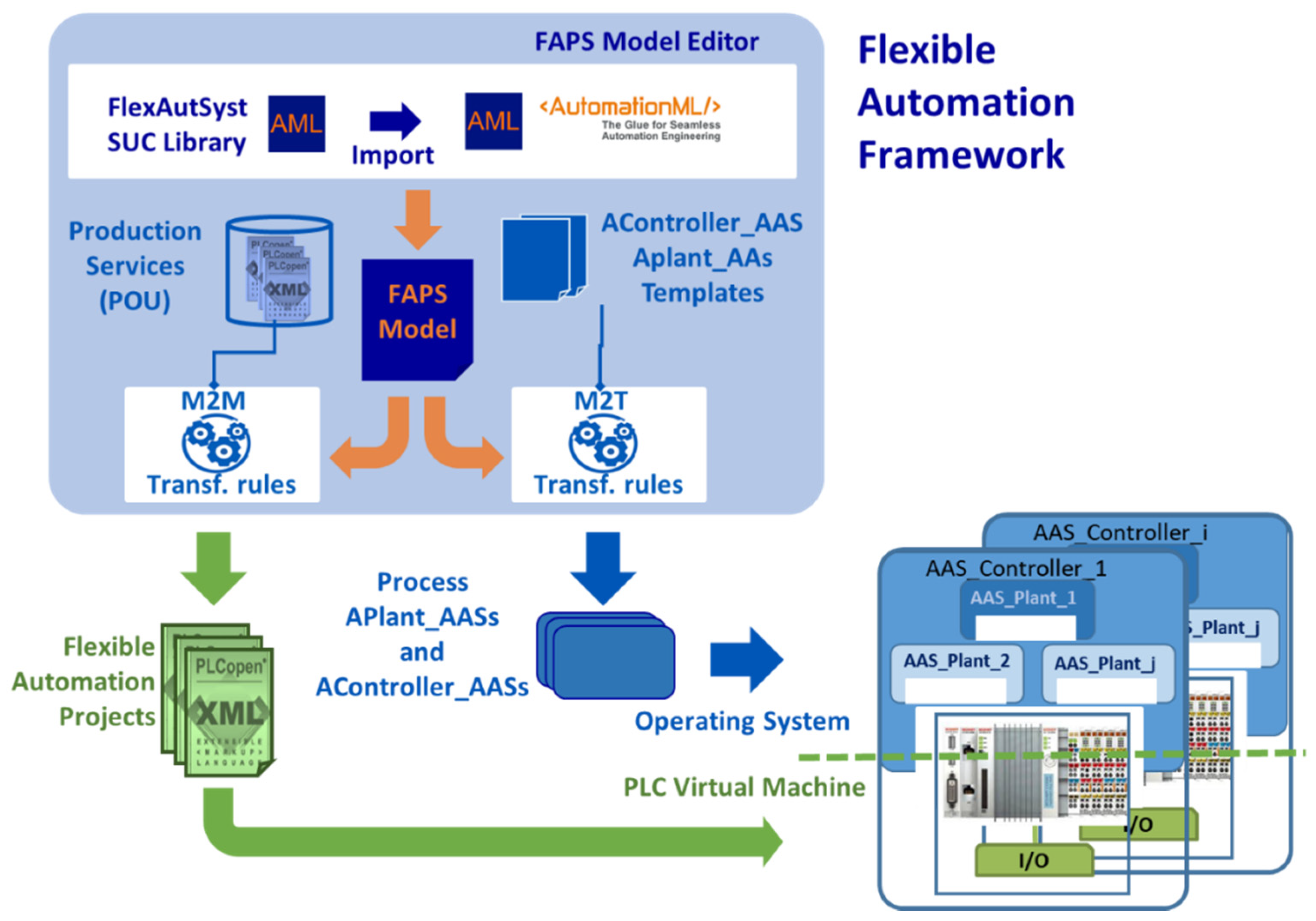
3.1. FAPS Model Editor

The design and development of the automation system must be structured in Production Services, which, by means of I/Os and their control logic as a set of POUs and variables, control different stages of the process. The POUs of the control logic can be generated directly in a PLC programming tool or following the guidelines provided in [48] or [49]. ProductionServices are duplicated in different controllers (replicatedIn in Figure 5). Moreover, each AAS_Plant is characterized by a set of critical situations that refer to situations at which ProductionService cannot be reconfigured. Critical situations are defined by a condition to be met, which is defined as logical expressions of ProductionService variables. For instance, in the event of a controller failure, the continuity of the automation system execution must be analyzed, resulting in two alternative outcomes: (1) the normal execution can be restored by means of recovery actions, taking the system to a known previous state (checkpoint); (2) the failure is not recoverable, and thus a safe stop action is required.
The FAPS Model Editor provides support to developers for designing automation systems. This tool follows the guidelines of [59] to implement the meta-model of Figure 5 using the Computer Aided Engineering eXchange (CAEX) [60] libraries of AutomationML:
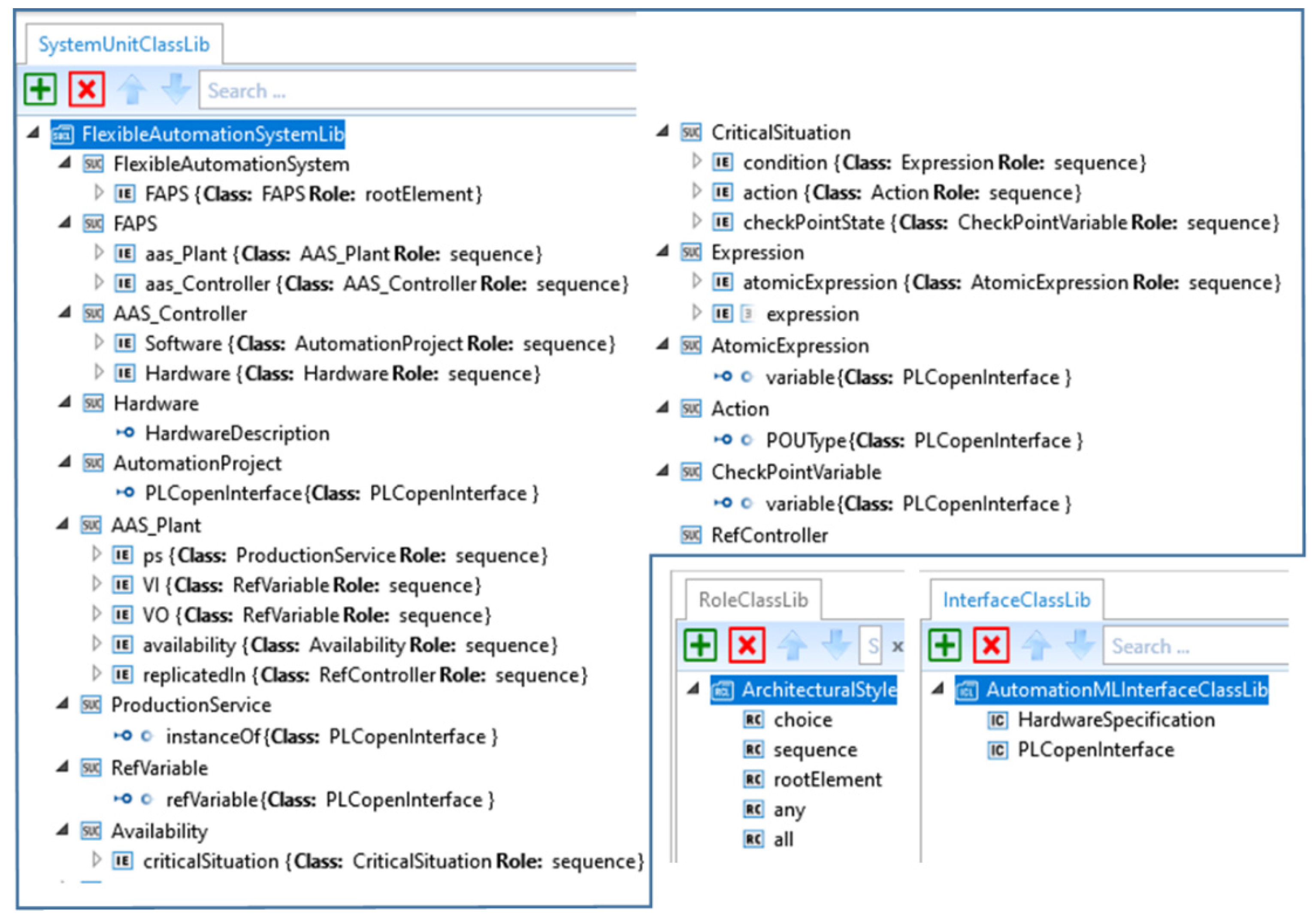
  • The System Unit Class Library indicates the concepts required to define a flexible automation system. It comprises the so-called System Unit Classes (SUC), which represent the elements of the meta-model. The SUCs are characterized by their attributes. As the elements in the system can be simple or complex (i.e., composed of internal elements), the SUCs representing them can be either simple or complex. The complex SUCs comprise instances of other previously defined SUCs.
  • The Interface Class Library offers interfaces that enable the association of a SUC (simple or complex) to an element on an external file. This library provides a PLCopen interface included in AML which grants access to the POUs and variables within a PLCopen automation project. It also includes the hardware interface, a new interface added to allow the definition of the controllers and automation projects in PLCopen.
  • The Role Class Library provides the different roles by which the elements can be organized in the model (choice, sequence, each and every role). The ramifications of the structures based on these roles is settled by means of their attributes minOccurs and maxOccurs.
Further details regarding these libraries and their specifications can be checked in [59].
These libraries are integrated into the AML editor (see FlexibleAutomationSystem SUC library in Figure 7). This allows to use this tool to define FAPS models. Every Internal Element (IE in Figure 7) is an object whose Class corresponds to another SUC of the library. The basic attributes of the AAS_Plant are its id, asset_id and the reference to the controller in which the control logic is active (activeIn) as well as the latent controllers (replicatedIn). This definition is completed with links to POUs and global variables. This latter is a sequence of critical situations which are defined making use of expressions involving variables.
As an example, the definition of the AAS_Plant named ST1 is depicted in Figure 8.
Besides, the FAPS Model Editor allows the characterization of the critical situations of PSs. To that end, the developers must conform boolean expressions to evaluate checkpoint or unrecoverable critical situations from arithmetic and logical operations with the available variables. In the same way, the recovery actions to be performed at each checkpoint state (i.e., the values of the variables that define the checkpoint state), can be declared at this point, if needed. Figure 8 presents the definition of the expression: “(Control_ST1.Sequence1_1.E23.Q1 = 1 AND Control_ST1.Insert_P1.E73.Q1 = 1)” using the AML editor.

3.2. Flexible Automation Projects Code Generator

The code generation of Flexible Automation Project covers normal operation as well as reconfiguration needs. As current IEC 61131-3 standard execution environments do not support dynamic code deployment, the reconfiguration requires the de-activation of a Production Service in a controller and its activation in another one. Therefore, the generated automation projects not only contain all the Production Service POUs that the controller can run, but they are enhanced with a wrapper that allows the APlant_AASs to activate/deactivate their execution. In addition, these projects also include the code to read/write the state of the Production Service of each APlant_AAS.
The APlant_AAS interacts with its associated Production Service through a predefined area of the controller memory. To that end, specific libraries are required depending on the manufacturer (e.g., S7-300 controllers from the German manufacturer Siemens require from libnodave and s7netplus libraries to enable an external access [61,62], whereas the Automation Device Specification, or ADS, is required in Beckhoff controllers for that purpose [63]).
To sum up, the Flexible Automation Projects include both the code endorsing the Production Services and the control code that supports their flexibility (see ProductionService submodel in Figure 2. Hence, each Production Service (PS) module is composed of three different POUs:
  • ProductionService_id: a program to control the execution of the Production Service (PS_id);
  • SendStateService_id: a program that reads and serializes the state variables of the production service;
  • ReceiveStateService_id: a program that de-serializes the received information and updates de state variables of the production service with new initialization values in case it changes from tracking to active in a controller.

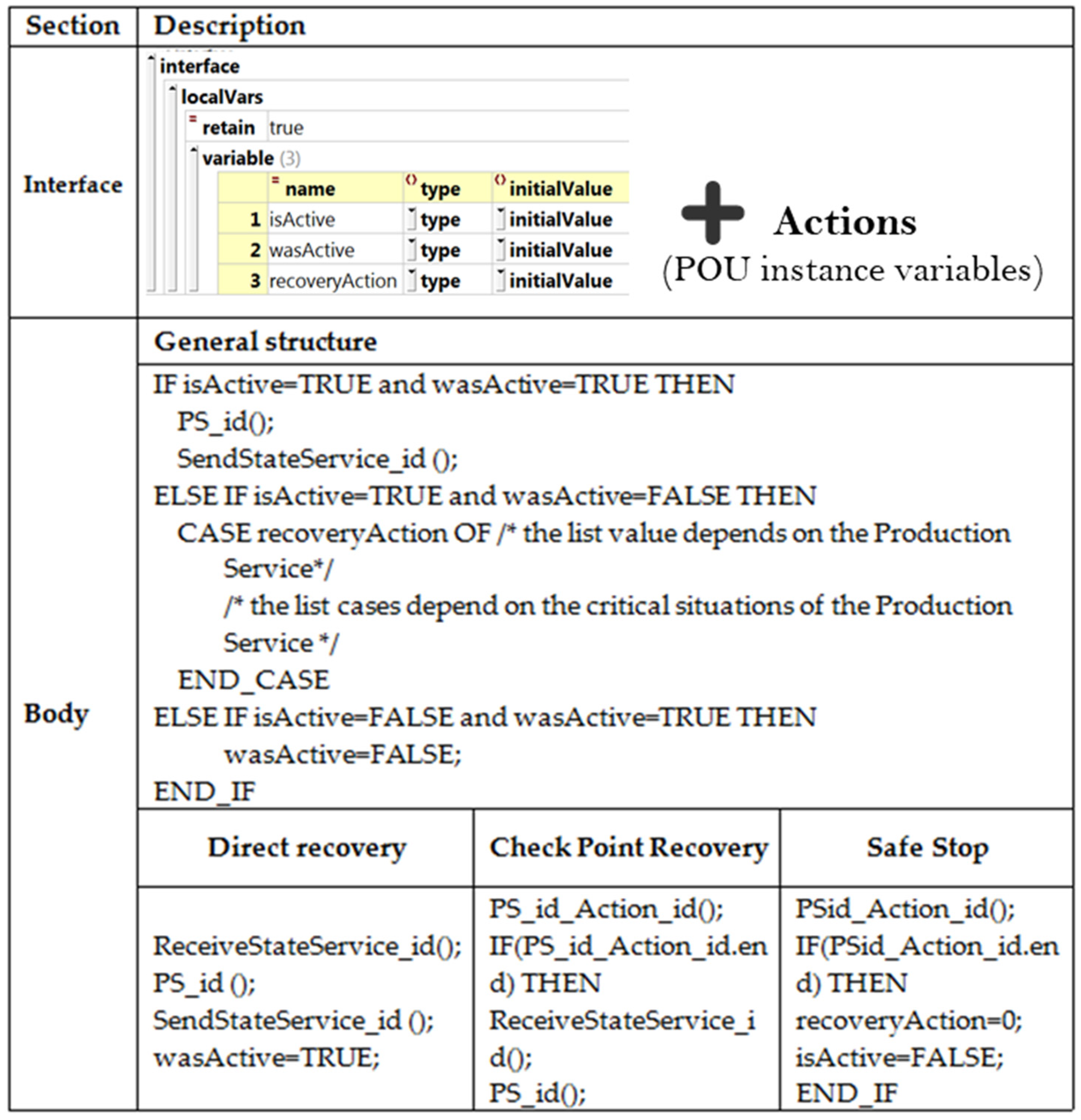
3.2.1. Production Service Program

Thanks to this program, the APlant_AAS can manage its corresponding PS, as it provides the external access required to activate/deactivate the execution of the logic and recovery/stop actions.
The program structure and the templates to be fulfilled by the generator are depicted in Figure 9. The program interface is a set of application dependent variables and other local static variables that allow APlant_AAS to manage it. These local variables are:
  • isActive and wasActive: these boolean variables determine the activation/deactivation of the logic.
Two further local variables are included to support the availability:
  • recoveryAction: it is related to the coded actions required to manage a concrete critical situation if necessary.
  • Action_CriticalSituationID: it identifies a specific recovery code (POU instance).
This program is automatically generated from FAPS model by M2M transformation rules. Three transformation rules have been developed: one for generating the Interface of such POU; other for its functionality (Body) and the third for the recovery actions:
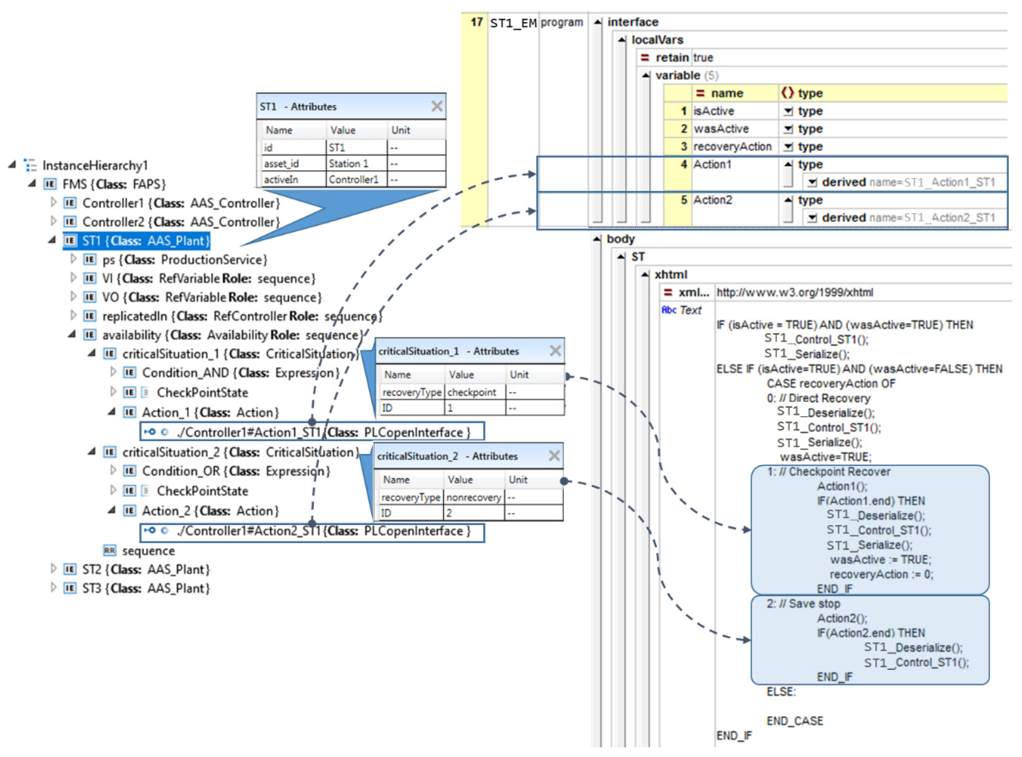
  • Rule 1—Interface definition: It is applied to every InternalElement having RefBaseSystemUnitPath property with AAS_Plant value. The rule starts adding the common part with the fixed local variables at their initial values. After, it adds as many POU instance variables as actions defined in the CriticalSituation elements. For this, it searches those inherited InternalElements that have RefBaseSystemUnitPath property with Action, getting the value of its ExternalInterface. This will be the type of the new added variable. The name will be the same as the InternalElement’s name.
  • Rule 2—Body: It is applied to every InternalElement having RefBaseSystemUnitPath property with AAS_Plant value. The common minimal structure is initially added (See Figure 9), changing PS_id() by the name of the ExternalElement in a POUInstance. Furthermore, this template applies Rule 3 to complete the list of the possible causes related to the activation of a Production Service.
  • Rule 3—Recovery Actions: It is applied to InternalElements that have RefBaseSystemUnitPath property with CriticalSituation value. The code to add depends on the value of the recoveryType property (see Figure 9). The PS_id() is customized following the procedure commented above.
Figure 10 exemplifies the generation process for the control program corresponding of a Production Service (CL1_ST_Control). The left side of the figure presents the flexible model through which the developer defines the flexible manufacturing system, while the right one shows the resultant program, ProductionService_id, in PLCopen XML format.

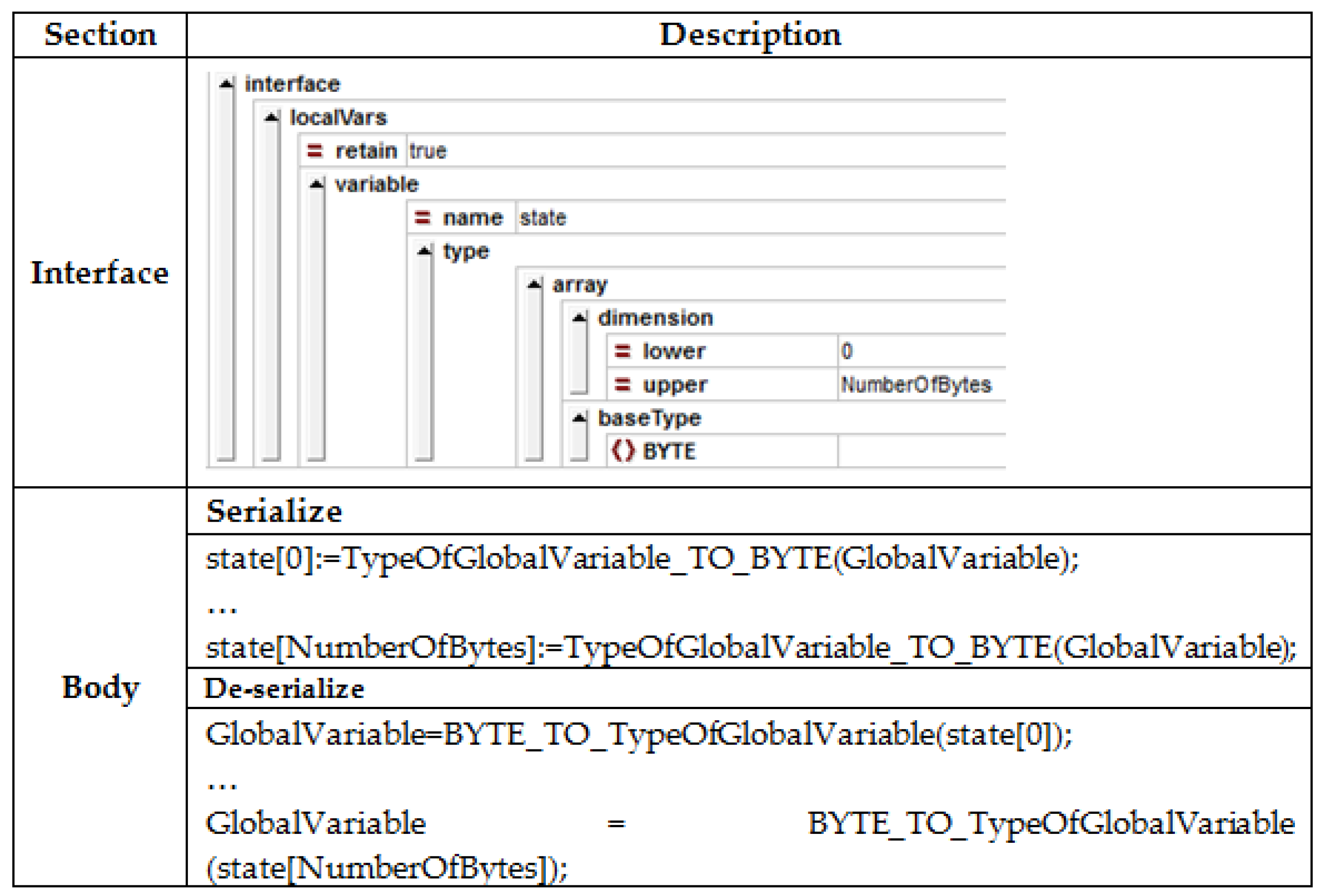
3.2.2. Serialization Programs

The serialization program (SendStateService_id) collects the values of the state variables into a byte array, which is accessible by the APlant_AAS. Byte array is selected due to most IEC 61131-3 environments endorse transformation functions to cast any data type to byte (e.g., INT_TO_BYTE, BOOL_TO_BYTE, etc.).
On the contrary, the de-serialization program (ReceiveStateService_id) process the array sent by the APlant_AAS and updates the state of the production service.
The structure and the templates to be fulfilled by the generator are depicted in order to generate SendStateService_id and ReceiveStateService_id programs are depicted in Figure 11.
These programs are automatically generated from FAPS model by M2M transformation rules. Three transformation rules have been developed: one for generating the Interface of such POUs; other for serialization functionality (Body) and the third for the de-serialization body:
  • Rule1—Interface Definition: It is applied to every InternalElement having RefBaseSystemUnitPath property with POUInstance. It initially calculates the number of bytes needed for defining the state (NumberOfBytes of Figure 11). For this, local and global variables as well as input and output parameters of the POU that implements the control logic of Production Service are identified. This POU is located in the name of the ExternalElement. Then, Rule 2 and Rule 3 are applied in order to generate the body of serialize or deserialize, respectively.
  • Rule 2—Serialize Body. It requires the Production Service’s state and its corresponding variables (see Figure 11).
  • Rule 3—De-Serialize Body: It also requires the state and the related variables, resulting in the writing of the new state (see Figure 11).
An example of FAP generation containing the POUs, data types, global variables and tasks associated to three Production Services (ST1–ST3) is presented in Figure 12.

3.3. Application Dependant Agents Code Generator

In order to make FAM generic and customizable, this paper proposes templates for the application agents, that can be customized for specific processes. The following subsections detail such templates and the automatic generation of APlant_AASs and AController_AASs.

3.3.1. APlant_AAS Template

Each APlant_AAS is associated to several Production Services hosted in different PLCs and it performs state diagnosis, when required, for determining if the current state indicates a critical situation. The APlant_AAS template (AAS_PTemplate) proposed by the authors, presented in Figure 13, addresses this issue offering a generic and customizable solution.
The template can be customized by means of two parameters:
  • PS_ID: this parameter contains an identifier that can match the identifier of the automation project, and that identifies each Program Organization Unit.
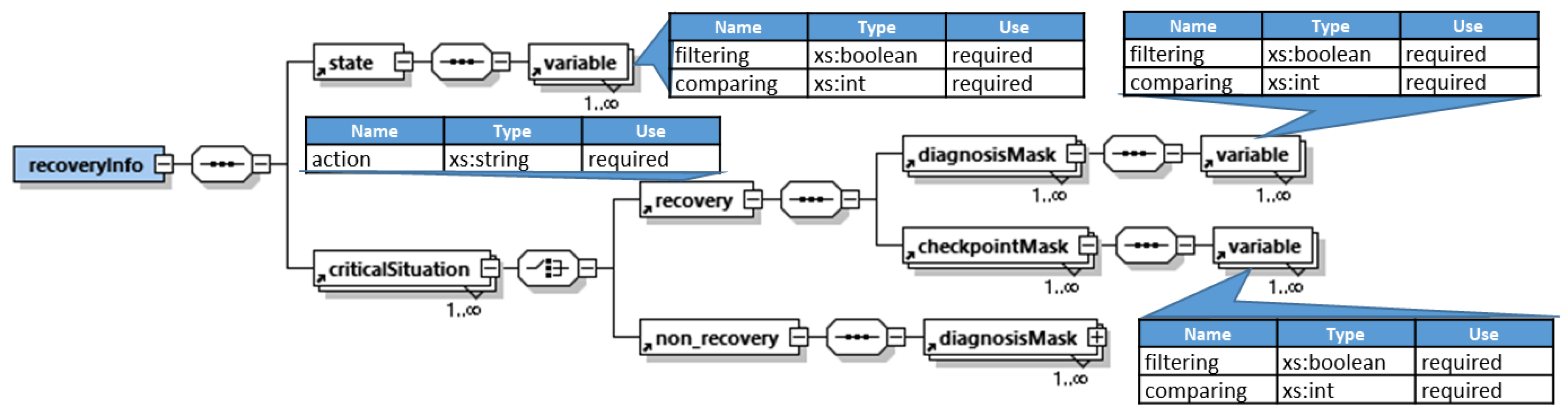
  • recoveryInfo: it contains the set of masks to be applied to each component to determine which type of operation must be applied at any moment. These masks, defined following the meta-model presented in Figure 14, allow to identify the critical situations of the Production System (e.g., the manufacturing steps 42–44 from Figure 3 are identified as critical situations based on the information in the recoveryInfo parameter). The Diagnosis XML file has been conceived to ease the generation and storage of such information with a predefined structure. This file stores information about the state variables (name and type), and the masks to perform both the diagnosis and the checkpoint. Note, that the diagnosis masks determine if it is a critical state type (checkpoint or unrecoverable) by filtering the state variables related to the condition to be diagnosed.
The Component Manager of APlant_AAS has been implemented in a FSM as established in [26], which consists of the Boot, Active, Tracking, Wait decision and End states. This FSM is implemented as a JADE FSM. There are two JADE behaviors (Simple Behaviour) associated to each FSM state: one that manages the message exchange with the middleware agents (Message_Queue), and another one to implement the specific functionality of each state (Boot, Active, Tracking, WaitDecision and End). Meanwhile, access provides access to the PS’s code in the PLC.

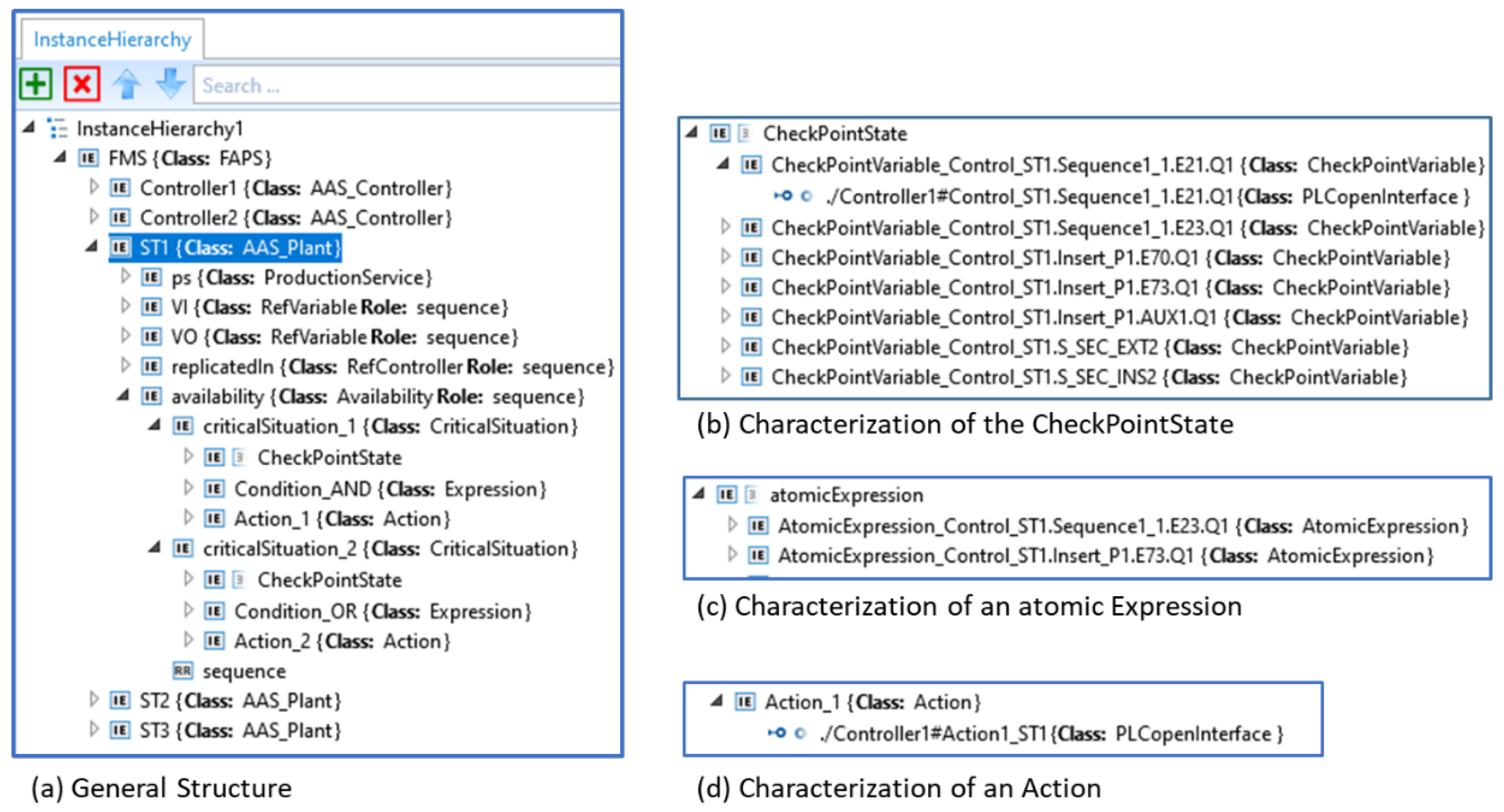
3.3.2. APlant_AAS Generation

The transformation of critical situations related information into a set of masks to diagnose the Production Service is a major issue in APlant_AAS generation.
To generate PSid_Diagnosis.xml file from FAPS model the following transformation rules are required:
  • Rule 1—State characterization: It generates the set of variables conforming the state. To do this, every InternalElement having RefBaseSystemUnitPath property with RefVariable and the InternalElement having RefBaseSystemUnitPath property with POUinstance in AAS_Plant are processed.
  • Rule 2—Critical Situation: It applies to the InternalElements that have RefBaseSystemUnitPath property with CriticalSituation in an AAS_Plant. As a result, the Critical Situation information stored in diagnosis XML file is generated.
  • Rule 3—Diagnosis: It processes the Condition to identify which the state variables are required to determine the type of critical state at that situation. This rule applies to every InternalElement with RefBaseSystemUnitPath property having an Expression in a CriticalSituation.
  • Rule 4—Checkpoint: It processes the CheckpointState to determine at which condition the AAS_Plant must be restarted. This rule applies to each InternalElement that have RefBaseSystemUnitPath property with CheckPointVariable in a Critical Interval.

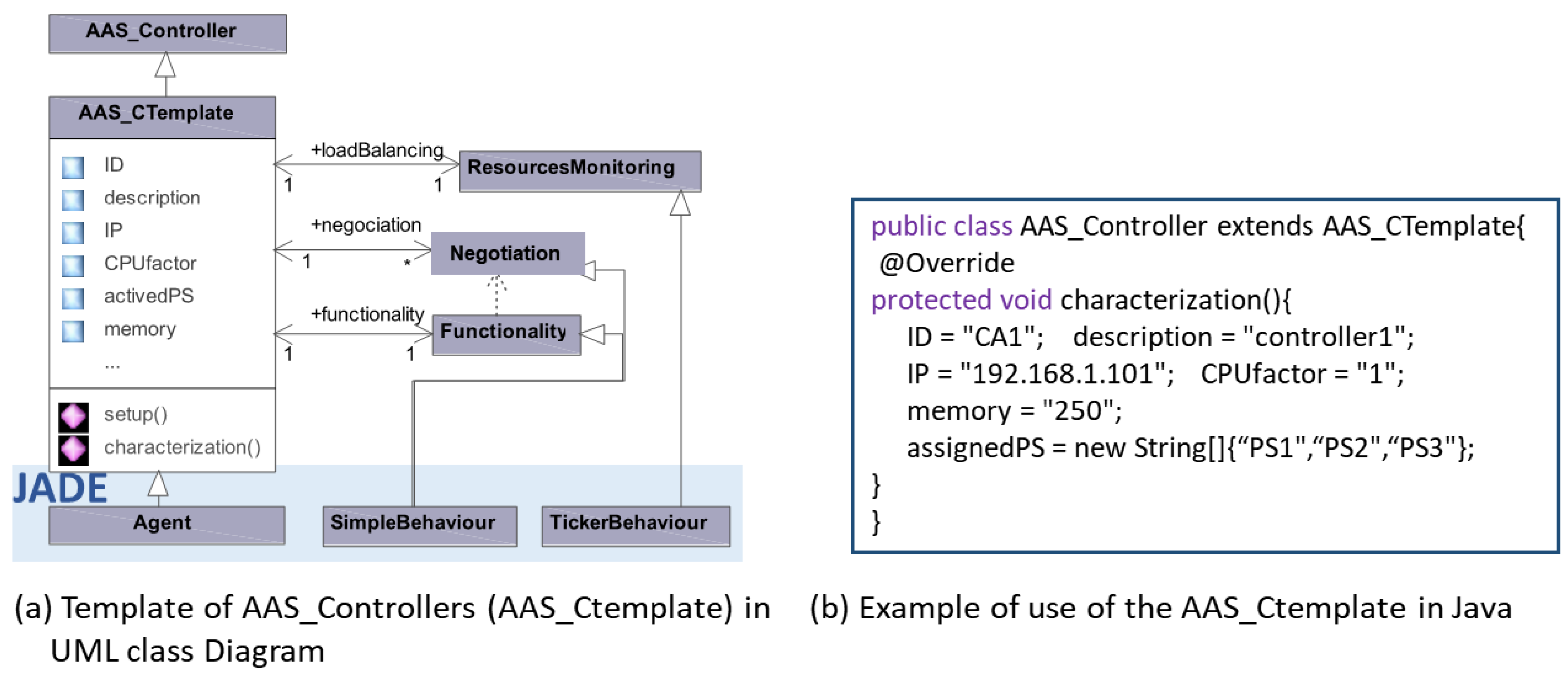
3.3.3. AController_AAS Template

The AController_AAS updates the information related to the state of the controller resources required by QoS Monitor agents. They can participate in negotiation processes when needed. Negotiation criterion depends on the specific QoS. For instance, in Availability and after a controller failure, the D&D agent will require a negotiation process among controllers able to run the affected Production Services, being the specific criterion, for example, the minimum execution cycle.
In order to offer a generic and customizable solution, the AController_AAS template (AAS_CTemplate) illustrated in Figure 15 is proposed. The template has a set of customizable parameters:
  • ID, which identifies the agent in the system;
  • A textual Description;
  • CPUfactor, with respect to a reference controller;
  • Memory resources;
  • IP address;
  • AssignedPS: a list of Production Services, whose control logic is executed in the controller.
The Class Diagram presented in Figure 15 defines the template for the design and parameterization of every AController_AAS of the system. The basic functionality of the AController_AAS, which manages the messages from the middleware agents, is implemented in a cyclic behavior (functionality). These messages can be either negotiation messages or queries about the controller resources. Each time a negotiation message is received, a new negotiation behavior is instantiated. This behavior is deleted once the negotiation process, it was related to, is concluded. Furthermore, the AController_AAS can also implement resource monitoring behaviors. These behaviors allow monitoring a specific resource of the controller as part of the QoS monitoring process.
The registration of the AController_AAS and the creation of resource monitoring and functionality behaviors are performed during the setup method of the AController_AAS.

4. Assessment

The modeling approach and the application agents presented in the previous section have been implemented in a demonstrator located at the Department of Automatic Control and Systems Engineering of the University of the Basque Country, Bilbao, Spain. This case study seeks to prove the capability to assure work balance among the distributed controllers comprising the automation system for the flexible manufacturing cell FMS-200.
The manufacturing cell comprises four stations, connected by a conveyor system, that assemble a product from a set of four parts: base, bearing, shaft and lid. The first station validates the orientation of the base, which is provided from a buffer. If the position is wrong, the base is discarded, and a new one is provided. Otherwise, the base is transferred to the conveyor system. In the second one, a robotic arm inserts the bearing and shaft in the base, whereas the lid is placed in the third station. The fourth station acts as a warehouse, where the assembled products fed by the conveyor system are stored.
The cell is organized in five PlantAssets, corresponding to the four stations and the transfer system, respectively. Nevertheless, for simplicity, this assessment only considers the PlantAssets associated to the first three stations. Besides the manufacturing cell, the demonstrator includes two CX1020 Soft PLCs from the German manufacturer Beckhoff. These devices are characterized for their ability to run a Windows Embedded CE operating system in parallel with the Beckhoff PLC runtime. The demonstrator also contains a supervisor PC hosting the Middleware Manager and the QoS Manager.
In the first station, once the orientation of the base has been checked, a pneumatic suction gripper is responsible of picking the base and placing it in the conveyor system. Any interruption during the execution of this task implies a loss of reference of the current state, and therefore, it is considered a critical operation. The reconfiguration actions to be considered will differ depending on the position of the gripper when the incident occurs. Thus, two different critical situations have been defined. In case the base falls during the initial lifting (i.e., before the gripper starts moving towards the conveyor system), it is retired from the station and a new base is supplied. On the other hand, if the gripper is already moving towards the conveyor system when the failure arises, the system cannot assure the return to a previous known state by itself. Thus, the system goes to a safe stop state, triggering an alarm to warn the operator of the problem.
The second station uses a robot arm to place the bearing and shaft on the base. The communication with the robot arm generates six critical situations, in which the PLC that holds the corresponding production service, does not know the position of the robot. These situations are defined as checkpoint situations in which the connection to the robot needs to be recovered and the execution of the code resumed.
The third station completes the assembly of the product by placing the lid. The composition of the lids can vary in terms of color, material, and height. Hence, this station has different actuators to introduce lids in the station, to place them in the product, or to remove them in case they do not match the product to be assembled. These actuators can perform their operations in parallel, as they are allocated around a rotary table, and they are considered critical operations. Up to five critical situations have been identified, with their subsequent actions to resume a normal execution. It must be noted that each critical situation must consider the execution states of all the actuators performing parallel operations.
The minimal POUs of the control code, generated following the methodology presented in [48], are stored in a model-oriented database (see Figure 6). On the other hand, developers with AML-based editor design Flexible Automation Production System as a set of Production Services. They also specify the identified critical situations. Part of the complete model is presented in Figure 8.
The application of the transformation rules generates the flexible automation project of each PLC in the system containing the POUs, data types and global variables related to the production services it can offer. The code includes the POU that manages the activation/de-activation of the Control Logic (CL), as wells as state serialization FBs. The different parts of the Production Services contained in the flexible automation project for controller 1 are presented in Figure 10 and Figure 12.
Concerning the application agents, the Flexible Automation Framework generates the corresponding AController_AASs (see example in Figure 15), APlant_AASs (see example in Figure 13) and their corresponding diagnosis files.
As a result of the automatic code generation, the Flexible Automation Projects, as well as the AController_AAs, APlant_AASs and the diagnosis information files, are deployed into the controllers.
The assessment process comprises the analysis of two different features: evaluation of the reconfiguration capabilities using a concrete example, and the scalability of the proposed approach.
The assessment of reconfiguration capabilities consisted of the following: initially, there was a unique control system (controller 1) in charge of the execution of the automation control software of the three APlant_Assets. At a certain point, a second controller (controller 2) joined the system.
Figure 16 illustrates the sequence of interactions between agents in the assessed scenario. The reconfiguration process is divided in three steps:
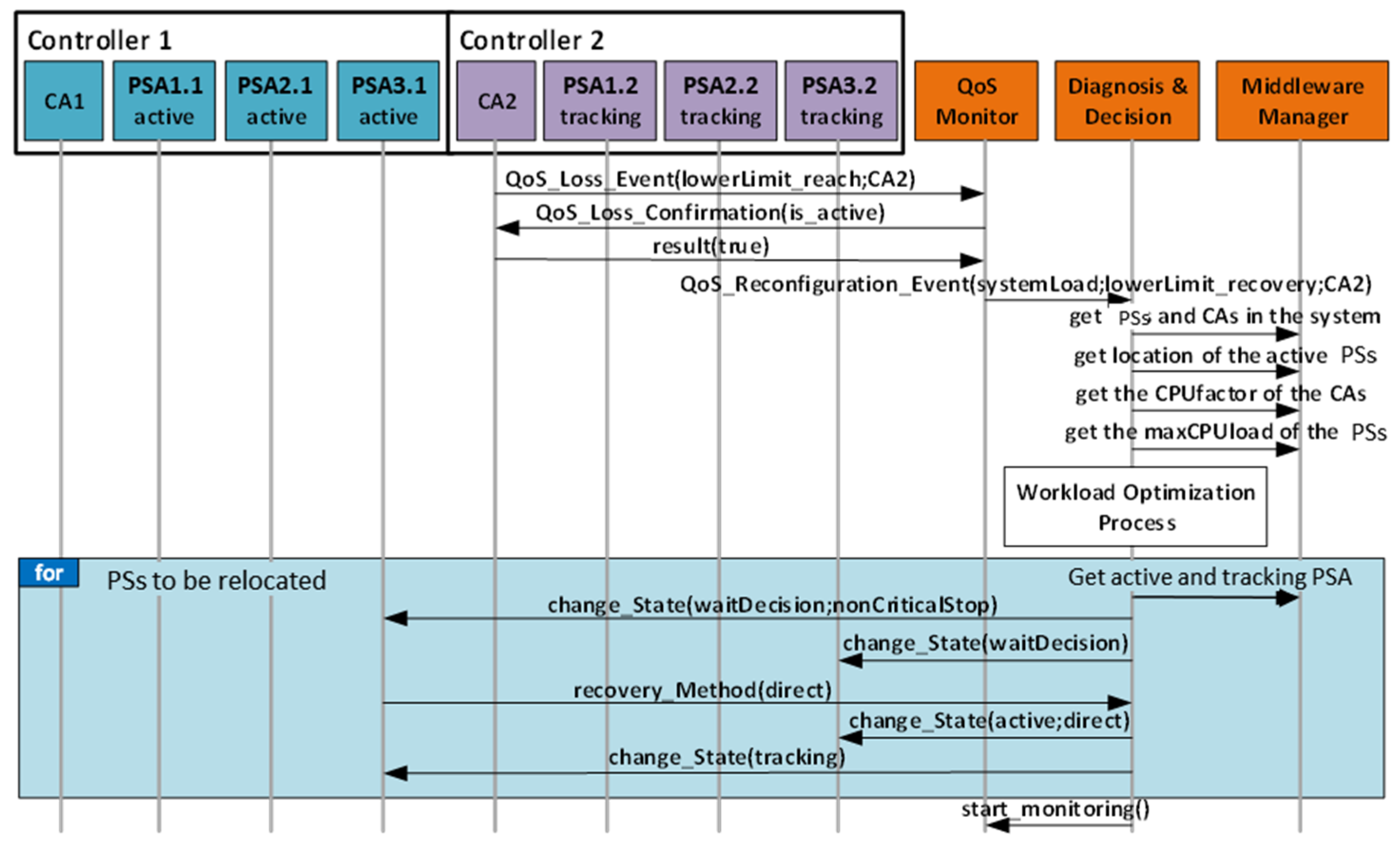
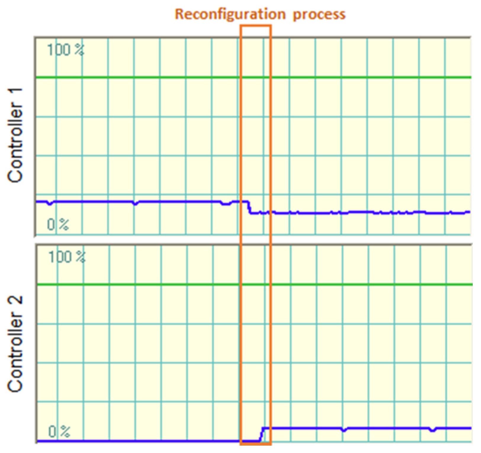
  • Step 1—QoS Loss Detection: Registration of controller 2 unbalances the system as its current workload is too low. When the workload monitoring of controller 2 detects it, the AController_AAS2 (CA2 in Figure 16) triggers an event to notify the QM (“QoS_Loss_Event(lowerLimit_reach;CA2)” in Figure 16), that eventually leads to Production System reconfiguration (“QoS_Reconfiguration_Event (systemLoad;lowerLimit_recovery;CA2)” in Figure 16).
  • Step 2—Diagnosis and Decision: The D&D receives the reconfiguration event and proceeds to initiate a negotiation among controllers to decide the new distribution. For simplicity, this negotiation process is encapsulated in the “Workload Optimization Process” block in Figure 16. The new distribution depends on the CPU factors of the AController_AASs (CA1 and CA2 in Figure 16), current distribution of the Production Services, and the CPU workload limits introduced by the Production Service software modules. When the negotiation concludes, the D&D launches the relocation of the Production Services).
  • Step 3—Reconfiguration: Relocation is represented by the “for loop: PSs to be relocated” in Figure 16, which consists of the following steps. Firstly, the D&D forces the APlant_AASs (PSAi.j in Figure 16) of the affected production service software modules to move to wait decision state (wait in Figure 13). Similarly, the D&D also forces the former active APlant_AAS to stop in the next non-critical situation of the control code (“change_State(waitDecision;nonCriticalStop)” in Figure 16). At this point, the D&D commands the execution of the production service software modules from the last known state in their new locations (“change_State(active;direct)” in Figure 16).
After the reconfiguration process, the control software of station 1 and station 2 PlantAssets are running in controller 1 and the control software of station 3 is running in controller 2. Figure 17 presents a graphic depicting the workload of the different controllers before and after the introduction of controller 2.
The scalability assessment evaluates the time the D&D takes to decide the new distribution (Step 2) and the time needed by the architecture to reconfigure the system (Step 3). This depends on the number of automation software modules to be reconfigured as well as on the number of PLCs that may run the involved software modules. For this test, all need to be relocated and the reconfiguration is launched when the control software modules operate in a non-critical state. Table 1 presents the results of this test. The first column represents the time in milliseconds the D&D takes to calculate the new distribution of the PlantAsset software module; while the following columns present the time it takes to reconfigure each.
The following figures illustrate how the execution time of the re-distribution algorithm (Figure 18) and the overall reconfiguration time (Figure 19) increase with the number of software modules to be reconfigured. However, the time to make a decision is negligible in comparison with the overall reconfiguration time, as it is computed within the D&D and it does not include negotiation. It is also remarkable that the time for reconfiguring each software module is approximately the same, around 615 ms.

5. Conclusions

This paper presents an approach aiming at adding flexibility to automation production systems following Industry 4.0 issues. It adds this flexibility by reconfiguring the control system, i.e., relocating the different functionalities over the distributed control system, assuring the execution despite controller failure.
The proposed approach defines FAPS as a set of Controller and Plant I4.0 interconnected components, which support reconfiguration according to QoS parameters. It assumes that a MAS-based middleware provides QoS management at runtime but it offers model-based support to specify flexibility needs of target systems and automatically generate: (1) the flexible automation project for each controller in the system, as well as; (2) the code of application dependent agents, being the AAS’s component manager implementation for the system’s components. Furthermore, a template for application dependent agents (controller and plant) has been defined to make FAM generic and customizable. These templates can be customized for specific processes.
The core of the framework proposed by the authors is based on MDE that allows managing complex systems. In fact, a Model Editor guides designers along the design of automation production systems, offering means for characterizing the critical situations of the production services, and collecting this information in a Model. The automatic generation has been performed via M2M and M2T transformation rules having as input the model generated by the Editor. This avoids manual programming errors, very common in these such complex situations.
The execution of the assessment has allowed to put in practice the proposed approach. As a result, several conclusions have been obtained:
  • The definition of the critical intervals in the manufacturing process, which is essential to manage flexibility properly, has proved to be a difficult task. To that end, it is necessary to rely on someone with a great knowledge of the manufacturing process, who has also taken part in the design process of the code for the controllers. As far as authors know, other approaches do not contemplate this task, as they consider that the state represents the whole process, and thus any situation should be recoverable. Nevertheless, the reality is very different.
  • The advantages of AutomationML for modeling and processing different types of data have been demonstrated. Interoperability is ensured with AutomationML as long as the integrators use PLCOpen, which is widely known and used by an increasing number of engineers and suppliers (e.g., Siemens allows to export hardware configuration to AutomationML). Despite it is a relatively new standard, it is receiving an increasing attention as exportation format for different types of data (information, code, etc.).
  • The proposed approach eases the reconfiguration and scalability of the system, allowing the reconfiguration of the control system (by adding or removing controllers) without changing the configuration of the assets. In the same way, changes in the control of the process can be easily implemented thanks to automated code generation.
However, in case the target PLC is not PLCopen compliant, the proposed approach could not be applied. That supposes a limitation in terms of scalability of the solution at design time. Regarding future work, the use of accurate simulation models as a resource to identify critical situations of the manufacturing process in a safe and controlled environment, could allow to perform cost-opportunity analyses in order to decide whether additional sensors should be included.

Author Contributions

Conceptualization, software, validation, writing—original draft preparation, U.G.; software, validation, writing—original draft preparation, A.L.; methodology, validation, writing—review and editing, A.A.; methodology, software, writing—review and editing, E.E.; conceptualization, supervision and writing—review and editing, M.M. All authors have read and agreed to the published version of the manuscript.

Funding

This work was financed by MCIU/AEI/FEDER, UE (grant number RTI2018-096116-B-I00) and by GV/EJ (grant number IT1324-19).

Institutional Review Board Statement

Not applicable.

Informed Consent Statement

Not applicable.

Data Availability Statement

The functionality of the flexible assembly cell FMS-200, located in the Department of Automatic Control and System Engineering of the University of the Basque Country is online available: https://youtu.be/7Ifp5jD3-4U (accessed on 11 January 2021). The availability of the Control System is online available: https://youtu.be/uIK1w5p3_RQ (accessed on 11 January 2021).

Acknowledgments

The authors would like to express gratitude to the Government of Spain for its support to the research project in which this work is framed (grant number RTI2018-096116-B-I00), as well as to the Government of the Basque Country Region (grant number IT1324-19). We would also like to thank to the referees which provided us their feedback for the improvement of this manuscript. A very special thank to Rafael Priego and Birgit Vogel for their collaboration in the work.

Conflicts of Interest

The authors declare no conflict of interest.

Abbreviations

The following tablecollects the acronyms and abbreviations used throughout the paper.
AASAsset Administration Shell
AMLAutomation ML
APSAutomation Production Systems
CAEXComputer Aided Engineering eXchange
CLControl Logic
D&DDiagnosis & Decision
DTDigital Twin
FAMFlexible Automation Middleware
FAPSFlexible Automation Production System
FAVAFunctional Application Design for Distributed Automation Systems
FBFunction Blocks
FSMFinite State Machine
IEInternal Element
JADEJava Agent Development Framework
MMMiddleware Manager
MDDModel Driven Design
MDEModel Driven Engineering
M2MModel to Model
M2TModel to Text
MASMulti Agent Systems
PSProduction Service
PLCsProgrammable Logic Controllers
POUProgram Organization Unit
QoSQuality of service
QMQoS Monitor
RAMI 4.0Reference Architecture Model for Industry 4.0
SysMLSystem Modeling Language
SRSystem Repository
SUCSystem Unit Classes
UMLUnified Modeling Language
XMLeXtensible Markup Language

References

  1. European Commission. Research and Innovation. Factories of the Future PPP: Towards Competitive EU Manufacturing. Available online: https://ec.europa.eu/research/press/2013/pdf/ppp/fof_factsheet.pdf (accessed on 1 February 2021).
  2. Blanchet, M.; Rinn, T.; Von Thaden, G.; de Thieulloy, G. Industry 4.0 The New Industrial Revolution How Europe Will Succeed. Available online: http://www.iberglobal.com/files/Roland_Berger_Industry.pdf (accessed on 1 February 2021).
  3. National Science and Technology Council. ADVANCED MANUFACTURING: A Snapshot of Priority Technology Areas Across the Federal Government. Available online: https://www.mrs.org/docs/default-source/advocacy-policy/resources/advanced-manufacturing—A-snapshot-of-priority-technology-areas.pdf?sfvrsn=fb15e811_6 (accessed on 1 February 2021).
  4. Liao, Y.; Deschamps, F.; Loures, E.F.R.; Ramos, L.F.P. Past, present and future of Industry 4.0—A systematic literature review and research agenda proposal. Int. J. Prod. Res. 2017, 55, 3609–3629. [Google Scholar] [CrossRef]
  5. European Commission; European Factories of the Future Research Association (EFFRA). Factories of the Future. Multi-Annual Roadmap for the Contractual PPP under Horizon 2020. Available online: https://www.effra.eu/sites/default/files/factories_of_the_future_2020_roadmap.pdf (accessed on 1 February 2021).
  6. Lindstrom, J.; Kyosti, P.; Birk, W.; Lejon, E. An initial model for zero defect manufacturing. Appl. Sci. 2020, 10, 4570. [Google Scholar] [CrossRef]
  7. Mourtzis, D. Simulation in the design and operation of manufacturing systems: State of the art and new trends. Int. J. Prod. Res. 2020, 58, 1927–1949. [Google Scholar] [CrossRef]
  8. Mourtzis, D.; Vlachou, E. A cloud-based cyber-physical system for adaptive shop-floor scheduling and condition-based maintenance. J. Manuf. Syst. 2018, 47, 179–198. [Google Scholar] [CrossRef]
  9. Lu, Y.; Xu, X.; Wang, L. Smart manufacturing process and system automation—A critical review of the standards and envisioned scenarios. J. Manuf. Syst. 2020, 56, 312–325. [Google Scholar] [CrossRef]
  10. Cotrino, A.; Sebastián, M.A.; González-Gaya, C. Industry 4.0 roadmap: Implementation for small and medium-sized enterprises. Appl. Sci. 2020, 10, 8566. [Google Scholar] [CrossRef]
  11. Tay, S.I.; Malaysia, T.H.O.; Raja, P.; Pahat, B.; Hamid, N.A.A.; Ahmad, A.N.A. An overview of industry 4.0: Definition, components, and government initiatives. J. Adv. Res. Dyn. Control. Syst. 2018, 10, 1379–1387. [Google Scholar]
  12. Florescu, A.; Barabas, S.A. Modeling and simulation of a flexible manufacturing system—A basic component of industry 4.0. Appl. Sci. 2020, 10, 8300. [Google Scholar] [CrossRef]
  13. Shen, W.; Wang, L.; Hao, Q. Agent-based distributed manufacturing process planning and scheduling: A state-of-the-art survey. IEEE Trans. Syst. Part. C 2006, 36, 563–577. [Google Scholar] [CrossRef]
  14. Krupitzer, C.; Roth, F.M.; VanSyckel, S.; Schiele, G.; Becker, C. A survey on engineering approaches for self-adaptive systems. Pervasive Mob. Comput. 2015, 17, 184–206. [Google Scholar] [CrossRef]
  15. Wang, L.; Adamson, G.; Holm, M.; Moore, P. A review of function blocks for process planning and control of manufacturing equipment. J. Manuf. Syst. 2012, 31, 269–279. [Google Scholar] [CrossRef]
  16. Nouri, H. Development of a comprehensive model and BFO algorithm for a dynamic cellular manufacturing system. Appl. Math. Model. 2016, 40, 1514–1531. [Google Scholar] [CrossRef]
  17. Urban, T.L.; Chiang, W.-C. Designing energy-efficient serial production lines: The unpaced synchronous line-balancing problem. Eur. J. Oper. Res. 2016, 248, 789–801. [Google Scholar] [CrossRef]
  18. Legat, C.; Vogel-Heuser, B. A Multi-agent architecture for compensating unforeseen failures on field control level. In Service Orientation in Holonic and Multi-Agent Manufacturing and Robotics. Studies in Computational Intelligence; Borangiu, T., Trentesaux, D., Thomas, A., Eds.; Springer: Cham, Switzerland, 2014; Volume 544, pp. 195–208. [Google Scholar] [CrossRef]
  19. Ribeiro, L.; Barata, J.; Onori, M.; Hoos, J. Industrial agents for the fast deployment of evolvable assembly systems. In Industrial Agents; Leitão, P., Karnouskos, S., Eds.; Morgan Kaufmann: Boston, MA, USA, 2015; pp. 301–322. ISBN 9780128003411. [Google Scholar] [CrossRef]
  20. Rocha, A.; Di Orio, G.; Barata, J.; Antzoulatos, N.; Castro, E.; Scrimieri, D.; Ratchev, S. An agent based framework to support plug and produce. In Proceedings of the 2014 12th IEEE International Conference on Industrial Informatics (INDIN 2014), Porto Alegre, Brazil, 27–30 July 2014; pp. 504–510. [Google Scholar] [CrossRef]
  21. Botygin, I.A.; Tartakovsky, V.A. The development and simulation research of load balancing algorithm in network infra-structures. In Proceedings of the 2014 International Conference on Mechanical Engineering, Automation and Control Systems (MEACS 2014), Tomsk, Russia, 16–18 October 2014; pp. 1–5. [Google Scholar] [CrossRef]
  22. Guo, L.; Wang, B.; Wang, W. Research of energy-efficiency algorithm based on on-demand load balancing for wireless sensor networks. In Proceedings of the 2009 International Conference on Test and Measurement, Hong Kong, China, 5–6 December 2009; pp. 22–26. [Google Scholar] [CrossRef]
  23. Merz, M.; Frank, T.; Vogel-Heuser, B. Dynamic redeployment of control software in distributed industrial automation systems during runtime. In Proceedings of the 2012 IEEE International Conference on Automation Science and Engineering (CASE 2012), Seoul, Korea, 20–24 August 2012; pp. 863–868. [Google Scholar] [CrossRef]
  24. Streit, A.; Rösch, S.; Vogel-Heuser, B. Redeployment of control software during runtime for modular automation systems taking real-time and distributed I/O into consideration. In Proceedings of the 2014 IEEE Emerging Technology and Factory Automation (ETFA 2014), Barcelona, Spain, 16–19 September 2014; pp. 1–4. [Google Scholar] [CrossRef]
  25. Salazar, L.A.C.; Mayer, F.; Schütz, D.; Vogel-Heuser, B. Platform independent multi-agent system for robust networks of production systems. IFAC PapersOnLine 2018, 51, 1261–1268. [Google Scholar] [CrossRef]
  26. Priego, R.; Iriondo, N.; Gangoiti, U.; Marcos, M. Agent Based Middleware Architecture for Reconfigurable Manufacturing Systems. Int. J. Adv. Manuf. Technol. 2017, 92, 1579–1590. [Google Scholar] [CrossRef] [Green Version]
  27. International Electrotechnical Commission. Smart Manufacturing—Reference Architecture Model Industry 4.0 (RAMI4.0). IEC Standard PAS 63088: 2017(E). Available online: https://webstore.iec.ch/publication/30082 (accessed on 3 February 2021).
  28. Wang, H. Dynamic Fault Handling and Reconfiguration for Industrial Automation Systems. Available online: https://www.ias.uni-stuttgart.de/dokumente/publikationen/2019_Dynamic_Fault_Handling_and_Reconfiguration_for_Industrial_Automation_Systems.pdf (accessed on 3 February 2021).
  29. Lyu, G.; Fazlirad, A.; Brennan, R.W. Multi-agent modeling of cyber-physical systems for IEC 61499 based distributed automation. Procedia Manuf. 2020, 51, 1200–1206. [Google Scholar] [CrossRef]
  30. Fraile, F.; Sanchis, R.; Poler, R.; Ortiz, A. Reference models for digital manufacturing platforms. Appl. Sci. 2019, 9, 4433. [Google Scholar] [CrossRef] [Green Version]
  31. Cavalieri, S.; Salafia, M.G. Insights into mapping solutions based on OPC UA information model applied to the industry 4.0 asset administration shell. Computers 2020, 9, 28. [Google Scholar] [CrossRef] [Green Version]
  32. Cavalieri, S.; Giuseppe, M.G. Asset administration shell for PLC representation based on IEC 61131-3. IEEE Access 2020, 8, 142606–142621. [Google Scholar] [CrossRef]
  33. Glossary. Available online: https://www.plattform-i40.de/SiteGlobals/PI40/Forms/Listen/Glossar/EN/Glossary_Formular.html?queryResultId=null&pageNo=0&resourceId=1081500&pageLocale=en&input_=1081494&titlePrefix=Alle (accessed on 13 February 2021).
  34. International Electrotechnical Commission. IEC 61131–3:2013 Programmable Controllers—Part 3: Programming Languages. Available online: https://webstore.iec.ch/publication/4552 (accessed on 3 February 2021).
  35. The Structure of the Administration Shell: Trilateral Perspectives from France, Italy and Germany. Available online: https://www.plattform-i40.de/PI40/Redaktion/EN/Downloads/Publikation/hm-2018-trilaterale-coop.pdf?__blob=publicationFile&v=4 (accessed on 25 February 2021).
  36. Booch, G.; Rumbaugh, J.; Jacobson, I. The Unified Modeling Language User Guide, 2nd ed.; Addison-Wesley Professional: Boston, MA, USA, 2015; ISBN 0321267974. [Google Scholar]
  37. Estevez, E.; Marcos, M.; Gangoiti, U.; Orive, D. A Tool Integration Framework for Industrial Distributed Control Systems. In Proceedings of the 44th IEEE Conference on Decision and Control, Seville, Spain, 12–15 December 2005; pp. 8373–8378. [Google Scholar] [CrossRef]
  38. Hästbacka, D.; Vepsäläinen, T.; Kuikka, S. Model-driven development of industrial process control applications. J. Syst. Softw. 2011, 84, 1100–1113. [Google Scholar] [CrossRef]
  39. Thramboulidis, K.; Frey, G. Towards a model-driven IEC 61131-based development process in industrial automation. J. Softw. Eng. Appl. 2011, 4, 217–226. [Google Scholar] [CrossRef] [Green Version]
  40. Vyatkin, V.; Hanisch, H.-M.; Pang, C.; Yang, C.-H. Closed-loop modeling in future automation system engineering and validation. IEEE Trans. Syst. Part. C 2009, 39, 17–28. [Google Scholar] [CrossRef]
  41. SysML. The SysML Specification. Available online: http://www.sysml.org (accessed on 3 February 2021).
  42. Schütz, D.; Obermeier, M.; Vogel-heuser, B. SysML-based approach for automation software development—Explorative usability evaluation of the provided notation. In Design, User Experience, and Usability. Web, Mobile, and Product Design. DUXU 2013; Lecture Notes in Computer Science; Marcus, A., Ed.; Springer: Berlin/Heidelberg, Germany, 2013; Volume 8015, pp. 568–574. [Google Scholar] [CrossRef]
  43. Fay, A.; Vogel-Heuser, B.; Frank, T.; Eckert, K.; Hadlich, T.; Diedrich, C. Enhancing a model-based engineering approach for distributed manufacturing automation systems with characteristics and design patterns. J. Syst. Softw. 2015, 101, 221–235. [Google Scholar] [CrossRef]
  44. Wehrmeister, M.A.; de Freitas, E.P.; Binotto, A.P.D.; Pereira, C.E. Combining aspects and object-orientation in model-driven engineering for distributed industrial mechatronics systems. Mechatronics 2014, 24, 844–865. [Google Scholar] [CrossRef]
  45. Marcos, M.; Estevez, E.; Perez, F.; Van der Wal, E. XML exchange of control programs. IEEE Ind. Electron. Mag. 2009, 3, 32–35. [Google Scholar] [CrossRef]
  46. Van der Wal, E. PLCopen. IEEE Ind. Electron. Mag. 2009, 3, 25. [Google Scholar] [CrossRef]
  47. Thramboulidis, K. The 3+1 SysML view-model in model integrated mechatronics. J. Softw. Eng. Appl. 2010, 3, 109–118. [Google Scholar] [CrossRef] [Green Version]
  48. Priego, R.; Armentia, A.; Estévez, E.; Marcos, M. Modeling techniques as applied to generating tool-independent automation projects. Automatisierungstechnik 2016, 64, 325–340. [Google Scholar] [CrossRef]
  49. Vogel-Heuser, B.; Schütz, D.; Frank, T.; Legat, C. Model-driven engineering of Manufacturing Automation Software Projects—A SysML-based approach. Mechatronics 2014, 24, 883–897. [Google Scholar] [CrossRef]
  50. Institute of Automation and Information Systems. Functional Application Design for Distributed Automation Systems (FAVA). Available online: https://www.ais.mw.tum.de/en/research/ (accessed on 3 February 2021).
  51. Vogel-Heuser, B.; Rösch, S. Integrated modeling of complex production automation systems to increase dependability. In Risk—A Multidisciplinary Introduction; Klüppelberg, C., Straub, D., Welpe, I., Eds.; Springer: Cham, Switzerland, 2014; pp. 363–385. [Google Scholar] [CrossRef]
  52. Cândido, G.; Colombo, A.W.; Barata, J.; Jammes, F. Service-oriented infrastructure to support the deployment of evolvable production systems. IEEE T. Ind. Inform. 2011, 7, 759–767. [Google Scholar] [CrossRef]
  53. Legat, C.; Schütz, D.; Vogel-Heuser, B. Automatic generation of field control strategies for supporting (re-)engineering of manufacturing systems. J. Intell. Manuf. 2014, 25, 1101–1111. [Google Scholar] [CrossRef]
  54. Selic, B. The pragmatics of model-driven development. IEEE Softw. 2003, 20, 19–25. [Google Scholar] [CrossRef]
  55. Binder, C.; Neureiter, C.; Lastro, G. Towards a MDA process for developing industry 4.0 applications. Int. J. Model. Opt. 2019, 9, 1–6. [Google Scholar] [CrossRef] [Green Version]
  56. Lüder, A.; Estévez, E.; Hundt, L.; Marcos, M. Automatic transformation of logic models within engineering of embedded mechatronical units. Int. J. Adv. Manuf. Technol. 2011, 54, 1077–1089. [Google Scholar] [CrossRef]
  57. AutomationML. Available online: http://www.automationml.org/ (accessed on 3 February 2021).
  58. Schmidt, D.C. Guest editor’s introduction: Model-driven engineering. Computer 2006, 39, 25–31. [Google Scholar] [CrossRef]
  59. Estévez, E.; Marcos, M. Model-based validation of industrial control systems. IEEE Trans. Ind. Inform. 2012, 8, 302–310. [Google Scholar] [CrossRef]
  60. Fedai, M.; Drath, R. CAEX—A neutral data exchange format for engineering data. ATP Int. Autom. Technol. 2005, 1, 43–51. [Google Scholar]
  61. Hergenhahn, T. LIBNODAVE—Exchange Data with Siemens PLCs. Available online: http://libnodave.sourceforge.net/ (accessed on 3 February 2021).
  62. Heiser, D.; Croes, M.; Schlameuß, R. S7netplus. Available online: https://github.com/S7NetPlus/s7netplus (accessed on 11 January 2021).
  63. Beckhoff. Automation Device Specification (ADS). Available online: https://infosys.beckhoff.com/english.php?content=../content/1033/tcadscommon/html/tcadscommon_intro.htm&id= (accessed on 3 February 2021).
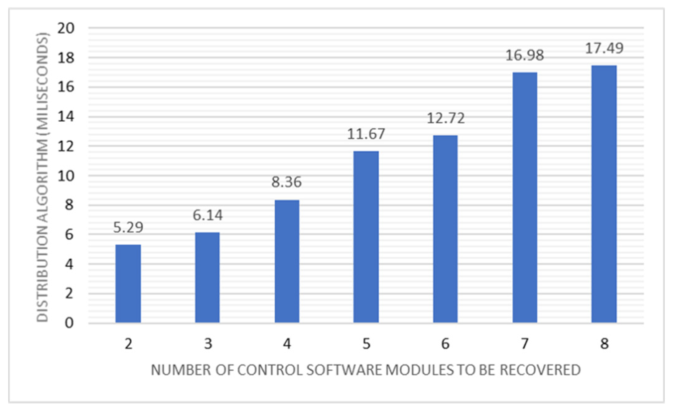
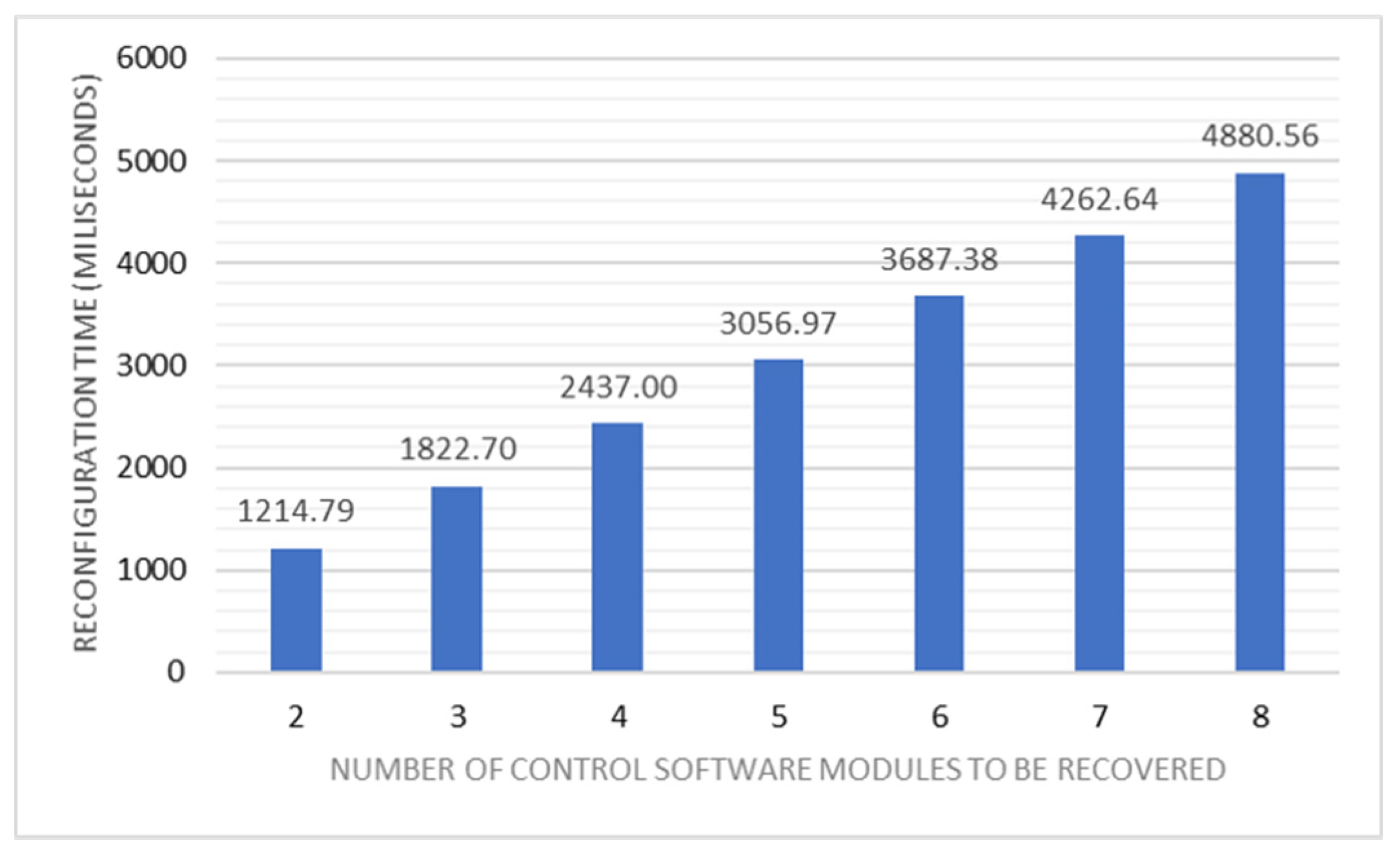
Figure 1. A Flexible Automation Production System with the following I4.0 Components: multiple Asset Administration Shell (AAS) of different assets (Controllers and Plant) are interconnected via a message exchange middleware, depicted as a message bus.
Applsci 11 02319 g001
Figure 2. Structure of a generic AAS_Controller: the figure follows the concept of an AAS from Platform Industrie 4.0 [35] to define the AAS of a controller implemented as a Markup Language. Three Sub-Models are defined, the first two related to the set of Plant Assets it can control (AAS_Plant) and the third that informs about the Plant Assets it actually controls. Every sub-model has properties that specify the actions and/or information it provides. This graphic was generated using Altova XMLSpy Version 2020.sp1.
Applsci 11 02319 g002
Figure 3. Example of ProductionService to illustrate the concept of critical situation: the figure depicts the manufacturing sequence of a crane. The steps 42 to 44 are critical situations because the state of the system is uncertain during their execution (in case of failure there is no information about the exact position of the piece). Therefore, reconfiguration cannot be performed during such steps.
Applsci 11 02319 g003
Figure 4. General Scenario of the FAM (customization of [26]): the Middleware Manager and the QoS Manager (comprising the QoS Monitor Agent and the Diagnosis & Decision Agent) constitute the core of the middleware. The former is in charge of managing the execution and maintaining the state of Controllers and Plant AAS Agents. The latter is in charge of supervising the availability of the overall control system, detecting controller faults and, if possible, recovering the Plant AASs of the failed controller.
Applsci 11 02319 g004
Figure 5. Flexible Automation Production System Meta-Model: this Meta-Model represents both, the formal expression of the software in charge of controlling a Plant Asset (on the left side) as well as the information needed in order to analyze if the control of a Plant Asset might be recoverable under a controller fault/workload balancing (on the right side). The corresponding code resides in every controller which potentially can control the Plant Asset.
Applsci 11 02319 g005
Figure 6. General Scenario of Flexible Automation Framework.
Applsci 11 02319 g006
Figure 7. CAEX libraries for Flexible Automation Systems: excerpt of a SystemUnitClassLib with AutomationML Editor. It comprises multiple System Unit Class (SUC) to define the lexicon participating in the definition of a Flexible Automation System (FAPS, AAS_Controllers, Hardware…).
Applsci 11 02319 g007
Figure 8. Flexible Automation control system design example with AutomationML Editor: (a) General Structure composed by three stations (ST1…ST3) controlled by two Controllers; (b) Characterization of the CheckPointState of the first critical situation identfied in ST1; (c) Characterization of an atomic Expression: Control_ST1.Sequence1_1.E23.Q1 = 1 AND Control_ST1.Insert_P1.E73.Q1 = 1; and (d) Characterization of an Action.
Applsci 11 02319 g008
Figure 9. General structure of a ProductionService_id program: the interface collects the parameters to configure the program. The body illustrates the skeleton of the program in ST programming language of the IEC 61131-3 standard and different sequences of actions to perform depending on the type of critical situation.
Applsci 11 02319 g009
Figure 10. Example of the execution control program generation: the upper-right part of the figure shows the interface of the program. The lower-right part of the figure shows the body of the program in ST programming language of the IEC 61131-3 standard. The statements 1 and 2 of the case structure use the designated code sections for the recoveryType of actions 1 and 2.
Applsci 11 02319 g010
Figure 11. General structure of SendStateService_id and ReceiveStateService_id programs: the interface box shows the parameters to configure the program (in this case, the number of bytes of the array). The body box presents the code of the serialization and deserialization programs in ST programming language of the IEC 61131-3 standard.
Applsci 11 02319 g011
Figure 12. Example of a Flexible Automation Project containing the POUs, data types, global variables and tasks associated to three Production Services (ST1–ST3).
Applsci 11 02319 g012
Figure 13. (a) Template of an AASPlant (AAS_PTemplate) in UML Class Diagram with detail of its methods and the states defined in its FSM and (b) Example of use of the AAS_PTemplate in Java. The characterization method of the AASPlant element allows the customization of the parameters PS_ID and recoveryInfo for different AASPlant instances.
Applsci 11 02319 g013
Figure 14. General Structure of the Diagnosis.xml file: Recovery information comprises the set of state variables to be analyzed as well as the set of critical situation masks. These masks allow to diagnose either recovery or non-recovery situations under controller failures/workloads balancing. This is performed by filtering a concrete set of state variables related to the condition to be diagnosed. This graphic was generated using Altova XMLSpy Version 2020.sp1.
Applsci 11 02319 g014
Figure 15. (a) Template of an AAS_Controller (AAS_CTemplate) in UML Class Diagram with detail of its methods and the states defined in its FSM and (b) Example of the use of the AAS_CTemplate in Java. The characterization method of the AAS_Controller element allows the customization of the parameters ID, description, IP, CPUfactor, memory and assignedPS for different AAS_Controller instances.
Applsci 11 02319 g015
Figure 16. Sequence diagram detailing the triggering of the Workload Optimization process and the redistribution of active PSs among the controllers: when Controller 2 joins the system, CA2 informs the QoS monitor that its workload is too low, and after confirmation, the QoS Monitor sends a reconfiguration event to the D&D (Step 1). The D&D requests information to the MM and after receiving it, it triggers the Workload Optimization Process (Step 2). As a result of this optimization, the D&D stops PSA3.1 at the first non-critical situation, changes the state of PSA3.1 and PSA3.2 to “wait”, and later changes the state of PSA3.2 to “active” and the state of PSA3.1 to “tracking” (Step 3).
Applsci 11 02319 g016
Figure 17. Workload of controller 1 and controller 2 before and after the reconfiguration: the orange box (reconfiguration process) corresponds to the for loop shadowed in blue in Figure 16. As a result of the reconfiguration process, the workload of Controller 1 decreases (now it has two active Production Services), and the workload of Controller 2 increases (it has one active Production Service).
Applsci 11 02319 g017
Figure 18. Distribution Algorithm Time vs. Number of control software modules.
Applsci 11 02319 g018
Figure 19. Reconfiguration Time vs. Number of control software modules.
Applsci 11 02319 g019
Table 1. Distribution algorithm and reconfiguration times.
PSAsDist.
Alg.
1st
Reconf
2nd
Reconf
3rd
Reconf
4th
Reconf
5th
Reconf
6th
Reconf
7th
Reconf
8th
Reconf
25.29610.041214.79
36.14610.661216.091822.70
48.36612.201221.511830.352437.00
511.67616.581236.591843.652450.433056.97
612.72617.411222.531827.602432.383065.813687.38
716.98625.511230.311837.612444.373050.743657.214262.64
817.49622.991242.581851.252456.503062.993667.544275.754880.56
Publisher’s Note: MDPI stays neutral with regard to jurisdictional claims in published maps and institutional affiliations.

