
A Survey of the Influence of Process Parameters on Mechanical Properties of Fused Deposition Modeling Parts


Abstract
1. Introduction
2. Process Parameters
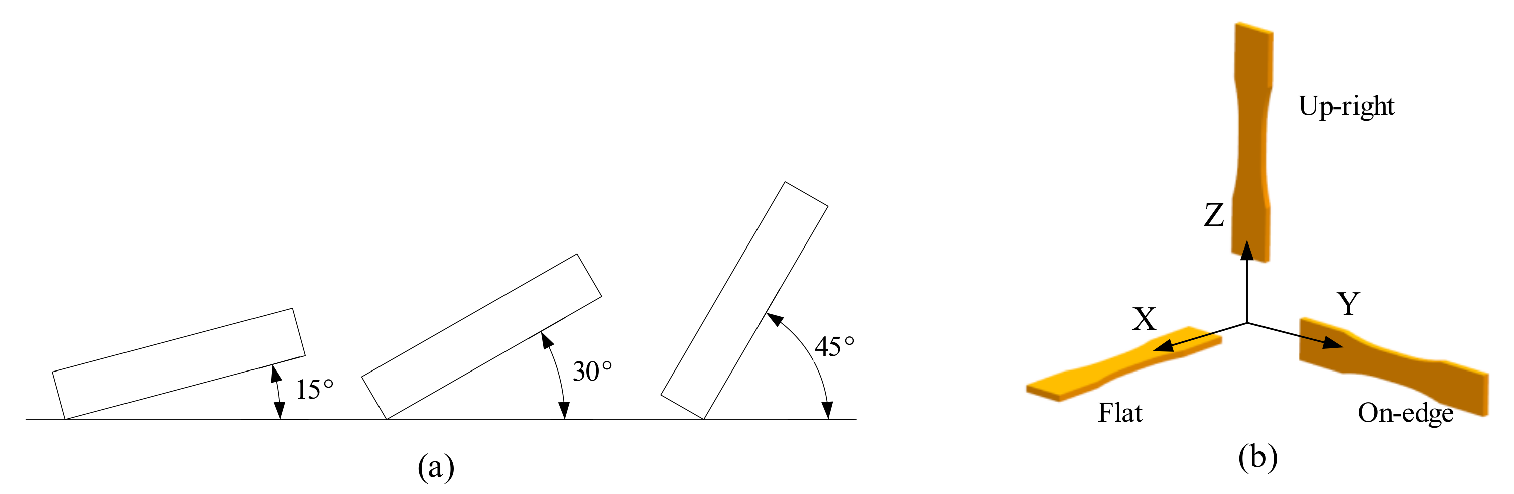
2.1. Build Orientation
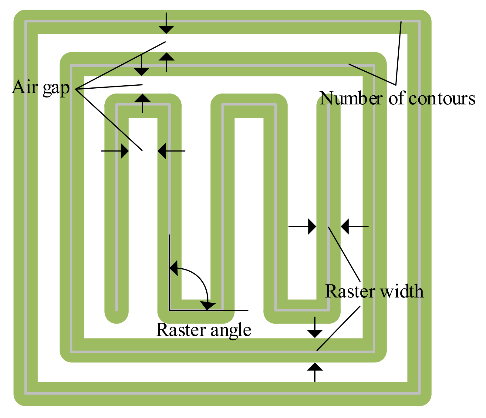
2.2. Raster Angle
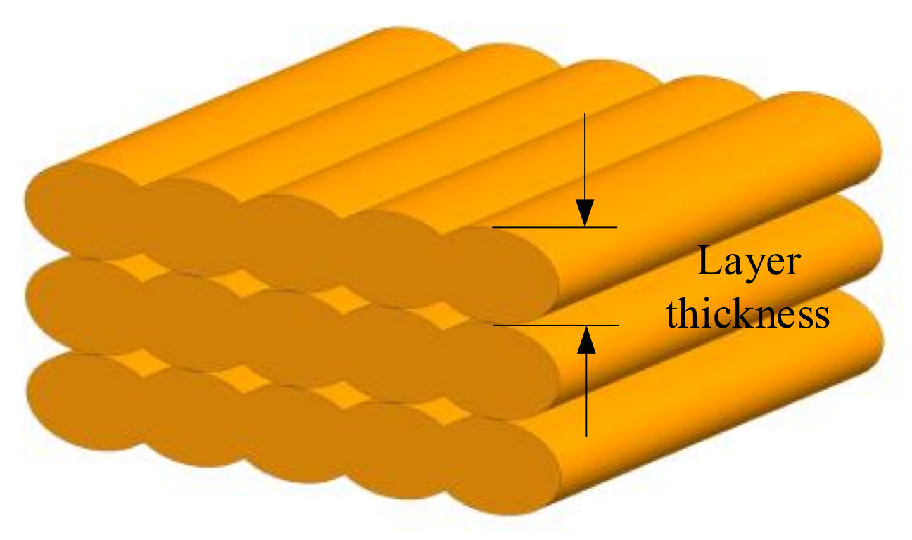
2.3. Layer Thickness
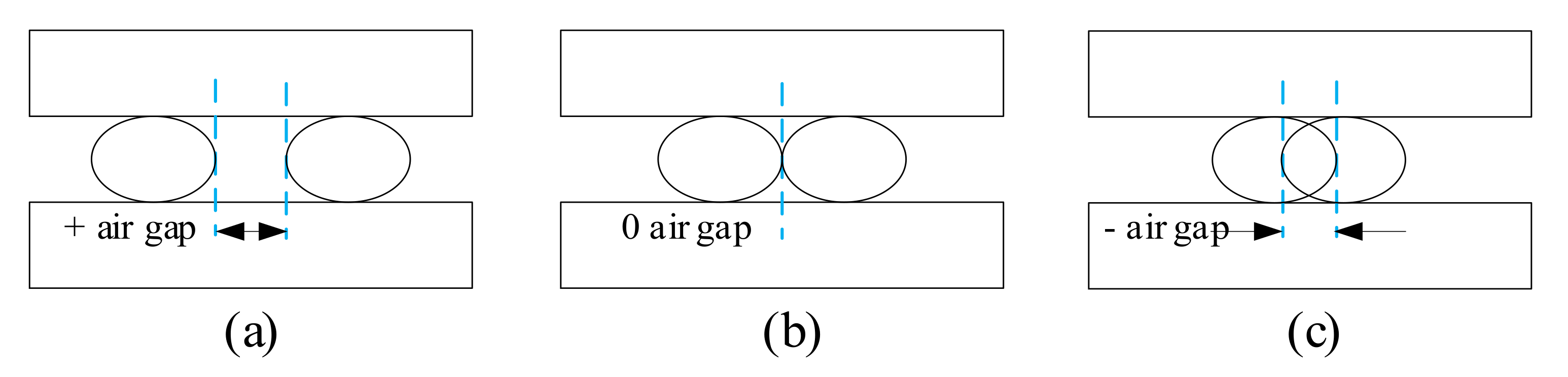
2.4. Air Gap
2.5. Raster Width
2.6. Infill Density
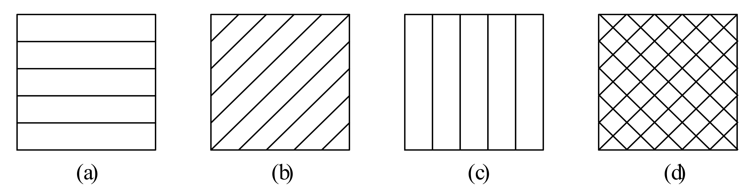
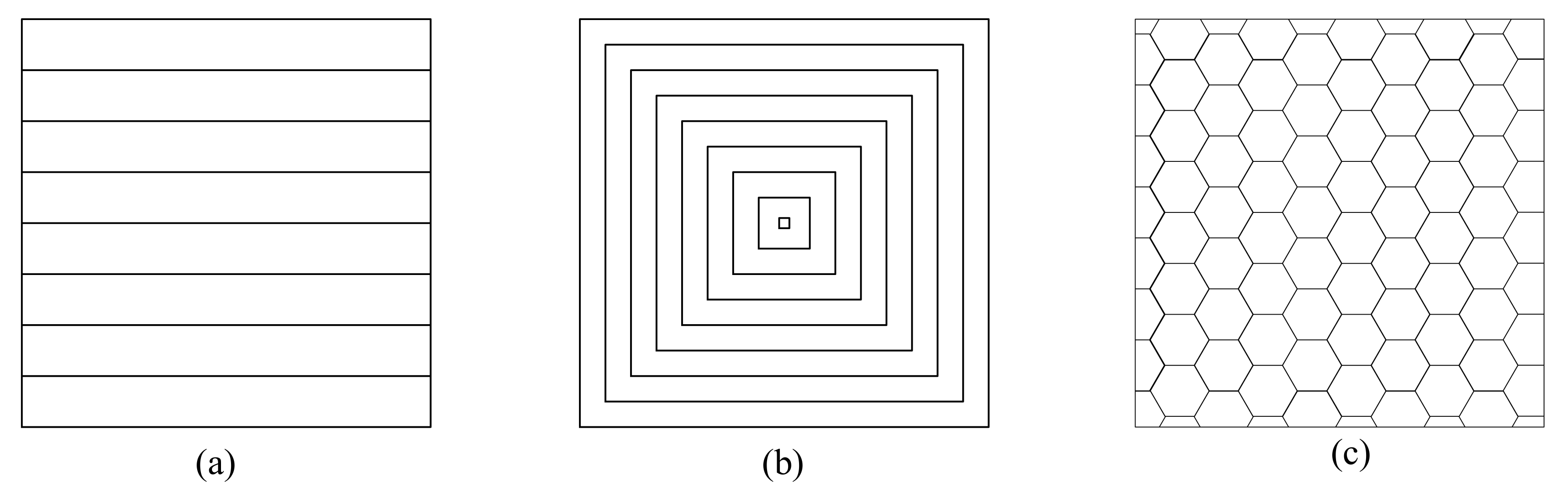
2.7. Infill Pattern
2.8. Print Speed
2.9. Number of Contours
2.10. Extrusion Temperature
3. Results and Discussions
- The work of different process parameters is coupled and combined to affect the mechanical property of FDM parts, which all have importance and effects. Generally speaking, there exists a parameter playing a dominant role. For example, extrusion temperature, layer thickness, air gap, and print speed can influence the heat transition of the structure, thus affecting the bonding between rasters and the mechanical characteristics. However, extrusion temperature is the most significant factor in determining temperature field variation, followed by layer thickness, print speed, and air gap by order of importance [102,135].
- One process parameter may affect or be affected by several other parameters, directly or indirectly. For instance, layer thickness affects the raster width and print speed. Likewise, the number of layers is related to build orientation and layer thickness in a part. What is more, infill density values significantly have an impact on the print speed, which can be changed by adjusting air gaps and raster width.
- The contribution of a single parameter may be contradictory from different aspects, which should be determined by the final effect. A typical example is raster angle. Small raster angles (e.g., 0°) will contribute to load-bearing due to filament lying along the loading direction. On the other hand, they will also lead to long rasters, which result in stress accumulation and hence weak bonding [22]. However, the final effect is that a small raster angle ensures the best tensile, compressive and flexural strength, proving that the former one plays a dominant role.
- Optimal parameter values obtained are just in theory, which should be reconsidered and adjusted in practice. According to the conclusion obtained in the former section, thinner layer thickness can help reinforce the tensile strength of the part, which, however, costs more due to more material and time usage for producing [136,137]. Consequently, a compromise needs to be made between improving property and reducing cost.
4. Research Shortcomings and Challenges
4.1. Diversity of Materials
4.2. Variety of Printers
4.3. Difference in Results
4.4. Limitation of Research Parameters
4.5. Interaction with Composites Factors
5. Summary, Recommendations, and Perspectives
5.1. Condition of Printing
5.2. Experimental Standard
5.3. Multi-Parameters Optimization
5.4. Post-Processing Technique
5.5. Facing Real Parts
5.6. Combination with 4D Printing
Author Contributions
Funding
Institutional Review Board Statement
Informed Consent Statement
Data Availability Statement
Acknowledgments
Conflicts of Interest
References
- Vyavahare, S.; Teraiya, S.; Panghal, D.; Kumar, S. Fused deposition modelling: A review. Rapid Prototyp. J. 2020, 26, 176–201. [Google Scholar] [CrossRef]
- Gordelier, T.J.; Thies, P.R.; Turner, L.; Johanning, L. Optimising the fdm additive manufacturing process to achieve maximum tensile strength: A state-of-the-art review. Rapid Prototyp. J. 2019, 25, 953–971. [Google Scholar] [CrossRef]
- Ngo, T.D.; Kashani, A.; Imbalzano, G.; Nguyen, K.T.; Hui, D. Additive manufacturing (3d printing): A review of materials, methods, applications and challenges. Compos. B Eng. 2018, 143, 172–196. [Google Scholar] [CrossRef]
- Anitha, R.; Arunachalam, S.; Radhakrishnan, P. Critical parameters influencing the quality of prototypes in fused deposition modelling. J. Mater. Process. Technol. 2001, 118, 385–388. [Google Scholar] [CrossRef]
- Horvath, D.; Noorani, R.; Mendelson, M. Improvement of surface roughness on abs 400 polymer using design of experiments (doe). Mater. Sci. Forum 2007, 561–565, 2389–2392. [Google Scholar] [CrossRef]
- Akande, S.O. Dimensional accuracy and surface finish optimization of fused deposition modelling parts using desirability function analysis. Int. J. Eng. Sci. 2015, 4, 196–202. [Google Scholar] [CrossRef]
- Wang, C.C.; Lin, T.; Hu, S. Optimizing the rapid prototyping process by integrating the taguchi method with the gray relational analysis. Rapid Prototyp. J. 2007, 13, 304–315. [Google Scholar] [CrossRef]
- Raju, M.; Gupta, M.K.; Bhanot, N.; Sharma, V.S. A hybrid pso–bfo evolutionary algorithm for optimization of fused deposition modelling process parameters. J. Intell. Manuf. 2019, 30, 2743–2758. [Google Scholar] [CrossRef]
- Baich, L.; Manogharan, G.; Marie, H. Study of infill print design on production cost-time of 3d printed abs parts. Int. J. Rapid Manuf. 2015, 5, 308–319. [Google Scholar] [CrossRef]
- Srivastava, M.; Rathee, S.; Maheshwari, S.; Kundra, T.K. Multi-objective optimisation of fused deposition modelling process parameters using rsm and fuzzy logic for build time and support material. Int. J. Rapid Manuf. 2018, 7, 25–42. [Google Scholar] [CrossRef]
- Mohamed, O.A.; Masood, S.H.; Bhowmik, J.L.; Nikzad, M.; Azadmanjiri, J. Effect of process parameters on dynamic mechanical performance of fdm pc/abs printed parts through design of experiment. J. Mater. Eng. Perform. 2016, 25, 2922–2935. [Google Scholar] [CrossRef]
- Rohde, S.; Cantrell, J.; Jerez, A.; Kroese, C.; Damiani, D.; Gurnani, R.; DiSandro, L.; Anton, J.; Young, A.; Steinbach, D.; et al. Experimental characterization of the shear properties of 3d–printed abs and polycarbonate parts. Exp. Mech. 2018, 58, 871–884. [Google Scholar] [CrossRef]
- Toro, E.V.D.; Sobrino, J.C.; Martínez, A.M.; Eguíaab, V.M. Analysis of the influence of the variables of the fused deposition modeling (fdm) process on the mechanical properties of a carbon fiber-reinforced polyamide. Procedia Manuf. 2019, 41, 731–738. [Google Scholar] [CrossRef]
- Dey, A.; Yodo, N. A systematic survey of FDM process parameter optimization and their influence on part characteristics. J. Manuf. Mater. Process. 2019, 3, 64. [Google Scholar] [CrossRef]
- Cuan-Urquizo, E.; Barocio, E.; Tejada-Ortigoza, V.; Pipes, R.; Rodriguez, C.; Roman-Flores, A. Characterization of the mechanical properties of fff structures and materials: A review on the experimental, computational and theoretical approaches. Materials 2019, 12, 895. [Google Scholar] [CrossRef]
- Sheoran, A.J.; Kumar, H. Fused deposition modeling process parameters optimization and effect on mechanical properties and part quality: Review and reflection on present research. Mater. Today Proc. 2020, 21, 1659–1672. [Google Scholar] [CrossRef]
- Mohamed, O.A.; Masood, S.H.; Bhowmik, J.L. Optimization of fused deposition modeling process parameters: A review of current research and future prospects. Adv. Manuf. 2015, 3, 42–53. [Google Scholar] [CrossRef]
- Popescu, D.; Zapciu, A.; Amza, C.; Baciu, F.; Marinescu, R. FDM process parameters influence over the mechanical properties of polymer specimens: A review. Polym. Test. 2018, 69, 157–166. [Google Scholar] [CrossRef]
- Bakır, A.A.; Atik, R.; Özerinç, S. Mechanical properties of thermoplastic parts produced by fused deposition modeling: A review. Rapid Prototyp. J. 2021, 27, 537–561. [Google Scholar] [CrossRef]
- Syrlybayev, D.; Zharylkassyn, B.; Seisekulova, A.; Akhmetov, M.; Perveen, A.; Talamona, D. Optimisation of strength properties of fdm printed parts—a critical review. Polymers 2021, 13, 1587. [Google Scholar] [CrossRef]
- Li, H.; Wang, T.; Yu, Z. The quantitative research of interaction between key parameters and the effects on mechanical property in fdm. Adv. Mater. Sci. Eng. 2017, 2017, 1–15. [Google Scholar] [CrossRef]
- Sood, A.K.; Ohdar, R.K.; Mahapatra, S.S. Parametric appraisal of mechanical property of fused deposition modelling processed parts. Mater. Des. 2010, 31, 287–295. [Google Scholar] [CrossRef]
- Durgun, I.; Ertan, R. Experimental investigation of fdm process for improvement of mechanical properties and production cost. Rapid Prototyp. J. 2014, 20, 228–235. [Google Scholar] [CrossRef]
- Rodriguez, J.F.; Thomas, J.P.; Renaud, J.E. Design of fused-deposition abs components for stiffness and strength. J. Mech. Des. 2003, 125, 545–551. [Google Scholar] [CrossRef]
- Ashtankar, K.M.; Kuthe, A.M.; Rathour, B.S. Effect of build orientation on mechanical properties of rapid prototyping (fused deposition modelling) made acrylonitrile butadiene styrene (abs) parts. In Proceedings of the ASME 2013 International Mechanical Engineering Congress and Exposition, San Diego, CA, USA, 15–21 November 2013. [Google Scholar] [CrossRef]
- Panda, S.K.; Padhee, S.; Anoop Kumar, S.; Mahapatra, S.S. Optimization of fused deposition modelling (fdm) process parameters using bacterial foraging technique. Intell. Inf. Manag. 2009, 1, 89–97. [Google Scholar] [CrossRef]
- Chacón, J.; Caminero, M.; García-Plaza, E.; Núñez, P. Additive manufacturing of pla structures using fused deposition modelling: Effect of process parameters on mechanical properties and their optimal selection. Mater. Des. 2017, 124, 143–157. [Google Scholar] [CrossRef]
- Alafaghani, A.; Qattawi, A.; Alrawi, B.; Guzman, A. Experimental optimization of fused deposition modelling processing parameters: A design-for-manufacturing approach. Procedia Manuf. 2017, 10, 791–803. [Google Scholar] [CrossRef]
- Lee, C.S.; Kim, S.G.; Kim, H.J.; Ahn, S.H. Measurement of anisotropic compressive strength of rapid prototyping parts. J. Mater. Process. Technol. 2002, 187–188, 248–257. [Google Scholar] [CrossRef]
- Górski, F.; Wichniarek, R.; Kuczko, W.; Andrzejewski, J. Experimental determination of critical orientation of abs parts manufactured using fused deposition modelling technology. J. Mach. Eng. 2015, 15, 121–132. [Google Scholar]
- Hernandez, R.; Slaughter, D.; Whaley, D.; Tate, J.; Asiabanpour, B. Analyzing the tensile, compressive, and flexural properties of 3d printed abs p430 plastic based on printing orientation using fused deposition modeling. In Proceedings of the 27th Annual International Solid Freeform Fabrication Symposium, Austin, TX, USA, 12–14 August 2019. [Google Scholar]
- Bertoldi, M.; Yardimci, M.A.; Pistor, C.M.; Guceri, S.I.; Sala, G. Mechanical characterization of parts processed via fused deposition. In Proceedings of the 9th Solid Freeform Fabrication Symposium, Austin, TX, USA, 11–13 August 1998. [Google Scholar]
- Zou, R.; Xia, Y.; Liu, S.; Hu, P.; Hou, W.; Hu, Q.; Shan, C. Isotropic and anisotropic elasticity and yielding of 3d printed material. Compos. B. Eng. 2016, 99, 506–513. [Google Scholar] [CrossRef]
- Raney, K.; Lani, E.; Kalla, D.K. Experimental characterization of the tensile strength of abs parts manufactured by fused deposition modeling process. Mater. Today Proc. 2017, 4, 7956–7961. [Google Scholar] [CrossRef]
- Domingo-Espin, M.; Puigoriol-Forcada, J.M.; Garcia-Granada, A.-A.; Llumà, J.; Borros, S.; Reyes, G. Mechanical property characterization and simulation of fused deposition modeling polycarbonate parts. Mater. Des. 2015, 83, 670–677. [Google Scholar] [CrossRef]
- Smith, W.C.; Dean, R.W. Structural characteristics of fused deposition modeling polycarbonate material. Polym. Test. 2013, 32, 1306–1312. [Google Scholar] [CrossRef]
- Zaldivar, R.; Witkin, D.; McLouth, T.; Patel, D.; Schmitt, K.; Nokes, J. Influence of processing and orientation print effects on the mechanical and thermal behavior of 3d-printed ultem® 9085 material. Addit. Manuf. 2017, 13, 71–80. [Google Scholar] [CrossRef]
- Taylor, G.; Wang, X.; Mason, L.; Leu, M.C.; Chandrashekhara, K.; Schniepp, T.; Jones, R. Flexural behavior of additively manufactured ultem 1010: Experiment and simulation. Rapid Prototyp. J. 2018, 24, 1003–1011. [Google Scholar] [CrossRef]
- Uddin, M.; Sidek, M.; Faizal, M.; Ghomashchi, R.; Pramanik, A. Evaluating mechanical properties and failure mechanisms of fused deposition modeling acrylonitrile butadiene styrene parts. J. Manuf. Sci. Eng. 2017, 139, 081018. [Google Scholar] [CrossRef]
- Es-Said, O.; Foyos, J.; Noorani, R.; Mendelson, M.; Marloth, R.; Pregger, B. Effect of layer orientation on mechanical properties of rapid prototyped samples. Mater. Manuf. Process. 2000, 15, 107–122. [Google Scholar] [CrossRef]
- Rodríguez-Panes, A.; Claver, J.; Camacho, A. The influence of manufacturing parameters on the mechanical behaviour of pla and abs pieces manufactured by fdm: A comparative analysis. Materials 2018, 11, 1333. [Google Scholar] [CrossRef]
- Somireddy, M.; De Moraes, D.A.; Czekanski, A. Flexural behavior of fdm parts: Experimental, analytical and numerical study. In Proceedings of the 28th Annual International Solid Freeform Fabrication Symposium, Austin, TX, USA, 7–9 August 2017. [Google Scholar]
- Vaezi, M.; Chua, C.K. Effects of layer thickness and binder saturation level parameters on 3d printing process. J. Adv. Manuf. Technol. 2011, 53, 275–284. [Google Scholar] [CrossRef]
- Ahn, S.H.; Montero, M.; Odell, D.; Roundy, S.; Wright, P.K. Anisotropic material properties of fused deposition modeling abs. Rapid Prototyp. J. 2002, 8, 248–257. [Google Scholar] [CrossRef]
- Magalhães, L.C.; Volpato, N.; Luersen, M.A. Evaluation of stiffness and strength in fused deposition sandwich specimens. J. Braz. Soc. Mech. Sci. 2014, 36, 449–459. [Google Scholar] [CrossRef]
- Ziemian, S.; Okwara, M.; Ziemian, C.W. Tensile and fatigue behavior of layered acrylonitrile butadiene styrene. Rapid Prototyp. J. 2015, 21, 270–278. [Google Scholar] [CrossRef]
- Zhou, Y.G.; Su, B.; Turng, L.S. Deposition-induced effects of isotactic polypropylene and polycarbonate composites during fused deposition modeling. Rapid Prototyp. J. 2017, 23, 189. [Google Scholar] [CrossRef]
- Garg, A.; Bhattacharya, A.; Batish, A. Failure investigation of fused deposition modelling parts fabricated at different raster angles under tensile and flexural loading. Proc. Inst. Mech. Eng. Part B J. Eng. Manuf. 2017, 231, 2031–2039. [Google Scholar] [CrossRef]
- Ziemian, C.; Sharma, M.; Ziemian, S. Anisotropic mechanical properties of abs parts fabricated by fused deposition modelling. In Mechanical Engineering; Gokcek, M., Ed.; IntechOpen: London, UK, 2012; pp. 159–180. [Google Scholar] [CrossRef]
- Fatimatuzahraa, A.W.; Farahaina, B.; Yusoff, W. The effect of employing different raster orientations on the mechanical properties and microstructure of fused deposition modeling parts. In Proceedings of the 2011 IEEE Symposium on Business, Engineering and Industrial Applications, Langkawi, Malaysia, 25–28 September 2011. [Google Scholar] [CrossRef]
- Jap, N.S.F.; Pearce, G.M.; Hellier, A.K.; Russell, N.; Parr, W.C.; Walsh, W.R. The effect of raster orientation on the static and fatigue properties of filament deposited abs polymer. Int. J. Fatigue 2019, 124, 328–337. [Google Scholar] [CrossRef]
- Diaconescu, C.; Tabacu, S.; Oltean, A. Design and analysis of a fused deposition modelling manufactured part. In Proceedings of the CAR2017 International Congress of Automotive and Transport Engineering—Mobility Engineering and Environment, Pitesti, Romania, 8–10 November 2017. [Google Scholar] [CrossRef]
- Hart, K.R.; Wetzel, E.D. Fracture behavior of additively manufactured acrylonitrile butadiene styrene (abs) materials. Eng. Fract. Mech. 2017, 177, 1–13. [Google Scholar] [CrossRef]
- Arbeiter, F.; Spoerk, M.; Wiener, J.; Gosch, A.; Pinter, G. Fracture mechanical characterization and lifetime estimation of near-homogeneous components produced by fused filament fabrication. Polym. Test. 2018, 66, 105–113. [Google Scholar] [CrossRef]
- Bellini, A.; Güçeri, S. Mechanical characterization of parts fabricated using fused deposition modeling. Rapid Prototyp. J. 2003, 9, 252–264. [Google Scholar] [CrossRef]
- Balderrama-Armendariz, C.O.; MacDonald, E.; Espalin, D.; Cortes-Saenz, D.; Wicker, R.; Maldonado-Macias, A. Torsion analysis of the anisotropic behavior of fdm technology. Int. J. Adv. Manuf. Technol. 2018, 96, 307–317. [Google Scholar] [CrossRef]
- Cantrell, J.T.; Rohde, S.; Damiani, D.; Gurnani, R.; DiSandro, L.; Anton, J.; Young, A.; Jerez, A.; Steinbach, D.; Kroese, C. Experimental characterization of the mechanical properties of 3d printed abs and polycarbonate parts. Rapid Prototyp. J. 2016, 23, 811–824. [Google Scholar] [CrossRef]
- Torrado, A.R.; Roberson, D.A. Failure analysis and anisotropy evaluation of 3d-printed tensile test specimens of different geometries and print raster patterns. J. Fail. Anal. Prev. 2016, 16, 154–164. [Google Scholar] [CrossRef]
- Letcher, T.; Rankouhi, B.; Javadpour, S. Experimental study of mechanical properties of additively manufactured abs plastic as a function of layer parameters. In Proceedings of the ASME 2015 International Mechanical Engineering Congress and Exposition (IMECE), Houston, TX, USA, 13–19 November 2015. [Google Scholar] [CrossRef]
- Casavola, C.; Cazzato, A.; Moramarco, V.; Pappalettere, C. Orthotropic mechanical properties of fused deposition modelling parts described by classical laminate theory. Mater. Des. 2016, 90, 453–458. [Google Scholar] [CrossRef]
- Lanzotti, A.; Grasso, M.; Staiano, G.; Martorelli, M. The impact of process parameters on mechanical properties of parts fabricated in pla with an open-source 3-d printer. Rapid Prototyp. J. 2015, 21, 604–617. [Google Scholar] [CrossRef]
- Rankouhi, B.; Javadpour, S.; Delfanian, F.; Letcher, T. Failure analysis and mechanical characterization of 3d printed abs with respect to layer thickness and orientation. J. Fail. Anal. Prev. 2016, 16, 467–481. [Google Scholar] [CrossRef]
- Tymrak, B.; Kreiger, M.; Pearce, J.M. Mechanical properties of components fabricated with open-source 3-d printers under realistic environmental conditions. Mater. Des. 2014, 58, 242–246. [Google Scholar] [CrossRef]
- Rajpurohit, S.R.; Dave, H.K. Analysis of tensile strength of a fused filament fabricated pla part using an open-source 3d printer. Int. J. Adv. Manuf. Technol. 2019, 101, 1525–1536. [Google Scholar] [CrossRef]
- Wu, W.; Geng, P.; Li, G.; Zhao, D.; Zhang, H.; Zhao, J. Influence of layer thickness and raster angle on the mechanical properties of 3d-printed peek and a comparative mechanical study between peek and abs. Materials 2015, 8, 5834–5846. [Google Scholar] [CrossRef]
- Garg, A.; Bhattacharya, A. An insight to the failure of fdm parts under tensile loading: Finite element analysis and experimental study. Int. J. Mech. Sci. 2017, 120, 225–236. [Google Scholar] [CrossRef]
- Nidagundi, V.B.; Keshavamurthy, R.; Prakash, C.P.S. Studies on parametric optimization for fused deposition modelling process. Mater. Today Proc. 2015, 2, 1691–1699. [Google Scholar] [CrossRef]
- Carneiro, O.S.; Silva, A.F.; Gomes, R. Fused deposition modeling with polypropylene. Mater. Des. 2015, 83, 768–776. [Google Scholar] [CrossRef]
- Dong, Y.; Milentis, J.; Pramanik, A. Additive manufacturing of mechanical testing samples based on virgin poly (lactic acid)(pla) and pla/wood fibre composites. Adv. Manuf. 2018, 6, 71–82. [Google Scholar] [CrossRef]
- D’Amico, A.A.; Debaie, A.; Peterson, A.M. Effect of layer thickness on irreversible thermal expansion and interlayer strength in fused deposition modeling. Rapid Prototyp. J. 2017, 23, 943–953. [Google Scholar] [CrossRef]
- Rodríguez, J.F.; Thomas, J.P.; Renaud, J.E. Mechanical behavior of acrylonitrile butadiene styrene (abs) fused deposition materials: Experimental investigation. Rapid Prototyp. J. 2001, 7, 148–158. [Google Scholar] [CrossRef]
- Too, M.H.; Leong, K.F.; Chua, C.K.; Du, Z.H.; Yang, S.F.; Cheah, C.M.; Ho, S.L. Investigation of 3d non-random porous structures by fused deposition modelling. Int. J. Adv. Manuf. Technol. 2002, 19, 217–223. [Google Scholar] [CrossRef]
- Dawoud, M.; Taha, I.; Ebeid, S.J. Mechanical behaviour of abs: An experimental study using fdm and injection moulding techniques. J. Manuf. Process. 2016, 21, 39–45. [Google Scholar] [CrossRef]
- Masood, S.H.; Mau, K.; Song, W.Q. Tensile properties of processed fdm polycarbonate material. Mater. Sci. Forum. 2010, 654, 2556–2559. [Google Scholar] [CrossRef]
- Slonov, A.L.; Khashirov, A.A.; Zhansitov, A.A.; Rzhevskaya, E.V.; Khashirova, S.Y. The influence of the 3d-printing technology on the physical and mechanical properties of polyphenylene sulfone. Rapid Prototyp. J. 2018, 24, 1124–1130. [Google Scholar] [CrossRef]
- Hossain, M.S.; Ramos, J.; Espalin, D.; Perez, M.; Wicker, R. Improving tensile mechanical properties of fdm-manufactured specimens via modifying build parameters. In Proceedings of the 2013 International Solid Freeform Fabrication Symposium: An Additive Manufacturing Conference, Austin, TX, USA, 12–14 August 2013. [Google Scholar] [CrossRef]
- Hossain, M.S.; Espalin, D.; Ramos, J.; Perez, M.; Wicker, R. Improved mechanical properties of fused deposition modeling-manufactured parts through build parameter modifications. J. Manuf. Sci. Eng. 2014, 136, 061002. [Google Scholar] [CrossRef]
- Montero, M.; Roundy, S.; Odell, D.; Ahn, S.-H.; Wright, P.K. Material characterization of fused deposition modeling (fdm) abs by designed experiments. Soc. Manuf. Eng. 2001, 10, 1–21. [Google Scholar]
- Bagsik, A.; Schöppner, V.; Klemp, E. Fdm part quality manufactured with ultem* 9085. In Proceedings of the 14th International Scientific Conference on Polymeric Materials, Halle, Germany, 15–17 September 2010. [Google Scholar]
- Gebisa, A.W.; Lemu, H.G. Investigating effects of fused-deposition modeling (fdm) processing parameters on flexural properties of ultem 9085 using designed experiment. Materials 2018, 11, 500. [Google Scholar] [CrossRef]
- Gebisa, A.W.; Lemu, H.G. Influence of 3d printing fdm process parameters on tensile property of ultem 9085. Procedia Manuf. 2019, 30, 331–338. [Google Scholar] [CrossRef]
- Deng, X.; Zeng, Z.; Peng, B.; Yan, S.; Ke, W. Mechanical properties optimization of poly-ether-ether-ketone via fused deposition modeling. Materials 2018, 11, 216. [Google Scholar] [CrossRef] [PubMed]
- Ang, K.C.; Leong, K.F.; Chua, C.K.; Chandrasekaran, M. Investigation of the mechanical properties and porosity relationships in fused deposition modelling-fabricated porous structures. Rapid Prototyp. J. 2006, 12, 100–105. [Google Scholar] [CrossRef]
- Rayegani, F.; Onwubolu, G.C. Fused deposition modelling (fdm) process parameter prediction and optimization using group method for data handling (gmdh) and differential evolution (de). Int. J. Adv. Manuf. Technol. 2014, 73, 509–519. [Google Scholar] [CrossRef]
- Onwubolu, G.C.; Rayegani, F. Characterization and optimization of mechanical properties of abs parts manufactured by the fused deposition modelling process. Int. J. Manuf. Eng. 2014, 2014, 598531. [Google Scholar] [CrossRef]
- Liu, X.; Zhang, M.; Li, S.; Si, L.; Peng, J.; Hu, Y. Mechanical property parametric appraisal of fused deposition modeling parts based on the gray taguchi method. Int. J. Adv. Manuf. Technol. 2017, 89, 2387–2397. [Google Scholar] [CrossRef]
- Gkartzou, E.; Koumoulos, E.P.; Charitidis, C.A. Production and 3d printing processing of bio-based thermoplastic filament. Manuf. Rev. 2017, 4, 1. [Google Scholar] [CrossRef]
- Elkholy, A.; Kempers, R. Investigation into the influence of fused deposition modeling (fdm) process parameters on the thermal properties of 3d-printed parts. In Proceedings of the 2018 Canadian Society for Mechanical Engineering (CSME) International Congress, Toronto, ON, Canada, 27–30 May 2018. [Google Scholar] [CrossRef]
- Rajpurohit, S.R.; Dave, H.K. Flexural strength of fused filament fabricated (fff) pla parts on an open-source 3d printer. Adv. Manuf. 2018, 6, 430–441. [Google Scholar] [CrossRef]
- Alvarez, K.L.; Lagos, R.F.; Aizpun, M. Investigating the influence of infill percentage on the mechanical properties of fused deposition modelled abs parts. Ing. Investig. 2016, 36, 110–116. [Google Scholar] [CrossRef]
- Martikka, O.; Kärki, T.; Wu, Q.L. Mechanical properties of 3d-printed wood-plastic composites. In Key Engineering Materials; Trans Tech. Publ. Ltd.: Freienbach, Switzerland, 2018; Volume 777, pp. 499–507. [Google Scholar] [CrossRef]
- Gomez-Gras, G.; Jerez-Mesa, R.; Travieso-Rodriguez, J.A.; Lluma-Fuentes, J. Fatigue performance of fused filament fabrication PLA specimens. Mater. Des. 2018, 140, 278–285. [Google Scholar] [CrossRef]
- Aw, Y.Y.; Yeoh, C.K.; Idris, M.A.; Teh, P.L.; Hamzah, K.A.; Sazali, S.A. Effect of printing parameters on tensile, dynamic mechanical, and thermoelectric properties of fdm 3d printed cabs/zno composites. Materials 2018, 11, 466. [Google Scholar] [CrossRef] [PubMed]
- Kerekes, T.W.; Lim, H.; Joe, W.Y.; Yun, G.J. Characterization of process–deformation/damage property relationship of fused deposition modeling (fdm) 3d-printed specimens. Addit. Manuf. 2019, 25, 532–544. [Google Scholar] [CrossRef]
- Lužanin, O.; Movrin, D.; Plančak, M. Effect of layer thickness, deposition angle, and infill on maximum flexural force in fdm-built specimens. Int. J. Plast. 2014, 39, 49–58. [Google Scholar]
- Cho, E.E.; Hein, H.H.; Lynn, Z.; Hla, S.J.; Tran, T. Investigation on influence of infill pattern and layer thickness on mechanical strength of pla material in 3d printing technology. J. Eng. Sci. Res. 2019, 3, 27–37. [Google Scholar] [CrossRef]
- Dave, H.K.; Patadiya, N.H.; Prajapati, A.R.; Rajpurohit, S.R. Effect of infill pattern and infill density at varying part orientation on tensile properties of fused deposition modeling-printed poly-lactic acid part. Proc. Inst. Mech. Eng. Part C J. Mech. Eng. Sci. 2021, 235, 1811–1827. [Google Scholar] [CrossRef]
- Fernandez-Vicente, M.; Calle, W.; Ferrandiz, S.; Conejero, A. Effect of infill parameters on tensile mechanical behavior in desktop 3d printing. 3D Print. Addit. Manuf. 2016, 3, 183–192. [Google Scholar] [CrossRef]
- Akhoundi, B.; Behravesh, A.H. Effect of filling pattern on the tensile and flexural mechanical properties of fdm 3d printed products. Exp. Mech. 2019, 59, 883–897. [Google Scholar] [CrossRef]
- Nagendra, J.; Prasad, M.S. FDM process parameter optimization by taguchi technique for augmenting the mechanical properties of nylon–aramid composite used as filament material. J. Inst. Eng. (India) Ser. C 2020, 101, 313–322. [Google Scholar] [CrossRef]
- Ning, F.; Cong, W.; Qiu, J.; Wei, J.; Wang, S. Additive manufacturing of carbon fiber reinforced thermoplastic composites using fused deposition modeling. Compos. Part B Eng. 2015, 80, 369–378. [Google Scholar] [CrossRef]
- Li, H.; Wang, T.; Sun, J.; Yu, Z. The effect of process parameters in fused deposition modelling on bonding degree and mechanical properties. Rapid Prototyp. J. 2018, 24, 80–92. [Google Scholar] [CrossRef]
- Christiyan, K.J.; Chandrasekhar, U.; Venkateswarlu, K. A study on the influence of process parameters on the mechanical properties of 3d printed abs composite. IOP Conf. Ser. Mater. Sci. Eng. 2016, 114, 012109. [Google Scholar] [CrossRef]
- Santana, L.; Ahrens, C.H.; Netto, A.C.S.; Bonin, C. Evaluating the deposition quality of parts produced by an open-source 3d printer. Rapid Prototyp. J. 2017, 23, 796–803. [Google Scholar] [CrossRef]
- Kačergis, L.; Mitkus, R.; Sinapius, M. Influence of fused deposition modeling process parameters on the transformation of 4d printed morphing structures. Smart Mater. Struct. 2019, 28, 105042. [Google Scholar] [CrossRef]
- Lužanin, O.; Guduric, V.; Ristic, I.; Muhic, S. Investigating impact of five build parameters on the maximum flexural force in fdm specimens–a definitive screening design approach. Rapid Prototyp. J. 2017, 23, 1088–1098. [Google Scholar] [CrossRef]
- Faes, M.; Ferraris, E.; Moens, D. Influence of inter-layer cooling time on the quasi-static properties of abs components produced via fused deposition modelling. Procedia Cirp. 2016, 42, 748–753. [Google Scholar] [CrossRef]
- Zhang, Y.; Chou, K. A parametric study of part distortions in fused deposition modelling using three-dimensional finite element analysis. Proc. Inst. Mech. Eng. Part B J. Eng. Manuf. 2008, 222, 959–968. [Google Scholar] [CrossRef]
- Kung, C.; Kuan, H.C.; Kuan, C.F. Evaluation of tensile strength of 3d printed objects with fdm process on reprap platform. In Proceedings of the 2018 1st IEEE International Conference on Knowledge Innovation and Invention (ICKII), Jeju, Korea, 23–27 July 2018. [Google Scholar] [CrossRef]
- Mahmood, S.; Qureshi, A.J.; Goh, K.L.; Talamona, D. Tensile strength of partially filled fff printed parts: Experimental results. Rapid Prototyp. J. 2017, 23, 122–128. [Google Scholar] [CrossRef]
- Croccolo, D.; De Agostinis, M.; Olmi, G. Experimental characterization and analytical modelling of the mechanical behaviour of fused deposition processed parts made of abs-m30. Comput. Mater. Sci. 2013, 79, 506–518. [Google Scholar] [CrossRef]
- Griffiths, C.A.; Howarth, J.; Rowbotham, G.D.A.; Rees, A. Effect of build parameters on processing efficiency and material performance in fused deposition modelling. Procedia CIRP 2016, 49, 28–32. [Google Scholar] [CrossRef]
- Aliheidari, N.; Tripuraneni, R.; Ameli, A.; Nadimpalli, S. Fracture resistance measurement of fused deposition modeling 3d printed polymers. Polym. Test. 2017, 60, 94–101. [Google Scholar] [CrossRef]
- Rinanto, A.; Nugroho, A.; Prasetyo, H.; Pujiyanto, E. Simultaneous optimization of tensile strength, energy consumption and processing time on fdm process using taguchi and pcr-topsis. In Proceedings of the 4th International Conference on Science and Technology (ICST), Yogyakarta, Indonesia, 7–8 August 2018. [Google Scholar] [CrossRef]
- Sun, Q.; Rizvi, G.; Bellehumeur, C.; Gu, P. Effect of processing conditions on the bonding quality of fdm polymer filaments. Rapid Prototyp. J. 2008, 14, 72–80. [Google Scholar] [CrossRef]
- Leite, M.; Fernandes, J.; Deus, A.M.; Reis, L.; Vaz, M.F. Study of the influence of 3d printing parameters on the mechanical properties of pla. In Proceedings of the 3rd International Conference on Progress in Additive Manufacturing (Pro-AM 2018), Nanyang Executive Centre, Singapore, 14–17 May 2018. [Google Scholar] [CrossRef]
- Sun, X.; Cao, L.; Ma, H.; Peng, G.; Zhanwei, B.; Cheng, L. Experimental analysis of high temperature peek materials on 3d printing test. In Proceedings of the 9th International Conference on Measuring Technology and Mechatronics Automation (ICMTMA), Changsha, China, 14–15 January 2017. [Google Scholar] [CrossRef]
- Yang, T.C. Effect of extrusion temperature on the physico-mechanical properties of unidirectional wood fiber-reinforced polylactic acid composite (wfrpc) components using fused deposition modeling. Polymers 2018, 10, 976. [Google Scholar] [CrossRef] [PubMed]
- Upadhyay, K.; Dwivedi, R.; Singh, A.K. Determination and comparison of the anisotropic strengths of fused deposition modeling p400 abs. In Advances in 3D Printing & Additive Manufacturing Technologies; Wimpenny, D.I., Pandey, P.M., Kumar, L.J., Eds.; Springer: Singapore, 2017; pp. 9–28. [Google Scholar] [CrossRef]
- Kamaal, M.; Anas, M.; Rastogi, H.; Bhardwaj, N.; Rahaman, A. Effect of fdm process parameters on mechanical properties of 3d-printed carbon fibre–pla composite. Prog Addit Manuf. 2021, 6, 63–69. [Google Scholar] [CrossRef]
- Tanikella, N.G.; Wittbrodt, B.; Pearce, J.M. Tensile strength of commercial polymer materials for fused filament fabrication 3d printing. Addit. Manuf. 2017, 15, 40–47. [Google Scholar] [CrossRef]
- Liu, H.; He, H.; Peng, X.; Huang, B.; Li, J. Three-dimensional printing of poly (lactic acid) bio-based composites with sugarcane bagasse fiber: Effect of printing orientation on tensile performance. Polym. Adv. Technol. 2019, 30, 910–922. [Google Scholar] [CrossRef]
- Letcher, T.; Waytashek, M. Material property testing of 3d-printed specimen in pla on an entry-level 3d printer. In Proceedings of the ASME 2014 International Mechanical Engineering Congress and Exposition, Montreal, QC, Canada, 14–20 November 2014. [Google Scholar] [CrossRef]
- Ayrilmis, N.; Kariz, M.; Kwon, J.H.; Kitek Kuzman, M. Effect of printing layer thickness on water absorption and mechanical properties of 3d-printed wood/pla composite materials. Int. J. Adv. Manuf. Technol. 2019, 102, 2195–2200. [Google Scholar] [CrossRef]
- Knoop, F.; Schoeppner, V. Mechanical and thermal properties of fdm parts manufactured with polyamide 12. In Proceedings of the 26th Annual International Solid Freeform Fabrication Symposium—An Additive Manufacturing Conference, Austin, TX, USA, 10–12 August 2015. [Google Scholar]
- Ebel, E.; Sinnemann, T. Fabrication of fdm 3d objects with abs and pla and determination of their mechanical properties. RTejournal 2014, 2014. Available online: https://rtejournal.de/wp-content/uploads/2014_Fabrication-of-FDM-3D-objects-with-ABS-and-PLA-and-determination-of-their-mechanical-properties.pdf (accessed on 11 February 2022).
- Vinoth Babu, N.; Venkateshwaran, N.; Rajini, N.; Ismail, S.O.; Mohammad, F.; Al-Lohedan, H.A.; Suchart, S. Influence of slicing parameters on surface quality and mechanical properties of 3d-printed cf/pla composites fabricated by fdm technique. Mater. Technol. 2021, 1–18. [Google Scholar] [CrossRef]
- Zaman, U.K.; Boesch, E.; Siadat, A.; Rivette, M.; Baqai, A.A. Impact of fused deposition modeling (fdm) process parameters on strength of built parts using taguchi’s design of experiments. Int. J. Adv. Manuf. Technol. 2019, 101, 1215–1226. [Google Scholar] [CrossRef]
- Attoye, S.; Malekipour, E.; El-Mounayri, H. Correlation between process parameters and mechanical properties in parts printed by the fused deposition modeling process. In Mechanics of Additive and Advanced Manufacturing; Kramer, S., Jordan, J., Jin, H., Carroll, J., Beese, A., Eds.; Springer: Cham, Switzerland, 2019; Volume 8, pp. 35–41. [Google Scholar] [CrossRef]
- Chokshi, H.; Shah, D.B.; Patel, K.M.; Joshi, S.J. Experimental investigations of process parameters on mechanical properties for PLA during processing in FDM. Adv. Mater. Processing Technol. 2021, 1–14. [Google Scholar] [CrossRef]
- Torres, J.; Cole, M.; Owji, A.; DeMastry, Z.; Gordon, A.P. An approach for mechanical property optimization of fused deposition modeling with polylactic acid via design of experiments. Rapid Prototyp. J. 2016, 22, 387–404. [Google Scholar] [CrossRef]
- Abouelmajd, M.; Bahlaoui, A.; Arroub, I.; Zemzami, M.; Hmina, N.; Lagache, M.; Belhouideg, S. Experimental analysis and optimization of mechanical properties of FDM-processed polylactic acid using Taguchi design of experiment. Int. J. Simul. Multidiscip. Des. Optim. 2021, 12, 30. [Google Scholar] [CrossRef]
- Panda, B.N.; Bahubalendruni, M.R.; Biswal, B.B. Comparative evaluation of optimization algorithms at training of genetic programming for tensile strength prediction of FDM processed part. Procedia Mater. Sci. 2014, 5, 2250–2257. [Google Scholar] [CrossRef]
- Giri, J.; Shahane, P.; Jachak, S.; Chadge, R.; Giri, P. Optimization of fdm process parameters for dual extruder 3d printer using artificial neural network. Mater. Today Proc. 2021, 43, 3242–3249. [Google Scholar] [CrossRef]
- Zhang, J.; Wang, X.Z.; Yu, W.W.; Deng, Y.H. Numerical investigation of the influence of process conditions on the temperature variation in fused deposition modeling. Mater. Des. 2017, 130, 59–68. [Google Scholar] [CrossRef]
- Nancharaiah, T. Optimization of process parameters in FDM process using design of experiments. Int. J. Emerg. Technol. 2011, 2, 100–102. [Google Scholar]
- Peng, A.; Xiao, X.; Yue, R. Process parameter optimization for fused deposition modeling using response surface methodology combined with fuzzy inference system. Int. J. Adv. Manuf. Technol. 2014, 73, 87–100. [Google Scholar] [CrossRef]
- Arif, M.F.; Kumar, S.; Varadarajan, K.M.; Cantwell, W.J. Performance of biocompatible peek processed by fused deposition additive manufacturing. Mater. Des. 2018, 146, 249–259. [Google Scholar] [CrossRef]
- Vishwas, M.; Basavaraj, C.K.; Vinyas, M. Experimental investigation using taguchi method to optimize process parameters of fused deposition Modeling for ABS and nylon materials. Mater. Today. Proc. 2018, 5, 7106–7114. [Google Scholar] [CrossRef]
- Szykiedans, K.; Credo, W. Mechanical properties of fdm and sla low-cost 3-d prints. Procedia Eng. 2016, 136, 257–262. [Google Scholar] [CrossRef]
- Vosynek, P.; Navrat, T.; Krejbychova, A.; Palousek, D. Influence of process parameters of printing on mechanical properties of plastic parts produced by fdm 3d printing technology. In Proceedings of the 3rd International Conference on Design, Mechanical and Material Engineering (D2ME 2018), Phuket, Thailand, 27–29 September 2018. [Google Scholar] [CrossRef]
- Brenken, B.; Barocio, E.; Favaloro, A.; Kunc, V.; Pipes, R.B. Fused filament fabrication of fiber-reinforced polymers: A review. Addit. Manuf. 2018, 21, 1–16. [Google Scholar] [CrossRef]
- Wittbrodt, B.; Pearce, J.M. The effects of pla color on material properties of 3-d printed components. Addit. Manuf. 2015, 8, 110–116. [Google Scholar] [CrossRef]
- Hodžić, D.; Pandžić, A.; Hajro, I.; Tasić, P. Strength comparison of fdm 3d printed pla made by different manufacturers. TEM J. 2020, 9, 966–970. [Google Scholar] [CrossRef]
- Dewada, S.S.; Telang, A. A review of recently developed polymer composite materials for fused deposition modeling 3D printing. Mater. Res. Express 2021, 8, 122001. [Google Scholar] [CrossRef]
- Kottasamy, A.; Samykano, M.; Kadirgama, K.; Ramasamy, D.; Rahman, M.M.; Pandey, A.K. Optimization of impact energy of copper-polylactic acid (cu-pla) composite using response surface methodology for fdm 3d printing. J. Adv. Res. Fluid Mech. Therm. Sci. 2021, 84, 78–90. [Google Scholar] [CrossRef]
- Nabipour, M.; Akhoundi, B. An experimental study of FDM parameters effects on tensile strength, density, and production time of ABS/Cu composites. J. Elastomers Plast. 2021, 53, 146–164. [Google Scholar] [CrossRef]
- Prasetiyo, A.B.; Sekarjati, K.A.; Tontowi, A.E. Application of rsm method in optimization of 3d printing machine process parameters using biocomposite materials (pmma/hydroxyapatite) to get the highest tension strength. JEMMME (J. Energy Mech. Mater. Manuf. Eng.) 2021, 6, 119–126. [Google Scholar] [CrossRef]
- Rosid, I.A.; Tontowi, A.E. Parameter optimization of customized fdm 3d printer machine for biocomposite material [sago/pmma] using 2k fractional factorial design. OPSI 2021, 14, 188–196. Available online: http://jurnal.upnyk.ac.id/index.php/opsi (accessed on 11 February 2022). [CrossRef]
- Karimipour-Fard, P.; Jeffrey, M.P.; Jones Taggart, H. Development, processing and characterization of polycaprolactone/nano-hydroxyapatite/chitin-nano-whisker nanocomposite filaments for additive manufacturing of bone tissue scaffolds. J. Mech. Behav. Biomed. Mater. 2021, 120, 104583. [Google Scholar] [CrossRef]
- Liu, J.; Ye, J.; Momin, F.; Zhang, X.; Li, A. Nonparametric bayesian framework for material and process optimization with nanocomposite fused filament fabrication. Addit. Manuf. 2022, 102765. [Google Scholar] [CrossRef]
- Peng, W.A.N.G.; Bin, Z.O.U.; Shouling, D.I.N.G.; Lei, L.I.; Huang, C. Effects of fdm-3d printing parameters on mechanical properties and microstructure of cf/peek and gf/peek. Chin. J. Aeronaut. 2021, 34, 236–246. [Google Scholar] [CrossRef]
- Chen, K.; Yu, L.; Cui, Y.; Jia, M.; Pan, K. Optimization of printing parameters of 3d-printed continuous glass fiber reinforced polylactic acid composites. Thin-Walled Struct. 2021, 164, 107717. [Google Scholar] [CrossRef]
- Caminero, M.A.; Chacón, J.M.; García-Moreno, I.; Rodríguez, G.P. Impact damage resistance of 3d printed continuous fibre reinforced thermoplastic composites using fused deposition modelling. Compos. Part B Eng. 2018, 148, 93–103. [Google Scholar] [CrossRef]
- Osman, M.A.; Atia, M.R. Investigation of abs-rice straw composite feedstock filament for fdm. Rapid Prototyp. J. 2018, 24, 1067–1075. [Google Scholar] [CrossRef]
- Fitzharris, E.R.; Watt, I.; Rosen, D.W.; Shofner, M.L. Interlayer bonding improvement of material extrusion parts with polyphenylene sulfide using the Taguchi method. Addit. Manuf. 2018, 24, 287–297. [Google Scholar] [CrossRef]
- Kim, E.; Shin, Y.J.; Ahn, S.H. The effects of moisture and temperature on the mechanical properties of additive manufacturing components: Fused deposition modeling. Rapid Prototyp. J. 2016, 22, 887–894. [Google Scholar] [CrossRef]
- Kariz, M.; Sernek, M.; Kuzman, M.K. Effect of humidity on 3d-printed specimens from wood-pla filaments. Wood Res. 2018, 63, 917–922. [Google Scholar]
- Lederle, F.; Meyer, F.; Brunotte, G.P.; Kaldun, C.; Hübner, E.G. Improved mechanical properties of 3d-printed parts by fused deposition modeling processed under the exclusion of oxygen. Prog. Addit. Manuf. 2016, 1, 3–7. [Google Scholar] [CrossRef]
- Kristiawan, R.B.; Imaduddin, F.; Ariawan, D.; Arifin, Z. A review on the fused deposition modeling (fdm) 3d printing: Filament processing, materials, and printing parameters. Open Eng. 2021, 11, 639–649. [Google Scholar] [CrossRef]
- Mohd Halidi, S.N.A.; Abdullah, J. Moisture and humidity effects on the abs used in fused deposition modeling machine. Adv. Mater. Res. 2012, 576, 641–644. [Google Scholar] [CrossRef]
- Abbas, T.F.; Othman, F.M.; Ali, H.B. Influence of layer thickness on impact property of 3d-printed pla. Int. Res. J. Eng. Technol. 2018, 5, 1–4. [Google Scholar]
- Forster, A.M. Materials testing standards for additive manufacturing of polymer materials: State of the art and standards applicability. Natl. Inst. Stand. Technol. US Dept. Commer. 2015, 1–54. [Google Scholar] [CrossRef]
- Lee, B.H.; Abdullah, J.; Khan, Z.A. Optimization of rapid prototyping parameters for production of flexible abs object. J. Mater. Process. Technol. 2005, 169, 54–61. [Google Scholar] [CrossRef]
- Kafshgar, A.R.; Rostami, S.; Aliha, M.R.M.; Berto, F. Optimization of properties for 3d printed pla material using taguchi, anova and multi-objective methodologies. Procedia Struct. Integr. 2021, 34, 71–77. [Google Scholar] [CrossRef]
- Hikmat, M.; Rostam, S.; Ahmed, Y.M. Investigation of tensile property-based taguchi method of pla parts fabricated by fdm 3d printing technology. Results Eng. 2021, 11, 100264. [Google Scholar] [CrossRef]
- Mazen, A.; McClanahan, B.; Weaver, J.M. Factors affecting ultimate tensile strength and impact toughness of 3d printed parts using fractional factorial design. Int. J. Adv. Manuf. Technol. 2022, 119, 2639–2651. [Google Scholar] [CrossRef]
- Moradi, M.; Aminzadeh, A.; Rahmatabadi, D.; Rasouli, S.A. Statistical and experimental analysis of process parameters of 3d nylon printed parts by fused deposition modeling: Response surface modeling and optimization. J. Mater. Eng. Perform. 2021, 30, 5441–5454. [Google Scholar] [CrossRef]
- Rashed, K.; Kafi, A.; Simons, R.; Bateman, S. Fused filament fabrication of nylon 6/66 copolymer: Parametric study comparing full factorial and taguchi design of experiments. Rapid Prototyp. J. 2022. [Google Scholar] [CrossRef]
- Laeng, J.; Khan, Z.A.; Khu, S. Optimizing flexible behaviour of bow prototype using Taguchi approach. J. Appl. Sci. 2006, 6, 622–630. [Google Scholar] [CrossRef]
- Equbal, A.; Sood, A.K.; Equbal, M.I.; Badruddin, I.A.; Khan, Z.A. RSM based investigation of compressive properties of fdm fabricated part. CIRP J. Manuf. Sci. Technol. 2021, 35, 701–714. [Google Scholar] [CrossRef]
- Saad, M.S.; Mohd Nor, A.; Zakaria, M.Z.; Baharudin, M.E.; Yusoff, W.S. Modelling and evolutionary computation optimization on FDM process for flexural strength using integrated approach RSM and PSO. Prog. Addit. Manuf. 2021, 6, 143–154. [Google Scholar] [CrossRef]
- Shirmohammadi, M.; Goushchi, S.J.; Keshtiban, P.M. Optimization of 3d printing process parameters to minimize surface roughness with hybrid artificial neural network model and particle swarm algorithm. Prog. Addit. Manuf. 2021, 6, 199–215. [Google Scholar] [CrossRef]
- Aminzadeh, A.; Aberoumand, M.; Rahmatabadi, D.; Moradi, M. Metaheuristic approaches for modeling and optimization of fdm process. In Fused Deposition Modeling Based 3D Printing; Dave, H.K., Davim, J.P., Eds.; Springer: Cham, Switzerland, 2021; pp. 483–504. [Google Scholar] [CrossRef]
- Ulu, E.; Korkmaz, E.; Yay, K.; Ozdoganlar, O.B.; Kara, B.L. Enhancing the structural performance of additively manufactured objects through build orientation optimization. J. Mech. Des. 2018, 137, 111410–111419. [Google Scholar] [CrossRef]
- Chohan, J.S.; Mittal, N.; Kumar, R.; Singh, S.; Sharma, S.; Dwivedi, S.P.; Saxena, A.; Chattopadhyaya, S.; Ilyas, R.A.; Le, C.H.; et al. Optimization of fff process parameters by naked mole-rat algorithms with enhanced exploration and exploitation capabilities. Polymers 2021, 13, 1702. [Google Scholar] [CrossRef]
- Liu, B.; Yang, L.; Zhou, R.; Hong, B. Effect of process parameters on mechanical properties of additive manufactured smp structures based on FDM. Mater. Test. 2022, 64, 378–390. [Google Scholar] [CrossRef]
- Patil, P.; Singh, D.; Raykar, S.J.; Bhamu, J. Multi-objective optimization of process parameters of fused deposition modeling (fdm) for printing polylactic acid (pla) polymer components. Mater. Today Proc. 2021, 45, 4880–4885. [Google Scholar] [CrossRef]
- Wickramasinghe, S.; Do, T.; Tran, P. FDM-based 3d printing of polymer and associated composite: A review on mechanical properties, defects and treatments. Polymers 2020, 12, 1529. [Google Scholar] [CrossRef] [PubMed]
- Chohan, J.S.; Singh, R. Pre and post processing techniques to improve surface characteristics of fdm parts: A state of art review and future applications. Rapid Prototyp. J. 2017, 23, 495–513. [Google Scholar] [CrossRef]
- Hambali, R.H.; Cheong, K.M.; Azizan, N. Analysis of the influence of chemical treatment to the strength and surface roughness of FDM. IOP Conf. Ser. Mater. Sci. Eng. 2017, 210, 012063. [Google Scholar] [CrossRef]
- Khosravani, M.R.; Schüürmann, J.; Berto, F.; Reinicke, T. On the post-processing of 3d-printed abs parts. Polymers 2021, 13, 1559. [Google Scholar] [CrossRef]
- Castro-Casado, D. Chemical treatments to enhance surface quality of fff manufactured parts: A systematic review. Prog. Addit. Manuf. 2021, 6, 307–319. [Google Scholar] [CrossRef]
- Jayanth, N.; Jaswanthraj, K.; Sandeep, S.; Mallaya, N.H.; Siddharth, S.R. Effect of heat treatment on mechanical properties of 3d printed pla. J. Mech. Behav. Biomed. Mater. 2021, 123, 104764. [Google Scholar] [CrossRef] [PubMed]
- Singh, S.; Singh, M.; Prakash, C.; Gupta, M.K.; Mia, M.; Singh, R. Optimization and reliability analysis to improve surface quality and mechanical characteristics of heat-treated fused filament fabricated parts. Int. J. Adv. Manuf. Technol. 2019, 102, 1521–1536. [Google Scholar] [CrossRef]
- Chalgham, A.; Ehrmann, A.; Wickenkamp, I. Mechanical properties of fdm printed pla parts before and after thermal treatment. Polymers 2021, 13, 1239. [Google Scholar] [CrossRef] [PubMed]
- Chen, L.; Zhang, X.; Wang, Y.; Osswald, T.A. Laser polishing of cu/pla composite parts fabricated by fused deposition modeling: Analysis of surface finish and mechanical properties. Polym. Compos. 2020, 41, 1356–1368. [Google Scholar] [CrossRef]
- Taufik, M.; Jain, P.K. Laser assisted finishing process for improved surface finish of fused deposition modelled parts. J. Manuf. Processes 2017, 30, 161–177. [Google Scholar] [CrossRef]
- Li, G.; Zhao, J.; Jiang, J.; Jiang, H.; Wu, W.; Tang, M. Ultrasonic strengthening improves tensile mechanical performance of fused deposition modeling 3d printing. Int. J. Adv. Manuf. Technol. 2018, 96, 2747–2755. [Google Scholar] [CrossRef]
- Wu, W.; Jiang, J.; Jiang, H.; Liu, W.; Li, G.; Wang, B.; Zhao, J. Improving bending and dynamic mechanics performance of 3d printing through ultrasonic strengthening. Mater. Lett. 2018, 220, 317–320. [Google Scholar] [CrossRef]
- El Magri, A.; Vanaei, S.; Vaudreuil, S. An overview on the influence of process parameters through the characteristic of 3d-printed peek and pei parts. High Perform. Polym. 2021, 33, 862–880. [Google Scholar] [CrossRef]
- Mohamed, A.S.; Maidin, S.; Mohamed, S.B.; Muhamad, M.K.; Wong, J.H.; Romlee, W.F. Improvement of surface finish by multiple piezoelectric transducers in fused deposition modelling. International Journal on Advanced Science. Eng. Inf. Technol. 2016, 6, 764–769. [Google Scholar] [CrossRef]
- Carrell, J.; Gruss, G.; Gomez, E. Four-dimensional printing using fused-deposition modeling: A review. Rapid Prototyp. J. 2020, 26, 855–869. [Google Scholar] [CrossRef]
- Kafle, A.; Luis, E.; Silwal, R.; Pan, H.M.; Shrestha, P.L.; Bastola, A.K. 3D/4D printing of polymers: Fused deposition modelling (fdm), selective laser sintering (sls), and stereolithography (sla). Polymers 2021, 13, 3101. [Google Scholar] [CrossRef] [PubMed]
- Rajkumar, A.R.; Shanmugam, K. Additive manufacturing-enabled shape transformations via fff 4d printing. J. Mater. Res. 2018, 33, 4362–4376. [Google Scholar] [CrossRef]
- Fu, P.; Li, H.; Gong, J.; Fan, Z.; Smith, A.T.; Shen, K.; Sun, L. 4D printing of polymeric materials: Techniques, materials, and prospects. Prog. Polym. Sci. 2022, 126, 101506. [Google Scholar] [CrossRef]


| Study | Process Parameters | Mechanical Properties | Materials | Machines |
|---|---|---|---|---|
| Ashtankar et al. [25] | Build orientation | Tensile strength, compressive strength | ABS | Dimension BST |
| Lee et al. [29] | Build orientation | Compressive strength | ABS | MIT 3D Printer |
| Gorski et al. [30] | Build orientation | Tensile strength | ABS | Dimension BST 1200 |
| Hernandez et al. [31] | Build orientation | Compressive strength, tensile strength, flexural strength | ABS | uPrint SE Plus |
| Zou et al. [33] | Build orientation | Tensile strength, Young’s modulus, Poisson’s ratio | ABS | Dimension SST 1200 es |
| Domingo-Espin et al. [35] | Build orientation | Tensile strength, stiffness | PC | Stratasys Fortus 400 mc |
| Smith and Dean [36] | Build orientation | Tensile strength, modulus | PC | Stratasys Vantage SE |
| Bagsik et al. [79] | Build orientation | Tensile strength, compressive strength | PEI | Stratasys Fonus 400 mc |
| Upadhyay et al. [119] | Build orientation | Tensile strength, compressive strength | ABS P400 | FDM SST-768 |
| Rohde et al. [12] | Build orientation, raster angle | Shear strength | ABS, PC | Stratasys Fortus 360 mc, Ultimaker 2 |
| Durgun and Ertan [23] | Build orientation, raster angle | Tensile strength, flexural strength. | ABS P430 | Dimension BST |
| Rodriguez et al. [24] | Build orientation, raster angle | Strength, stiffness | ABS | |
| Bertoldi et al. [32] | Build orientation, raster angle | Tensile strength, modulus, Poisson’s ratio, | ABS | Stratasys FDM 1650 |
| Zaldivar et al. [37] | Build orientation, raster angle | Tensile strength, failure strain, modulus, Poisson’s ratio, thermal, expansion coefficient | PEI | Stratasys Fortus 400 mc |
| Taylor et al. [38] | Build orientation, raster angle | Flexural strength | PEI | Stratasys Fortus 400 mc |
| Bellini and Güçeri [55] | Build orientation, raster angle | Tensile strength, flexural strength | ABS | Stratasys FDM 1650 |
| Balderrama-Armendariz et al. [56] | Build orientation, raster angle | Ultimate shear strength, 0.2%yield strength, shear modulus, fracture strain | ABS | Stratasys Fortus 400 mc |
| Cantrell et al. [57] | Build orientation, raster angle | Tensile strength, failure strength, Poisson’s ratio, modulus | ABS, PC | Stratasys Fortus 360 mc, Ultimaker 2 |
| Raney et al. [34] | Build orientation, infill density | Tensile strength, flexural strength | ABS | uPrint SE Plus |
| Torrado and Roberson [58] | Build orientation, raster pattern | Tensile strength, anisotropic property | ABS | Lulzbot TAZ 4 |
| Wang et al. [7] | Build direction, layer thickness, deposition style | Tensile strength | ABS P400 | Dimension BST |
| Kamaal et al. [120] | Build direction, infill density, layer thickness | Tensile strength, impact strength | CF/PLA composite | Ypanx Falcon |
| Tanikella et al. [121] | Building orientation, mass, color | Tensile strength | Ninjaflex, SemiFlex, HIPS, TGLase, Nylon, ABS, PC | Lulzbot TAZ 3.1 and 4 |
| Study | Process Parameters | Mechanical Properties | Materials | Machines |
|---|---|---|---|---|
| Es-said et al. [40] | Raster angle | Tensile strength, modulus of rupture, impact resistance | ABS P400 | Stratasys FDM 1650 |
| Ahn et al. [44] | Raster angle | Tensile strength | ABS | |
| Magalhães et al. [45] | Raster angle | Tensile strength, Young’s modulus, | ABS P400 | Stratasys FDM 2000 |
| Ziemian et al. [46] | Raster angle | Tensile strength, fatigue strength | ABS | Stratasys Vantage-i |
| Garg et al. [48] | Raster angle | Tensile strength, flexural strength | ABS P400 | Stratasys Mojo |
| Ziemian et al. [49] | Raster angle | Tensile strength, compressive strength, flexural strength, impact strength, fatigue property | ABS | Stratasys Vantage-i |
| Hart and Wetzel [53] | Raster angle | Fracture property | ABS M30 | Lulzbot Taz 6 |
| Arbeiter et al. [54] | Raster angle | Fracture property | PLA | Hage 3DpA2 |
| Carneiro et al. [68] | Raster angle | Tensile strength | PP, Glass/PP composite | Prusa i3 |
| Liu et al. [122] | Raster angle | Tensile property, flexural property | PLA/SCB composite | S1 Architect 3D |
| Letcher et al. [123] | Raster angle | Tensile strength, flexural strength, fracture property | PLA | MakerBot Replicator 2x |
| Zhou et al. [47] | Raster angle, layer thickness | Tensile strength | PP/PC composite | LeistritzZSE 18 HPe |
| Diaconescu et al. [52] | Raster angle, layer thickness | Tensile strength | ABS | MakerBot 2X |
| Letcher et al. [59] | Raster angle, number of layers | Tensile strength, modulus of elasticity | ABS | MakerBot Replicator 2x |
| Kung et al. [109] | Raster angle, number of contours, specimen size | Tensile strength | PLA | RepRap 3D printer |
| Study | Process Parameters | Mechanical Properties | Materials | Machines |
|---|---|---|---|---|
| Vaezi and Chua [43] | Layer thickness | Tensile strength, flexural strength | ZP102 | Z510/Cx printer |
| D’Amico et al. [70] | Layer thickness | Tensile strength, flexural strength | ABS | Makerbot 2X |
| Ayrilmis et al. [124] | Layer thickness | Tensile strength, flexural strength | PLA/wood composite | Zaxe 3D printer |
| Somireddy et al. [42] | Layer thickness, raster angle | Flexural property | ABS-P430 | Stratasys μ printer |
| Rankouhi et al. [62] | Layer thickness, raster angle | Tensile strength, elastic modulus | ABS | Makerbot Replicator 2x |
| Wu et al. [65] | Layer thickness, raster angle | Tensile strength, compressive strength, flexural strength | PEEK, ABS P430 | Custom-built printer |
| Garg and Bhattacharyab [66] | Layer thickness, raster angle | Tensile strength | ABS | uPrint SE, Plus and Mojo printers |
| Knoop et al. [125] | Layer thickness, build orientation | Tensile strength, compressive strength, flexural strength | Nylon | Stratasys Fortus 400 mc |
| Chacon et al. [27] | Layer thickness, build orientation, print speed | Tensile strength, flexural strength, stiffness | PLA | WitBox desktop 3D printer |
| Uddin et al. [39] | Layer thickness, build orientation, raster angle | Young’s modulus, yield strength, failure strength | ABS | Zortrax M200 |
| Tymrak et al. [63] | Layer thickness, raster angle, color | Tensile strength, elastic modulus | ABS, PLA | A series of open-source3D printers |
| Dong et al. [69] | Layer thickness, number of layers, infill density | Tensile strength, flexural strength, impact strength | PLA/wood composite | MakerBot Replicator 2x |
| Study | Process Parameters | Mechanical Properties | Materials | Machines |
|---|---|---|---|---|
| Alvarez et al. [90] | Infill density | Tensile strength, impact resistance | ABS | Makerbot Replicator 2x |
| Martikka et al. [91] | Infill density | Tensile properties, impact strength | PLA/wood composite | Profi3Dmaker |
| Aw et al. [93] | Infill density, infill pattern | Tensile property | CABS/ZnO composite | RepRap Mendelmax 1.5 |
| Fernandez-Vicente et al. [98] | Infill density, infill pattern | Tensile strength, Young’s modulus | ABS | RepRap Prusa i3 |
| Kerekes et al. [94] | Infill density, layer thickness | Tensile property | ABS-M30 | Stratasys uPrint SE Plus |
| Lužanin et al. [95] | Infill density, layer thickness, raster angle | Flexural strength | PLA | Makerbot Replicator 2 |
| Gomez-Gras et al. [92] | Infill density, layer thickness, nozzle diameter, print speed | Fatigue performance | PLA | Prusa i3 |
| Griffithsa et al. [112] | Infill density, building direction, number of contours, layer thickness | Tensile strength, Young’s modulus | PLA | Makerbot Replicator 2 |
| Study | Process Parameters | Mechanical Properties | Materials | Machines |
|---|---|---|---|---|
| Ebel et al. [126] | Infill pattern | Tensile strength | PLA, ABS | CB printer, Felix 1.0e |
| Baich et al. [9] | Infill pattern, infill density | Tensile strength, compressive strength, flexural strength | ABS P430 | Stratasys Fortus 200 mc |
| Cho et al. [96] | Infill pattern, layer thickness | Tensile strength, modulus, yield stress | PLA | |
| Akhoundi et al. [99] | Infill pattern, infill density | Tensile strength, flexural strength, modulus | PLA | Laboratory FDM 3D printer |
| Dave et al. [97] | Infill pattern, build orientation, infill density | Tensile strength | PLA | Open-source FDM printer |
| Vinoth Babu et al. [127] | Infill pattern, layer thickness, infill density | Tensile property, flexural property | CF/PLA composite | Raise 3D V2 N2 Hot end |
| Zaman et al. [128] | Infill pattern, layer thickness, number of contours, infill density | Compressive strength | PLA, PETG | Makerbot Replicator 2X, Open Edge HDE printer |
| Nagendra and Prasad [100] | Infill pattern, layer thickness, extrusion temperature, raster angle, infill density | Tensile strength, flexural strength, impact strength, compressive strength | Nylon/Aramid composite |
| Study | Process Parameters | Mechanical Properties | Materials | Machines |
|---|---|---|---|---|
| Rodriguez et al. [71] | Air gap | Tensile strength, stiffness | ABS P400 | Stratasys FDM1600 |
| Too et al. [72] | Air gap | Compressive strength, porosity | ABS P400 | Stratasys FDM1650 |
| Dawoud et al. [73] | Air gap, raster angle | Tensile strength, flexural strength, impact strength | ABS | DIY FDM machine |
| Masood et al. [74] | Air gap, raster width, raster angle | Tensile strength | PC | Stratasys Vantage |
| Hossain et al. [76,77] | Air gap, raster angle, contour width, raster width | Tensile strength | PC | Stratasys Fortus 900 mc |
| Montero et al. [78] | Air gap, raster angle, raster width, extrusion temperature, color | Tensile strength | ABS P400 | Stratasys FDM 1650 |
| Bagsik and Schöppner [79] | Air gap, build orientation, raster angle, raster width | Tensile strength | PEI | Stratasys Fortus 400 mc |
| Ang et al. [83] | Air gap, raster width, build orientation, build layer, build profile | Compressive strength, porosity | ABS | Stratasys FDM 1650 |
| Study | Process Parameters | Mechanical Properties | Materials | Machines |
|---|---|---|---|---|
| Christiyana et al. [103] | Print speed, layer thickness | Tensile strength, flexural strength | ABS/ hydrous magnesium silicate composite | 3D protomaker STURDY |
| Santana et al. [104] | Print speed, extrusion temperature | Flexural strength | PLA | IFSC 3D printer |
| Li et al. [21] | Print speed, layer thickness, air gap | Tensile strength | PLA | MakerBot Z18 |
| Kačergis et al. [105] | Print speed, number of layers, platform temperature | Deformation | PLA, TPU | Anycubic Prusa i3 |
| Attoye et al. [129] | Print speed, build orientation, extrusion temperature | Young’s modulus, yield strength | PLA, ABS | MakerBot |
| Ning et al. [101] | Print speed, raster angle, extrusion temperature, layer thickness | Tensile strength, Young’s modulus, yield strength | CFRP composite | Creatr AM machine |
| Study | Process Parameters | Mechanical Properties | Materials | Machines |
|---|---|---|---|---|
| Croccolo et al. [111] | Number of contours, build orientation | Tensile strength, stiffness | ABS-M30 | |
| Lanzotti et al. [61] | Number of contours, layer thickness, raster angle | Tensile strength | PLA | Reprap Prusa I3 |
| Mahmood et al. [110] | Number of contours, infill density, cross-sectional area | Tensile strength | ABS | Makerbot Replicator 2X |
| Chokshi et al. [130] | Number of contours, layer thickness, infill pattern | Tensile strength, flexural strength | PLA | Prusa MK3S |
| Gebisa and Lemu [80] | Number of contours, air gap, raster width, raster angle, contour width | Flexural property | PEI | Stratasys Fortus 450 |
| Torres et al. [131] | Number of contours, extrusion temperature, print speed, raster angle, infill density, layer thickness | Tensile strength, fracture property | PLA | MakerBot Replicator2 |
| Study | Process Parameters | Mechanical Properties | Materials | Machines |
|---|---|---|---|---|
| Aliheidari et al. [113] | Extrusion temperatures | Fracture property | ABS | Felix pro I printer |
| Sun et al. [117] | Extrusion temperature | Flexural strength | ABS P400 | Stratasys FDM 2000 |
| Yang [118] | Extrusion temperature | Tensile property, flexural property, compressive strength | PLA/wood composite | Creator Pro |
| Rinanto et al. [114] | Extrusion temperature, infill density, raster angle | Tensile strength | PLA | Politeknik ATMI Surakarta FDM Machine |
| Sun et al. [115] | Extrusion temperature, infill density | Tensile strength | PEEK | High temperature FDM type 3D printer |
| Abouelmajd et al. [132] | Extrusion temperature, print speed, raster angle | Flexural strength, stiffness | PLA | WANHAO Duplicator 4S |
| Deng et al. [82] | Extrusion temperature print speed, layer thickness, infill density | Tensile strength, flexural strength impact strength | PEEK | Custom-built FDM equipment |
| Leite et al. [116] | Extrusion temperature, infill density, raster orientation, layer thickness | Tensile strength, yield strength, modulus of elasticity, elongation at break | PLA | Ultimaker 2 machine |
| Study | Process Parameters | Mechanical Properties | Materials | Machines |
|---|---|---|---|---|
| Gkartzou et al. [87] | Raster width | Tensile strength, Young’s modulus | PLA/ lignin composite | Zmorph 2.0 S |
| Rajpurohit and Dave [64] | Raster width, layer thickness, raster angle | Tensile property | PLA | Open-source FDM printer |
| Slonov et al. [75] | Raster width, air gap, raster angle, | Tensile strength, elastic modulus, impact strength | PPSF | Stratasys Fortus 400 mc |
| Rajpurohit and Dave [89] | Raster width, layer thickness, raster angle | Flexural property | PLA | Open-source FDM printer |
| Study | Process Parameters | Mechanical Properties | Materials | Machines |
|---|---|---|---|---|
| Toro et al. [13] | Layer thickness, raster angle, infill pattern, infill density. | Tensile strength, flexural strength | CRF/Nylon composite | Ultimaker 2 Extended +. |
| Rayegani and Onwubolu [84] | Build orientation, raster angle, raster width, air gap | Tensile strength | ABS | Stratasys Fortus 400 mc |
| Panda et al. [133] | Layer thickness, raster angle, raster width, air gap | Tensile strength | ABS P400 | Fortus 400 mc |
| Sood et al. [22] | Layer thickness, build orientation, raster angle, raster width, air gap | Tensile strength, flexural strength, impact strength | ABS P400 | FDM Vantage SE machine |
| Panda et al. [26] | Layer thickness, build orientation, raster angle, raster width, air gap | Tensile strength, flexural strength, impact strength | ABS P400 | FDM Vantage SE machine |
| Onwubolu and Rayegani [85] | Layer thickness, build orientation, raster angle, raster width, air gap | Tensile strength | ABS P400 | FDM 400 mc machine |
| Liu et al. [86] | Layer thickness, build orientation, raster angle, raster width, air gap | Tensile strength, flexural strength, impact strength | PLA | MakerBot Replicator2 |
| Giri et al. [134] | Air gap, raster width, layer thickness, build orientation, raster angle, number of contours | Tensile strength | PLA | Customized printer |
Publisher’s Note: MDPI stays neutral with regard to jurisdictional claims in published maps and institutional affiliations. |
© 2022 by the authors. Licensee MDPI, Basel, Switzerland. This article is an open access article distributed under the terms and conditions of the Creative Commons Attribution (CC BY) license (https://creativecommons.org/licenses/by/4.0/).
Share and Cite
Gao, G.; Xu, F.; Xu, J.; Tang, G.; Liu, Z. A Survey of the Influence of Process Parameters on Mechanical Properties of Fused Deposition Modeling Parts. Micromachines 2022, 13, 553. https://doi.org/10.3390/mi13040553
Gao G, Xu F, Xu J, Tang G, Liu Z. A Survey of the Influence of Process Parameters on Mechanical Properties of Fused Deposition Modeling Parts. Micromachines. 2022; 13(4):553. https://doi.org/10.3390/mi13040553
Chicago/Turabian StyleGao, Ge, Fan Xu, Jiangmin Xu, Guanghai Tang, and Zhenyu Liu. 2022. "A Survey of the Influence of Process Parameters on Mechanical Properties of Fused Deposition Modeling Parts" Micromachines 13, no. 4: 553. https://doi.org/10.3390/mi13040553
APA StyleGao, G., Xu, F., Xu, J., Tang, G., & Liu, Z. (2022). A Survey of the Influence of Process Parameters on Mechanical Properties of Fused Deposition Modeling Parts. Micromachines, 13(4), 553. https://doi.org/10.3390/mi13040553