Article

Improving the Wear and Corrosion Resistance of Maraging Part Obtained by Cold Gas Spray Additive Manufacturing

Thermal Spray Center CPT, University of Barcelona, Martí i Franqués 1, 7a Planta, 08028 Barcelona, Spain
*
Author to whom correspondence should be addressed.
Metals 2021, 11(7), 1092; https://doi.org/10.3390/met11071092
Submission received: 27 May 2021 / Revised: 2 July 2021 / Accepted: 6 July 2021 / Published: 8 July 2021
(This article belongs to the Special Issue Modern Cold Spray Technique—2022)

Abstract

:
The use of the cold gas spray (CGS) process as a metal additive manufacturing (MAM) technique for metallic part production has been deeply studied recently, mainly due to its advantages over other MAM techniques. CGS MAM is a high-productivity technique with a very low level of particle oxidation, microstructural changes, phase transformations, or deleterious residual thermal stresses in the part. The use of CGS MAM to produce maraging parts represents a gain for the industry by saving machining time and preventing raw material waste. Its wear resistance and corrosion behavior were evaluated in this work and were compared with cermet coatings deposited by high-velocity oxy-fuel (HVOF) on the CGS MAM maraging. This work presents the innovative and effective combination of different thermal spraying processes and materials to obtain MAM maraging parts with higher wear resistance, evaluating abrasion, sliding, and water erosion wear types.

1. Introduction

Metal additive manufacturing (MAM) as a category encompasses a series of processes to produce components layer-by-layer as an alternative to the conventional methods, such as machining, rolling, or stamping, or formative methods such as injection molding. MAM’s main advantages are the possibility of producing parts with complex geometries and added functionalities, avoiding material waste, and the savings coming from a distributed production and less stock required, among others. The MAM technology has drawn much attention and has been the focus of many publications regarding the different techniques, such as powder bed fusion (PBD), binder jetting, metal material extrusion, and direct energy deposition processes (e.g., laser, electron beam, and welding processes) [1,2,3,4,5]. An alternative for MAM freeform part production is the cold gas spray (CGS) thermal spray process, which operates by accelerating powder particles by a supersonic gas jet, under the material melting point, preventing severe oxidation, microstructural changings, phase transformations, and thermal stresses typical in high-temperature fabrication processes [6,7,8]. CGS also produces parts with very high density, due to the very high velocity and consequently kinetic energy imposed on the particles, deforming them at the impact and consolidating the MAM part. A high productivity is also an advantage of CGS over other MAM technologies [8,9,10,11]. The particles’ energy at the impact on the substrate can break the thin oxide film on the substrate surface, promoting the intimate contact with the fresh metal surface, which can lead to a strong metallurgical bonding, the adiabatic shear instability (ASI) [12,13,14].
Regarding the materials applied by CGS MAM, the literature reports the production of Cu alloys, Al alloys, Ti alloys, Ni alloys, and steel parts [6,7,9,10,11,15,16]. Recently, researchers have devoted efforts to CGS maraging, which is a material with a good combination between high strength, toughness, and ductility, working well in a harsh environment [17,18]. Maraging steels’ have been heat treated to create a martensitic microstructure responsible for their properties. This microstructure stabilizes Ni-rich intermetallic compounds, including Ni3Ti, Ni3Al, NiAl, and NiMn [19]. The maraging steel is applied in different sectors, such as automotive, military, medical, and aeronautics, and a special application is the fabrication of molds for plastic injection [18,20]. Traditionally, maraging is produced by melting [18] and machining to obtain a part; however, for MAM parts, the PBF (Powders Bed Fusion) processes are the most common processes used [21,22,23,24]. As an innovative technique, the CGS MAM has been studied to produce maraging parts, and it has been the focus of recent publications reporting the microstructure and properties of as-sprayed and solution-aged samples [19]. Other work presented the addition of WC in maraging feedstock powder to obtain high-performance metal matrix composites (MMCs) by CGS [20]. The maraging obtained by melting processes presented high hardness and good wear resistance, with 650 HV, coefficient of friction (CoF) under 0.1 in pin-on-disk testing, and wear rate under 5.0 × 10⁻⁴ mm3·m−1 [25]. However, there is no information available in the literature about the wear and corrosion behavior of CGS MAM maraging, and this work evaluates this material under different types of wear.
The demand for improvement of wear and/or corrosion resistance in CGS MAM maraging parts motivated the study of the deposition of wear-resistant coatings on maraging. The use of cermet coatings is a widely accepted choice to improve the wear resistance of metallic parts [26,27,28,29,30,31]. The literature reports, in general, an excellent wear performance of cermets thermally sprayed by high-velocity oxy-fuel (HVOF), due to their high hardness, around 1000 HV [27], which results in a low volume loss rate in abrasion test, below 2.0 × 10⁻⁵ mm3·N·m−1 [28]. Nevertheless, the deposition of cermets by HVOF on CGS MAM maraging has not been explored and is not present in the literature yet. This work contributes to understanding the viability of this procedure, which is useful to design new MAM maraging components.
This work aimed to evaluate the performance of CGS MAM maraging under different wear conditions and compare it with the performance of cermets HVOF sprayed on this maraging. To meet this objective, the authors evaluated the materials’ microstructure; measured their hardness; and performed abrasion, sliding, jet erosion, and corrosion testing.

2. Materials and Methods

2.1. Materials

The substrate chosen was low carbon steel in the shape of plates (S235JR type, 50 × 20 × 5 mm) previously grit-blasted to a minimum roughness Ra 6 μm and Ry 40 μm, coated sequentially with the materials Dycomet 1008 (Akkrum, Netherlands), maraging (Rovalma, Barcelona, Spain), and WC-12Co (Oerlikon WOKA 3110, Westbury, NY, USA) or WC-10Co4Cr (Fujimi, Kiyosu, Japan). To characterize the feedstock powders, the particle size distribution was obtained by laser scattering (LS) technique in an LS 13 320 (Beckman Coulter, Brea, CA, USA) equipment, following the ASTM B822-02 [32] standard. The images of the powders were obtained by scanning electron microscopy using a Pro Desktop scanning electron microscope (SEM) (Thermo Fisher Phenom, Eindhoven, Netherlands) with back-scattered electron (BSE) mode and accelerating voltage 15 kV. This equipment was also used to measure the powders’ chemical composition by energy-dispersive X-ray spectroscopy (EDS) on their polished cross-sections.

2.2. Thermal Spray Deposition

For the maraging and Dycomet 1008 powders, the CGS equipment used was a PCS 100 (Plasma Giken, Saitama, Japan), using N2 as working gas, while for deposition of carbide powders, the HVOF equipment DJH2600 (Sulzer Metco, Westbury, NY, USA) was used. The spraying parameters for maraging and Dycomet 1008 were the same, as well as for both WC powders, as presented in Table 1. The deposition efficiency of the material with the focus in MAM, the maraging, was measured following the ISO 17836:2004(E) [33] standard, using its recommendations for plate sample, but in a smaller sample than that indicated in this standard.

2.3. Coating Characterization

The metallographic preparation of the coating cross-sections was carried out following the ASTM E1920-03 [34] and ASTM E3-01 [35] standards. The maraging was etched by aqua regia solution for 3 min to reveal its microstructure. A DMI5000M (Leica, Wetzlar, Germany) microscope was used for the optical microscopy (OM) and coating thickness measurement, following the ASTM B487-85 [36] standard, as an average of ten thickness values. The SEM images were obtained in a Pro Desktop SEM (Thermo Fisher Phenom, Eindhoven, Netherlands), which was also used for the energy-dispersive X-ray (EDS) analysis. The coatings’ porosity was analyzed with the software ImageJ version 1.50i using 10 OM images at 200× magnification, according to ASTM E2109-01 [37] standard.
Microhardness of coatings was measured by means of an HMV (Shimadzu, Tokyo, Japan), following the ASTM E384-99 [38] standard, applying a load of 300 gf (HV0.3) for 15 s. The result is an average value of ten measures. The adherence of the maraging coating on the carbon steel substrate and on the Dycomet 1008 layer was assessed using the ASTM C633-13 [39] standard.

2.4. Wear Testing

The coatings were tested in abrasive conditions by means of the rubber wheel testing method, ASTM G65-00 [40] standard, which was performed with the OL-2000 (CM4, Cervello, Spain) equipment at a velocity of 139 rpm, a load of 125 N, a 226 mm diameter rubber wheel, and Ottawa silica sand as the abrasive agent (Sibelco, Barcelona, Spain). The mass of the sample was measured on an AE100 scale (Mettler, Columbus, OH, USA) at specific testing elapsed times, and the results of mass loss were converted into volume loss, considering the density of each material, which was obtained after their type evaluation, considering the known bulk material density less the measured porosity.
For the analysis of the sliding wear resistance of the coatings, ball-on-disk tests were carried out, following the ASTM G99-04 [41] standard. For this test, the sample testing surfaces were previously prepared by grinding and polishing to the maximum roughness Ra 0.8 µm. The tests were performed at room temperature (27 ± 2 °C) and maximum 20% moisture in dry conditions, using a WC-Co ball (diameter 11 mm), with a sliding rate of 0.13 m·s−1 for a total sliding distance of 995 m. During the test, the CoF between the surfaces was recorded and plotted for the load of 15 N with the acquisition rate of 1 value per lap, with a total of 22,737 CoF values. The wear volume loss of the ball-on-disk samples was calculated by Equation (1), as recommended by the ASTM G99-04 [41] standard, where R is the wear track radius, d is the wear track width, and r is the ball radius. The friction wear rate is calculated by dividing the disk volume loss by the load, times the sliding distance.
Disk   Volume   Loss = 2 π R r 2 sin 1 d 2 r d 4 4 r 2 d 2 1 / 2
In addition, the jet erosion tests, ASTM G73-10 [42], were carried out. In jet erosion, a sample is abraded by repeated impacts of water jets until the degradation/destruction of the coating. The unique jet erosion apparatus (Figure 1a) (CM4, Cervello, Spain) in CPT (Centro de Proyección Térmica) facilities consists of two water jets and a central rotating arm (Figure 1b), which can reach high rotation speed. At the end of the arm, a sample holder keeps the sample parallel to the water jets. The water jet diameter is 4 mm and the process parameters are the water pressure (from 0.01 to 0.2 MPa), rotation speed (from 14 up to 100 m·s−1), and test time. The experiments were carried out at 53 m·s−1, with the pressure of water at 0.1 MPa, controlling the sample every 30 or 60 min to measure the weight loss and the aspects of the damaged area. The test was repeated three times for each sample and the erosion rate was measured, following the ASTM G73-10 [42] standard, plotting the mass loss slopes.
To benchmark the wear behavior of CGS and HVOF coatings, the behavior of 316L and carbon steel bulk materials was also evaluated carrying out rubber wheel, ball-on-disk, and jet erosion tests.

2.5. Corrosion Testing

Potentiodynamic polarization measurements were carried out, following the ASTM G59-97 [43] and ASTM G102-89 [44] standards, to determine the corrosion resistance of the coatings in 3.5 wt.% NaCl water solution. Two different areas of each sample were used for corrosion tests as working electrode, with an exposed area of 1.0 cm2, which were previously polished up to the maximum roughness Ra 0.3 µm. A saturated calomel (3.0 M KCl) was the reference electrode and platinum was the counter electrode in the tests. A scan rate of 0.05 mV·s−1 and a potential range of ±25 mV with respect to Eocp were used to acquire the polarization resistance (Rp), and a potential range from −250 to 1050 mV with respect to Eocp was used to acquire the polarization curves with a VSP (Biologic Science Instruments, Seyssinet-Pariset, France). The corrosion potential (Ecorr) and corrosion current (Icorr) were calculated with the software EC-Lab V10.44. Ecorr was obtained from a Tafel fit extrapolation, while Icorr was calculated according to the Stern–Geary equation (Equation (2)), where βa and βc are the anodic and cathodic currents, respectively, and Rp is the polarization resistance.
I corr = β a · β c 2.303 · β a + β c · R p
To benchmark the corrosion behavior of CGS and HVOF coatings, the behavior of 316L and carbon steel bulk materials was also evaluated.

3. Results and Discussion

The results are presented comparing the characteristics and performance in testing of the different coatings and reference bulks, with pertinent discussions about these results.

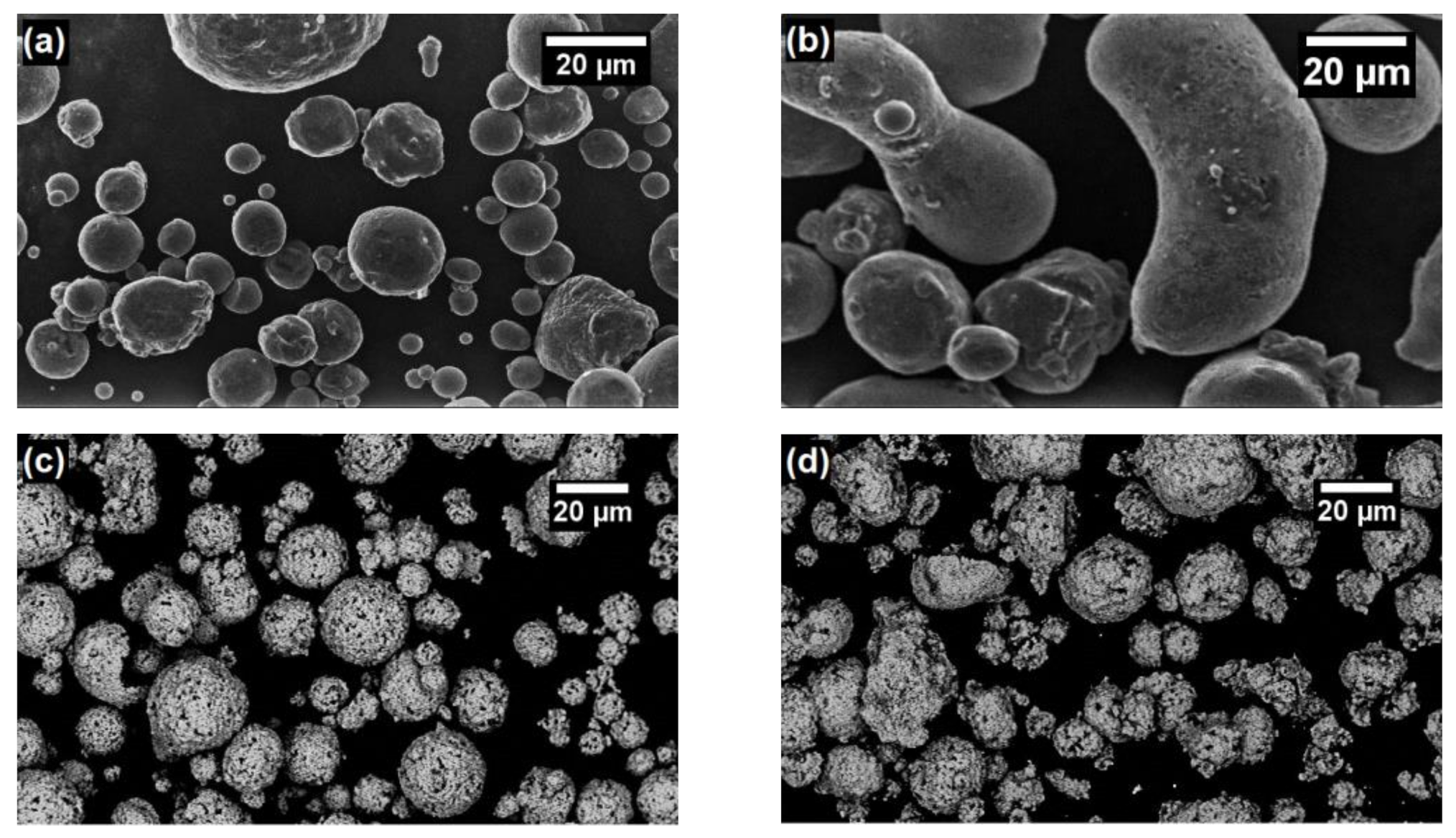
3.1. Characterization of Powders

The micrographs of feedstock powders are presented in Figure 2, indicating a higher spheroidicity for the Dycomet 1008 powder than for the maraging one and an identical shape for the carbides. The Dycomet 1008 and maraging chemical compositions are presented in Table 2, and their particle size distributions are shown in Figure 3, from where it can be seen that the maraging particles are slightly larger than the Dycomet 1008 particles and that the distribution curves for the carbides WC-12Co and WC-10Co4Cr are very similar.

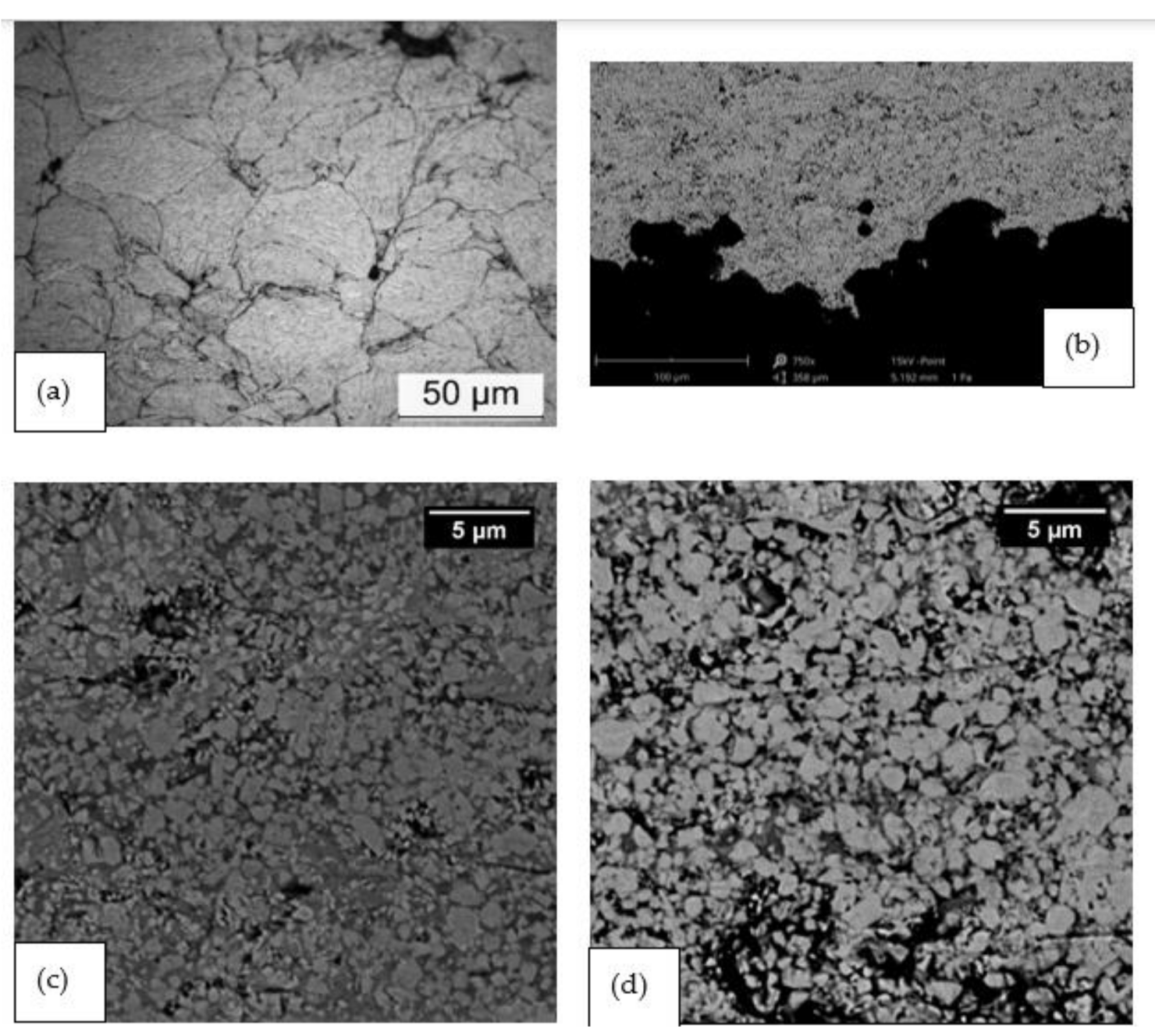
3.2. Characterization of Coatings

The images of coatings’ cross-sections are presented in Figure 4, where it is possible to observe that the particles deformed due to their impact at high velocity in CGS MAM maraging, resulting in a dense material, which was revealed by the etching (Figure 4a). The periphery of the maraging particles had severe grain deformation, while the center of the particles remained with an equiaxial microstructure, which is typical for CGS sprayed layers [16]. The porosity was calculated as a mean of 10 image analyses, and Figure 4 does not represent this average porosity value, which is indicated in Table 3. The average value of hardness of as-sprayed maraging was 378 HV0.3, and a gradient of hardness value was not observed from the material closer to the substrate to the region closer to the WC coating. The maraging deposition efficiency was 75%. The interface between the CGS sprayed maraging and the HVOF cermet is presented in Figure 4b, from where it is possible to interpret a good adhesion, without porosity or cracks on this interface.
The carbide coating micrographs are presented in Figure 4c,d for WC-12Co and WC-10Co4, respectively. Both coatings had porosity under 1% and hardness above 1200 HV0.3, as shown in Table 3, which is consonant with values published by other authors [45,46]. The morphology is composed of particles of WC, which is the lighter phase uniformly distributed in Figure 4c,d, and the metal matrix or binder, the darker phase in Figure 4c,d. The carbides presented were well adhered to the maraging, with no cracks or delamination, and visual uniformity of thickness, which was confirmed by the narrow range of thickness standard deviation values in Table 3, ±5 μm for WC-12Co and ±23 μm for WC-10Co4Cr coatings, which is under 10% of thickness variation. CGS MAM maraging had this level of thickness variation also.
The effectiveness of applying the Dycomet 1008 layer to improve the CGS MAM maraging adherence on the C-steel substrate was proven by the large thickness of maraging obtained, above 800 μm. A poor adherence makes it not possible to grow this amount of material on the substrate without delaminating or cracking in the interface coating/substrate, as tested previously by the authors. The adhesion testing with a couple of Dycomet 1008 plus maraging resulted in a value of 52 ± 6 MPa. Figure 5 clearly indicates that this Dycomet 1008 layer promotes the good adherence of the maraging, even showing clear bonding mechanisms of CGS adhesion, such as the severe plastic deformation of the C-steel substrate, which is related to the adiabatic shear instability (ASI), the jetting, and consequent interlocking [13,47,48].
The same HVOF process parameters were applied to spray both carbide powders, which have almost identical particle size distribution, as seen in Figure 4, and very close thickness values were obtained, as presented in Table 3. This indicates that the WC-12Co and WC-10Co4Cr had very similar deposition efficiency values, and no influence of the matrix composition was observed on the deposition efficiency.

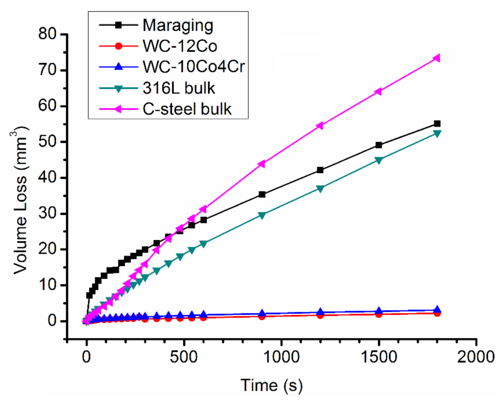
3.3. Wear Performance

The friction wear testing was performed on ball-on-disk testing and the CoF evolution between a WC-Co ball counterpart and the tested materials was plotted (Figure 6). The mean CoF values after the wear regimen stabilized are indicated in Table 4. The value indicated for the reference material 316L bulk, 0.67, is close to the value presented in the literature, 0.7 [16,49]. The CGS MAM maraging presented the highest CoF, 0.86, while the WC-10Co4Cr had the lowest, 0.14, among the evaluated materials.
CGS MAM maraging, 316L bulk, and C-steel bulk presented on the wear track both the abrasive and the adhesive wear mechanisms. The abrasive mechanism is evidenced by furrows in the direction of ball moving, indicated by arrows in Figure 7b. The adhesive wear mechanism results from the adhesion of some debris on the wear track, after severe deformation and oxidation, as revealed by EDS analysis. The darker areas in Figure 7b indicate this attached debris. This combination of mechanisms made the CoF values oscillate, as observed in the CoF curves for the CGS MAM maraging, 316L bulk, and C-steel bulk.
The WC-Co HVOF coatings under the ball-on-disk testing presented a very thin and shallow wear track, as indicated by arrows as the darker area in Figure 7a, which did not present oxidation, as revealed by EDS analysis. The WC-Co coatings resulted in a very low friction wear rate, highlighting the WC-12Co with 0.013 × 10⁻⁵ mm3·N−1·m−1, around 177 times lower than CGS MAM maraging and 1300 times lower than 316L bulk. This better performance in the friction testing indicates that both WC coatings can serve as friction wear protectors for CGS MAM maraging, as well as for 316L and C-steel bulk. In general, friction and wear of carbides are believed to result from three mechanisms, adhesion, plowing or abrasion, and asperity deformation [50]. In the present study, the wear track of both WC-Co coatings presented few marks of plowing and surface deformation, without any adhesion, which resulted in a very flat CoF curve for both cermets, as seen in Figure 6.
The abrasion rates from the rubber wheel testing (Table 4) indicated that WC-Co coatings were dozens of times more resistant than the maraging, C-steel bulk, and 316L bulk. The most relevant of these was the WC-12Co, with an abrasion rate of 0.76 × 10⁻⁵ mm3·N−1·m−1, which is even lower than that reported in the literature, close to 1.0 × 10⁻⁵ mm3·N−1·m−1 [28,51,52]. This behavior is also presented graphically in Figure 8 with the cermet curves appearing much flatter than those the other tested materials. The higher hardness of cermet coatings in comparison to the other tested materials (Table 3) is an explanation for their better abrasion resistance, as reported by Gee, Gant, and Roebuck [52] and Gant, Gee, and May [51], who presented an exponential relation between the volume loss and the material hardness in rubber wheel low-stress abrasion testing.
Evaluating the HVOF cermet coatings’ morphology in Figure 4, the WC-10Co4Cr presents larger WC particles than the WC-12Co, which is reflected in the abrasion rate, as explained by Gokul Lakshmi, Reddy, and Roy [53], who revealed that the abrasion resistance for low-stress testing increases with the amount of large hard particles. This is related to the incapacity of the erodents to penetrate the coating as they are fragmented and smashed by the coating’s hard carbides. Merrick and Miller [54] indicated that only abrasives that penetrate the coating with a depth larger than the size of the WC particles are capable of abrading the composite materials.
Regarding another wear mechanism, the erosion by water impact is relevant for structures exposed to water droplets at high velocities, such as wind turbine blades, steam turbines, gas turbine components, or airplane fuselages [30,31,55]. The jet erosion testing was performed, and the evolution of mass loss versus testing elapsed time is plotted in Figure 9, while the wear rate is presented in Table 4. The CGS MAM maraging had the highest erosion rate, more than 10 times that of the WC-10Co4Cr and 100 times that of the WC-12Co. The bulk reference materials had a lower erosion rate than the thermally sprayed materials, and among the bulks, 316L stainless steel had the smallest value, 2.55 mg·min−1. According to ASTM G73 [42], the testing ends at the rupture of the coating, which is clearly seen in the cermet curves, at 120 min for WC-10Co4Cr and 420 min for WC-12Co, since from these points their erosion rate curves follow the CGS MAM maraging slope.
The erosion mechanism presented in the literature for the water jet erosion is the same as that observed for the cavitation erosion [31]. The erosion slopes typically present three stages: the incubation, when the material absorbs energy and is not eroded; the second stage, characterized by the beginning of mass loss and the increment in the mass loss rate up to the maximum value; and the third stage, which is characterized as a regime of steady-state mass loss rate [56]. The thermally sprayed materials, maraging and cermets, did not have the incubation period; however, the C-steel bulk stayed in the incubation period for 240 min and the 316L bulk did not evolve to the second stage after 660 min, as interpreted visually from their slopes. Other authors reported this inexistence of incubation for thermally sprayed coatings under water erosion, such as HVOF and arc sprayed FeMnCrSi alloys [56], HVOF sprayed cermets and Ti alloys [31], and HVOF–kerosene fuel sprayed cermets [27].

3.4. Corrosion Behavior

For the evaluation of the performance of the materials in a corrosive media, 3.5 wt.% NaCl water solution, and to understand the effectiveness of applying WC coatings on CGS MAM maraging, as corrosion protection, potentiodynamic experiments were conducted with the as-sprayed maraging and WC-coated samples and the reference C-steel and 316L bulks. The polarization curves obtained in these experiments are shown in Figure 10. The potential of corrosion, Ecorr, and the corrosion current, Icorr, values characteristic for each material were calculated by Equation (2) and are presented in Table 5, as is the polarization resistance, Rp. A significant difference in these parameters can be observed between the sprayed materials and the bulks, with the 316L bulk as the noblest material, −179.80 mV, and the worst behavior for C-steel bulk, −753.97 mV. These results are consonant with those presented in the literature, −239 mV [16] and −260 mV [57] for 316L bulk and −726 mV [46] and −719 mV [58] for C-steel.
Regarding the sprayed materials, their results were lower than the 316L bulk stainless steel ones and higher than the C-steel bulk ones. All of the coatings had low porosity, which is mandatory for good corrosion protection of the substrate. Both WC HVOF coatings had higher Ecorr values than the CGS MAM maraging in 3.5% NaCl water solution, showing that these coatings could extend the service life of CGS MAM maraging parts when operating in this medium. The close, but different, values seen for the WC-12Co and WC-10Co4Cr are related to the binder material amount and composition, as reported by Bulnes et al. [46], who presented the metal matrix -10Co4Cr as nobler than the -12Co one for the studied hard coatings. Despite this, when the potential was shifted from the cathodic to the anodic region, the cermets had different behaviors, with the WC-12Co presenting lower Icorr than WC-10Co4Cr, which indicates slower corrosion for the WC-12Co under these polarization conditions.

4. Conclusions

Considering the microstructures characterized, the mechanical properties measured, and the wear and corrosion testing results for CGS MAM maraging and the HVOF cermet coatings, it is possible to conclude the following:
The production of a dense maraging part by CGS MAM on a C-steel substrate benefits from the previously deposited layer of CGS Dycomet, which improves the adhesion of the maraging sprayed by CGS.
The deposition of cermets, WC-12Co and WC-10Co4Cr, by HVOF on CGS MAM maraging results in well-adhered hard coatings, which improve the component’s wear resistance. The sliding wear and water erosion rates are reduced more than 100 times, while the abrasion wear rate is reduced almost 30 times. The potential of corrosion is also reduced, although the 316L bulk is still the noblest material among the evaluated samples and the C-steel bulk has the highest Ecorr.

Author Contributions

Conceptualization, R.F.V., A.S., and J.S.; funding acquisition, J.S. and I.G.C.; investigation, R.F.V. and A.S.; methodology, R.F.V., A.S., and J.S.; project administration, I.G.C.; writing—original draft preparation, R.F.V., A.S., J.S., and V.A.; writing—review and editing, R.F.V., A.S., and J.S.; supervision, I.G.C. All authors have read and agreed to the published version of the manuscript.

Funding

The authors wish to thank COMRDI16-1-0007-5 “RIS3CAT 3D TOOLING”.

Institutional Review Board Statement

Not applicable.

Informed Consent Statement

Not applicable.

Data Availability Statement

The data presented in this study are available on request from the corresponding author.

Conflicts of Interest

The authors declare no conflict of interest. The funders had no role in the design of the study; in the collection, analyses, or interpretation of data; in the writing of the manuscript; or in the decision to publish the results.

References

  1. Frazier, W.E. Metal additive manufacturing: A review. J. Mater. Eng. Perform. 2014, 23, 1917–1928. [Google Scholar] [CrossRef]
  2. Herzog, D.; Seyda, V.; Wycisk, E.; Emmelmann, C. Additive manufacturing of metals. Acta Mater. 2016, 117, 371–392. [Google Scholar] [CrossRef]
  3. Ahmed, G.M.S.; Badruddin, I.A.; Tirth, V.; Algahtani, A.; Ali, M.A. Wear resistance of maraging steel developed by direct metal laser sintering. Mater. Express 2020, 10, 1079–1090. [Google Scholar] [CrossRef]
  4. Pan, Z.; Ding, D.; Wu, B.; Cuiuri, D.; Li, H.; Norrish, J. Arc welding processes for additive manufacturing: A review. In Transactions on Intelligent Welding Manufacturing; Chen, S., Zang, Y., Feng, Z., Eds.; Springer: Singapore, 2018; pp. 3–24. ISBN 9789811053559. [Google Scholar]
  5. Karayel, E.; Bozkurt, Y. Additive manufacturing method and different welding applications. J. Mater. Res. Technol. 2020, 9, 11424–11438. [Google Scholar] [CrossRef]
  6. Li, W.; Yang, K.; Yin, S.; Yang, X.; Xu, Y.; Lupoi, R. Solid-state additive manufacturing and repairing by cold spraying: A review. J. Mater. Sci. Technol. 2018, 34, 440–457. [Google Scholar] [CrossRef]
  7. Assadi, H.; Kreye, H.; Gärtner, F.; Klassen, T. Cold spraying—A materials perspective. Acta Mater. 2016, 116, 382–407. [Google Scholar] [CrossRef] [Green Version]
  8. Oyinbo, S.T.; Jen, T.-C. A comparative review on cold gas dynamic spraying processes and technologies. Manuf. Rev. 2019, 6, 1–20. [Google Scholar] [CrossRef] [Green Version]
  9. Yin, S.; Cavaliere, P.; Aldwell, B.; Jenkins, R.; Liao, H.; Li, W. Cold spray additive manufacturing and repair: Fundamentals and applications. Addit. Manuf. 2018, 21, 628–650. [Google Scholar] [CrossRef]
  10. Bagherifard, S.; Monti, S.; Zuccoli, M.V.; Riccio, M.; Kondás, J.; Guagliano, M. Cold spray deposition for additive manufacturing of freeform structural components compared to selective laser melting. Mater. Sci. Eng. A 2018, 721, 339–350. [Google Scholar] [CrossRef]
  11. Raoelison, R.N.; Verdy, C.; Liao, H. Cold gas dynamic spray additive manufacturing today: Deposit possibilities, technological solutions and viable applications. Mater. Des. 2017, 133, 266–287. [Google Scholar] [CrossRef]
  12. Yan, X.; Huang, C.; Chen, C.; Bolot, R.; Dembinski, L.; Huang, R.; Ma, W.; Liao, H.; Liu, M. Additive manufacturing of WC reinforced maraging steel 300 composites by cold spraying and selective laser melting. Surf. Coat. Technol. 2019, 371, 161–171. [Google Scholar] [CrossRef]
  13. Bae, G.; Kumar, S.; Yoon, S.; Kang, K.; Na, H.; Kim, H.; Lee, C. Bonding features and associated mechanisms in kinetic sprayed titanium coatings. Acta Mater. 2009, 57, 5654–5666. [Google Scholar] [CrossRef]
  14. Yin, S.; Cizek, J.; Cupera, J.; Hassani, M.; Luo, X.; Jenkins, R.; Xie, Y.; Li, W.; Lupoi, R. Formation conditions of vortex-like intermixing interfaces in cold spray. Mater. Des. 2021, 200, 1–10. [Google Scholar] [CrossRef]
  15. Cormier, Y.; Dupuis, P.; Jodoin, B.; Corbeil, A. Pyramidal fin arrays performance using streamwise anisotropic materials by cold spray additive manufacturing. J. Therm. Spray Technol. 2016, 25, 170–182. [Google Scholar] [CrossRef] [Green Version]
  16. Vaz, R.F.; Silvello, A.; Sanchez, J.; Albaladejo, V.; Cano, I.G. The influence of the powder characteristics on 316L stainless steel coatings sprayed by cold gas spray. Coatings 2021, 11, 168. [Google Scholar] [CrossRef]
  17. Jiao, Z.B.; Luan, J.H.; Miller, M.K.; Chung, Y.W.; Liu, C.T. Co-precipitation of nanoscale particles in steels with ultra-high strength for a new era. Mater. Today 2017, 20, 142–154. [Google Scholar] [CrossRef]
  18. Würzinger, P.; Rabitsch, R.; Meyer, W. Production of maraging steel grades and the influence of specified and nonspecified elements for special applications. J. Mater. Sci. 2004, 39, 7295–7302. [Google Scholar] [CrossRef]
  19. Chen, C.; Yan, X.; Xie, Y.; Huang, R.; Kuang, M.; Ma, W.; Zhao, R.; Wang, J.; Liu, M.; Ren, Z.; et al. Microstructure evolution and mechanical properties of maraging steel 300 fabricated by cold spraying. Mater. Sci. Eng. A 2019, 743, 482–493. [Google Scholar] [CrossRef]
  20. Chen, C.; Xie, Y.; Yan, X.; Huang, R.; Kuang, M.; Ma, W.; Zhao, R.; Wang, J.; Liu, M.; Ren, Z.; et al. Cold sprayed WC reinforced maraging steel 300 composites: Microstructure characterization and mechanical properties. J. Alloys Compd. 2019, 785, 499–511. [Google Scholar] [CrossRef]
  21. Turk, C.; Zunko, H.; Aumayr, C.; Leitner, H.; Kapp, M. Advances in Maraging steels for additive manufacturing. BHM Berg- und Hüettenmännische Mon. 2019, 164, 112–116. [Google Scholar] [CrossRef] [Green Version]
  22. Jägle, E.A.; Sheng, Z.; Kürnsteiner, P.; Ocylok, S.; Weisheit, A.; Raabe, D. Comparison of maraging steel micro- and nanostructure produced conventionally and by laser additive manufacturing. Materials 2017, 10, 8. [Google Scholar] [CrossRef] [Green Version]
  23. Takata, N.; Nishida, R.; Suzuki, A.; Kobashi, M.; Kato, M. Crystallographic features of microstructure in Maraging steel fabricated by selective laser melting. Metals 2018, 8, 440. [Google Scholar] [CrossRef] [Green Version]
  24. Ansell, T.Y.; Ricks, J.P.; Park, C.; Tipper, C.S.; Luhrs, C.C. Mechanical properties of 3D-printed maraging steel induced by environmental exposure. Metals 2020, 10, 218. [Google Scholar] [CrossRef] [Green Version]
  25. Sun, K.; Peng, W.; Wei, B.; Yang, L.; Fang, L. Friction and wear characteristics of 18Ni(300) maraging steel under high-speed dry sliding conditions. Materials 2020, 13, 1485. [Google Scholar] [CrossRef] [Green Version]
  26. Wang, H.; Qiu, Q.; Gee, M.; Hou, C.; Liu, X.; Song, X. Wear resistance enhancement of HVOF-sprayed WC-Co coating by complete densification of starting powder. Mater. Des. 2020, 191, 1–13. [Google Scholar] [CrossRef]
  27. Lamana, M.S.; Pukasiewicz, A.G.M.; Sampath, S. Influence of cobalt content and HVOF deposition process on the cavitation erosion resistance of WC-Co coatings. Wear 2018, 398–399, 209–219. [Google Scholar] [CrossRef]
  28. Magnani, M.; Suegama, P.H.; Espallargas, N.; Dosta, S.; Fugivara, C.S.; Guilemany, J.M.; Benedetti, A. V Influence of HVOF parameters on the corrosion and wear resistance of WC-Co coatings sprayed on AA7050 T7. Surf. Coat. Technol. 2008, 202, 4746–4757. [Google Scholar] [CrossRef]
  29. Pulsford, J.; Venturi, F.; Kamnis, S.; Hussain, T. Sliding wear behaviour of WC-Co reinforced NiCrFeSiB HVOAF thermal spray coatings against WC-Co and Al2O3 counterbodies. Surf. Coat. Technol. 2020, 386, 1–11. [Google Scholar] [CrossRef]
  30. Mahdipoor, M.S.; Tarasi, F.; Moreau, C.; Dolatabadi, A.; Medraj, M. HVOF sprayed coatings of nano-agglomerated tungsten-carbide/cobalt powders for water droplet erosion application. Wear 2015, 330–331, 338–347. [Google Scholar] [CrossRef]
  31. Shipway, P.H.; Gupta, K. The potential of WC-Co hardmetals and HVOF sprayed coatings to combat water-droplet erosion. Wear 2011, 271, 1418–1425. [Google Scholar] [CrossRef]
  32. ASTM. B822-02—Standard Test. Method for Particle Size Distribution of Metal. Powders and Related Compounds by Laser Scattering; ASTM International: West Conshohocken, PA, USA, 2002. [Google Scholar]
  33. ISO. 17836:2004—Thermal Spraying—Determination of Deposition Efficiency for Thermal Spraying; ISO: Geneva, Switzerland, 2004. [Google Scholar]
  34. ASTM. E1920-03—Standard Guide for Metallographic Preparation of Thermal Sprayed Coatings; ASTM International: West Conshohocken, PA, USA, 2003. [Google Scholar]
  35. ASTM. E3-01—Standard Guide for Preparation of Metallographic Specimens; ASTM International: West Conshohocken, PA, USA, 2001. [Google Scholar]
  36. ASTM. B487-85—Standard Test. Method for Measurement of Metal and Oxide Coating Thickness by Microscopical Examination of a Cross Section; ASTM International: West Conshohocken, PA, USA, 2002. [Google Scholar]
  37. ASTM. E2109-01—Standard Test. Methods for Determining Area Percentage Porosity in Thermal Sprayed Coatings; ASTM International: West Conshohocken, PA, USA, 2002. [Google Scholar]
  38. ASTM. E384-99—Standard Test. Method for Microindentation Hardness of Materials; ASTM International: West Conshohocken, PA, USA, 2000. [Google Scholar]
  39. ASTM. C633-13—Standard Test. Method for Adhesion or Cohesion Strength of Thermal Spray Coatings; ASTM International: West Conshohocken, PA, USA, 2017. [Google Scholar]
  40. ASTM. G65-00—Standard Test. Method for Measuring Abrasion Using the Dry Sand Rubber Wheel Apparatus; ASTM International: West Conshohocken, PA, USA, 2000. [Google Scholar]
  41. ASTM. G99-04—Standard Test. Method for Wear Testing with A Pin-on-Disk Apparatus; ASTM International: West Conshohocken, PA, USA, 2004. [Google Scholar]
  42. ASTM. G73-10—Standard Test. Method for Liquid Impingement Erosion Using Rotating Apparatus; ASTM International: West Conshohocken, PA, USA, 2010. [Google Scholar]
  43. ASTM. G59-97—Standard Test. Method for Conducting Potentiodynamic Polarization Resistance Measurements; ASTM International: West Conshohocken, PA, USA, 1997. [Google Scholar]
  44. ASTM. G102-89—Standard Practice for Calculation of Corrosion Rates and Related Information from Electrochemical Measurements; ASTM International: West Conshohocken, PA, USA, 1999. [Google Scholar]
  45. Ahmed, R.; Vourlias, G.; Algoburi, A.; Vogiatzis, C.; Chaliampalias, D.; Skolianos, S.; Berger, L.-M.; Paul, S.; Faisal, N.H.; Toma, F.-L.; et al. Comparative study of corrosion performance of HVOF-sprayed coatings produced using conventional and suspension WC-Co feedstock. J. Therm. Spray Technol. 2018, 27, 1579–1593. [Google Scholar] [CrossRef] [Green Version]
  46. Bulnes, A.G.; Fuentes, V.A.; Cano, I.G.; Dosta, S. Understanding the influence of high velocity thermal spray techniques on the properties of different anti-wear WC-based coatings. Coatings 2020, 10, 1157. [Google Scholar] [CrossRef]
  47. Grujicic, M.; Zhao, C.L.; DeRosset, W.S.; Helfritch, D. Adiabatic shear instability based mechanism for particles/substrate bonding in the cold-gas dynamic-spray process. Mater. Des. 2004, 25, 681–688. [Google Scholar] [CrossRef]
  48. Ko, K.H.; Choi, J.O.; Lee, H. Intermixing and interfacial morphology of cold-sprayed Al coatings on steel. Mater. Lett. 2014, 136, 45–47. [Google Scholar] [CrossRef]
  49. Qin, W.; Kang, J.; Li, J.; Yue, W.; Liu, Y.; She, D.; Mao, Q.; Li, Y. Tribological behavior of the 316L stainless steel with heterogeneous lamella structure. Materials 2018, 11, 1839. [Google Scholar] [CrossRef] [Green Version]
  50. Jianxin, D.; Hui, Z.; Ze, W.; Yunsong, L.; Jun, Z. Friction and wear behaviors of WC/Co cemented carbide tool materials with different WC grain sizes at temperatures up to 600 °C. Int. J. Refract. Met. Hard Mater. 2012, 31, 196–204. [Google Scholar] [CrossRef]
  51. Gant, A.J.; Gee, M.G.; May, A.T. The evaluation of tribo-corrosion synergy for WC-Co hardmetals in low stress abrasion. Wear 2004, 256, 500–516. [Google Scholar] [CrossRef]
  52. Gee, M.G.; Gant, A.; Roebuck, B. Wear mechanisms in abrasion and erosion of WC/Co and related hardmetals. Wear 2007, 263, 137–148. [Google Scholar] [CrossRef]
  53. Gokul Lakshmi, S.; Reddy, G.M.; Roy, M. A Comparison of Wear Due to Abrasion of WC–Ni Coatings on Aluminium Alloy Sprayed by HVOF and Detonation Gun. Trans. Indian Inst. Met. 2018, 71, 1389–1399. [Google Scholar] [CrossRef]
  54. Merrick, S.J.; Miller, R.F. The role of carbides in iron base hardsurfacing deposits. In Proceedings of the Advances in Thermal Spraying; Pergamon Press: Montreal, QC, Canada, 1986; pp. 633–642. [Google Scholar]
  55. Ibrahim, M.E.; Medraj, M. Water droplet erosion ofwind turbine blades: Mechanics, testing, modeling and future perspectives. Materials 2020, 13, 157. [Google Scholar] [CrossRef] [Green Version]
  56. Vaz, R.F.; Sucharski, G.B.; Chicoski, A.; Siqueira, I.B.A.F.; Tristante, R.; Pukasiewicz, A.G.M. Comparison of FeMnCrSi cavitation resistance coatings deposited by Twin-Wire Electric Arc and High-Velocity Oxy-Fuel processes. J. Therm. Spray Technol. 2021, 30, 754–771. [Google Scholar] [CrossRef]
  57. Bellie, V.; Suresh, J.; Ragunath, L. HVOF sprayed mullite coatings for use in extreme environments. J. Therm. Spray Eng. 2020, 2, 43–49. [Google Scholar] [CrossRef]
  58. Othman, N.K.; Yahya, S.; Awizar, D.A. Anticorrosive properties of nano silicate from paddy husk in salt medium. Sains Malays. 2016, 45, 1253–1258. [Google Scholar]
Figure 1. (a) Jet erosion equipment; (b) Detail of the rotating arm, where the sample is fixed.
Metals 11 01092 g001
Figure 2. SEM (scanning electron microscope) images of feedstock powders. (a) Maraging, (b) Dycomet 1008, (c) WC-12Co, (d) WC-10Co4Cr.
Metals 11 01092 g002
Figure 3. Feedstock powder particle size distributions.
Metals 11 01092 g003
Figure 4. (a) OM (optical microscopy) image of CGS MAM maraging after etching. SEM images of (b) interface maraging (darker area) and cermet (lighter area); (c) WC-12Co, magnification 7500×; (d) WC-10Co4Cr.
Metals 11 01092 g004
Figure 5. OM image of the Dycomet 1008 layer. (1) Maraging, (2) Dycomet 1008, (3) C-steel substrate.
Metals 11 01092 g005
Figure 6. CoF (coefficient of friction) results from ball-on-disk testing.
Metals 11 01092 g006
Figure 7. SEM images of worn tracks from ball-on-disk testing. (a) WC-12Co, with arrows indicating the wear track. (b) 316L bulk, with the arrows indicating furrows in the direction of ball moving.
Metals 11 01092 g007
Figure 8. Accumulated volume loss from abrasion testing.
Metals 11 01092 g008
Figure 9. Accumulated mass loss from jet erosion testing.
Metals 11 01092 g009
Figure 10. Tafel slopes from potentiodynamic experiments.
Metals 11 01092 g010
Table 1. Spraying parameters. CGS: cold gas spray. HVOF: high-velocity oxy-fuel.
ParameterCGSHVOF
N2 Pressure (MPa)7.0/
N2 Temperature (°C)975/
H2 Pressure (MPa)/1.0
O2 Temperature (MPa)/1.2
Standoff Distance (mm)25225
Powder Feeding (g·s−1)0.430.50
Robot Speed (m·s−1)0.50.5
Layers410
Table 2. CGS feedstock material chemical compositions.
PowderNominal Composition (wt.%)
CrNiMoMnCoTiAlFe
Dycomet 100817.84.914.72.7---Bal.
Maraging7.511.43.31.63.91.81.1Bal.
Table 3. Material characteristics and properties.
MaterialThickness
(μm)
Hardness
(HV0.3)
Porosity
(%)
Maraging874 ± 71378 ± 63<1.0
WC-12Co242 ± 51249 ± 72<1.0
WC-10Co4Cr234 ± 231345 ± 133<1.0
316L bulk-350 ± 13-
C-steel bulk-241 ± 9-
Table 4. Wear testing results.
MaterialAbrasion Rate
(mm3·N−1·m−1)
CoF
(N N−1)
Friction Wear Rate
(mm3·N−1·m−1)
Jet Erosion Rate
(mg·min−1)
Maraging21.61 × 10−50.86 ± 0.082.302 × 10−51654.67 ± 115.64
WC-12Co0.76 × 10−50.38 ± 0.030.013 × 10−515.66 ± 1.69
WC-10Co4Cr1.29 × 10−50.14 ± 0.010.032 × 10−5137.33 ± 3.46
316L bulk16.73 × 10−50.67 ± 0.1117.051 × 10−52.55 ± 0.00
C-steel bulk23.94 × 10−50.46 ± 0.032.841 × 10−569.88 ± 3.22
Table 5. Results of potentiodynamic experiments.
MaterialCurrent Density
Icorr (μA·cm−2)
Potential of Corrosion
Ecorr (mV)
Polarization Resistance
Rp (kΩ)
Maraging0.41−457.1939.08
WC-12Co1.47−381.5016.34
WC-10Co4Cr1.79−339.4810.25
316L bulk0.07−179.8058.00
C-steel bulk0.53−753.978.08
Publisher’s Note: MDPI stays neutral with regard to jurisdictional claims in published maps and institutional affiliations.

