
Evaporator Frosting in Refrigerating Appliances: Fundamentals and Applications
by
Christian J. L. Hermes
1,*, 
Joel Boeng
1,
Diogo L. da Silva
2,
Fernando T. Knabben
1 and
Andrew D. Sommers
3 1
POLO Laboratories, Department of Mechanical Engineering, Federal University of Santa Catarina, Florianópolis 88040-900, Brazil
2
Laboratory of Vehicular Refrigeration, Department of Mobility Engineering, Federal University of Santa Catarina, Joinville 89218-035, Brazil
3
Department of Mechanical and Manufacturing Engineering, Miami University, 56 Garland Hall, 650 East High Street, Oxford, OH 45056, USA
*
Author to whom correspondence should be addressed.
Energies 2021, 14(18), 5991; https://doi.org/10.3390/en14185991
Submission received: 19 July 2021
/
Revised: 13 August 2021
/
Accepted: 17 August 2021
/
Published: 21 September 2021
(This article belongs to the Special Issue Heat Exchangers: Cooling and Heating Systems)
Abstract
:Modern refrigerators are equipped with fan-supplied evaporators often tailor-made to mitigate the impacts of frost accretion, not only in terms of frost blocking, which depletes the cooling capacity and therefore the refrigerator coefficient of performance (COP), but also to allow optimal defrosting, thereby avoiding the undesired consequences of condensate retention and additional thermal loads. Evaporator design for frosting conditions can be done either empirically through trial-and-error approaches or using simulation models suitable to predict the distribution of the frost mass along the finned coil. Albeit the former is mandatory for robustness verification prior to product approval, it has been advocated that the latter speeds up the design process and reduces the costs of the engineering undertaking. Therefore, this article is aimed at summarizing the required foundations for the design of efficient evaporators and defrosting systems with minimized performance impacts due to frosting. The thermodynamics, and the heat and mass transfer principles involved in the frost nucleation, growth, and densification phenomena are presented. The thermophysical properties of frost, such as density and thermal conductivity, are discussed, and their relationship with refrigeration operating conditions are established. A first-principles model is presented to predict the growth of the frost layer on the evaporator surface as a function of geometric and operating conditions. The relation between the microscopic properties of frost and their macroscopic effects on the evaporator thermo-hydraulic performance is established and confirmed with experimental evidence. Furthermore, different defrost strategies are compared, and the concept of optimal defrost is formulated. Finally, the results are used to analyze the efficiency of the defrost operation based on the net cooling capacity of the refrigeration system for different duty cycles and evaporator geometries.
1. Introduction
Frost is likely to build up whenever moist air flows over a chilled surface whose temperature is sub-zero and below the local dewpoint of the air stream. Such a combination of psychrometric conditions and a cold substrate give rise to frosted media that can be observed in different engineering applications, spanning from agriculture to aerospace devices. A niche of particular interest lies in the evaporators of household and commercial refrigerating appliances, where the performance is dramatically affected by frost accretion, which not only imposes an additional thermal resistance to the heat flux but also diminishes the air flow passage, thus decreasing the air flow rate for a fixed pumping power. Either way, the evaporator heat duty (also known as the cooling capacity) is depleted over time, thereby demanding longer compressor cycles (and therefore more energy input) to accomplish the same refrigerating effect [1].
According to recent data from the International Institute of Refrigeration [2], refrigeration, air conditioning, and heat pump systems consume about 17% of the electric energy produced worldwide, with the residential sector responsible for nearly half of it. Such a large figure is due to a combination of factors, such as the enormous number of refrigerators in operation (around 1.5 billion), the relatively low efficiency of the refrigeration cycle (approximately 20% of that of a Carnot refrigerator), and also operating issues such as door openings and, consequently, evaporator frosting [3]. To mitigate evaporator frosting issues, periodic defrosting operations are carried out using the so-called defrost systems. In most applications, the defrost system employs electric heaters for melting the ice, albeit alternative strategies such as hot-gas and reverse cycles, and fan delays can also be adopted. For doing so, the appliance must be switched off for a certain period of time, while the defrosting process takes place not only consuming energy but also increasing the cabinet thermal loads that shall be lately removed by the cooling system, thus increasing even more the energy penalty. For instance, in the case of an electric heater, just a small part (roughly 20%) of the power supplied to the defrost system is actually used to melt the ice [4].
Moreover, the nature of the phenomena related to evaporator frosting and defrosting in refrigerating appliances, such as conjugated heat and mass transfer with phase-change on and within porous media of complex geometries, may turn the optimal design of heat exchangers for frosting conditions into a burdensome task if no proper prediction tools are made available. Moreover, in addition to the needs of the refrigeration industry, the beauty of the physics involved in frost nucleation, growth, and densification is also compelling, motivating researchers around the world to endeavor into this field. Figure 1, for instance, shows that the number of research papers with terms related to ‘‘frost” or “defrost” and ‘‘heat exchanger” or ‘‘evaporator” has grown exponentially over the past 20 years, revealing a steadily-increasing interest in frost formation.
The literature is well-served in review papers concerning the fundamentals of evaporator frosting, not only in terms of first-principles models for frost growth and densification, but mostly related to the thermophysical properties of mature frosts, such as density and thermal conductivity, and their dependence on the surface characteristics [5,6]. Rather than putting forward another critical review of the open literature, the present communication summarizes the key fundamental aspects of frost formation that the cooling engineer must be acquainted with for designing new evaporators and better defrost systems. The paper starts with the very first principles of frost build-up, spanning from the nucleation process to the growth and densification of a mature frost layer. Later, simulation models and optimization techniques for designing evaporators working under frosting and defrosting conditions are also explored.
2. Frost Fundamentals
2.1. Background
Ice is water in the solid-state. As shown in Figure 2, depending on the thermodynamic condition (temperature and pressure), fifteen different forms of ice can be observed [7]. On the other hand, frost is a porous medium comprised of ice crystals and moist air formed due to a very particular set of surface and psychrometric conditions. As depicted in Figure 3, when moist air flows over a chilled surface, either condensation or freezing may occur. If the surface temperature is below the dewpoint of the moist air and above the water freezing point, moisture condensation may occur. However, if the surface temperature is below the dewpoint and below the freezing point, the water vapor may condense and freeze. Nevertheless, if both the surface temperature and the dewpoint are below the freezing point, vapor desublimation into solid may take place. The latter is the most likely condition for the accretion of a frost layer, being attained at the solid-vapor boundary below the triple point, as illustrated in Figure 2.
The phase diagram depicts only the lowest-energy state boundaries between solid, liquid, and vapor phases, notwithstanding the non-equilibrium in each phase transition, which can be represented by the band of metastability illustrated in Figure 4. In this case, the nucleation process is only triggered when the embryo is cooled down past a certain energy barrier, defining a fixed amount of supercooling required for the onset of the phase change. In the psychrometric chart illustrated in Figure 4, one can see the existence of a metastable state characterized by a certain degree of supercooling (∆Tsup) in a vapor supersaturation that corresponds to the absolute humidity potential that drives the mass transfer process (∆ωsup, also named supersaturation degree). In a nutshell, the nucleation can be represented by three distinct psychrometric processes [8], two of them occurring simultaneously: first, water vapor is cooled down in the boundary layer (A→A’), then heat and mass transfer take place, cooling down the water vapor in air (A’→B) and dehumidifying the air stream as the phase change goes on (B→C). The overall amount of energy to be removed is a combination of sensible heat (cp∆Tsup) and latent counterparts (isv∆ωsup), where cp and isv are respectively the specific heat of moist air and the latent heat of desublimation [8]. In order to quantify the amount of supercooling/supersaturation required for the onset of phase transition, classic nucleation theory shall be invoked.
2.2. Crystal Nucleation
Nucleation is initiated when the amount of energy removed from an embryo, i.e., a cluster of water molecules, is high enough to surpass a certain energy barrier related to the supercooled/supersaturated metastable states of Figure 4. Nucleation is called homogeneous when the phase change occurs with no contact with solid boundaries, or heterogeneous when there is an interface between the vapor and a substrate (a typical condition of refrigerator evaporators), as shown in Figure 5. A hemispherical shape of radius r is considered as the cluster tends towards a state of minimum energy, seeking the smallest surface area for a given volume. On the one hand, energy must be removed to promote the phase change of the volume (which follows the r3 scale) while, on the other hand, energy is required to form a new interface. In Figure 5, Ase and γse represent the surrounding-embryo interface area and the embryo surface energy, respectively, whereas γew and γsw stand for the surface energies at the embryo-wall and surrounding-wall interfaces, respectively, and Aew is the embryo-wall interface area. An energy balance at the embryo surface provides the net energy barrier required to form a new interface, yielding γse Ase − (γsw − γew) Aew (which follows the r2 scale). Therefore, an optimum embryo size (i.e., radius) must exist that minimizes the energy barrier. Piucco et al. [8] expressed the minimum energy barrier for the onset of nucleation as a function of the supersaturation degree and surface static contact angle, θ = cos−1(γsw − γew)/γse, yielding,
where ωs and ωsat,e are the humidity ratio of the surrounding air and that of the saturated air at the embryo temperature Te, respectively, ρi is the density of ice, and M and R are the molar mass and the gas constant for water, respectively. It should be noted that albeit Equation (1) was derived for heterogeneous nucleation on smooth surfaces, the energy barrier for homogeneous nucleation can be retrieved by setting θ = 180° in Equation (1). An inspection of Equation (1) also concludes that it is much easier to initiate heterogeneous nucleation than homogeneous nucleation, as evidenced by ∆Ghet < ∆Ghom.
Becker and Doring [9] proposed that the minimum energy barrier holds an exponential relationship with the so-called embryo formation rate for heterogeneous nucleation, I, which is a probability function, so that ∆Gmin ≈ −k Te ln(I/I0), where I0 = 1025 embryo/cm2s is a kinetic constant of desublimation, and k = 1.381 × 10⁻²³ J K−1 is the Boltzmann constant [10]. With I = 2.2 embryo/cm2s, observed experimentally by Volmer and Flood [11] as the critical embryo formation rate for homogeneous nucleation, the Becker–Doring theory can be used together with Equation (1) to come out with the threshold for the onset of nucleation expressed in terms of the supercooling degree as a function of the contact angle, as illustrated in Figure 6. Due to the stochastic nature of the process, reflected in the Becker–Doring formulation, the curve in Figure 6 divides the domain into two regions, with the upper one indicating the conditions when frost is most likely to occur and the lower region indicating the opposite. Moreover, one can notice in Figure 6 that the energy barrier for frosting on super-hydrophilic surfaces (θ⟶0°) is quite low, requiring virtually no supercooling for the onset of nucleation. On the other hand, the highest supercooling is observed for superhydrophobic surfaces (θ⟶180°), although a plateau around ∆Tsup ≈ 22 K is observed for θ > 135° [12]. This high initial energy barrier can lead to a delay in the onset of frosting on superhydrophobic surfaces by as much as one hour [13,14,15]. In practical terms, this barrier to frosting is even more attenuated in the case of non-smooth surfaces typical of refrigeration applications, as the surface roughness is likely to favor the onset of nucleation due to the reduction on the interface area, i.e., less energy required to form a new interface [8,16].
2.3. Frost Build-Up
The frost formation over a flat surface can be divided into several steps [17], as schematized in Figure 7. After the nucleation (1), the embryo starts growing (2). During this stage, the surface wettability can influence the size and shape of the growing embryo. Its surface area and temperature increase as it grows, requiring a higher amount of energy withdrawal to keep growing. When such amount becomes higher than the amount required for new nucleation, the primary embryo stops growing, and a secondary one emerges at a new site on the surface of the original embryo (3). Once again, the new embryo grows (4) so that successive embryo nucleation and crystal growth cycles (5, 6) go on until a mature layer of frost is formed (7). Stages (3) to (6) are called the early crystal growth period and are characterized by the morphology of the ice crystals.
Nakaya [18] discovered that ice crystals grow in distinct shapes (morphologies) depending on the psychrometric conditions, especially on the temperature and supersaturation of the air stream [19]. The pioneering observations from Nakaya [18], and subsequently from Kobayashi [20,21,22] and Magono and Lee [23], led to frost morphology maps like that illustrated in Figure 8, which shows the crystal shapes that grow as a function of surface temperature (that sets whether ice crystals will grow into plates or columns) and water vapor supersaturation (which determines the complexity of the structures).
According to the theory proposed by Kuroda and Lacmannn [24], the variations observed in the growth patterns of ice crystals may be explained by a quasi-liquid layer on the surface of the crystals. Such a layer has properties like water in the liquid phase, as it contains atoms with greater mobility than those inside the crystal. The theory considers a strong effect of the temperature of the surroundings on the properties and thickness of the quasi-liquid layer on the basal and prism facets of the crystal, favoring the growth of the crystal in preferential directions, according to the psychrometric conditions of the environment. Later, the growth rate of the different faces of ice crystals was measured experimentally by Libbrecht and Yu [25] and showed good agreement with the quasi-liquid layer theory.
As shown in Figure 7, one can notice that from stage (7) on, a mature layer of frost keeps growing and densifying due to simultaneous heat and mass transfer phenomena on and within the porous medium. This is illustrated in Figure 9. In general, the thickness of a growing frost layer follows the square root of time rule, as shown in Figure 10, due to the diffusive nature of the heat and mass transport inside the frost layer [26].
Several distinct frost formation models have been proposed in the last fifty years, each with its strengths and drawbacks, as summarized in Table 1. O’Neal [27], for instance, noticed that the frost accretion could be modeled as two simultaneous processes, namely growth and densification, that increase the thickness and the density of the frost layer. In the following decades, several studies advanced his approach. Nevertheless, despite the known significance and relevance of a supersaturated air-frost interface in the frost nucleation and growth process [28], the air-frost interface condition had been treated as saturated until recent times.
In general, frost formation models have been formulated based upon the following key assumptions [17]: (i) quasi-steady-state regime, (ii) one-dimensional diffusion within the frost layer, (iii) uniform frost thickness, (iv) constant properties, and (v) Lewis analogy. Hence, a mass balance on the frost layer of Figure 9 yields,
where mf is the vapor mass flux going into the frosted medium, and xf is the frost layer thickness. Defining the space-averaged frost density, Equation (2) can be written in terms of two mass fluxes as follows:
where the first term of the right-hand side stands for the frost growth rate, whereas the second term is responsible for the densification as water vapor diffuses inside the frost layer, changing phase into ice crystals within the porous medium, thereby reducing the frost layer porosity, ε = (ρf − ρi)/(ρa − ρi). In general, Equation (3) can be easily integrated using an explicit, forward Euler approach to come out with the time evolution of the frost thickness, xf.
Additionally, the mass flux can be expressed in terms of the convective mass transfer coefficient, hm, such that mf = hm (ωa − ωs), which can be related to the heat transfer coefficient, h, using the so-called Lewis analogy, Nu/Pr1/3 = Sh/Sc1/3 [55], where Nu, Sh, Pr, and Sc are the Nusselt, Sherwood, Prandtl and Schmidt numbers, respectively. Therefore, the mass transfer coefficient can be expressed by hm = h/(cp Le2/3), where the Lewis number, Le = Sc/Pr = α/D, may be obtained either from empirical correlations [39,56] or assumed to be unity [32,43,47].
Solution of the overall mass balance requires information about the thermodynamic properties at the air-frost interface. For doing so, Lee et al. [39] suggested the following first-order reaction model for the mass diffusion in the frost layer,
where Df = Dε/δ is the effective diffusivity of the water vapor in air, δ is the tortuosity of the frosted medium, and λ is the desublimation coefficient obtained from the solution of Equation (4) subjected the following boundary conditions: ω(x = 0) = ωw, (dω⁄dx)x = 0= 0 and ω(x = xf) = ωs, yielding Ha = xf (λDf)1/2 = cosh−1(ωs⁄ωw), where Ha is the Hatta number, representing the ratio between the time scale of diffusion and desublimation. Albeit a saturation boundary condition was used in this approach, more sophisticated models rely on supersaturated boundary conditions at the air-frost interface [49,51,56].
Similarly, an energy balance is invoked to come out with the temperature distribution along the frost layer,
where kf is the effective thermal conductivity of the porous medium. Considering a prescribed temperature condition at the surface, T(x = 0) = Tw, and the heat flux continuity at the frost surface, kf (dT⁄dx)x = xf = q + mf isv, where q = h(Ta − Ts) is the sensible heat flux to the frost surface, and the temperature of the frost surface can be expressed as Ts = Tw + (q + mf isv)/kf + ρa ωw [1 − cosh(Ha)] isv Df ⁄kf.
2.4. Thermophysical Properties
The model closure relies on empirical information for calculating the thermophysical properties of frost, namely the density and the thermal conductivity. Some key correlations for the latter were summarized by Negrelli and Hermes [57]. They also proposed a dimensionless semi-empirical model for the thermal conductivity as a function of the porosity of the frosted medium, as follows:
where the coefficients of Equation (6) were fitted to the experimental data according to the frost morphology: needles and sheaths (−10 < Tw < −4 °C, a = 1.576, b = 0.797), plates and dendrites (−19 < Tw < −10 °C, a = 1.594, b = 0.761), and sheaths (−30 < Tw < −19 °C, a = 1.035, b = 0.797). Equation (6) is valid for wall surface temperatures ranging from −30 to −4 °C, and frost porosities spanning from ε = 0.50 to 0.95. In a follow-up study, Negrelli et al. [58] advanced a simulation model for predicting the thermal conductivity of frost for various operational conditions and, therefore, distinct frost morphologies. The frost growth was modeled using fractal theory, particularly the diffusion-limited aggregation approach, which forms heterogeneous porous media that emulate the morphology of the frost layer, as depicted in Figure 11. A comparison between the different images in Figure 11 shows that the model can simultaneously reproduce both the growth and densification of the frost layer. The effective thermal conductivity of frost was calculated from an inverse solution of the heat diffusion problem using a finite-volume method, agreeing with the experimental data from [59] to within ±15%. More recently, Hosseini et al. [60] adopted a genetic programming approach to put forward semi-empirical correlations for the thermal conductivity based on dimensionless parameters such as the frost porosity and the Reynolds, modified Jakob and Fourier numbers.
Similarly, some key correlations for the frost density were summarized by Hermes et al. [61], spanning the literature from the pioneering work of Hayashi [35], who introduced an exponential relation between the frost density and the frost surface temperature. Hermes et al. [61] proposed a semi-empirical model based on the empirical observation that the porosity of the frost layer follows the square-root of time rule for mature frost media, yielding:
where t is the time and Λ = cp (Tdew − Tw)⁄(ωa − ωsat,w) isv is a modified Jakob number. Curiously, since both the frost density and thickness obey the square root of time rule, one can expect the accumulated frost mass to behave linearly with time as seen from Equations (2) and (3), namely M ~ xf ρf ~ √t √t ~ t. Later, Equation (7) was updated by Sommers et al. [54]. They introduced a “surface wettability multiplier,” 0.986(4.5⁄lnθ)0.95 (0.80/ϕ)0.61 to correct ρf in Equation (7) for predicting the density of frost layers formed on surfaces with static contact angles (θ) ranging from 45° (hydrophilic) to 160°(hydrophobic), relative humidities (ϕ) ranging from 0.4 to 0.8, and surface temperatures ranging from −13 to −5 °C. Sommers et al. [54] also observed that, after 2 h, the hydrophilic and hydrophobic surfaces led to frost densities about 20% higher and 10% lower respectively than the baseline.
Remarkably, surface wettability has gained recent attention in the realm of refrigeration due to its impact on the macroscopic properties of frosted media [62]. Coated surfaces are generally used to mitigate frost formation on the evaporator surface and aid in the drainage of condensate off the heat transfer surface and away from pinning sites. Studies on the effect of surface wettability on the phase change process have grown considerably over the last decade. However, most of them have been aimed at condensing and solidifying water droplets instead of desublimation. Most of the studies investigated water vapor desublimation on pre-treated surfaces with distinct contact angles, from hydrophilic to hydrophobic [63,64,65,66,67,68]. Generally, the researchers have reported that the hydrophobic surface delayed the onset of frost formation while the hydrophilic one presented a thinner and denser frost thickness. Albeit treated surfaces seem to be the new trend in frost research, it is important to emphasize that its use must be carefully considered since the impacts on the system performance can be adverse. Although hydrophobic surfaces may appear, at first, to be beneficial to evaporator performance, the delay of frost accretion on the fins may negatively impact the airflow system depending on the application. High humidity levels inside household refrigerators compartments, for instance, may cause frost formation on undesirable areas, such as inner liners or even air ducts. Hydrophobic surfaces may also lead to condensate bridging in compact heat exchangers and possibly even more frequent defrosting of the coil depending on the criteria used for initiating the defrost cycle (i.e., pressure drop, surface sensor contact, etc.) since the frost layer tends to be slightly thicker. On the other hand, hydrophilic evaporator surfaces are typically more desirable as they favor high-density frost layers [54], which tends to mitigate the thermal conduction resistance since the thermal conductivity of ice (1.9–2.0 Wm−1K−1) is considerably higher than air (0.023–0.026 W m−1K−1) [69].
Nonetheless, the longevity of the surface coating is a concern. Hydrophilic surfaces tend to also be quite reactive and can often lose their properties quickly over the product lifetime. Thus, using a surface coating (hydrophilic vs. hydrophobic vs. baseline) should be carefully chosen and based on the specific application and geometry. More recent and encouraging efforts in this area have focused on patterned (or hybrid) wettability [70,71,72,73] and wettability gradients [74,75,76] for the passive manipulation and/or removal of droplets. Such approaches thus allow the favorable aspects of both types of surface wettability modification to be more fully realized. For example, surface tension gradients could be used to spontaneously draw water droplets away from potential pinning sites on the coil (i.e., collars, louvers, slits, etc.), and patterned wettability could be used to help remove water more fully (or more strategically) from the evaporator during defrosting. Moreover, in some cases, these newer techniques have relied on surface roughness or topographic modifications, which are likely to be more robust than chemical coatings.
3. Evaporator Frosting
Recent investigations on the performance of evaporators subjected to frosting conditions have focused on advancing first principles simulation models aiming not only at the frost accretion phenomena but also new features such as multidimensional frost distribution over the coil, fan-evaporator aerodynamic coupling, innovative frost mitigation and restraining techniques, and performance enhancement techniques such as vortex generation [77,78]. The thermal-hydraulic performance depletion of heat exchangers under frosting conditions was firstly reported by Stoecker [79], who investigated the heat transfer degradation and airside pressure drop augmentation in industrial evaporators. After a long while, many studies on evaporator frosting popped up in the open literature, spanning distinct aims and approaches as summarized in Table 2. Remarkably, most works were aimed at the frost accumulation on evaporators for medium and large-capacity refrigeration systems. At the same time, just a few focused on small-capacity household and light-commercial appliances. The majority investigated evaporator frosting with the aid of a wind-tunnel calorimeter, where the inlet psychrometric conditions and the air flow rate are held constant during the test. Therefore, the non-linear coupling between the rising pressure drop observed in frosted evaporators and the fan-supplied air flow rate, which is a key factor for the cooling capacity reduction, was not captured. Only a few tried to tackle this issue, such as Da Silva et al. [80]. They designed and constructed a closed-loop wind tunnel facility for evaporators for light commercial applications. The air flow rate was controlled by a computer-driven variable-speed centrifugal fan that could emulate any desirable fan characteristic curve from a real application.
Additionally, in most applications, the evaporators are subjected to non-uniform frost formation from one row to another. Thicker frost layers tend to form in the first rows, where both the mass transfer coefficients and the humidity gradients are much higher, whereas thinner frost layers build up in the last rows. When it comes to evaporators for commercial applications, the typical uniform psychrometric and air velocity profiles at the face area yield a homogeneous frost distribution at each transversal plane. Thus, despite changing along the airflow direction, the frost mass is likely to be evenly distributed at each tube row. However, the same cannot be said for some domestic appliances, where the air temperature, humidity, and flow rate may not be uniform at the evaporator inlet. An extreme situation, for example, is found in combined household refrigerating appliances where the evaporator is usually subjected to a warm and humid air stream from the fresh-food compartment and a cold and dry air stream from the frozen-food compartment. In addition, different from commercial-type evaporators, the fin density of domestic evaporators is typically not uniform. Instead, it increases from the first row to the last, thereby requiring a multidimensional model to predict the non-homogeneous frost distribution over the coil.
Figure 12 shows a sequence of snapshots taken at different time steps using a purpose-built testing facility that allows the determination of the instantaneous pressure drop and cooling capacity, and a visual inspection of the frost distribution over a 10-row coil [102]. One can see in Figure 12a that the frost is most likely to accumulate on the central part of the evaporator, according to a parabolic pattern, which is due to the air return from the fresh food located in the central part, while the slots returning air from the frozen-food compartment are located on the sides. Interestingly, it was also observed that the frost mass at the fifth row is as high as that of the first row, as depicted in Figure 12b. In this case, the lower humidity gradient downstream of the coil is compensated by its higher fin density, which leads to a larger surface area for frost formation. This sort of frost mapping obtained either by visual inspection or simulation models, can provide key insights into optimally distributing the electric defrost heater power over the evaporator surface.
Therefore, the frost formation theory for flat surfaces, as presented in the previous section, can be readily applied to fin-and-tube heat exchangers by dividing the domain into non-overlapping control volumes where the frost growth and densification model described previously (see Equations (2)–(7)) is applied. When doing so, local boundary conditions are given by air stream temperature, and humidity ratio are obtained respectively from the following one-dimensional mass and energy balances [102,103]:
where A is the coil surface area in the control volume, h is the convective heat transfer coefficient, η is the evaporator surface effectiveness, ρ is the density of moist air, is the volumetric air flow rate, cp is the specific heat of the moist air, Tf is the frost surface temperature, and Ta and ωa are the temperature and humidity ratio of the air stream, respectively. One-way solutions of Equations (8) and (9) are often obtained using an explicit, forward Euler discretization. Knabben et al. [102] adopted a similar formulation together with a two-dimensional evaporator discretization to predict the frost mass distribution over tube-fin coils associated with domestic household refrigerators (see Figure 12). More recently, computational fluid dynamic (CFD) techniques have been employed to predict the multidimensional frost distribution [110], albeit often demanding prohibitively expensive computational efforts due to the geometric complexity.
Alternatively, Da Silva et al. [103] proposed a first principles simulation model to predict the thermal-hydraulic performance of light commercial-type fin-and-tube evaporators under frosting conditions accounting for the non-linear effect induced by the combination of frost growth and the fan supplied air flow rate. They confirmed that progressive flow blockage caused by frost thickness rules the cooling capacity degradation process compared to the reduction in the effective thermal conductivity caused by the frost layer. In a follow-up work [108], the effects of the frost morphology on the thermal-hydraulic performance of fan-supplied evaporators were also assessed. Figure 13a depicts a visual comparison of the frost morphologies obtained with distinct evaporator surface temperatures. Regarding the morphological aspect of the frost medium, it should be noted that needle-shaped structures were observed when the evaporator was kept at −10 °C, whereas granular and compact ice crystals were found for −3 °C. Although subtle, these distinct structural characteristics of the frost layer have a strong impact on the performance of the evaporator. For instance, Figure 13b shows that the same amount of frost causes different air flow obstructions revealed by pressure drop measurements across the evaporator. As can be seen, a pronounced airside pressure drops were always observed when the evaporator temperature was −10 °C as compared to −5 °C, which is largely due to the lower frost density related to the former.
4. Optimal Defrosting
In modern refrigeration systems, air-supplied evaporators are designed to be robust to frost blockage of the air passageway either by choosing a proper defrost strategy (e.g., defrost technology, power, positioning) or managing an optimal defrost cycle (i.e., the time between defrost operations) [4]. Generally, defrosting methods are defined as passive or active. Passive methods use surface characteristics to delay or minimize the frost accretion over the evaporator surface, while the latter requires some additional power input. Among the active methods, electric resistive heaters embedded in the evaporator, and hot gas bypass and reverse cycles are the most common defrosting techniques used nowadays. Many other technologies such as mechanical and ultrasonic vibration [111] are also considered for specific applications [112]. Besides that, some systems still use the so-called “cycle defrosting,” where the refrigeration system is turned off, and the frost melts naturally or is re-sublimated by forced convection imposed by a fan delay. After that, the system is turned back on and returns to its original working condition. Simplicity and low cost seem to be the key advantages of such a method.
The hot gas defrost cycle diverts refrigerant from the compressor discharge directly into the evaporator. It is usually called “hot gas bypass” because the superheated refrigerant from the compressor discharge bypasses the condenser and the expansion device through a solenoid valve directly to the evaporator inlet. Generally speaking, as the heat exchanger coil is warmed up from the inside, the defrost efficiency of such technology is likely to quite high when compared to an ordinary electric heater. However, the net impact upon the refrigeration system performance, including not only thermal load increase but also refrigerant mass migration, cannot be neglected. The reverse cycle method is in turn usually adopted in air source heat pump units (ASHP), where a four-way valve reverses the refrigeration cycle so that the evaporator becomes the condenser and the enthalpy that would have been used to heat the indoor environment is used to melt the frost. As for the hot gas method, the defrost efficiency is likely to be higher than that of electric heaters. One of the disadvantages of such an approach, besides requiring extra valves, is that the thermal comfort of the indoor space may be adversely affected [113].
The defrosting technique most commonly used in domestic applications is the electric resistive heater, especially due to its low cost, fast response, easier control, and flexibility in terms of positioning, power magnitude, and power distribution. Basically, there are three distinct types of electrical heaters: (i) aluminum tube (distributed), (ii) glass tube, and (iii) sheathed metal tube (a.k.a. calrod). The aluminum distributed heaters are widely used in low to medium capacity refrigeration systems. It is a conductive-dominant process since the heating element is usually placed directly in direct contact with the outer edge of the evaporator fins. It provides a fairly uniform heat distribution along the evaporator and tends not to increase the coil temperature disproportionately. However, it intrinsically increases the airside pressure drop of the evaporator, may present corrosion problems [114], and its installation and manufacturing are not always straightforward. Instead of distributing the heater along the evaporator, both sheathed metal tubes (calrod) and glass tube heaters are generally installed at the evaporator entrance, also leading to a negative impact on the airside pressure drop. They both follow a radiative-convective-dominant process, where working temperatures may reach over 300 °C. For this reason, both are not recommended for use with flammable working fluids such as hydrocarbons. Additionally, such heaters might overheat surrounding plastic and polystyrene parts if the heat flux exceeds a certain limit. The glass tube may also require a protective cover to avoid the shattering of the glass when hit by melted water droplets.
The literature is full of investigations regarding defrosting techniques for evaporators of commercial applications [115,116,117,118,119]. Stoecker [115], for instance, carried out one of the earliest pioneering studies on hot gas defrosting, suggesting several useful recommendations for bypass circuit design. Niederer [116] reported that the typical defrost efficiency of the electrical heater technique is approximately 15 to 25%. Cho et al. [117] directly compared two defrosting methods (i.e., hot gas and on-off cycle). They reported that the hot gas method provided lower fluctuations of the temperature of the refrigerated compartments. Dong et al. [113] conducted a theoretical and experimental study to investigate the reverse cycle defrost process efficiency in a heat pump, reporting that the defrost efficiency increases around 60% when the fan is kept on during the process, but with an adverse impact on the refrigerated compartment temperature.
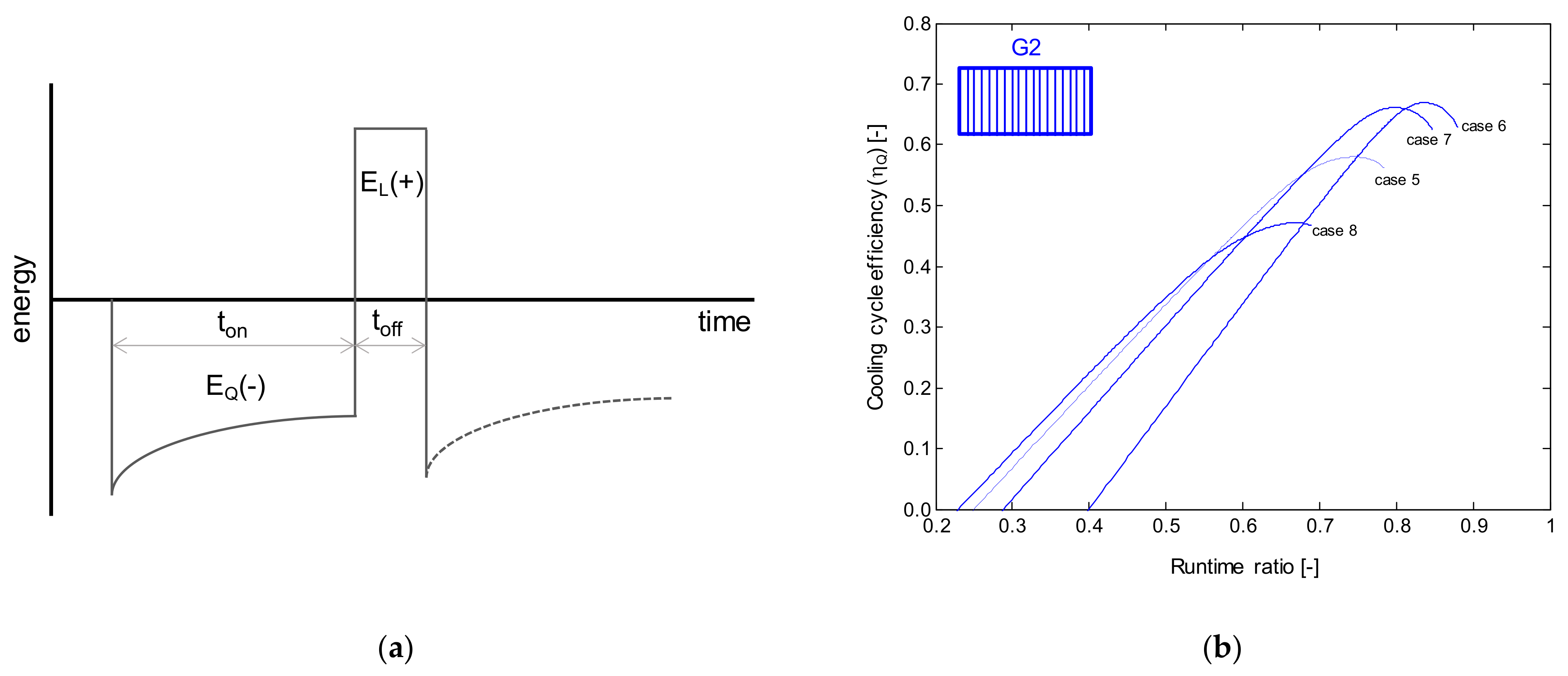
Recently, Da Silva and Hermes [4] assessed the performance of fan-supplied tube-fin evaporators using a mathematical model comprised of a frost formation and defrosting sub-models based on a previous model from Zakrzewski [120]. The cooling cycle efficiency was evaluated as the ratio of the effective amount of heat removed by the evaporator (EQ − EL, as depicted in Figure 14a) to the quantity of heat taken in by the clean evaporator (E0). Therefore, the cooling cycle efficiency ηQ can be expressed as a function of the accumulated mass of frost (Mf), the sensible () and latent () heat transfer rates in the evaporator, as follows:
where isl is the latent heat of solidification, is the clean (initial) evaporator total cooling capacity, ton is the compressor runtime between two defrost operations, and td = Mf isl/ηdẆd is the defrost operation time, where Ẇd the power dissipated by the heater and ηd is the defrost efficiency. This approach allows quantifying the amount of energy released by the defrost system that is not used to melt the frost layer, thus representing a penalty in the thermal loads. Figure 14b shows the cooling cycle efficiency as a function of runtime ratio, ton/(ton + td), for distinct working conditions and fin densities, where optimal runtime ratios can be observed. Moreover, it was noticed that a higher evaporating temperature causes a significant increase in the optimum runtime, which increases the cooling cycle efficiency.
Despite the abundance of literature on commercial and industrial evaporator defrosting, the situation is reversed when it comes to household applications. Some remarkable studies, however, include those by Kim et al. [114] and Bansal et al. [121] for calrod heaters, Knabben et al. [102] and Özkan et al. [122] for distributed aluminum heaters, Melo et al. [123] and Knabben and Melo [124] for distinct technologies, and Malik et al. [125]. Kim et al. [114] conducted a comparative analysis of distinct defrost calrod heaters applied to a side-by-side refrigerator. They investigated the effects of the power capacity, shape, and location of the electrical heaters, reporting a slightly better performance for customized heaters when compared to the traditional ones. In turn, Bansal et al. [121] investigated the performance of a calrod heater used in a vertical freezer. They reported an average defrost efficiency of 32% obtained from a mathematical model based on thermal resistances.
Regarding the performance of aluminum distributed heaters in household appliances, Knabben et al. [102] proposed an in situ study of frosting and defrosting processes in a tube-fin 10-row evaporator using experimental tests and a two-dimensional simulation model, the latter having been previously described. The results show that a significant increase in the defrost efficiency would be reached if the process were carried out by the simultaneous action of two different heaters, with nominal capacities of 175 W and 60 W for the first six rows and the last four rows, respectively. Besides that, it was reported that the gradual reduction in heater power during the defrost process increased efficiency by 118%. Similarly, Ozkan et al. [122] experimentally studied the defrosting process in a two-compartment refrigerator with a distributed aluminum heater. Like Knabben et al. [102], they claimed that the ideal defrosting process should be carried out by using different heaters for each evaporator region.
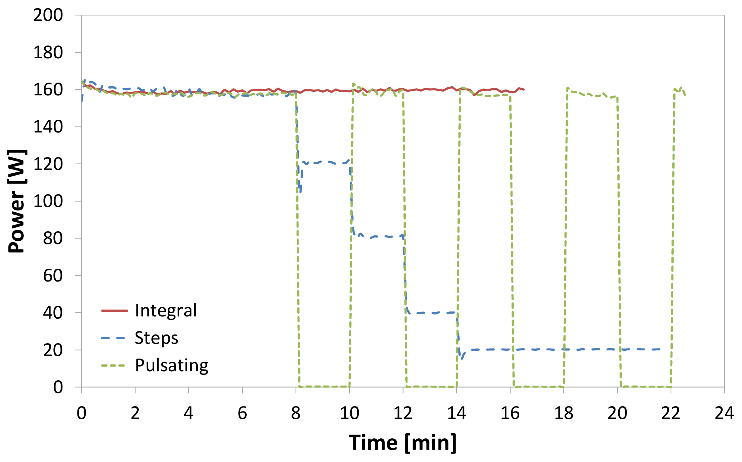
Later, Melo et al. [123] investigated the performance of defrost systems applied to household refrigerators using a purpose-built testing apparatus comprised of a calorimeter, a refrigerated cabinet, and a humidifying system. This approach allowed for an experimental comparison between different defrost systems, maintaining strict control of operating conditions. They evaluated three distinct types of electrical heaters (distributed, calrod, and glass tube) and three actuation modes (integral power, power steps, and pulsating power, as shown in Figure 15) at the same frosting conditions over the evaporator. Table 3 shows the defrost efficiencies related to each defrost system configuration. As can be seen, similar defrost efficiencies were observed for all technologies assessed at the same operating modes, over a range between 27.5% and 48%. Despite the highest efficiency reached by the glass tube at step power mode (48%), Melo et al. [123] stated that the calrod heater seemed to be the most appropriate technology for general use due to its efficiency, low cost, and easy installation.
Despite the considerable number of configurations, the study by Melo et al. [123] only conducted defrosting efficiency tests at the component level. In a complementary investigation, Knabben and Melo [124] evaluated a frost-free refrigerator energy consumption using different combinations of heater technologies and control strategies. This work considered two types of heaters (calrod and distributed) and two power modes (integral and steps). In the integral mode, the power was kept constant at 160 W and the defrosting period of 17.0 min and 19.3 min for the distributed and calrod heaters, respectively. On the other hand, in the steps mode, the power was gradually reduced from 160 W to 20 W, and the defrosting period was set to 28.5 min and 22.3 min for the distributed and calrod heaters, respectively. The calrod heater combined with the steps mode provided the best results, showing 2.6% and 1.7% reductions in the energy consumption and defrost plus recovery time consumption fraction, respectively. Moreover, an energy saving of 4.3% was observed when the combination “calrod heater/integral mode” was replaced by “distributed heater/steps mode.”
According to Knabben and Melo [124], the performance of the calrod heater was lower than that of the distributed heater at the system level. When comparing both technologies operating in the integral mode, the temperature increasing inside the compartments due to defrosting was higher with the calrod heater, first because the calrod heater reaches much higher temperatures than those of the distributed heater, and second because of its design and location regarding the evaporator.
In summary, considering the current challenges of designing low-energy appliances, a defrost strategy must be carefully selected to remove the frost layer from the evaporator as efficiently as possible. To this end, defrosting techniques should be considered in various forms, including passive, active, and system strategies. The defrost strategy is relevant and should be designed to minimize the defrost period and the total power unwantedly expended into the refrigeration cabinet, for example, by optimally distributing the heat along the evaporator coil, detecting the frost layer growth appropriately, or identifying the optimum time to trigger and end the defrost process.
5. Final Remarks
This paper presented the fundamentals and applications of refrigeration systems operations under frosting conditions. The first section showed details of the frost layer nucleation, growth, and densification phenomena. The fundamentals of thermodynamics were then used to quantify the Gibbs-free energy barrier, which must be overcome to trigger the frost nucleation process. Moreover, a frost formation model was described, being able to predict the frost growth process as a function of the surface and psychrometric operating conditions. The key aspects related to the frost thermophysical properties were discussed and the impact that evaporator surface treatments may have on the growth of the frost layer. In its turn, the refrigeration application section showed how the frost formation gradually degrades the evaporator operation and how the fundamentals previously presented can be used to design more efficient evaporators.
Finally, the main aspects related to the defrost operation were presented. A mathematical model regarding the defrost operation was described and used to evaluate the optimal defrost time based on component characteristics and the operating conditions of the refrigeration system. Experimental results, carried out at both the component and system level, were compared using different defrost strategies and highlighted some possibilities to reduce the power consumption of the refrigeration system. In summary, the knowledge gathered in this study has several practical implications to assist the designer in developing cutting-edge technologies for new evaporators, fans, defrost systems, and control strategies.
Although significant advances have been achieved, studies are still needed to discover ways to mitigate the negative effects of frost growth on the surfaces of evaporators. From the industrial application perspective, perhaps most of the attention should be given to the defrost process and the optimization of the evaporator geometry. With respect to the former, electric heaters and different methods such as hot gas bypass and ultrasonic vibration should be investigated deeper. More intelligent frost detection algorithms are a must to optimize the time between defrosting operations. Smart defrosting logics are also important so that the process is interrupted at the proper instant of time. Considering electric heaters, variable power is an interesting option as well. With respect to the evaporator itself, alternative evaporator/fin designs are still a challenge. The use of variable fin spacing along the airflow direction is surely a good way to avoid premature evaporator clogging.
Author Contributions
Conceptualization, C.J.L.H.; writing—original draft preparation, C.J.L.H., J.B., D.L.d.S., F.T.K. and A.D.S.; writing—review and editing, C.J.L.H.; supervision, C.J.L.H. All authors have read and agreed to the published version of the manuscript.
Funding
This work was conducted under the auspices of the National Institutes of Science and Technology (CNPq 404023/2019-3, FAPESC 2019TR0846).
Institutional Review Board Statement
Not applicable.
Informed Consent Statement
Not applicable.
Data Availability Statement
Data analyzed in this work can be found in the references cited in the manuscript.
Conflicts of Interest
The authors declare no conflict of interest.
References
- Bejan, A.; Vargas, J.; Lim, J.S. When to defrost a refrigerator, and when to remove the scale from the heat exchanger of a power plant. Int. J. Heat Mass Transf. 1994, 37, 523–532. [Google Scholar] [CrossRef]
- Dupont, J.L.; Domanski, P.; Lebrum, P.; Ziegler, F. The role of refrigeration in the global economy. In Proceedings of the 38th Informatory Note on Refrigeration Technologies, Paris, France, 1 June 2019. [Google Scholar]
- Borges, B.N.; Melo, C.; Hermes, C.J. Transient simulation of a two-door frost-free refrigerator subjected to periodic door opening and evaporator frosting. Appl. Energy 2015, 147, 386–395. [Google Scholar] [CrossRef]
- Da Silva, D.L.; Hermes, C.J. Optimal defrost cycle for air coolers revisited: A study of fan-supplied tube-fin evaporators. Int. J. Refrig. 2018, 89, 142–148. [Google Scholar] [CrossRef]
- Iragorry, J.; Tao, Y.-X.; Jia, S. Review Article: A Critical Review of Properties and Models for Frost Formation Analysis. HVAC&R Res. 2004, 10, 393–420. [Google Scholar] [CrossRef]
- Song, M.; Dang, C. Review on the measurement and calculation of frost characteristics. Int. J. Heat Mass Transf. 2018, 124, 586–614. [Google Scholar] [CrossRef]
- Lock, G.S.H. The Growth and Decay of Ice; Cambridge University Press: Cambridge, UK, 1990. [Google Scholar]
- Piucco, R.O.; Hermes, C.J.L.; Melo, C.; Barbosa, J.R., Jr. A study of frost nucleation on flat surfaces. Exp. Therm. Flud. Sci. 2008, 32, 1710–1715. [Google Scholar] [CrossRef]
- Becker, R.; Doring, W. Kinetische Behandlung der Keimbildung in übersättigten Dämpfen. Ann. Phys. Lpz. 1935, 24, 719. [Google Scholar] [CrossRef]
- Fletcher, N.H. The Chemical Physics of Ice; Cambridge University Press: Cambridge, UK, 1970. [Google Scholar]
- Volmer, M.; Flood, H. Tropfchenbildung in Dampfen. Z. Phys. Chem. A 1934, 170, 273–285. [Google Scholar] [CrossRef]
- Hermes, C.J.L.; Nascimento, V.S.; Loyola, F.R.; Cardoso, R.P.; Sommers, A.D. A study of frost build-up on hydrophilic and hydrophobic surfaces under forced convection conditions. Exp. Therm. Fluid Sci. 2019, 100, 76–88. [Google Scholar] [CrossRef]
- Wang, Z.-J.; Kwon, D.-J.; deVries, K.L.; Park, J.-M. Frost formation and anti-icing performance of a hydrophobic coating on aluminum. Exp. Therm. Fluid Sci. 2015, 60, 132–137. [Google Scholar] [CrossRef]
- Cai, L.; Wang, R.; Hou, P.; Zhang, X. Study on restraining frost growth at initial stage by hydrophobic coating and hygro-scopic coating. Energy Build. 2011, 43, 1159–1163. [Google Scholar] [CrossRef]
- Liu, Z.; Gou, Y.; Wang, J.; Cheng, S. Frost formation on a super-hydrophobic surface under natural convection conditions. Int. J. Heat Mass Transf. 2008, 51, 5975–5982. [Google Scholar] [CrossRef]
- Na, B.; Webb, R.L. A fundamental understanding of factors affecting frost nucleation. Int. J. Heat Mass Transf. 2003, 46, 3797–3808. [Google Scholar] [CrossRef]
- Hermes, C.J.L.; Piucco, R.O.; Barbosa, J.R., Jr.; Melo, C. A study of frost growth and densification on flat surfaces. Exp. Therm. Fluid Sci. 2009, 33, 371–379. [Google Scholar] [CrossRef]
- Nakaya, U. Snow Crystals: Natural and Artificial; Harvard University Press: Cambridge, MA, USA, 1954. [Google Scholar]
- Libbrecht, K. The physics of snow crystals. Rep. Prog. Phys. 2005, 68, 855–895. [Google Scholar] [CrossRef] [Green Version]
- Kobayashi, T. On the Habit of Snow Crystals Artificially Produced at Low Pressures. J. Meteorol. Soc. Jpn. 1958, 36, 193–208. [Google Scholar] [CrossRef] [Green Version]
- Kobayashi, T. The growth of snow crystals at low supersaturations. Philos. Mag. 1961, 6, 1363–1370. [Google Scholar] [CrossRef]
- Kobayashi, T. On the variation of ice crystal habit with temperature. In Proceedings of the Conference on Physics of Snow and Ice, Sapporo, Japan, 14–19 August 1966. [Google Scholar]
- Magono, C.; Lee, C.W. Meteorological classification of natural snow crystals. J. Fac. Sci. 1966, 2, 321–335. [Google Scholar]
- Kuroda, T.; Lacmann, R. Growth kinetics of ice from the vapour phase and its growth forms. J. Cryst. Growth 1982, 56, 189–205. [Google Scholar] [CrossRef]
- Libbrecht, K.G.; Yu, H. Crystal Growth in the presence of surface melting: Supersaturation dependence of the growth of co-lumnar ice crystals. J. Cryst. Growth 2001, 222, 822–831. [Google Scholar] [CrossRef] [Green Version]
- Hermes, C.J.L.; Sommers, A.D.; Barbosa, J.R., Jr. Time scaling of frost accretion and the square-root-of-time rule. Int. Comm. Heat Mass Transf. 2019, 108, 104281. [Google Scholar] [CrossRef]
- O’Neal, D.L. The Effect of Frost Formation on the Performance of a Parallel Plate Heat Exchanger. Ph.D. Thesis, Purdue University, West Lafayette, IN, USA, 1982. [Google Scholar]
- Wu, X.; Dai, W.; Shan, X.; Wang, W.; Tang, L. Visual and Theoretical Analyses of the Early Stage of Frost Formation on Cold Surfaces. J. Enhanc. Heat Transf. 2007, 14, 257–268. [Google Scholar] [CrossRef]
- Brian, P.L.T.; Reid, R.C.; Brazinsky, L. Cryogenic frost properties. Cryog. Technol. 1969, 5, 205–212. [Google Scholar]
- Schneider, H. Equation of the growth rate of frost forming on cooled surfaces. Int. J. Heat Mass Transf. 1978, 21, 1019–1024. [Google Scholar] [CrossRef]
- Sanders, C.T.H. The Influence of Frost Formation and Defrosting on the Performance of Air Coolers. Ph.D. Thesis, Technische Hogeschool, Delft, The Netherlands, 1974. [Google Scholar]
- Sami, S.M.; Duong, T. Numerical prediction of frost formation on cooled beat exchangers. Int. Comm. Heat Mass Transf. 1988, 15, 81–84. [Google Scholar] [CrossRef]
- Yonko, J.D.; Sepsy, C.F. An investigation of the thermal conductivity of frost while forming on a horizontal plate. ASHRAE Trans. 1967, 73, 1. [Google Scholar]
- Sherif, S.; Raju, S.; Padki, M.; Chan, A. A semi-empirical transient method for modelling frost formation on a flat plate. Int. J. Refrig. 1993, 16, 321–329. [Google Scholar] [CrossRef]
- Hayashi, Y.; Aoki, A.; Adachi, S.; Hori, K. Study of Frost Properties Correlating with Frost Formation Types. J. Heat Transf. 1977, 99, 239–245. [Google Scholar] [CrossRef]
- Tao, Y.X.; Besant, R.W.; Mao, Y. Characteristics of frost growth on a flat plate during the early growth period. ASHRAE Trans. 1993, 93, 746–753. [Google Scholar]
- Le Gall, R.; Grillot, J.M. Modelling of frost growth and densification. Int. J. Heat Mass Transf. 1997, 40, 3177–3187. [Google Scholar] [CrossRef]
- Auracher, H. Effective Thermal Conductivity of Frost. In Proceedings of the International Symposium on Heat and Mass Transfer in Refrigeration and Cryogenics, Dubrovnik, Croatia, 1–5 September 1986. [Google Scholar]
- Lee, K.-S.; Kim, W.-S.; Lee, T.-H. A one-dimensional model for frost formation on a cold flat surface. Int. J. Heat Mass Transf. 1997, 40, 4359–4365. [Google Scholar] [CrossRef]
- Ismail, K.; Salinas, C. Modeling of frost formation over parallel cold plates. Int. J. Refrig. 1999, 22, 425–441. [Google Scholar] [CrossRef]
- Mao, Y.; Besant, R.W.; Rezkallah, K.S. Measurement and correlations of frost properties with airflow over a flat plate. ASHRAE Trans. 1992, 98, 65–77. [Google Scholar]
- Lüer, A.; Beer, H. Frost deposition in a parallel plate channel under laminar flow conditions. Int. J. Therm. Sci. 2000, 39, 85–95. [Google Scholar] [CrossRef]
- Cheng, C.-H.; Cheng, Y.-C. Predictions of frost growth on a cold plate in atmospheric air. Int. Commun. Heat Mass Transf. 2001, 28, 953–962. [Google Scholar] [CrossRef]
- Yang, D.-K.; Lee, K.-S. Dimensionless correlations of frost properties on a cold plate. Int. J. Refrig. 2004, 27, 89–96. [Google Scholar] [CrossRef]
- Na, B.; Webb, R.L. New model for frost growth rate. Int. J. Heat Mass Transf. 2004, 47, 925–936. [Google Scholar] [CrossRef]
- Lee, Y.; Ro, S. Analysis of the frost growth on a flat plate by simple models of saturation and supersaturation. Exp. Therm. Fluid Sci. 2005, 29, 685–696. [Google Scholar] [CrossRef]
- Kandula, M. Frost growth and densification in laminar flow over flat surfaces. Int. J. Heat Mass Transf. 2011, 54, 3719–3731. [Google Scholar] [CrossRef]
- Hermes, C.J. An analytical solution to the problem of frost growth and densification on flat surfaces. Int. J. Heat Mass Transf. 2012, 55, 7346–7351. [Google Scholar] [CrossRef]
- Loyola, F.R.; Nascimento, V.S.; Hermes, C.J. Modeling of frost build-up on parallel-plate channels under supersaturated air-frost interface conditions. Int. J. Heat Mass Transf. 2014, 79, 790–795. [Google Scholar] [CrossRef]
- Nascimento, V.S.; Loyola, F.R.; Hermes, C.J. A study of frost build-up on parallel plate channels. Exp. Therm. Fluid Sci. 2015, 60, 328–336. [Google Scholar] [CrossRef]
- El Cheikh, A.; Jacobi, A. A mathematical model for frost growth and densification on flat surfaces. Int. J. Heat Mass Transf. 2014, 77, 604–611. [Google Scholar] [CrossRef]
- O’Neal, D.L.; Tree, D.L. Measurements of frost growth and density in a parallel plate geometry. ASHRAE Trans. 1984, 90, 278–290. [Google Scholar]
- Hermes, C.J.; Sommers, A.D.; Gebhart, C.W.; Nascimento, V.S. A semi-empirical model for predicting frost accretion on hydrophilic and hydrophobic surfaces. Int. J. Refrig. 2018, 87, 164–171. [Google Scholar] [CrossRef]
- Sommers, A.D.; Napora, A.C.; Truster, N.L.; Caraballo, E.J.; Hermes, C.J. A semi-empirical correlation for predicting the frost density on hydrophilic and hydrophobic substrates. Int. J. Refrig. 2017, 74, 313–323. [Google Scholar] [CrossRef]
- Baehr, H.D.; Stephan, K. Heat and Mass Transfer, 2nd ed.; Springer: Berlin, Germany, 2006. [Google Scholar]
- Na, B.; Webb, R.L. Mass transfer on and within a frost layer. Int. J. Heat Mass Trans. 2004, 47, 899–911. [Google Scholar] [CrossRef]
- Negrelli, S.; Hermes, C.J. A semi-empirical correlation for the thermal conductivity of frost. Int. J. Refrig. 2015, 58, 243–252. [Google Scholar] [CrossRef]
- Negrelli, S.; Cardoso, R.P.; Hermes, C.J. A finite-volume diffusion-limited aggregation model for predicting the effective thermal conductivity of frost. Int. J. Heat Mass Transf. 2016, 101, 1263–1272. [Google Scholar] [CrossRef]
- Negrelli, S.; Nascimento, V.S.; Hermes, C.J. A study of the effective thermal conductivity of frost formed on parallel plate channels. Exp. Therm. Fluid Sci. 2016, 78, 301–308. [Google Scholar] [CrossRef]
- Hosseini, S.H.; Valizadeh, M.; Zendehboudi, A.; Song, M. General correlation for frost thermal conductivity on parallel sur-face channels. Energy Build. 2020, 225, 110282. [Google Scholar] [CrossRef]
- Hermes, C.J.; Loyola, F.R.; Nascimento, V.S. A semi-empirical correlation for the frost density. Int. J. Refrig. 2014, 46, 100–104. [Google Scholar] [CrossRef]
- Kim, M.-H.; Kim, H.; Lee, K.-S.; Kim, D.R. Frosting characteristics on hydrophobic and superhydrophobic surfaces: A review. Energy Convers. Manag. 2017, 138, 1–11. [Google Scholar] [CrossRef]
- Kim, K.; Lee, K.-S. Frosting and defrosting characteristics of a fin according to surface contact angle. Int. J. Heat Mass Transf. 2011, 54, 2758–2764. [Google Scholar] [CrossRef]
- Antonini, C.; Innocenti, M.; Horn, T.; Marengo, M.; Amirfazli, A. Understanding the effect of superhydrophobic coatings on energy reduction in anti-icing systems. Cold Reg. Sci. Technol. 2011, 67, 58–67. [Google Scholar] [CrossRef]
- Rahimi, M.; Afshari, A.; Fojan, P.; Gurevich, L. The effect of surface modification on initial ice formation on aluminum sur-faces. Appl. Surf. Sci. 2015, 355, 327–333. [Google Scholar] [CrossRef]
- Rahman, M.A.; Jacobi, A.M. Effects of microgroove geometry on the early stages of frost formation and frost properties. Appl. Therm. Eng. 2015, 56, 91–100. [Google Scholar] [CrossRef]
- Yang, W.; Zeng, B.; Zhang, Y.; He, S.; Zhao, X. Frosting performance of a nanoporous hydrophilic aluminium surface. Energies 2018, 11, 3483. [Google Scholar] [CrossRef] [Green Version]
- Mahvi, A.J.; Boyna, K.; Musser, A.; Elbel, S.; Miljkovic, N. Superhydrophobic heat exchangers delay frost formation and enhance efficiency of electric vehicle heat pumps. Int. J. Heat Mass Transf. 2021, 172, 121162. [Google Scholar] [CrossRef]
- Bergman, T.L.; Lavine, A.S.; Incropera, F.P.; DeWitt, D.P. Fundamentals of Heat and Mass Transfer, 7th ed.; John Wiley & Sons: Hoboken, NJ, USA, 2011. [Google Scholar]
- Chatterjee, A.; Derby, M.M.; Peles, Y.; Jensen, M.K. Enhancement of condensation heat transfer with patterned surfaces. Int. J. Heat Mass Transf. 2014, 71, 675–681. [Google Scholar] [CrossRef] [Green Version]
- Seo, D.; Lee, C.; Nam, Y. Influence of geometric patterns of microstructured superhydrophobic surfaces on water-harvesting performance dewing. Langmuir 2014, 30, 15468–15476. [Google Scholar] [CrossRef]
- Peng, B.; Ma, X.; Lan, Z.; Xu, W.; Wen, R. Experimental investigation on steam condensation heat transfer enhancement with vertically patterned hydrophobic-hydrophilic hybrid surfaces. Int. J. Heat Mass Transf. 2015, 83, 27–38. [Google Scholar] [CrossRef]
- Alwazzan, M.; Egab, K.; Peng, B.; Khan, J.; Li, C. Condensation on hybrid-patterned copper tubes (I): Characterization of con-densation heat transfer. Int. J. Heat Mass Transf. 2017, 112, 991–1004. [Google Scholar] [CrossRef]
- Sommers, A.D.; Brest, T.J.; Eid, K.F. Topography-Based Surface Tension Gradients to Facilitate Water Droplet Movement on Laser-Etched Copper Substrates. Langmuir 2013, 29, 12043–12050. [Google Scholar] [CrossRef] [PubMed]
- Liu, C.; Sun, J.; Li, J.; Xiang, C.; Chenghao, X.; Wang, Z.; Zhou, X. Long-range spontaneous droplet self-propulsion on wettability gradient surfaces. Sci. Rep. 2017, 7, 1–8. [Google Scholar] [CrossRef]
- Sommers, A.D.; Panth, M.; Eid, K.F. Self-propelled water droplet movement on a laser-etched radial gradient copper surface. Appl. Therm. Eng. 2020, 173, 115226. [Google Scholar] [CrossRef]
- Storey, B.; Jacobi, A. The effect of streamwise vortices on the frost growth rate in developing laminar channel flows. Int. J. Heat Mass Transf. 1999, 42, 3787–3802. [Google Scholar] [CrossRef]
- Sommers, A.; Jacobi, A. Air-side heat transfer enhancement of a refrigerator evaporator using vortex generation. Int. J. Refrig. 2005, 28, 1006–1017. [Google Scholar] [CrossRef]
- Stoecker, W.F. How frost formation on coils affects refrigeration systems. Refrig. Eng. 1957, 65, 42–46. [Google Scholar]
- Da Silva, D.L.; Hermes, C.J.; Melo, C. Experimental study of frost accumulation on fan-supplied tube-fin evaporators. Appl. Therm. Eng. 2011, 31, 1013–1020. [Google Scholar] [CrossRef] [Green Version]
- Kondepudi, S.N.; O’Neal, D.L. The effect of frost growth on extended surface heat exchanger performance: A review. ASHRAE Trans. 1987, 93, 258–274. [Google Scholar]
- Rite, R.W.; Crawford, R.R. The effect of frost accumulation on the performance of domestic refrigerator-freezer finned-tube evaporator coils. ASHRAE Trans. 1991, 97, 428–437. [Google Scholar]
- Ogawa, K.; Tanaka, N.; Takeshita, M. Performance improvement of plate fin-and-tube heat exchangers under frosting condi-tions. ASHRAE Trans. 1993, 99, 762–771. [Google Scholar]
- Carlson, D.M.; Hrnjak, P.S.; Bullard, C.W. Deposition, Distribution, and Effects of Frost on a Multi-Row Heat Exchanger Performance; Technical Report; University of Illinois at Urbana-Champaign: Champaign, IL, USA, 2001. [Google Scholar]
- Jhee, S.; Lee, K.-S.; Kim, W.-S. Effect of surface treatments on the frosting/defrosting behavior of a fin-tube heat exchanger. Int. J. Refrig. 2002, 25, 1047–1053. [Google Scholar] [CrossRef]
- Inan, C.; Karatas, H.; Egrican, N.; Lale, C. Real time upright freezer evaporator performance under frosted conditions. In Proceedings of the International Refrigeration and Air Conditioning Conference at Purdue, West Lafayette, IN, USA, 16–19 July 2002. [Google Scholar]
- Deng, D.-Q.; Xu, L.; Xu, S.-Q. Experimental investigation on the performance of air cooler under frosting conditions. Appl. Therm. Eng. 2003, 23, 905–912. [Google Scholar] [CrossRef]
- Chen, H.; Thomas, L.; Besant, R.W. Fan supplied heat exchanger fin performance under frosting conditions. Int. J. Refrig. 2002, 26, 140–149. [Google Scholar] [CrossRef]
- Seker, D.; Karatas, H.; Egrican, N. Frost formation on fin-and-tube heat exchangers. Part I—Modeling of frost formation on fin-and-tube heat exchangers. Int. J. Refrig. 2004, 27, 367–374. [Google Scholar] [CrossRef]
- Liu, Z.; Zhu, H.; Wang, H. Study on Transient Distributed Model of Frost on Heat Pump Evaporator. J. Asian Arch. Build. Eng. 2005, 4, 265–270. [Google Scholar] [CrossRef] [Green Version]
- Tso, C.; Cheng, Y.; Lai, A.; Lai, C.K.A. Dynamic behavior of a direct expansion evaporator under frosting condition. Part, I. Distributed model. Int. J. Refrig. 2006, 29, 611–623. [Google Scholar] [CrossRef]
- Xia, Y.; Zhong, Y.; Hrnjak, P.; Jacobi, A. Frost, defrost, and refrost and its impact on the air-side thermal-hydraulic performance of louvered-fin, flat-tube heat exchangers. Int. J. Refrig. 2006, 29, 1066–1079. [Google Scholar] [CrossRef]
- Aljuwayhel, N.F. Numerical and Experimental Study of the Influence of Frost Formation and Defrosting on the Performance of Industrial Evaporator Coils. Ph.D. Thesis, University of Wisconsin-Madison, Madison, WI, USA, 2006. [Google Scholar]
- Yang, D.-K.; Lee, K.-S.; Song, S. Fin spacing optimization of a fin-tube heat exchanger under frosting conditions. Int. J. Heat Mass Transf. 2006, 49, 2619–2625. [Google Scholar] [CrossRef]
- Özkan, D.B.; Ozil, E. Experimental study on the effect of frost parameters on domestic refrigerator finned tube evaporator coils. Appl. Therm. Eng. 2006, 26, 2490–2493. [Google Scholar] [CrossRef]
- Ngonda, T.N.; Sheer, T.J. Frost formation on cooling coil in supersaturated supply air. In Proceedings of the International Con-gress of Refrigeration, Beijing, China, 21–26 August 2007. [Google Scholar]
- Albert, M.; Sahinagic, R.; Gasser, L.; Wellig, B.; Hilfiker, K. Prediction of ice and frost formation in the fin tube evaporators for air/water heat pumps. In Proceedings of the 9th IEA Heat Pump Conference, Zurich, Switzerland, 20–22 May 2008. [Google Scholar]
- Huang, J.M.; Hsieh, W.C.; Ke, X.J.; Wang, C.C. The effects of frost thickness on the heat transfer of finned tube heat ex-changer subject to the combined influence of fan types. Appl. Therm. Eng. 2008, 28, 728–737. [Google Scholar] [CrossRef]
- Zhang, P.; Hrnjak, P. Air-side performance evaluation of three types of heat exchangers in dry, wet and periodic frosting conditions. Int. J. Refrig. 2009, 32, 911–921. [Google Scholar] [CrossRef] [Green Version]
- Lenic, K.; Trp, A.; Frankovic, B. Prediction of an effective cooling output of the fin-and-tube heat exchanger under frosting conditions. Appl. Therm. Eng. 2009, 29, 2534–2543. [Google Scholar] [CrossRef]
- Moallem, E.; Cremaschi, L.; Fischer, D.E. Experimental investigation of frost growth on microchannel heat exchangers. In Proceedings of the 13th International Refrigeration and Air Conditioning Conference at Purdue, West Lafayette, IN, USA, 12–15 August 2010. [Google Scholar]
- Knabben, F.T.; Hermes, C.J.; Melo, C. In-situ study of frosting and defrosting processes in tube-fin evaporators of household refrigerating appliances. Int. J. Refrig. 2011, 34, 2031–2041. [Google Scholar] [CrossRef]
- Da Silva, D.L.; Hermes, C.J.; Melo, C. First-principles modeling of frost accumulation on fan-supplied tube-fin evaporators. Appl. Therm. Eng. 2011, 31, 2616–2621. [Google Scholar] [CrossRef]
- Wu, J.; Ouyang, G.; Hou, P.; Xiao, H. Experimental investigation of frost formation on a parallel flow evaporator. Appl. Energy 2011, 88, 1549–1556. [Google Scholar] [CrossRef]
- Jopollo, C.M.; Molinaroli, L.; Antonellis, S.D.; Merlo, U. Experimental analysis of frost formation with presence of an electric field on fin and tube evaporator. Int. J. Refrig. 2012, 35, 468–474. [Google Scholar] [CrossRef]
- Kim, K.; Kim, D.R.; Lee, K.-S. Local frosting behavior of a plated-fin and tube heat exchanger according to the refrigerant flow direction and surface treatment. Int. J. Heat Mass Transf. 2013, 64, 751–758. [Google Scholar] [CrossRef]
- Ribeiro, R.S.; Hermes, C.J. Algebraic modeling and thermodynamic design of fan-supplied tube-fin evaporators running under frosting conditions. Appl. Therm. Eng. 2014, 70, 552–559. [Google Scholar] [CrossRef]
- Da Silva, D.L.; Melo, C.; Hermes, C.J. Effect of frost morphology on the thermal-hydraulic performance of fan-supplied tube-fin evaporators. Appl. Therm. Eng. 2017, 111, 1060–1068. [Google Scholar] [CrossRef]
- Timmermann, M.A.S.; Kaviany, M.; Barbosa, J.R., Jr. Thermal performance of peripheral-finned tube evaporators under frost-ing. Int. J. Heat Mass Trans. 2018, 116, 194–207. [Google Scholar] [CrossRef]
- Popovac, M.; Seichter, S.; Benovsky, P.; Fleckl, T.; Reichl, C. Numerical analysis of the frosting performance of the air side of a heat pump. In Proceedings of the 24th International Congress of Refrigeration, Yokohama, Japan, 16–22 August 2015. [Google Scholar]
- Amer, M.; Wang, C.-C. Experimental investigation on defrosting of a cold flat plate via ultrasonic vibration under natural convection. Appl. Therm. Eng. 2020, 179, 115729. [Google Scholar] [CrossRef]
- Amer, M.; Wang, C.-C. Review of defrosting methods. Renew. Sustain. Energy Rev. 2017, 73, 53–74. [Google Scholar] [CrossRef]
- Dong, J.; Deng, S.S.; Jiang, Y.; Xia, L.; Yao, Y. An experimental study on defrosting heat supplies and energy consumptions during a reverse cycle defrost operation for an air source heat pump. Appl. Therm. Eng. 2012, 37, 380–387. [Google Scholar] [CrossRef]
- Kim, Y.-S.; Tikhonov, A.N.; Shin, Y.; Lee, J. Experimental study on high performance defrosting heater for household refrigerator. In Proceedings of the 13th International Heat Transfer Conference, Sydney, Australia, 13–18 August 2006. [Google Scholar]
- Stoecker, W. Selecting the size of pipes carrying hot gas to defrost evaporators. Int. J. Refrig. 1984, 7, 225–228. [Google Scholar] [CrossRef]
- Niederer, D.H. Frosting and defrosting effects on coil heat transfer. ASHRAE Trans. 1986, 82, 467–473. [Google Scholar]
- Cho, H.; Kim, Y.; Jang, I. Performance of a showcase refrigeration system with multi-evaporator during on–off cycling and hot-gas bypass defrost. Energy 2005, 30, 1915–1930. [Google Scholar] [CrossRef]
- Byun, J.-S.; Lee, J.; Jeon, C.-D. Frost retardation of an air-source heat pump by the hot gas bypass method. Int. J. Refrig. 2008, 31, 328–334. [Google Scholar] [CrossRef]
- Minglu, Q.; Liang, X.; Deng, S.; Yiqiang, J. Improved indoor thermal comfort during defrost with a novel reverse-cycle de-frosting method for air source heat pumps. Build. Environ. 2010, 45, 2354–2361. [Google Scholar] [CrossRef]
- Zakrzewski, B. Optimal defrost cycle for the air cooler. Int. J. Refrig. 1984, 7, 41–45. [Google Scholar] [CrossRef]
- Bansal, P.; Fothergill, D.; Fernandes, R. Thermal analysis of the defrost cycle in a domestic freezer. Int. J. Refrig. 2010, 33, 589–599. [Google Scholar] [CrossRef]
- Özkan, D.B.; Ozil, E.; Inan, C. Experimental Investigation of the Defrosting Process on Domestic Refrigerator Finned Tube Evaporators. Heat Transf. Eng. 2012, 33, 548–557. [Google Scholar] [CrossRef]
- Melo, C.; Knabben, F.T.; Pereira, P.V. An experimental study on defrost heaters applied to frost-free household refrigerators. Appl. Therm. Eng. 2013, 51, 239–245. [Google Scholar] [CrossRef]
- Knabben, F.T.; Melo, C. An experimental study on the effect of a new defrosting strategy on the energy consumption of household refrigerator. In Proceedings of the 16th International Refrigeration and Air Conditioning Conference at Purdue, West Lafayette, IN, USA, 11–14 July 2016. [Google Scholar]
- Malik, A.N.; Khan, S.A.; Lazoglu, I. A novel hybrid frost detection and defrosting system for domestic refrigerators. Int. J. Refrig. 2020, 117, 256–268. [Google Scholar] [CrossRef]
Figure 1.
The number of research papers with terms related to ‘‘frost” or “defrost,” and ‘‘heat exchanger” or ‘‘evaporator” published in engineering journals for the last two decades (www.sciencedirect.com, 23 January 2021).
Figure 1.
The number of research papers with terms related to ‘‘frost” or “defrost,” and ‘‘heat exchanger” or ‘‘evaporator” published in engineering journals for the last two decades (www.sciencedirect.com, 23 January 2021).
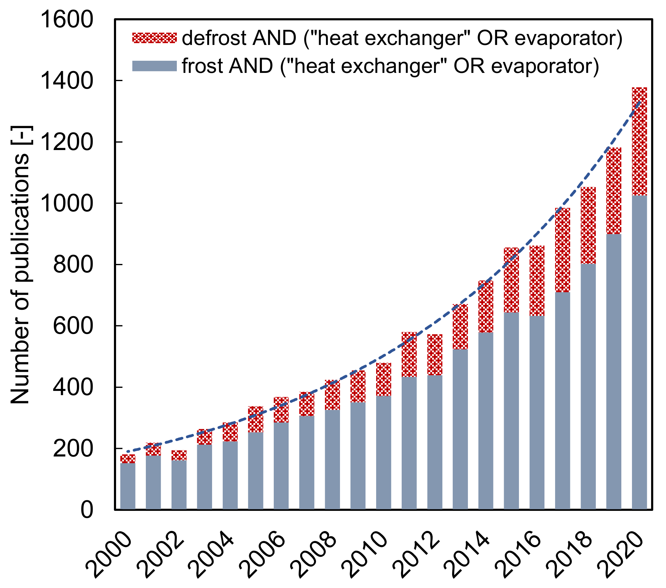
Figure 2.
Phase diagram of water as a function of temperature and pressure.
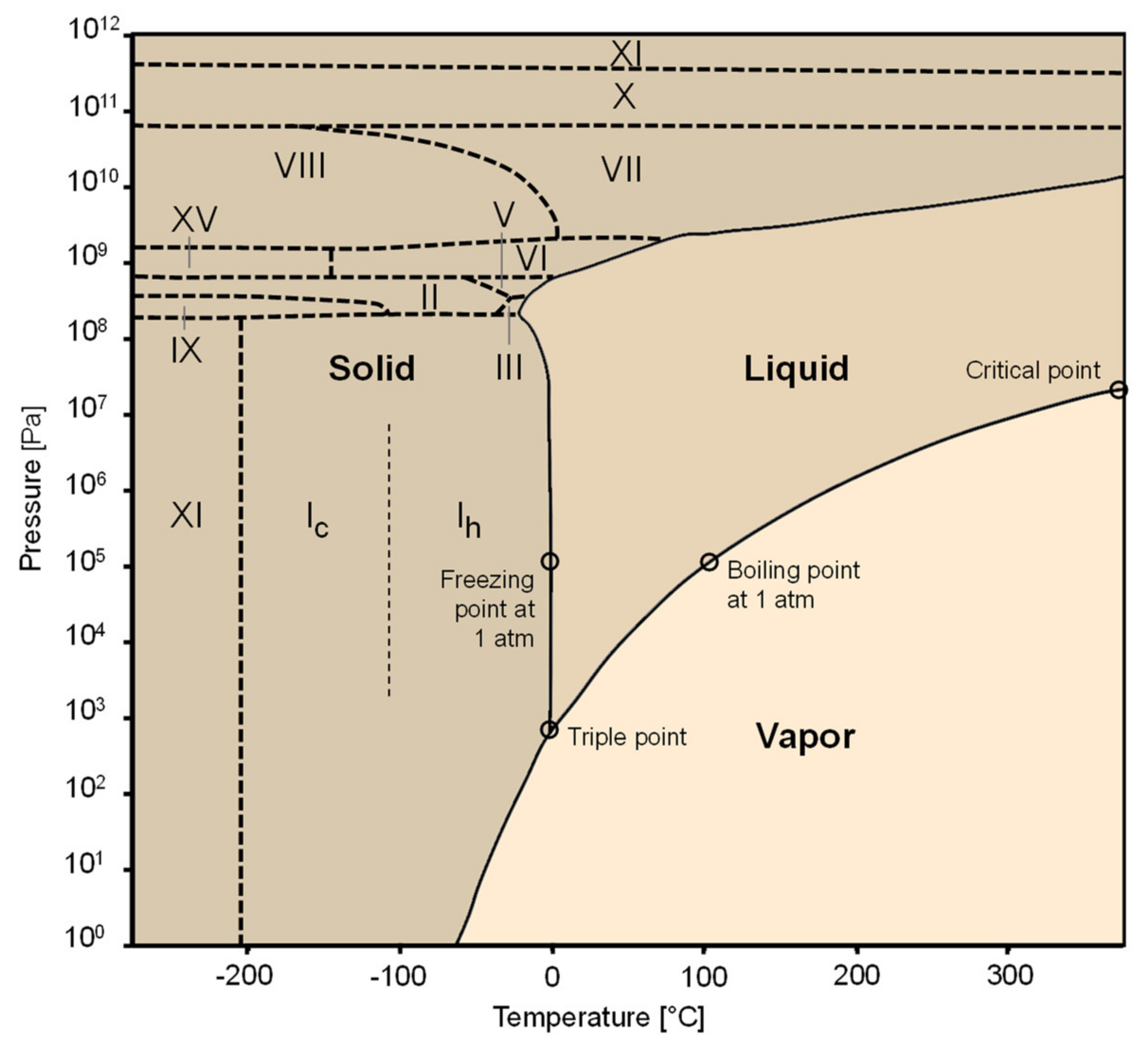
Figure 3.
Phase transition of water for different psychrometric and surface conditions.

Figure 4.
Representation of the metastable states during vapor desublimation on a psychrometric chart.
Figure 4.
Representation of the metastable states during vapor desublimation on a psychrometric chart.
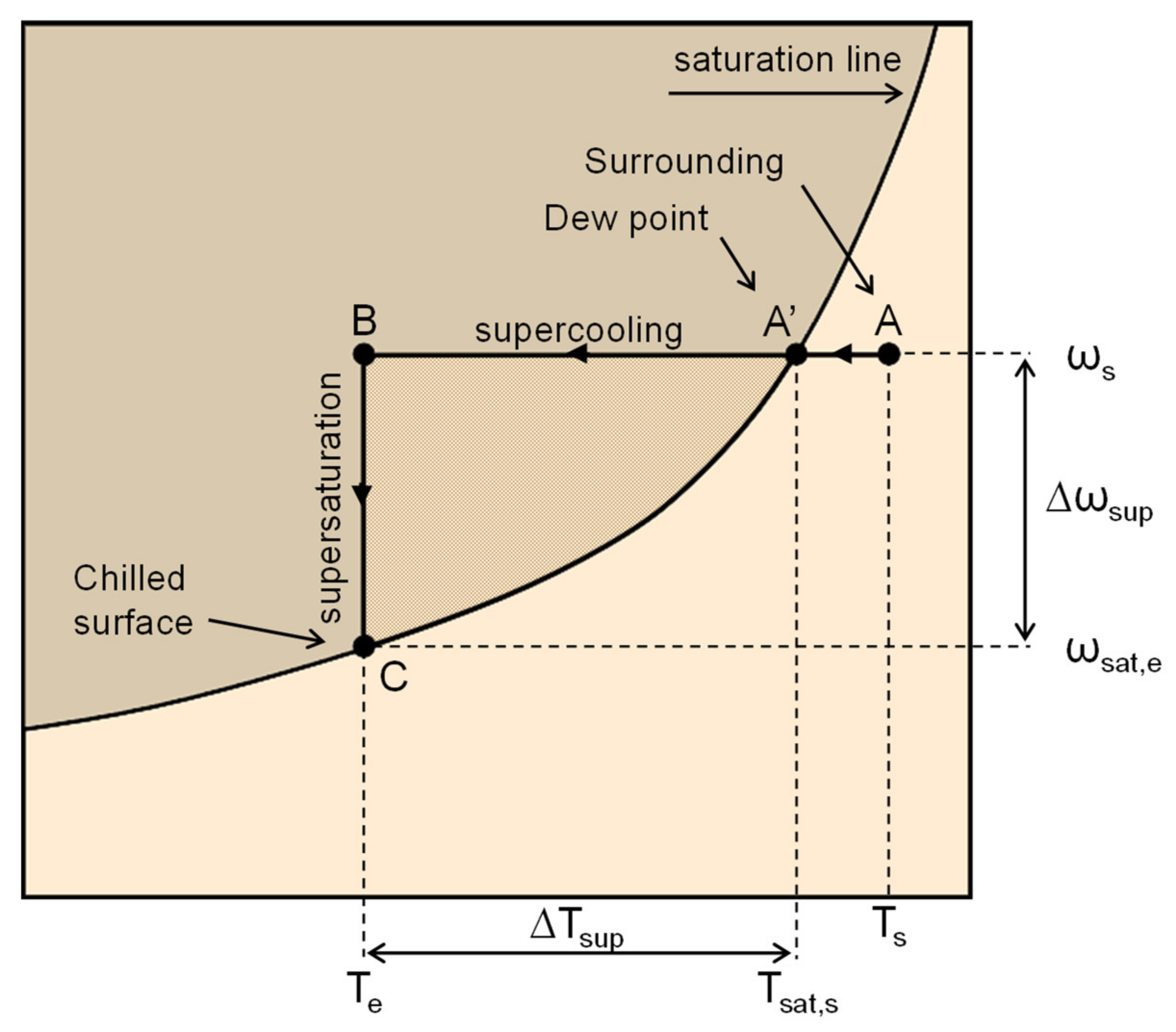
Figure 5.
Schematic representation of embryo growth during heterogeneous nucleation on a hydrophilic surface.
Figure 5.
Schematic representation of embryo growth during heterogeneous nucleation on a hydrophilic surface.
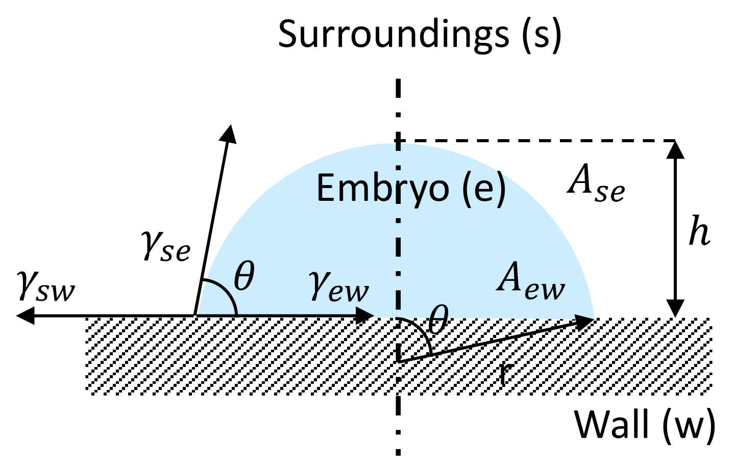
Figure 6.
Minimum supercooling degree for the onset of nucleation on a smooth surface as a function of the contact angle.
Figure 6.
Minimum supercooling degree for the onset of nucleation on a smooth surface as a function of the contact angle.
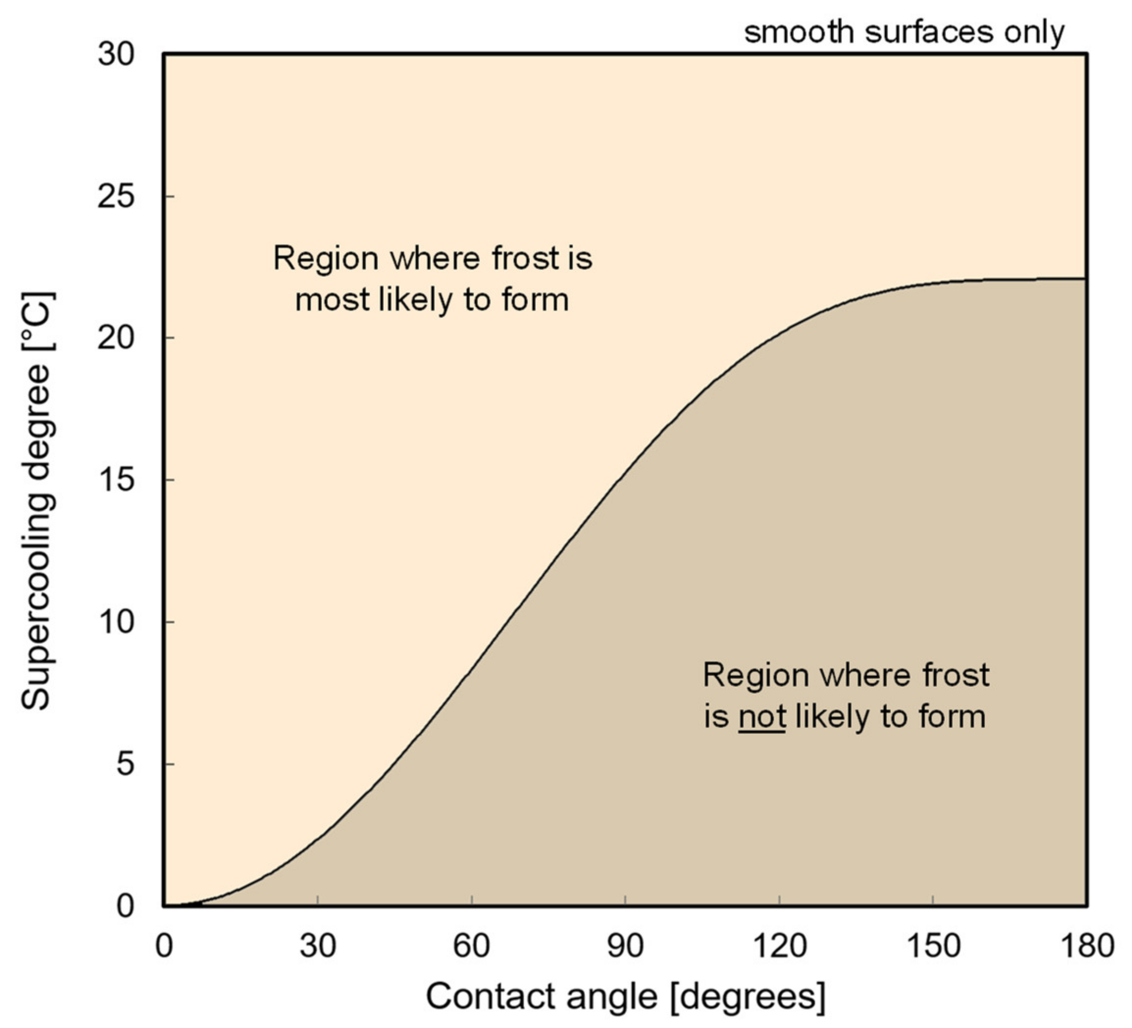
Figure 7.
Schematic representation of the early crystal growth processes.

Figure 8.
Kobayashi’s frost morphology map.
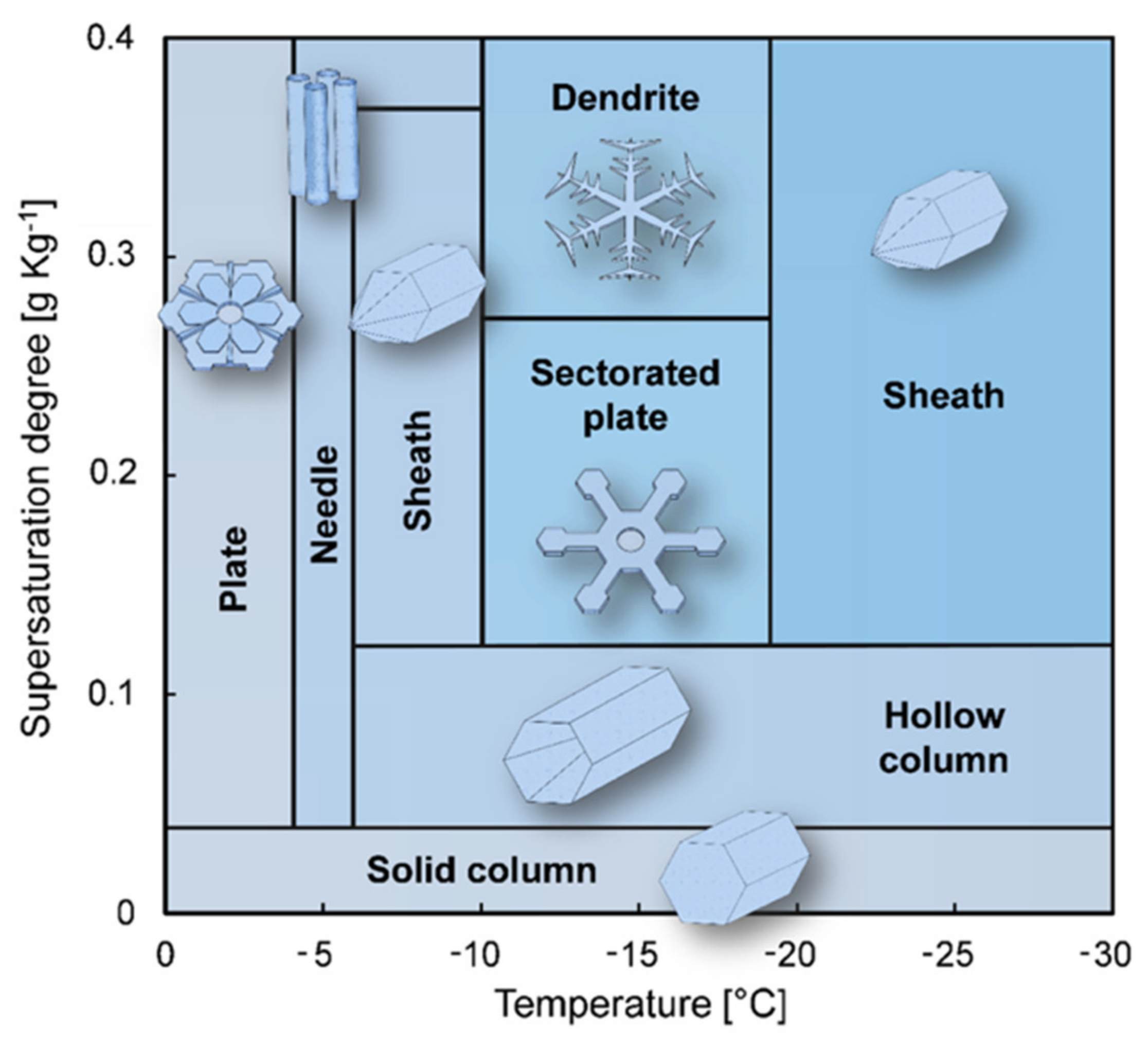
Figure 9.
Schematic of the growth and densification of a frosted medium.
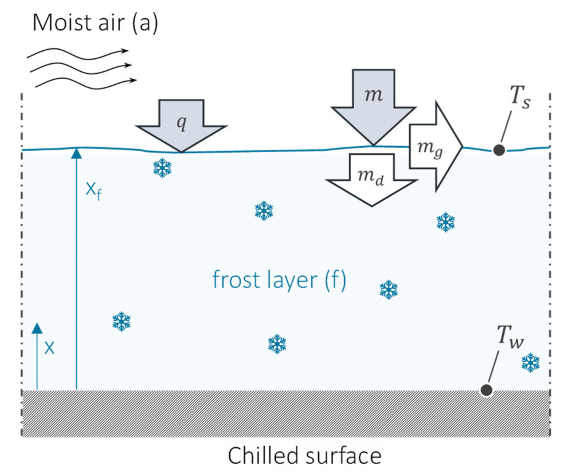
Figure 10.
Snapshots of the frost formation process as a function of time for an airstream velocity of 0.7 m/s, air temperature of 16 °C, relative humidity of 50%, and a plate temperature of −18 °C [8].
Figure 10.
Snapshots of the frost formation process as a function of time for an airstream velocity of 0.7 m/s, air temperature of 16 °C, relative humidity of 50%, and a plate temperature of −18 °C [8].
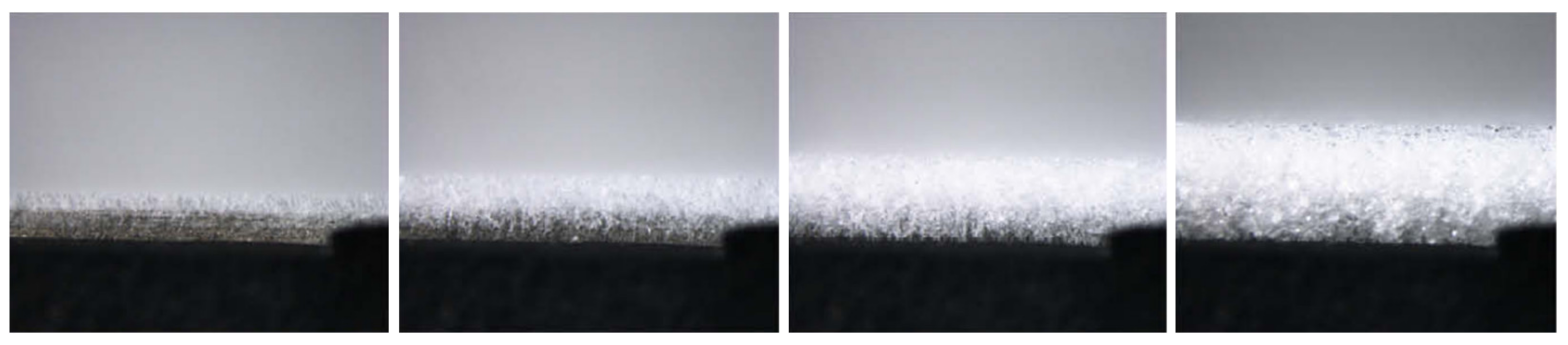
Figure 11.
Sample of a porous medium constructed using the diffusion-limited aggregation technique [58].
Figure 11.
Sample of a porous medium constructed using the diffusion-limited aggregation technique [58].
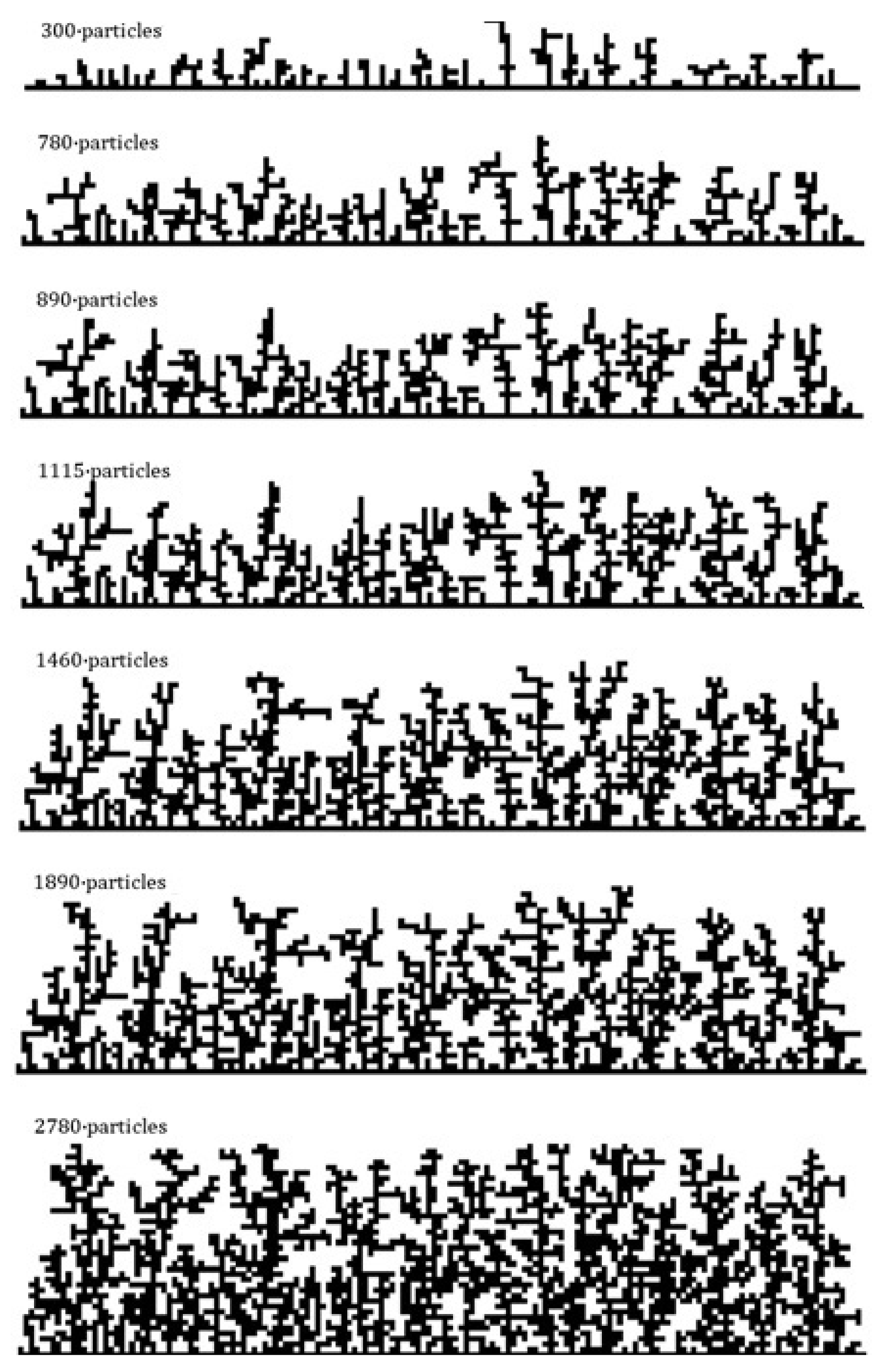
Figure 12.
Two-dimensional frost accumulation over an evaporator coil: visualization (a), and simulation results (b) [102].
Figure 12.
Two-dimensional frost accumulation over an evaporator coil: visualization (a), and simulation results (b) [102].

Figure 13.
Visualizations of distinct frost layer morphologies (a), and their effect on the airside pressure drop (b) [80].
Figure 13.
Visualizations of distinct frost layer morphologies (a), and their effect on the airside pressure drop (b) [80].

Figure 14.
Representation of the cooling and defrost cycles (a), and the so-called cooling cycle efficiency as a function of the compressor runtime ratio (b) [4].
Figure 14.
Representation of the cooling and defrost cycles (a), and the so-called cooling cycle efficiency as a function of the compressor runtime ratio (b) [4].

Figure 15.
Different actuation modes for defrosting by means of electric heaters [124].
Figure 15.
Different actuation modes for defrosting by means of electric heaters [124].

Table 1.
Selected works on modeling of frost growth and densification processes.
| Author | Year | Origin | Porous Medium | Geometry | Density | Thermal Conductivity | Air-Frost Interface |
|---|---|---|---|---|---|---|---|
| Brian et al. [29] | 1969 | USA | No | Flat plate | Their own | Various | Saturated |
| Schneider [30] | 1978 | Germany | No | Flat plate | Their own | Their own | Saturated |
| O’Neal [27] | 1982 | USA | Yes | Channel | Prescribed | Sanders [31] | Saturated |
| Sami and Duong [32] | 1988 | Canada | Yes | Flat plate | - | Yonko and Sepsy [33] | Saturated |
| Sherif et al. [34] | 1993 | USA | Yes | Flat plate | Hayashi et al. [35] | Various | Saturated |
| Tao et al. [36] | 1993 | Canada | No | Flat plate | Prescribed | Their own | Saturated |
| Le gall et al. [37] | 1997 | France | Yes | Flat plate | Prescribed | Auracher [38] | Saturated |
| Lee et al. [39] | 1997 | S. Korea | No | Flat plate | - | Their own | Saturated |
| Ismael and Salinas [40] | 1999 | Brazil | Yes | Channel | Mao et al. [41] | Yonko and Sepsy [33] | Saturated |
| Lüer and Beer [42] | 2000 | Germany | Yes | Channel | Various | Auracher [38] | Saturated |
| Cheng and Cheng [43] | 2001 | China | No | Flat plate | Hayashi et al. [35] | Brian et al. [29] | Saturated |
| Yang and Lee [44] | 2004 | S. Korea | No | Flat plate | Their own | Their own | Saturated |
| Na and Webb [45] | 2004 | USA | Yes | Flat plate | Prescribed | Sanders [31] | Supersaturated |
| Lee and Ro [46] | 2005 | S. Korea | Yes | Flat plate | Prescribed | Auracher [38] | Supersaturated |
| Hermes et al. [17] | 2009 | Brazil | Yes | Flat plate | Their own | Lee et al. [39] | Saturated |
| Cai et al. [14] | 2011 | USA | Yes | Flat plate | Their own | Their own | Saturated |
| Kandula [47] | 2011 | USA | Yes | Flat plate | His own | His own | Saturated |
| Hermes [48] | 2012 | Brazil | Yes | Flat plate | His own | His own | Saturated |
| Loyola et al. [49] | 2014 | Brazil | Yes | Channel | Nascimento et al. [50] | Hermes [48] | Supersaturated |
| El Cheikh and Jacobi [51] | 2014 | USA | Yes | Flat plate | Prescribed | O’Neal and Tree [52] | Supersaturated |
| Hermes et al. [53] | 2018 | USA/Brazil | No | Flat plate | Sommers et al. [54] | - | Saturated |
Table 2.
Selected works on frost accretion over heat exchanger surfaces.
| Author | Year | Origin | Technology | Approach | Fan |
|---|---|---|---|---|---|
| Stoecker [79] | 1957 | USA | Tube-fin | Experimental | No |
| Kondepudi and O’Neil [81] | 1987 | USA | Tube-fin | Numerical (lumped) | No |
| Rite and Crawford [82] | 1991 | USA | Tube-fin | Experimental | No |
| Ogawa et al. [83] | 1993 | Japan | No-frost | Experimental | No |
| Bejan et al. [1] | 1994 | USA | No-frost | Theoretical | No |
| Carlson et al. [84] | 2001 | USA | Microchannel | Experimental | No |
| Jhee et al. [85] | 2002 | S. Korea | Tube-fin | Experimental | No |
| Inan et al. [86] | 2002 | Turkey | Tube-fin | Experimental | Yes |
| Deng et al. [87] | 2003 | China | Tube-fin | Experimental | No |
| Chen et al. [88] | 2003 | Canada | Heat sink | Numerical (lumped) | Yes |
| Seker et al. [89] | 2004 | Turkey | No-frost | Numerical (lumped) | No |
| Liu et al. [90] | 2005 | China | Tube-fin | Numerical (distributed) | No |
| Tso et al. [91] | 2006 | Singapore | Tube-fin | Numerical (distributed) | No |
| Xia et al. [92] | 2006 | USA | Microchannel | Numerical (lumped) | No |
| Aljuwayhel [93] | 2006 | USA | Industrial | Numerical (distributed) | Yes |
| Yang et al. [94] | 2006 | S. Korea | Tube-fin | Numerical (distributed) | No |
| Özkan and Ozil [95] | 2006 | Turkey | Tube-fin | Experimental | Yes |
| Ngonda and Sheer [96] | 2007 | S. Africa | Tube-fin | Numerical (distributed) | No |
| Albert et al. [97] | 2008 | Switzerland | Tube-fin | Numerical (distributed) | No |
| Huang et al. [98] | 2008 | Taiwan | Tube-fin | CFD | Yes |
| Zhang and Hrnjak [99] | 2009 | USA | Tube-fin | Experimental | No |
| Lenic et al. [100] | 2009 | Croatia | Tube-fin | Numerical (distributed) | No |
| Moallem et al. [101] | 2010 | USA | Microchannel | Experimental | No |
| Knabben et al. [102] | 2011 | Brazil | Tube-fin | Numerical (distributed) | Yes |
| Da Silva et al. [80] | 2011 | Brazil | Tube-fin | Experimental | Yes |
| Da Silva et al. [103] | 2011 | Brazil | Tube-fin | Numerical (distributed) | Yes |
| Wu et al. [104] | 2011 | China | Microchannel | Experimental | No |
| Jopollo et al. [105] | 2012 | Italy | Tube-fin | Experimental | No |
| Kim et al. [106] | 2013 | S. Korea | Tube-fin | Experimental | No |
| Ribeiro and Hermes [107] | 2014 | Brazil | Tube-fin | Numerical (lumped) | Yes |
| Borges et al. [3] | 2015 | Brazil | Tube-fin | Numerical (distributed) | Yes |
| Da Silva et al. [108] | 2017 | Brazil | Tube-fin | Numerical (distributed) | Yes |
| Timmermann et al. [109] | 2018 | Brazil | Peripheral | Numerical (distributed) | Yes |
Table 3.
Defrost efficiencies comparative (data from Melo et al. [123]).
Table 3.
Defrost efficiencies comparative (data from Melo et al. [123]).
| Test | Heater Type | Mode | Defrost Time [min] | Defrost Power [W] | Defrost Efficiency [%] |
|---|---|---|---|---|---|
| 1 | Distributed | Integral | 19.6 | 160 | 31.1 ± 2.0 |
| 2 | Distributed | Integral | 15.2 | 160 | 38.6 ± 2.6 |
| 3 | Calrod | Integral | 11.9 | 300 | 27.5 ± 1.8 |
| 4 | Calrod | Integral | 19.3 | 160 | 34.0 ± 2.0 |
| 5 | Glass tube | Integral | 16.8 | 160 | 36.0 ± 2.0 |
| 6 | Distributed | Steps | 28.5 | 160 to 20 | 45.7 ± 2.6 |
| 7 | Calrod | Steps | 22.3 | 160 to 20 | 43.4 ± 2.8 |
| 8 | Glass tube | Steps | 21.9 | 160 to 20 | 48.0 ± 2.9 |
| 9 | Distributed | Pulsating | 22.9 | 160 to 0 | 39.9 ± 2.3 |
| 10 | Calrod | Pulsating | 23.2 | 160 to 0 | 42.7 ± 2.4 |
| 11 | Glass tube | Pulsating | 22.6 | 160 to 0 | 39.8 ± 2.4 |
Publisher’s Note: MDPI stays neutral with regard to jurisdictional claims in published maps and institutional affiliations. |
© 2021 by the authors. Licensee MDPI, Basel, Switzerland. This article is an open access article distributed under the terms and conditions of the Creative Commons Attribution (CC BY) license (https://creativecommons.org/licenses/by/4.0/).
Share and Cite
MDPI and ACS Style
Hermes, C.J.L.; Boeng, J.; da Silva, D.L.; Knabben, F.T.; Sommers, A.D. Evaporator Frosting in Refrigerating Appliances: Fundamentals and Applications. Energies 2021, 14, 5991. https://doi.org/10.3390/en14185991
AMA Style
Hermes CJL, Boeng J, da Silva DL, Knabben FT, Sommers AD. Evaporator Frosting in Refrigerating Appliances: Fundamentals and Applications. Energies. 2021; 14(18):5991. https://doi.org/10.3390/en14185991
Chicago/Turabian StyleHermes, Christian J. L., Joel Boeng, Diogo L. da Silva, Fernando T. Knabben, and Andrew D. Sommers. 2021. "Evaporator Frosting in Refrigerating Appliances: Fundamentals and Applications" Energies 14, no. 18: 5991. https://doi.org/10.3390/en14185991
Note that from the first issue of 2016, this journal uses article numbers instead of page numbers. See further details here.