Review

Evaporative Cooling Integrated with Solid Desiccant Systems: A Review

1
School of Engineering, University of Tasmania, Hobart, TAS 7001, Australia
2
School of Mechanical Engineering, The University of Adelaide, Adelaide, SA 5005, Australia
*
Authors to whom correspondence should be addressed.
Energies 2021, 14(18), 5982; https://doi.org/10.3390/en14185982
Submission received: 10 August 2021 / Revised: 17 September 2021 / Accepted: 18 September 2021 / Published: 21 September 2021
(This article belongs to the Special Issue Research and Development on Indirect Evaporative Cooling Technology)

Abstract

:
Evaporative cooling technology (ECT) has been deemed as an alternative to the conventional vapor-compression air conditioning system for dry climates in recent years due to its simple structure and low operating cost. Generally speaking, the ECT includes two types of different technologies, direct evaporative cooling (DEC) and indirect evaporative cooling (IEC). Both technologies can theoretically reduce the air temperature to the wet-bulb temperature of outdoor air. The major difference between these two technologies is that DEC will introduce extra moisture to the supply air while IEC will not. The enhanced IEC, Maisotsenko-cycle (M-cyle) IEC, can even bring down the air temperature to the dew point temperature. The ECT integrated with solid desiccant systems, i.e., solid desiccant-assisted evaporative cooling technologies (SDECT), could make the technology applicable to a wider range of weather conditions, e.g., weather with high humidity. In this paper, the recent development of various evaporative cooling technologies (ECT), solid desiccant material and the integration of these two technologies, the SDECT, were thoroughly reviewed with respect to their configuration, optimization and desiccant unit improvement. Furthermore, modeling techniques for simulating SDECT with their pros and cons were also reviewed. Potential opportunities and research recommendations were indicated, which include improving the structure and material of M-cycle IEC, developing novel desiccant material and optimizing configuration, water consumption rate and operation strategy of SDECT system. This review paper indicated that the SDECT system could be a potential replacement for the conventional vapor-compressed cooling system and could be applied in hot and humid environments with proper arrangements.

1. Introduction

Evaporative cooling technology (ECT) is one of the most effective and sustainable alternatives to vapor-compressed cooling technology that could provide thermal comfort with less power consumption and installation cost [1,2]. In ECT, the refrigerant is water, which is environmentally benign, and there is no requirement for compressors, which consume a large amount of energy [1]. On the other hand, the demand for designing a more efficient and environmentally friendly cooling system has been increasing in recent years [3,4]. This is mainly because over 30% of the total energy usage in the world is consumed in buildings and mostly by air conditioning systems [5,6]. In addition, the global warming effect and high demands of cooling systems exacerbate energy consumption [7]. Among air conditioning systems, vapor-compressed cooling technology has dominated the market for more than 100 years [8]. This cooling approach has the two major drawbacks of high energy demand for operating mechanical compressors and global warming issues caused by typical refrigerants, such as R-134a and R-410a [3]. These factors have made ECT a hot topic for a long time. However, the humidity ratio of the inlet air significantly affects the system performance because ECT achieves cooling through water evaporation [9]. When the ambient air is humid, less water can be evaporated into the air, which means less cooling capacity is obtained. In this case, a dehumidification process is usually adopted to pre-dry the supply air before entering the evaporative cooling system [10]. In this hybrid system, the temperature and humidity ratio can be controlled separately, and the solid desiccant wheel is a typical dehumidification system that can be applied to remove the moisture, while the evaporative cooling unit is responsible for providing sensible cooling [11]. Therefore, the ECT integrated with a solid desiccant system attracts attention from engineers and researchers. Furthermore, low-grade heat, such as solar or waste heat, can be used to meet the regeneration temperature requirement of the desiccant unit, which makes such hybrid systems even more favorable [12].
Although some papers have conducted reviews for the evaporative cooling technology that could be found in the literature [1,8,13,14,15,16,17,18], there is still a lack of reviews specifically on the ECT integrated with a solid desiccant system. In this paper, recent technical developments and evaluation methods of ECT and solid desiccant-assisted evaporative cooling technologies (SDECT) were comprehensively reviewed. Firstly, the development of ECT was reviewed. In this section, the history of ECT development was briefly introduced. Then, these two types of ECT were reviewed separately, direct evaporative cooling (DEC) and indirect evaporative cooling (IEC). Later, the solid desiccant material used in recent studies was also reviewed. After that, the recent development of conventional solid desiccant-based ECT was evaluated. Afterward, the enhancement techniques were discussed with respect to configuration optimization, desiccant unit improvement and integration of novel IEC technologies. Furthermore, experimental and numerical methods were used to evaluate the SDECT and report its advantages and limitations. The current research gap, challenges, opportunities and future research recommendations were discussed. This review provides useful information for researchers and engineers in the development of effective ECT technologies for wide community applications under different climate conditions.

2. Evaporative Cooling Technology (ECT)

ECT provides cooling with water evaporation. Utilizing the water evaporation phenomenon to provide thermal comfort was recorded back in ancient times in the Middle East [19]. Around 2500 BC, Egyptians used porous clay to make containers filled with water and placed them at ventilated places to allow wind to blow over the vessels. Attributed to the material features of clay, the outer surface remains wet when air flows over the clay containers, air temperature decreases because heat is absorbed by water evaporation occurred on the container surface [20]. After the 1900s, modern evaporative cooling applications in industrial areas became popular in the USA. With the technology development, evaporative cooling products have been widely used in domestic and commercial buildings since the early 1950s in many countries, such as the USA, Canada and Australia [8]. Evaporative cooling can be categorized into direct evaporative cooling (DEC) and indirect evaporative cooling (IEC). The major difference between these two cooling approaches is whether extra moisture from water will be added into the supply air.

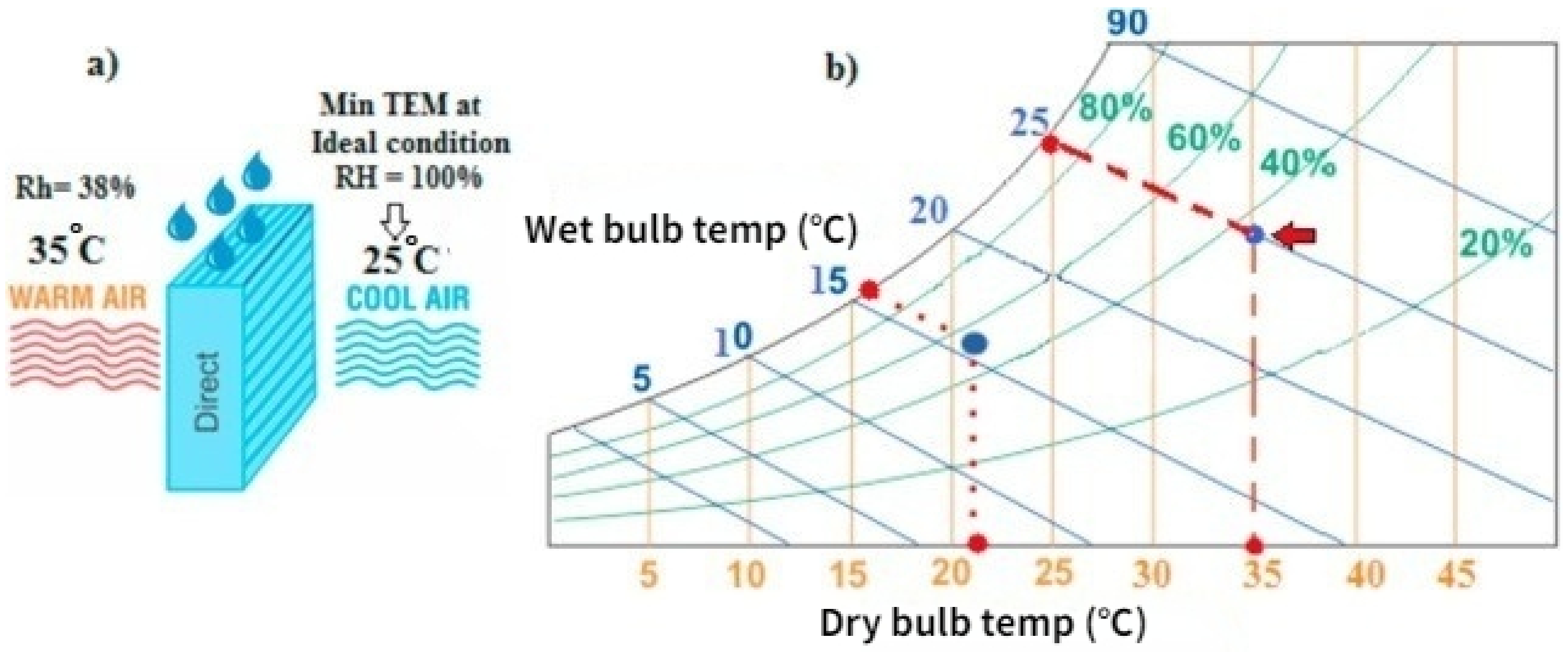
2.1. Direct Evaporative Cooling (DEC)

DEC allows the air to contact wet surfaces directly. Figure 1 shows a DEC system diagram and its cooling process in a psychometric chart [15]. From the figure, it can be found that the hot and dry outdoor air (35 °C and 38% relative humidity) flows over the cooling pad, which is fully wetted by water. After passing through the cooling pad, the air temperature decreases to 25 °C. This is because the heat and mass are exchanged between the air and water inside of the cooling pad during the cooling process. As the water evaporates, it absorbs the thermal energy from the water and air, which leads to a reduction of the dry-bulb temperature of the airstream and an increase in the humidity ratio [21]. The hot and dry inlet air turns into cool and humid conditions [22]. The thermal process could be regarded as an isenthalpic process; the temperature of supply air from the cooling pad could ideally approach the wet-bulb temperature of the inlet condition. Wet-bulb effectiveness is usually used to evaluate the DEC performance, which represents the ability of DEC to achieve the wet-bulb temperature of the supply air. It is defined by Equation (1) [23]:
ε w b = T d b , i n T d b , o u t T d b , i n T w b , i n
In a real situation, the DEC supply air temperature is always higher than the theoretical value. Many research studies indicate that DEC system effectiveness is significantly affected by the cooling pad material under the same inlet air conditions [24]. The material selection is crucial and widely studied. Abohorlu Doğramacı et al. [20] studied the potential of using eucalyptus fibers as evaporative cooling pad material. The study identified cheap, easy to access and sustainable materials to replace the currently used commercial products. According to their study, the maximum air temperature drop was 11.3 °C, the highest cooling efficiency was 71% and the highest coefficient of performance (COP) was 4.05. The research also presented a suggestion of an inlet air velocity of 0.6 m/s. Jain and Hindoliya [25] experimentally tested two cooling pad materials and compared them with conventional commercial products. Coconut fibers and Palash fibers were examined and the results revealed that these two materials could be alternatives of commercial fibers. It was shown that the temperature difference between the inlet and outlet air could reach 14.90 °C and 16.23 °C for coconut fibers and Palash fibers, respectively. In terms of wet-bulb efficiency, Palash fibers showed the highest effectiveness among all the tested materials, while for coconut fibers, the efficiency is slightly lower. Khosravi et al. [26] investigated five different evaporation materials through experiments with two operation modes. Wood chips were found as the best cooling pad material in direct evaporative cooling mode, which reduced the air temperature by 10.6 °C on average and has wet-bulb effectiveness of 81%. In another research work conducted by Laknizi et al. [27], pottery rods were selected as the cooling pad material. The temperature reduction, saturation efficiency, cooling capacity and COP are 7 °C, 65.87%, 539.7 W and 8.8, respectively. Al-Sulaiman [28] conducted experiments with three local fibers and one commercial product, which contain jute, palm, luffa, and aspen wood. Luffa was found to be the most promising material under the testing environment even compared with the commercial material. Velasco-Gómez et al. [29] explored a new evaporative cooling pad material made of cotton fabric. It was reported that the saturation efficiency could reach 100%, which means the outlet air temperature could be cooled to the wet-bulb temperature. The maximum temperature difference was obtained as 19.2 °C under a hot and dry inlet condition. Nada et al. [30] carried out experimental work using corrugated cellulose papers as evaporative cooling pad material. They reported that using a bee-hive structure of corrugated-cellulose papers could enhance heat and mass transfer compared to the conventional pad material. Information from the previous literature is summarized in Table 1.
In comparison to the vapor-compression air-conditioning system, DEC has a simple and compact structure, including a fan, cooling pad and water distribution system. The power consumption is mainly contributed by the fan and pump and are much lower than that consumed by the compressor. DEC uses an eco-friendly working fluid (water) instead of non-environmental refrigerants. Moreover, the efficiency of DEC is usually high due to the direct contact between supply air and water. However, there are also some drawbacks that restrict the DEC application. For example, the theoretical minimum supply air temperature cannot be below the wet-bulb temperature of the inlet air, which might not be able to meet the cooling requirement during humid weather conditions. Furthermore, direct contact between supply air and water could lead to an increment of air humidity ratio. For the buildings with occupants, there is a requirement for a humidity ratio range. If the air humidity ratio is too high, it would make humans feel uncomfortable and even cause health problems [31]. Consequently, DEC is more suitable for hot and arid locations where moisture control is not compulsory.

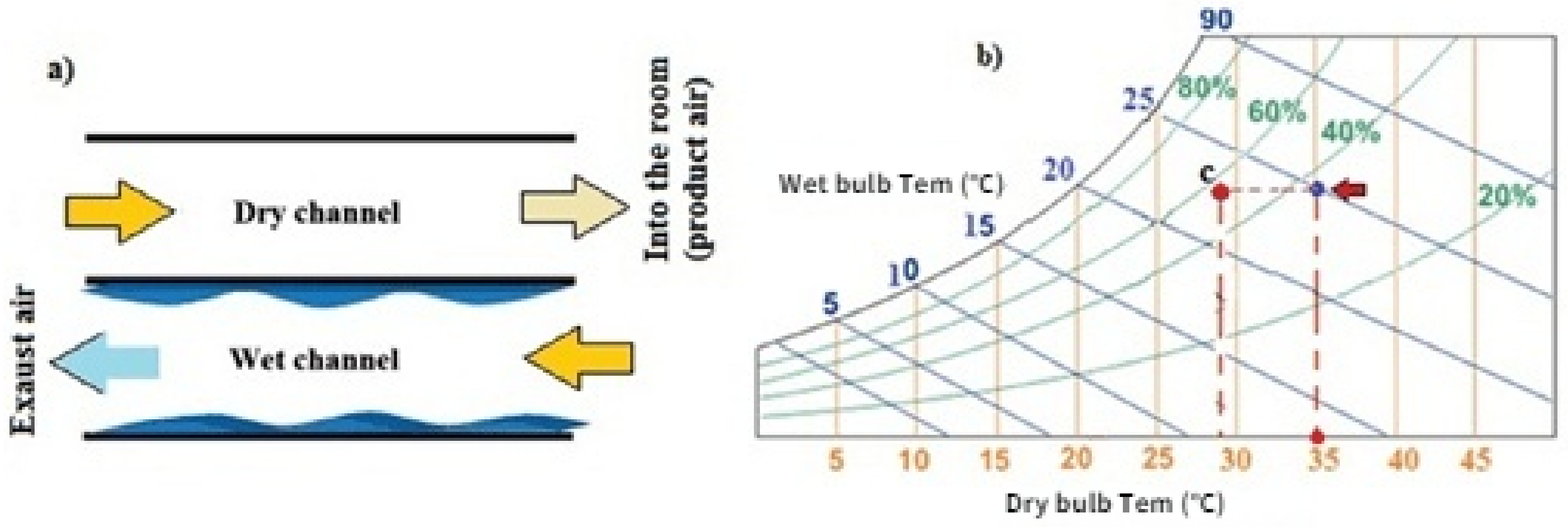
2.2. Indirect Evaporative Cooling (IEC)

A simple IEC is basically a DEC plus a heat exchanger, as shown in Figure 2, which can decrease the intake air temperature without adding extra moisture. It can be seen from Figure 2, in an IEC, there are two air channels for intake air and working air, and they are adjacent to each other. Inside the dry channel, the intake air is cooled by the wall between the two channels. The cooled product air is supplied to the conditioned space for the cooling purpose. On the other hand, the thin water film on the surface of the wet channel absorbs the heat from the dry channel via the wall and evaporates into water vapor, removing the heat. The working air flows through the wet channel, and the water vaporizes into the working air. The air vapor mixture is discharged into the environment after the wet channel. Although the conventional IEC solved the high humid ratio in the DEC, the IEC application is still limited due to the poor heat transfer rate and low wet-bulb effectiveness (<60%) [32]. It should be noted that the cooling temperature of IEC is also limited by the wet-bulb temperature of the inlet air. In this case, a stand-alone IEC is less desirable, so it is often integrated with a vapor-compressed chiller to further cool the supply air [1,7]. The simple IEC could eliminate the addition of moisture into supply air that is a disadvantage of DEC, but its minimum temperature would be higher than wet-bulb temperature as the heat transfer temperature has different requirements.
To improve the simple IEC, Maisotsenko proposed a new flow arrangement for IEC, termed as Maisotsenko-cycle (M-cycle) IEC. This concept made a great contribution to the IEC development [33,34,35]. M-cycle IEC theoretically could decrease the minimum temperature from DEC’s wet-bulb temperature down to the dew temperature of the intake air while avoiding the addition of moisture into the supply air [36,37,38]. Figure 3 shows the schematic of a single-stage M-cycle cooler and its cooling process in a psychrometric diagram. In an M-cycle IEC, the intake air flows into the dry channel in the same way as the conventional IEC. But at the end of the dry channel, partial air is extracted to enter the wet channel as the working air, and the remaining air is supplied to users. The ratio between the mass flow rate inside the dry and wet channels is called the working air ratio. Because of this flow arrangement, the working air is pre-cooled before entering the wet channel. Then the evaporation phenomenon takes place and makes the working air temperature approach a lower value, which also enhances the heat exchange rate between the dry and wet channels. Based on M-cycle, the product air is able to achieve a temperature below the ambient wet-bulb temperature, towards the dew point temperature of the inlet condition [39,40]. Except for the aforementioned wet-bulb effectiveness, another technical term called dew point effectiveness is often applied to access the IEC system performance as shown in Equation (2) [23]:
ε d p = T d b , i n T d b , o u t T d b , i n T d p , i n
In recent years, the system performance of M-cycle IEC has been widely studied through experimental, numerical and analytical methods. Improvements in flow arrangements, geometrical size, the water distribution system and adsorbent material are the major targets in these studies [13]. Cui et al. [42] introduced a configuration of M-cycle IEC simulated with CFD. In this configuration, the working air was totally separated from the product air while it was extracted from the product air at the end of the dry channel in previous studies. The model was validated with experiments. Some suggestions for device manufacturing and operation parameters were given based on the simulation results. The inlet air velocity should be below 1.5 m/s, ratios between channel length and height should be over 200, channel height should be smaller than 10 mm, channel height ratio between the dry channel and wet channel should be around 2 and the air ratio between product air and working air should be less than 1.5. Boukhanouf et al. [43] proposed a new structure of heat piped-porous ceramic tube integrated with regenerative IEC. A lab-scale prototype was built to test under various climate conditions. The experimental results showed that with this arrangement, the supply air temperature could be lower than 14 °C, and the overall COP reached up to 11.43. Xu et al. [44] conducted a numerical investigation on a guideless irregular heat and mass exchanger (HMX) with corrugated heat transfer surface using computational fluid dynamics (CFD) and engineering equation solver (EES). It was found that cooling capacity increased by 32.9–37%, COP increased by 29.7–33.3% and pressure drop reduced by 55.8–56.2%. Xu et al. [45] conducted an experimental investigation of the guideless irregular and corrugated surface structure HMX with Coolmax fabric. The experimental results revealed that with a working air ratio of 0.44, the cooling system had a better cooling performance compared to an existing commercial dew point cooler. The wet-bulb effectiveness and dew-point effectiveness reached 100–109.8% and 67–79.3%, respectively. At the optimum value of working air ratio of 0.364, the wet-bulb effectiveness and dew-point effectiveness reached 114% and 75% correspondingly, and COP significantly increased to 52.5. Arun and Mariappan [46] conducted an experimental test on a water distribution system. An ultrasonic transducer was used to produce water mist. The wick material inside the wet channel was not used because a thin water film could be formed by the new water distribution system. It was shown that the wet-bulb effectiveness reached 1.15, and the maximum temperature drop was 10 °C. Tariq et al. [47] developed an M-cycle by adding alumina nanoparticles into the water to improve the heat and mass transfer inside the wet channel. They demonstrated that when the ambient temperature is 45 °C, the cooling capacity and energy efficiency ratio (EER) increased by 18% and 19%, respectively. When the inlet air velocity increased to 1.6 m/s, the maximum increase of cooling capacity and EER could be as high as 54% and 22%. Nanoparticle volume fraction also showed a positive influence on system performance. However, a low concentration of nanofluid is recommended due to its feature of huge viscous loss at high concentrations. Tariq et al. [48] numerically tested the performance improvements of using aluminum-oxide, copper-oxide and titanium-oxide-based nanofluids inside of the M-cycle IEC. They found that with the assistance of aluminum nanofluid, enhancements could be observed in heat flux, wet-bulb effectiveness, dew point effectiveness, cooling capacity and EER. They also concluded that the optimum values for particle volume concentration and particle diameter are 1% and 20 nm. Kashyap et al. [49] studied four types of heat exchanger surfaces integrated with hybrid nanofluids. It reported that the plate surface modification had more obvious improvements than nanofluid types in all performance parameters. Among these four different surfaces, the capsule embossed surface was the best in terms of dew point effectiveness, COP and exergy efficiency.
From the above-mentioned studies, it can be concluded that M-cycle IEC could cool the supply air to a lower temperature than DEC. In addition, unlike DEC, no extra water vapor would be introduced into the supply air stream by using M-cycle IEC. M-cycle IEC also maintains the features of evaporative cooling in terms of power-saving, high-performance efficiency and being eco-friendly compared with conventional vapor-compressed cooling systems. However, the performance of M-cycle IEC is also influenced by the ambient conditions, which limits the application in humid regions. To overcome this major shortcoming, the hybrid evaporative cooling technology and other latent heat handling methods seem vital. A solid desiccant unit is one of the most promising approaches.

3. Overview of Solid Desiccant Dehumidification

Desiccant dehumidification has been widely studied and applied in air-conditioning systems to control the room humidity. The desiccant dryer could be classified into liquid desiccant and solid desiccant according to the desiccant material, and each has its own characteristics. The solid desiccant has a higher water adsorption rate, simpler structure and no carry-over risk compared to the liquid desiccant [50]. The dehumidification process is to remove the moisture of air through the strong water vapor attraction property of the desiccant material. The water vapor pressure difference between the desiccant surface and flowing air is the main driving force [51]. As the process air is continuously dehumidified, the desiccant materials become saturated, and sorption ability decreases, which requires a regeneration process [52]. Thermal energy is usually used to regenerate the desiccant unit, and this could be achieved using solar energy, electrical heater, electro-osmotic and waste heat [53,54,55]. To improve the desiccant system performance, many studies have been conducted from the aspects of improving water adsorption capacity and reducing regeneration temperature [56]. Zheng et al. [56] reviewed the recent developments of solid desiccant material by considering both adsorption isotherms and regeneration ability, which covered composite desiccants, nanoporous inorganic materials and polymetric desiccants. The results showed that the dehumidification and regeneration capacity of composite desiccant could be enhanced via host matrix and immersed salts selection. For nanoporous inorganic materials, a good balance between regeneration and adsorption could be identified by modifying the textural properties. However, further investigation into advanced materials is needed to fulfill all the demands of solid desiccant cooling systems.

4. Integrated Evaporative Cooling and Solid Desiccant System

4.1. Features of Solid Desiccant-Based Evaporative Cooling System

The temperature difference between the ambient dry-bulb temperature and dew-point temperature is an important indicator to determine the application eligibility of evaporative cooling technology. According to this criterion, evaporative cooling technology is not suggested in hot and humid areas [57]. In order to extend the application of evaporative cooling, integrated evaporative cooling with a solid desiccant unit gained lots of attention, and it is believed that the desiccant-based evaporative cooling system is one of the best alternatives to the vapor-compression system under wet and hot climates [58]. Compared with the traditional vapor-compression cooling system, the solid desiccant evaporative cooling system consumes less electricity, has no harmful refrigerant, controls air humidity effectively and maintains a high level of air quality [59]. The hybrid system usually includes two main processes: the dehumidification process and the evaporative cooling process. The function of the dehumidification process is to remove the moisture, and the evaporative cooling process is responsible for handling the sensible heat of the air. Some commonly used desiccant materials are silica gel, zeolites, alumina, hydratable salts and mixtures [12].
Figure 4 shows a typical solid desiccant-assisted evaporative cooling system configuration. From the configuration, the ambient air is dehumidified when flowing through the desiccant wheel. Then the dehumidified air flows through the sensible heat wheel, where it is cooled by the return air from the building zone. The cool, dry air then flows through the evaporative cooler and is further cooled and supplied to the building. The return air from the conditioned room flows through the evaporative cooler and is cooled. This cold air flows through the heat wheel, where it cools the supply air. Afterward, this return air is heated to the regenerative temperature in a heat exchanger by solar or electric energy. Then the high temperature returns airflow through the solid desiccant wheel, where the solid desiccant is regenerated. The exhaust air is discharged into the environment [60].

4.2. Development of the Integrated Cooling System

Solid desiccant-assisted evaporative cooling systems have been studied extensively from different aspects. Zadpoor and Golshan [61] investigated the performance enhancement of a gas turbine cycle with a desiccant-based evaporative cooling system; a comparative study was conducted between the proposed system and in combination with other types of evaporative cooling, such as direct evaporative and direct and indirect evaporative cooling. Numerical models were built based on the configuration and tested in three climatic conditions. The authors concluded that the performance enhancement obtained using this hybrid system was more obvious than the other evaporative cooling technologies for hot and humid climates. Khalid et al. [62] proposed four configurations of solar-assisted, pre-cooled hybrid desiccant cooling system and tested numerically and experimentally under Pakistan climates. The results showed that the fourth operation mode, which applied IEC for pre-cooling and DEC for post-cooling of the air, achieved the highest COP. However, none of these four operation modes could fully provide a cooling load without the assistance of the auxiliary cooling unit. For the city of Lahore’s climate, the hybrid system could only provide enough thermal comfort for three of the seven months of the cooling season. White et al. [63] used TRNSYS to study a solar-assisted desiccant two-stage evaporative cooling system without any backup heating equipment under Australian climates. The first stage of evaporative cooling was an IEC, and then the air passed into the second stage DEC for further cooling. The results revealed that the effectiveness of IEC, supply airflow rate and solar collector area were the main factors that would affect the thermal comfort of the building. The results also pointed out that the system was not suitable for tropical climates. Goldsworthy and White [64] numerically investigated the optimization of a desiccant cooling system design with IEC. The heat and mass transfer equations of the desiccant wheel and IEC were solved simultaneously. It was found that the hybrid system showed great potential to reduce energy consumption and greenhouse emission. The electrical COP could be greater than 20 when the regeneration temperature was 70 °C, supply and regeneration airflow ratio was 0.67 and the extraction air ratio of IEC was 0.3. Hatami et al. [65] conducted an optimization study of the solar collector surface requirement in a desiccant evaporative cooling cycle. They concluded that after considering the design parameters and operating conditions of the desiccant wheel, the compulsory solar collector areas could decrease by 45% compared to an empirical model. Parmar and Hindoliya [66] evaluated a desiccant cooling system performance under four types of climates in India (hot and dry, warm and humid, moderate and composite climates). From the research outcomes, the desiccant cooling system was suggested to use in warm and humid climates; the maximum system thermal COP achieved 4.98 when the flow rate ratio between the regeneration air and process air (R/P ratio) was 0.55. They also claimed that the increase of the R/P ratio led to an elevation of the regeneration heat load requirement and a reduction in system thermal COP. Angrisani et al. [67] compared three types of solar collectors applied in the solar desiccant cooling systems in terms of energy, environmental and economic performance with a reference system. A selection of 16 m 2 of the evacuated solar collectors was recommended to obtain a drop of 50.2% in energy consumption and 49.8% equivalent CO 2 emissions. But the economic payback period was over 20 years due to its high installation cost. Rafique et al. [59] developed a numerical model of desiccant evaporative cooling systems and conducted a feasibility analysis for a hot and humid city in Saudi Arabia. The results showed that this system was feasible to use in such weather conditions with optimum selection of the operating parameters. Ma and Guan [68] investigated the system performance of a solar desiccant evaporative cooling system for a commercial building under various climates in Australia. Performance parameters including thermal COP, annual primary energy consumption, annual energy saving and annual CO 2 emissions reduction were compared with a reference variable air volume system. The maximum energy saving and CO 2 emission reduction were obtained as 557 GJ and 121 tones per year, respectively, in Darwin. The highest values of 7 of thermal COP could be achieved during summertime in Darwin. They pointed out that the solar desiccant evaporative cooling technology was useful in Darwin, which has a tropical climate, while it was not a competitive approach for other climate regions. Ma et al. [69] evaluated several important performance parameters of a solar desiccant evaporative cooling system, which included solar fraction, electrical COP, electricity power consumption, CO 2 emissions reduction, payback period and net present value. A comparative study was also carried out between the proposed system and two other solar-assisted vapor-compression air cooling systems under Australian climates. The simulation results presented that the solar desiccant-evaporative cooling system is suitable for most Australian climates, especially for hot and humid places. A total of 82.1% of annual power saving, 178.45 tons of annual CO 2 emissions reduction, 3.9 years of payback period and AUD 466,199 net present value could be accomplished by applying this cooling system in Darwin. Ma et al. [70] conducted a parametric study on solar collector area, solar thermal storage tank volume and backup heater capacity for a cooling system under Australian climates. It was shown that both increasing solar collector areas or solar thermal storage tanks could lead to solar fraction and electrical COP increase, but the tank volume was more sensitive to affect the system. A humidity control set point was also given as 0.008 kg/kg by considering indoor design conditions and electricity usage of the backup heater. Narayanan et al. [71] evaluated a desiccant evaporative cooling system for a residential building in Brisbane by using TRNSYS software. They found that this type of system could provide thermal comfort for about 50% of the time required for cooling. They also concluded that the system performance was mainly affected by the evaporative cooling system, heat recovery system and desiccant regeneration process.

5. Recent Research and Development to Improve the Performance of a Solid Desiccant Evaporative Cooling System

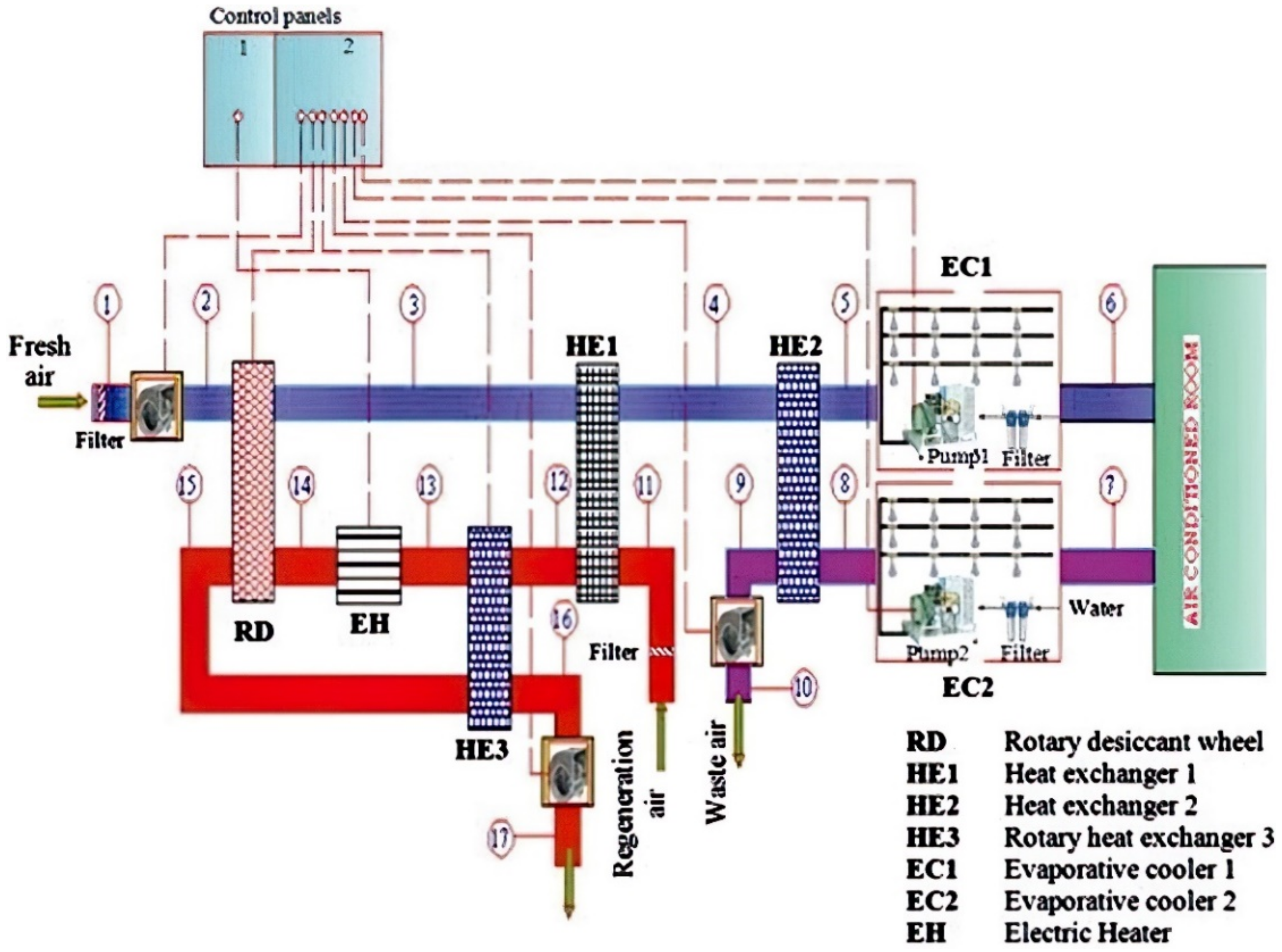
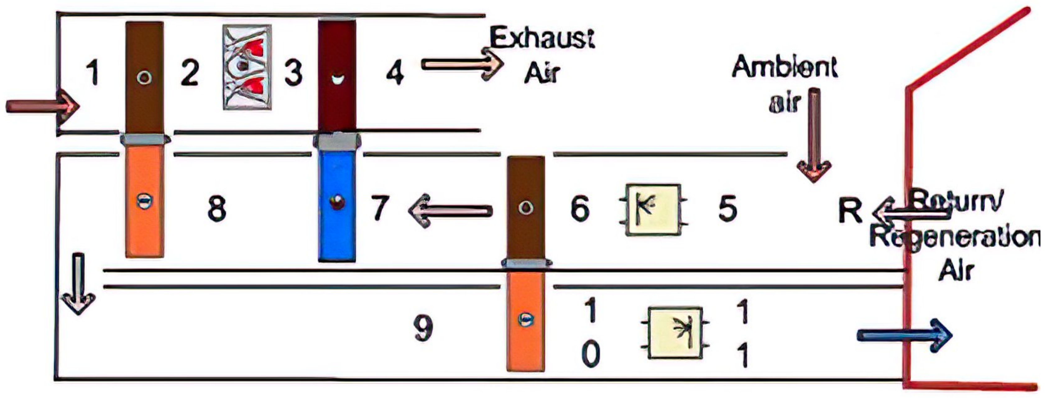
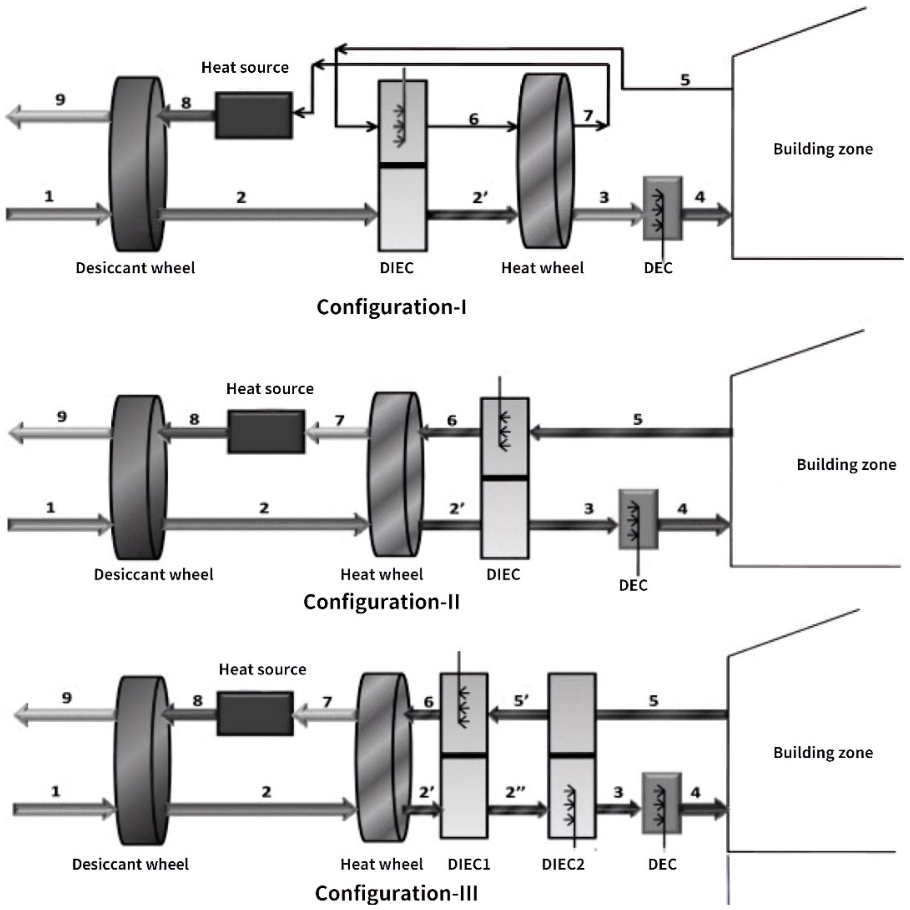
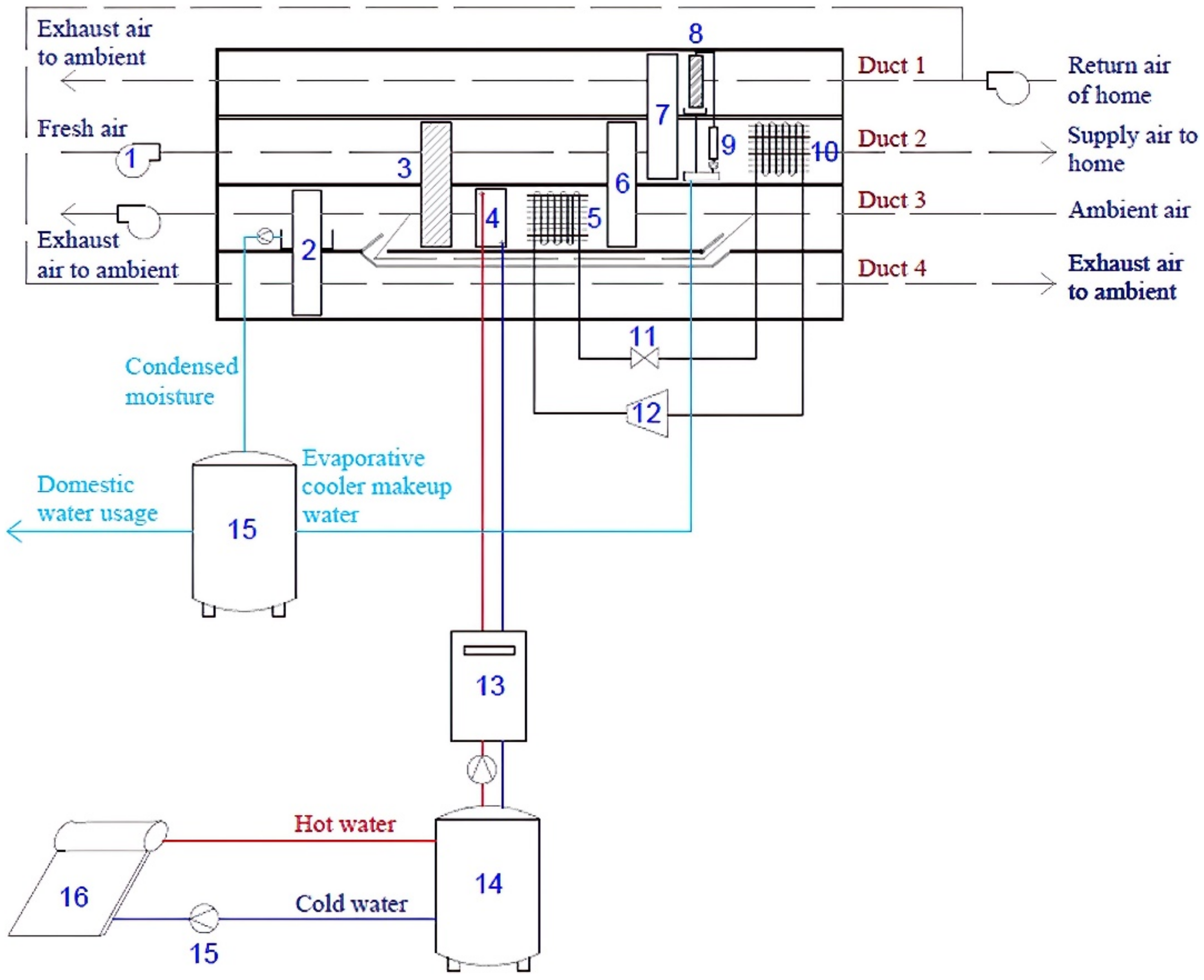
5.1. Improvement in System Configuration

Uçkan et al. [72] conducted an experimental study on a proposed configuration of desiccant-based ECT (see Figure 5). The novelty of the configuration was to employ the ambient air with high temperature and low absolute humidity as regeneration air. In this study, the supply air temperature could be cooled to around 14 °C when the initial temperature was 35 °C. According to the definition of thermal comfort zone for evaporative cooling applications by ASHRAE, this novel configuration could fully meet comfort conditions in hot and humid areas. Ali et al. [73] performed a comprehensive study on the performance evaluation of the desiccant evaporative cooling system with different weather conditions. In this research work, five system configurations, including three standard systems and two modified systems, were assessed under five different climate zones via an equation-based object-oriented modeling and simulation method. According to the simulation results, it was concluded that the ventilated-dunkle cycle configuration (refer to Figure 6) is more desirable for use in continental (Vienna), temperate (Sao Paulo) and dry-summer subtropical (Adelaide) climates with thermal COPs of 0.405, 0.89 and 1.01, respectively. While the ventilation cycle is better suited for arid (Karachi) and sem-arid (Shanghai) climates with average thermal COPs of 2.43 and 3.03, respectively. Three new configurations (see Figure 7) were proposed by Elgendy et al. [74] to improve the system performance of a desiccant evaporative cooling system. Compared with the conventional system, each novel system has its own features: in configuration-I, a direct/indirect evaporative cooler was placed before the heat wheel, in configuration-II, the evaporative cooling system was positioned after the heat wheel and in configuration-III, an additional direct/indirect evaporative cooler was installed in the opposite way. The numerical model was validated using experimental data, and only 2.23% and 3.87% average errors were obtained for the temperature and humidity ratio, respectively. The simulation results revealed that the highest cooling capacity was achieved by using configuration-I and configuration-III had the highest thermal COP and air handling COP. In addition, configuration-III also showed a 54% higher than the conventional configuration in terms of average exergetic efficiency. Heidari et al. [75] proposed a new desiccant evaporative cooling system (see Figure 8) that could produce cooling and water at the same time. This configuration was numerically tested and compared with conventional vapor-compression systems for a 60 m 2 residential building in a hot and humid city of Iran. It was reported that not only the comfort temperature and relative humidity were achieved, but also around 590 L of water was produced per week to fulfill the water consumption of the evaporative cooler and domestic water usage.

5.2. Improvement in Solid Desiccant Sub-System

It was reported that the regeneration process of the desiccant wheel contributes to more than 50% of the total energy consumption of a solid desiccant-based evaporative cooling system [76]. When the fuel price increases, the energy cost for the drying process has the same trend, which makes the dehumidification process less attractive [50]. If the air flows over an infinite number of desiccant wheels and heat wheels, the thermodynamic process could be regarded as isothermal [77]. In another word, using a multi-stage desiccant wheel could lead to a lower requirement of regeneration temperature and a higher coefficient of performance. In this case, some investigations were conducted to analyze the influence of multi-stage desiccant arrangement on the whole desiccant evaporative cooling system. Dezfouli et al. [78] performed an annual simulation of four configurations of solar desiccant cooling systems (one-stage ventilation, one-stage recirculation, two-stage ventilation and two-stage recirculation) under Malaysian weather conditions. After the comparative analysis, the two-stage ventilation system was more attractive to use in hot and humid conditions due to its higher efficiency compared to the others. Supply air at 17.6 °C and 0.0096 kg/kg could be provided for cooling purposes when the initial air condition is 30 °C, 0.0200 kg/kg. Hands et al. [79] organized a one-year performance test on a two-rotor desiccant evaporative cooling system with the ability to handle 12,000 m 3 / h of air. With the assistance of this dehumidifier arrangement, the dehumidification performance was maximized, and the regeneration temperature requirement decreased from around 80 to 60 °C, which could be easily achieved by using flat plate solar collectors. Gadalla and Saghafifar [80] conducted a numerical study on an air pre-cooling two-stage desiccant air conditioning system. With the air pre-cooling process, the performance of the desiccant wheel was further improved, and the average thermal COP during the five cooling months was 1.77.
Some researchers tried to improve the performance of the solid desiccant system from different aspects. Ren et al. [81] explored the feasibility of utilizing a photovoltaic thermal collector-solar air heater (PVT-SAH) and a phase change material (PCM)-based thermal energy storage unit to regenerate the desiccant wheel, which aimed to operate the system for a whole day and could provide certain heating load in winter. With proper design and control strategies, using this hybrid unit to drive the desiccant wheel showed great potential under Brisbane’s weather conditions. Similarly, a PVT-PCM-based solar-assisted desiccant evaporative cooling system combined with a desalination unit has been assessed by Wang et al. [82]. According to the study, the maximum COP of the cooling system and water production was 0.411 and 4.9 L/h at a mass flow rate of 0.78 kg/s. It was also noted that this system was more efficient in hot and humid areas. Aydin et al. [83] conducted related experiments on a novel solid desiccant material (vermiculite-calcium chloride ( V CaCl 2 )) for a desiccant evaporative cooling system. The experimental results revealed that this composite material had strong moisture sorption ability when the ambient relative humidity was over 40%, while it also showed benefits in response time and cost. Therefore, V CaCl 2 was suggested to apply in future application of desiccant evaporative cooling systems. Zhou [84] performed TRNSYS simulations of a solar-assisted internally cooled desiccant evaporative cooling system and conventional vapor-compression cooling system for three types of commercial buildings under three climates of tropical, subtropical and temperate. The internally cooled desiccant wheel applied in this study had a 45% higher dehumidification ability than the conventional desiccant wheel. A super-adsorbent polymer was selected as the desiccant material, which had a better dehumidification performance at a low level of regeneration temperature (50 °C) than traditional desiccant materials, such as silica gel and zeolite. The simulation results showed that the system could provide sufficient cooling and save 26% energy compared with a conventional vapor-compression system under subtropical and temperate climatic conditions most of the time. However, for more than 28.36% of the working time in tropical regions, this system failed to meet thermal comfort requirements due to the lack of dehumidification capacity at low regeneration temperatures.

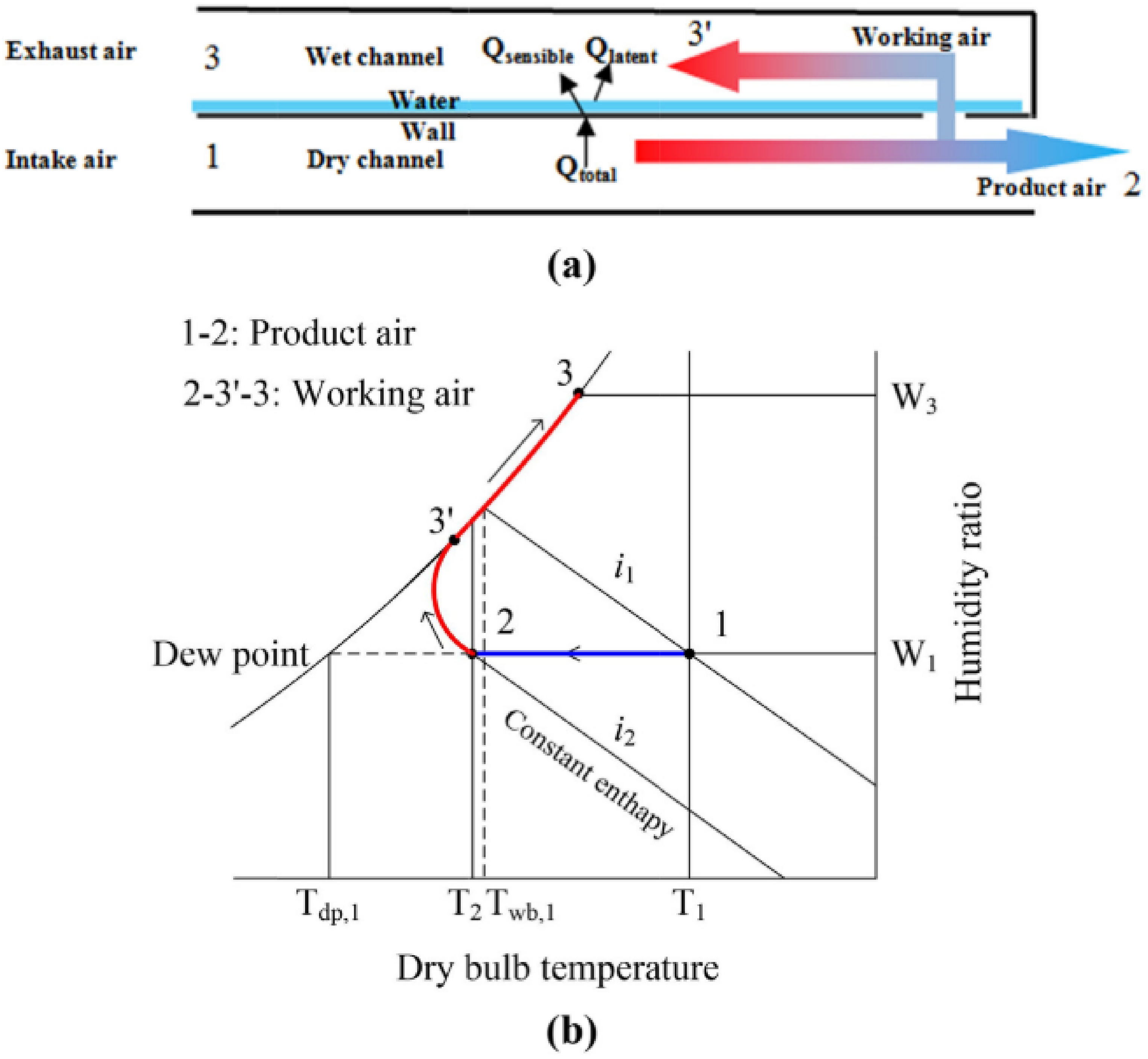
5.3. Integrated with M-Cycle IEC

Most desiccant-based evaporative cooling systems were coupled with DEC and conventional IEC. Although the evaporative cooling performance could be improved by the dehumidification process of the desiccant unit, the supply air still cannot meet the thermal comfort requirement for places with a high humidity ratio. With the development of evaporative cooling technology, research interests are attracted by coupling M-cycle IEC with the dehumidification approach. Saghafifar and Gadalla [85] presented a study on an inlet cooling system for a gas turbine power plant, integrating M-cycle IEC with the desiccant wheel, which is regenerated using the waste heat of the gas turbine. Three different inlet cooling systems combining M-cycle IEC were analyzed and compared with a conventional desiccant inlet cooling system. A total of USD 31.882 million savings was observed by applying an M-cycle IEC, and this hybrid system is the most economical technology for a 50 MWe gas turbine power plant in the UAE with a 25-year life cycle. Pandelidis et al. [86] used a modified ε -NTU method to simulate three types of desiccant-enhanced evaporative cooling systems, which included the cross-flow M-cycle IEC, count flow M-cycle IEC and the standard cross-flow evaporative cooler. The systems were compared with each other under various inlet air conditions and regeneration temperatures. The obtained simulation results showed that the system with the cross-flow M-cycle IEC was sensitive to the ambient humidity ratios, and it had the most complicated structure and could provide the lowest supply air temperature. The system with the regenerative M-cycle IEC was sensible on the air extraction ratio, and it was comparatively simpler and cheaper, which deemed it to be an alternative to the previous system. Gadalla and Saghafifar [80] investigated a two-stage desiccant evaporative cooling integrated with three M-cycle IECs installed at different locations for pre-cooling, intercooling or recovering purposes. The system that applied M-cycle IEC to pre-cool the inlet air was recommended compared with the other two systems, as this system increased the system thermal COP and reduced the regeneration temperature. Lin et al. [87] applied numerical and experimental methods to investigate the performance improvement of the dehumidification process on a cross-flow type M-cycle IEC. Their research work revealed that the wet-bulb effectiveness of the M-cycle IEC decreased from 1.25 to 0.86 when the ambient air humidity ratio changed from moderate to humid. A combination of dehumidification and evaporative cooling could greatly enhance the cooling capacity and energy efficiency by 70% to 135%, respectively, according to the moisture removal rate. Kashif Shahzad et al. [88] conducted an experimental evaluation of a solid desiccant M-cycle IEC cooling (MC-DAC) system. The system was compared with a typical conventional solid desiccant evaporative cooling (DAC) system. It was found that the MC-DAC system was 62.96% more efficient than the DAC in terms of thermal COP, but the cooling capacity of MC-DAC was 39.29% less due to the extraction air from the dry channel to the wet channel. In subtropical areas, the regeneration temperature of MC-DAC could be as low as 70 °C, and when the humidity ratio increased, the regeneration temperature requirement increment of the MC-DAC was less than that of DAC. Qadar Chaudhary et al. [89] conducted an experimental test on a solar-assisted cooling system, including a solid desiccant wheel and an M-cycle IEC. A 7.2   m 2 flat plate and 4.7   m 2 evacuated tube collectors were connected in a series by considering cost and thermal loss. The experiments were operated on selected days of three months of summertime in Taxila, Pakistan, from 10:00 a.m. to 4:00 p.m. The experimental results showed that this hybrid system could fully meet the cooling requirement in a hot and humid place with an average cooling capacity of 3.78 kW, a thermal COP of 0.91 and a solar fraction of 70%. Caliskan et al. [90] assessed a hybrid desiccant wheel and regenerative cooler system from the aspects of energy, exergy and sustainability. Analysis was performed under an ambient condition of 35 °C and 101.3 kPa. The researchers pointed out that even though the energy effectiveness of the system was high, the system could still be boosted based on exergy analysis. Because the largest exergy destruction ratio was 42.87% and the lowest sustainability was 1.62 of the desiccant wheel, the improvement of the desiccant wheel should be given priority. Caliskan et al. [91] analyzed the effect of unmodified ( ε dp = 0.67 ) and modified ( ε dp = 1 ) M-cycle IECs on the desiccant cooling system. With replacing with a higher effectiveness M-cycle IEC, the effectiveness of the whole system increased significantly in terms of wet-bulb effectiveness (from 0.95 to 2.16), dew point effectiveness (increasing from 0.63 to 1.43) and exergy efficiency (increasing from 18.40% to 41.93%). Pandelidis et al. [92] investigated four arrangements of desiccant evaporative cooling systems through numerical simulation and experiments. They found the configuration of the system B, which used cross-flow M-cycle for pre-cooling and counter-flow M-cycle for post-cooling, had the highest value of electrical EER (20.4), the second-highest thermal COP (1.7) and the minimum water consumption rate among the other arrangements. Due to these factors, system B was provided as an optimal solution to maintain thermal comfort under a temperate climate. Delfani and Karami [93] used TRNSYS to analyze three solid desiccant/M-cycle cooling systems under moderate and humid, hot and semi-humid and hot and humid climates. They concluded that the system with the M-cycle IEC in both supply air and return air streams could offer a supply air temperature below 16 °C, with the highest average thermal COP of 0.728 in moderate and humid climates and average regeneration temperature of 59.8 °C. The configuration utilizing the M-cycle IEC only in the supply air side had the highest solar fraction. Compared with conventional systems integrated with DEC, the configurations with M-cycle IEC showed a better cooling performance. A similar study was conducted by Ahmad et al. [94], studying two configurations with a combination of M-cycle IEC installed at the process air or regeneration air side. This numerical model was built by TRNSYS with the consideration of three different climates. The simulation results also proved that utilizing M-cycle IEC at both sides had the highest thermal COP and solar fraction in all three selected climates, 2.28 and 23.84% in hot desert conditions, 2.03 and 23.33% in subtropical and humid conditions and 2.12 and 46.86% in hot semi-arid conditions. Zhou [84] proposed a solid desiccant evaporative cooling system, which consists of an internally cooled desiccant wheel and M-cycle IEC. In this research work, the multiquadric-biharmonic method was used to build the simulation model of a commercialized M-cycle IEC. It was found that this hybrid system could save up to 50% electricity power in comparison to the conventional cooling system. Kashif et al. [95] studied a solid desiccant evaporative cooling system for livestock thermal comfort. Three types of the system were assessed: stand-alone M-cycle IEC (MEC), stand-alone desiccant air-conditioning and M-cycle-based desiccant air-conditioning. Stand-alone MEC was tested experimentally, and the wet-bulb effectiveness was from 46% to 78%. The investigation of M-cycle-based desiccant air-conditioning was conducted through theoretical methods, and a higher wet-bulb effectiveness was obtained from 70% to 86% with same the operating conditions. The findings indicated that the M-cycle-based desiccant air-conditioning system could maintain thermal comfort for livestock from March to September, while the stand-alone MEC could only provide sufficient cooling from March to June, and the stand-alone desiccant air-conditioning system failed to meet the cooling requirement in any month.
Replacing DEC/IEC with M-cycle IEC in solid desiccant evaporative cooling systems has been widely studied by many researchers. Table 2 presents a summary of selected publications. From Table 2, it can be found that different simulation methods have been used to build M-cycle IEC models. However, around 50% of studies simply assumed the wet-bulb effectiveness or dew point effectiveness is constant. Then the outlet temperature is calculated through Equation (1) or Equation (2). However, in a real situation, the effectiveness of M-cycle IEC is not consistent, as the ambient temperature and humidity ratio varies over time. This would lead to a remarkable error accumulation for a long-time analysis.

6. Evaluation Methods of the Solid Desiccant Evaporative Cooling System

6.1. Experimental Method

The main experimental investigations on solid desiccant-based evaporative cooling systems are illustrated in Table 3. It is noted that only a few experimental studies existed in the literature based on the literature survey. This is mainly caused by high initial construction cost and large geometric size. As it can be seen from Table 3, previous experimental studies mainly explore the following considerations.
  • Study of cooling performance of the hybrid system under hot and humid climates.
  • Evaluation of novel configuration on the thermal cooling performance.
  • Assessment of pre-cooling inlet air with an evaporative cooler.
  • Effect of multi-stage dehumidification on performance enhancement.
  • Analysis of combination of desiccant unit with M-cycle IEC.
  • Integration of solar thermal energy to reduce desiccant regeneration energy consumption.
Although each experiment has a different arrangement of configurations, evaporative cooler and desiccant unit, the experimental results are similar. It proves that the hybrid system can provide thermal cooling in hot and humid areas without the need for the backup cooling equipment. Most efforts have been made to improve dehumidification performance at low regeneration temperatures, to use solar energy to reduce regeneration energy usage and to use advanced evaporative cooling technology.

6.2. Numerical Method

In comparison with experimental approaches, numerical methods are more popular because they can provide accurate results within a short time and at a low cost. Among the numerical methods, the transient system simulation program (TRNSYS) was commonly adopted to simulate solid desiccant-based evaporative cooling systems [96]. TRNSYS is a flexible and component-based software package that mainly focuses on assessing the performance of thermal and electrical energy systems. Around 150 models are included in the TRNSYS library, which are written in Fortran, such as HVAC equipment, solar components and weather date processors. It is possible to easily connect and modify the existing components or even create your own models when necessary [97]. MATLAB, EnergyPlus and EES have also been used to simulate the hybrid system. ε -NTU and finite element/difference/volume methods are often applied to solve the heat and mass transfer equations of the system. For different numerical models, the major difference between each model is the assumptions adopted for building the models. The commonly used assumptions in the literature are listed below. In fact, most of the assumptions are made for simplification of the numerical model, which will result in sacrificing accuracy. When a system is working at a steady-state, most assumptions are suitable to use. However, when it comes to a dynamic situation, some assumptions are not appropriate anymore. For example, the cooling performance of the evaporative cooler relies on the inlet air condition heavily, if the cooling effectiveness of the evaporative cooler is still assumed as a constant when the inlet air condition varies, a huge error will be obtained in the result. Table 4 shows the assumptions that are commonly used in numerical simulations.
  • Adiabatic system with no heat loss to the environment.
  • The system is operating at a stable state.
  • Laminar flow inside of the air ducts.
  • No air leakage and pressure loss.
  • Thermodynamic properties of air are constant.
  • The desiccant wheel is assumed as an inertial system due to its low rotation speed.
  • Desiccant regeneration temperature is from 60 to 120 °C.
  • Same flow rate at both dehumidification and regeneration sides.
  • Effectiveness of the evaporative cooler is constant.
  • Effectiveness of the heat exchanger is constant.
  • No axial heat conduction or mass diffusion in the desiccant unit.

7. Challenges and Future Research Direction

According to the literature review, as discussed above, it was found that numerous investigations have been made of the development of highly efficient and effective integrated ECTs with a solid desiccant system. Improvements made by researchers have been reviewed from configuration optimization, desiccant unit enhancement and integration of M-cycle; and the evaluation methods are also discussed in this paper. Despite the substantial improvements that have been achieved in energy consumption, cooling performance and system efficiency, further research work is still necessary as follows:
  • Further improvements should be made on M-cycle IEC. Novel structure arrangements should be explored that could potentially increase the heat transfer areas and decrease the geometric size of the cooler for the same cooling capacity. New materials with large surface areas for water evaporating and correspondent water distribution strategies should be further investigated to enhance water evaporation. Utilizing nanofluids as the working fluid instead of water to improve heat transfer rate has been discussed numerically by some researchers; as this conception still lacks experimental validation, related experiments could be conducted to gain a better understanding of this idea in the future.
  • Developing new solid desiccant materials with high performance and lower generation temperature requirements would be recommended for future research. Based on the literature, silica gel was commonly selected as the adsorbent material of the desiccant unit for most studies. Few studies investigated the effects of different desiccant materials on system performance. If a single desiccant unit with a new desiccant material can achieve the same dehumidification performance as a multi-stage desiccant unit arrangement, equipment space occupation requirement and initial cost can be reduced greatly.
  • In general, the warm and humid outlet air of the regeneration process is discharged to the environment directly, which is a potential waste. Future work could focus on recycling the waste heat and moisture of exhaust air. The waste heat could be recycled to preheat the regeneration air through simple modification of the configuration, and liquid water could be recovered from water vapor to reduce the water consumption of the evaporative coolers.
  • Extra efforts could be made to optimize the system configuration by considering both system performance and economic performance. Additional heat recovery cycle, desiccant unit and evaporative coolers could enhance the system performance indeed, but these also lead to an increase in complexity, cost and construction size of the system, which make it less favorable than a mechanical vapor-compression cooling system. A trade-off between economics and efficiency should be considered.
  • A specific operation strategy should be proposed based on the ambient humidity ratio. Existing studies often assumed the desiccant unit is continuously operating during its working time no matter what the humidity level is. However, the humidity ratio changes over time and a huge difference could even be observed in the same day. When the ambient air is dry enough, the supply air can be sent to M-cycle IEC directly to provide cooling solely by bypassing the desiccant unit. The desiccant unit only needs to operate when the environment humidity exceeds a set value.

8. Conclusions

In this paper, the recent developments of the ECT, including IEC, the solid desiccant systems and the integration of both, have been reviewed. The performance enhancement strategies for these technologies were also discussed. From the review, the following conclusions can be drawn:
  • ECT has been proven to be an energy-efficient alternative for vapor-compression air-conditioning systems, especially in hot and dry climates.
  • ECT includes DEC technology and IEC, including M-cycle IEC technologies. For the DEC technology, the recent R&D focuses on the cooling pad material. M-cycle IEC technology has attracted more and more attention and has been used in wider areas recently because of its capacity to overcome two major drawbacks of the DEC technology while keeping its energy merits. However, it was found that the performance of an M-cycle IEC was not satisfactory when the ambient relative humidity (RH) was 70% or above.
  • The evaporative cooling technology integrated with the solid desiccant unit could extend the DEC application under different climate conditions. However, the conventional solid desiccant-based evaporative cooling system still cannot fulfill the cooling requirement when the humidity ratio is too high. Optimizing the system configuration, improving desiccant sub-system and integrating M-cycle are the three commonly used approaches. Among these methods, applying M-cycle IEC instead of conventional ECT is the most effective one because it reduces supply air temperature significantly and requires few additional modifications to the system. Improvements in configuration and desiccant sub-system also present some advantages in energy recovery and power saving. However, high construction cost and large system geometrical size are also present, which partially offset the benefits.
  • Most of the electricity of the integrated system is consumed by the regeneration process of the desiccant unit. Solar energy and industrial waste heat could be introduced to offset part of electricity usage via simple modifications to the system.
  • With novel system configuration and proper evaporative coolers arrangements, the COP of conventional solid desiccant evaporative cooling systems could be improved, and the system could meet cooling requirements in hot and semi-humid conditions. A few studies also concluded that their proposed configurations of solid desiccant evaporative cooling systems could maintain thermal comfort even in hot and humid areas.
  • A two-stage desiccant arrangement has been proven to be able to improve the dehumidification performance with a lower regeneration temperature, but its cost-effectiveness needs to be further studied. Other approaches, such as developing novel desiccant material with a high water adsorption rate and lower regeneration temperature requirement, adopting internally cooled desiccant wheel arrangement and using PVT and PCM to drive the desiccant wheel, are also effective for improving solid desiccant unit performance.
  • Replacing conventional DEC or IEC with M-cycle IEC in the solid desiccant evaporative cooling system is another attempt to improve the supply air temperature, system COP and humid climate adaptability, which was proven to work preliminarily. Further research is also required.

Author Contributions

Conceptualization, L.L. and X.W.; supervision, X.W., G.K. and E.H.; writing—L.L.; writing—review and editing, X.W., G.K. and E.H. All authors have read and agreed to the published version of the manuscript.

Funding

This research received no external funding. The APC is provided by Gholamreza Kefayati.

Conflicts of Interest

The authors declare no conflict of interest.

References

  1. Glanville, P.; Kozlov, A.; Maisotsenko, V. Dew point evaporative cooling: Technology review and fundamentals. ASHRAE Trans. 2011, 117, 111–118. [Google Scholar]
  2. Hasan, A. Going below the wet-bulb temperature by indirect evaporative cooling: Analysis using a modified ε-NTU method. Appl. Energy 2012, 89, 237–245. [Google Scholar] [CrossRef]
  3. Vitte, T.; Brau, J.; Chatagnon, N.; Woloszyn, M. Proposal for a new hybrid control strategy of a solar desiccant evaporative cooling air handling unit. Energy Build. 2008, 40, 896–905. [Google Scholar] [CrossRef]
  4. Chen, X.; Riffat, S.; Bai, H.; Zheng, X.; Reay, D. Recent progress in liquid desiccant dehumidification and air-conditioning: A review. Energy Built Environ. 2020, 1, 106–130. [Google Scholar] [CrossRef]
  5. Pérez-Lombard, L.; Ortiz, J.; Pout, C. A review on buildings energy consumption information. Energy Build. 2008, 40, 394–398. [Google Scholar] [CrossRef]
  6. Chan, H.-Y.; Riffat, S.B.; Zhu, J. Review of passive solar heating and cooling technologies. Renew. Sustain. Energy Rev. 2010, 14, 781–789. [Google Scholar] [CrossRef]
  7. Hasan, A. Indirect evaporative cooling of air to a sub-wet bulb temperature. Appl. Therm. Eng. 2010, 30, 2460–2468. [Google Scholar] [CrossRef]
  8. Duan, Z.; Zhan, C.; Zhang, X.; Mustafa, M.; Zhao, X.; Alimohammadisagvand, B.; Hasan, A. Indirect evaporative cooling: Past, present and future potentials. Renew. Sustain. Energy Rev. 2012, 16, 6823–6850. [Google Scholar] [CrossRef]
  9. Rafique, M.M.; Gandhidasan, P.; Rehman, S.; Al-Hadhrami, L.M. A review on desiccant based evaporative cooling systems. Renew. Sustain. Energy Rev. 2015, 45, 145–159. [Google Scholar] [CrossRef]
  10. Riangvilaikul, B.; Kumar, S. An experimental study of a novel dew point evaporative cooling system. Energy Build. 2010, 42, 637–644. [Google Scholar] [CrossRef]
  11. Jani, D.B.; Mishra, M.; Sahoo, P.K. Performance analysis of a solid desiccant assisted hybrid space cooling system using TRNSYS. J. Build. Eng. 2018, 19, 26–35. [Google Scholar] [CrossRef]
  12. Buker, M.S.; Riffat, S.B. Recent developments in solar assisted liquid desiccant evaporative cooling technology—A review. Energy Build. 2015, 96, 95–108. [Google Scholar] [CrossRef]
  13. Pacak, A.; Worek, W. Review of Dew Point Evaporative Cooling Technology for Air Conditioning Applications. Appl. Sci. 2021, 11, 934. [Google Scholar] [CrossRef]
  14. Porumb, B.; Ungureşan, P.; Tutunaru, L.F.; Şerban, A.; Bălan, M. A Review of Indirect Evaporative Cooling Operating Conditions and Performances. Energy Procedia 2016, 85, 452–460. [Google Scholar] [CrossRef] [Green Version]
  15. Dizaji, H.S.; Hu, E.J.; Chen, L. A comprehensive review of the Maisotsenko-cycle based air conditioning systems. Energy 2018, 156, 725–749. [Google Scholar] [CrossRef] [Green Version]
  16. Sajjad, U.; Abbas, N.; Hamid, K.; Abbas, S.; Hussain, I.; Ammar, S.M.; Sultan, M.; Ali, H.M.; Hussain, M.; Rehman, T.-U.; et al. A review of recent advances in indirect evaporative cooling technology. Int. Commun. Heat Mass Transf. 2021, 122, 105140. [Google Scholar] [CrossRef]
  17. Sofia, E.; Putra, N. Evaporative cooling innovations—A review. Presented at the International Conference on Trends in Material Science and Inventive Materials: ICTMIM 2020, Coimbatore, India, 9–10 April 2020. [Google Scholar]
  18. Yang, Y.; Cui, G.; Lan, C.Q. Developments in evaporative cooling and enhanced evaporative cooling—A review. Renew. Sustain. Energy Rev. 2019, 113, 109230. [Google Scholar] [CrossRef]
  19. Bruno, F. On-site experimental testing of a novel dew point evaporative cooler. Energy Build. 2011, 43, 3475–3483. [Google Scholar] [CrossRef]
  20. Doğramacı, P.A.; Riffat, S.; Gan, G.; Aydın, D. Experimental study of the potential of eucalyptus fibres for evaporative cooling. Renew. Energy 2019, 131, 250–260. [Google Scholar] [CrossRef]
  21. Martín, R.H. Numerical simulation of a semi-indirect evaporative cooler. Energy Build. 2009, 41, 1205–1214. [Google Scholar] [CrossRef]
  22. Anisimov, S.; Pandelidis, D.; Danielewicz, J. Numerical analysis of selected evaporative exchangers with the Maisotsenko cycle. Energy Convers. Manag. 2014, 88, 426–441. [Google Scholar] [CrossRef]
  23. Erens, P.J.; Dreyer, A.A. Modelling of indirect evaporative air coolers. Int. J. Heat Mass Transf. 1993, 36, 17–26. [Google Scholar] [CrossRef]
  24. Xu, P.; Ma, X.; Zhao, X.; Fancey, K.S. Experimental investigation on performance of fabrics for indirect evaporative cooling applications. Build. Environ. 2016, 110, 104–114. [Google Scholar] [CrossRef]
  25. Jain, J.K.; Hindoliya, D.A. Experimental performance of new evaporative cooling pad materials. Sustain. Cities Soc. 2011, 1, 252–256. [Google Scholar] [CrossRef]
  26. Khosravi, N.; Aydin, D.; Nejhad, M.K.; Dogramaci, P.A. Comparative performance analysis of direct and desiccant assisted evaporative cooling systems using novel candidate materials. Energy Convers. Manag. 2020, 221, 113167. [Google Scholar] [CrossRef]
  27. Laknizi, A.; Abdellah, A.B.; Faqir, M.; Essadiqi, E.; Dhimdi, S. Performance characterization of a direct evaporative cooling pad based on pottery material. Int. J. Sustain. Eng. 2019, 14, 46–56. [Google Scholar] [CrossRef]
  28. Al-Sulaiman, F. Evaluation of the performance of local fibers in evaporative cooling. Energy Convers. Manag. 2002, 43, 2267–2273. [Google Scholar] [CrossRef]
  29. Velasco-Gómez, E.; Tejero-González, A.; Jorge-Rico, J.; Rey-Martínez, F.J. Experimental Investigation of the Potential of a New Fabric-Based Evaporative Cooling Pad. Sustainability 2020, 12, 7070. [Google Scholar] [CrossRef]
  30. Nada, S.A.; Elattar, H.F.; Mahmoud, M.A.; Fouda, A. Performance enhancement and heat and mass transfer characteristics of direct evaporative building free cooling using corrugated cellulose papers. Energy 2020, 211, 118678. [Google Scholar] [CrossRef]
  31. Tariq, R.; Sheikh, N.A. Maisotsenko cycle based counter and cross flow heat and mass exchanger: A computational study. In Proceedings of the 2017 International Conference on Energy Conservation and Efficiency, Lahore, Pakistan, 22–23 November 2017; pp. 44–49. [Google Scholar] [CrossRef]
  32. Wang, Y.; Huang, X.; Li, L. Comparative Study of the Cross-Flow Heat and Mass Exchangers for Indirect Evaporative Cooling Using Numerical Methods. Energies 2018, 11, 3374. [Google Scholar] [CrossRef] [Green Version]
  33. Lv, J.; Yi, J.; Fu, Y.; Liu, H. Experimental and numerical study of a multi-unit evaporative cooling device in series. Case Stud. Therm. Eng. 2020, 21, 100727. [Google Scholar] [CrossRef]
  34. Cui, X.; Yang, X.; Kong, Q.; Meng, X.; Jin, L. Performance evaluation and comparison of multistage indirect evaporative cooling systems in two operation modes. Int. J. Energy Res. 2019, 44, 9298–9308. [Google Scholar] [CrossRef]
  35. Chen, Q.; Burhan, M.; Shahzad, M.W.; Ybyraiymkul, D.; Akhtar, F.H.; Ng, K.C. Simultaneous production of cooling and freshwater by an integrated indirect evaporative cooling and humidification-dehumidification desalination cycle. Energy Convers. Manag. 2020, 221, 113169. [Google Scholar] [CrossRef]
  36. Dizaji, H.S.; Hu, E.J.; Chen, L.; Pourhedayat, S. Development and validation of an analytical model for perforated (multi-stage) regenerative M-cycle air cooler. Appl. Energy 2018, 228, 2176–2194. [Google Scholar] [CrossRef]
  37. Dizaji, H.S.; Hu, E.J.; Chen, L.; Pourhedayat, S. Analytical/experimental sensitivity study of key design and operational parameters of perforated Maisotsenko cooler based on novel wet-surface theory. Appl. Energy 2020, 262, 114557. [Google Scholar] [CrossRef]
  38. Dizaji, H.S.; Hu, E.J.; Chen, L.; Pourhedayat, S. Comprehensive exergetic study of regenerative Maisotsenko air cooler; formulation and sensitivity analysis. Appl. Therm. Eng. 2019, 152, 455–467. [Google Scholar] [CrossRef]
  39. Zhan, C.; Duan, Z.; Zhao, X.; Smith, S.; Jin, H.; Riffat, S. Comparative study of the performance of the M-cycle counter-flow and cross-flow heat exchangers for indirect evaporative cooling—Paving the path toward sustainable cooling of buildings. Energy 2011, 36, 6790–6805. [Google Scholar] [CrossRef]
  40. Sohani, A.; Sayyaadi, H.; Mohammadhosseini, N. Comparative study of the conventional types of heat and mass exchangers to achieve the best design of dew point evaporative coolers at diverse climatic conditions. Energy Convers. Manag. 2018, 158, 327–345. [Google Scholar] [CrossRef]
  41. Duan, Z.; Zhan, C.; Zhao, X.; Dong, X. Experimental study of a counter-flow regenerative evaporative cooler. Build. Environ. 2016, 104, 47–58. [Google Scholar] [CrossRef]
  42. Cui, X.; Chua, K.J.; Islam, M.R.; Yang, W.M. Fundamental formulation of a modified LMTD method to study indirect evaporative heat exchangers. Energy Convers. Manag. 2014, 88, 372–381. [Google Scholar] [CrossRef]
  43. Boukhanouf, R.; Amer, O.; Ibrahim, H.; Calautit, J. Design and performance analysis of a regenerative evaporative cooler for cooling of buildings in arid climates. Build. Environ. 2018, 142, 1–10. [Google Scholar] [CrossRef]
  44. Xu, P.; Ma, X.; Diallo, T.M.O.; Zhao, X.; Fancey, K.; Li, D.; Chen, H. Numerical investigation of the energy performance of a guideless irregular heat and mass exchanger with corrugated heat transfer surface for dew point cooling. Energy 2016, 109, 803–817. [Google Scholar] [CrossRef] [Green Version]
  45. Xu, P.; Ma, X.; Zhao, X.; Fancey, K. Experimental investigation of a super performance dew point air cooler. Appl. Energy 2017, 203, 761–777. [Google Scholar] [CrossRef]
  46. Arun, B.S.; Mariappan, V. Experimental study of an ultrasonic regenerative evaporative cooler for a desiccant cooling system. Build. Serv. Eng. Res. Technol. 2018, 40, 151–175. [Google Scholar] [CrossRef]
  47. Tariq, R.; Zhan, C.; Zhao, X.; Sheikh, N.A. Numerical study of a regenerative counter flow evaporative cooler using alumina nanoparticles in wet channel. Energy Build. 2018, 169, 430–443. [Google Scholar] [CrossRef]
  48. Tariq, R.; Zhan, C.; Sheikh, N.A.; Zhao, X. Thermal Performance Enhancement of a Cross-Flow-Type Maisotsenko Heat and Mass Exchanger Using Various Nanofluids. Energies 2018, 11, 2656. [Google Scholar] [CrossRef] [Green Version]
  49. Kashyap, S.; Sarkar, J.; Kumar, A. Effect of surface modifications and using hybrid nanofluids on energy-exergy performance of regenerative evaporative cooler. Build. Environ. 2021, 189, 107507. [Google Scholar] [CrossRef]
  50. Misha, S.; Mat, S.; Ruslan, M.H.; Sopian, K. Review of solid/liquid desiccant in the drying applications and its regeneration methods. Renew. Sustain. Energy Rev. 2012, 16, 4686–4707. [Google Scholar] [CrossRef]
  51. Frein, A.; Muscherà, M.; Scoccia, R.; Aprile, M.; Motta, M. Field testing of a novel hybrid solar assisted desiccant evaporative cooling system coupled with a vapour compression heat pump. Appl. Therm. Eng. 2018, 130, 830–846. [Google Scholar] [CrossRef]
  52. Baniyounes, A.M.; Liu, G.; Rasul, M.G.; Khan, M.M.K. Analysis of solar desiccant cooling system for an institutional building in subtropical Queensland, Australia. Renew. Sustain. Energy Rev. 2012, 16, 6423–6431. [Google Scholar] [CrossRef]
  53. Manaf, I.A.; Durrani, F.; Eftekhari, M. A review of desiccant evaporative cooling systems in hot and humid climates. Adv. Build. Energy Res. 2018, 15, 1–42. [Google Scholar] [CrossRef]
  54. Abu-Hamdeh, N.H.; Almitani, K.H. Solar liquid desiccant regeneration and nanofluids in evaporative cooling for greenhouse food production in Saudi Arabia. Sol. Energy 2016, 134, 202–210. [Google Scholar] [CrossRef]
  55. Rambhad, K.S.; Walke, P.V.; Tidke, D.J. Solid desiccant dehumidification and regeneration methods—A review. Renew. Sustain. Energy Rev. 2016, 59, 73–83. [Google Scholar] [CrossRef]
  56. Zheng, X.; Ge, T.S.; Wang, R.Z. Recent progress on desiccant materials for solid desiccant cooling systems. Energy 2014, 74, 280–294. [Google Scholar] [CrossRef]
  57. Sohani, A.; Sayyaadi, H.; Hoseinpoori, S. Modeling and multi-objective optimization of an M-cycle cross-flow indirect evaporative cooler using the GMDH type neural network. Int. J. Refrig. 2016, 69, 186–204. [Google Scholar] [CrossRef]
  58. Balyani, H.H.; Sohani, A.; Sayyaadi, H.; Karami, R. Acquiring the best cooling strategy based on thermal comfort and 3E analyses for small scale residential buildings at diverse climatic conditions. Int. J. Refrig. 2015, 57, 112–137. [Google Scholar] [CrossRef]
  59. Rafique, M.M.; Gandhidasan, P.; Rehman, S.; Alhems, L.M. Performance analysis of a desiccant evaporative cooling system under hot and humid conditions. Environ. Prog. Sustain. Energy 2016, 35, 1476–1484. [Google Scholar] [CrossRef]
  60. Fong, K.F.; Lee, C.K. Solar desiccant cooling system for hot and humid region—A new perspective and investigation. Sol. Energy 2020, 195, 677–684. [Google Scholar] [CrossRef]
  61. Zadpoor, A.; Golshan, A. Performance improvement of a gas turbine cycle by using a desiccant-based evaporative cooling system. Energy 2006, 31, 2652–2664. [Google Scholar] [CrossRef]
  62. Khalid, A.; Mahmood, M.; Asif, M.; Muneer, T. Solar assisted, pre-cooled hybrid desiccant cooling system for Pakistan. Renew. Energy 2009, 34, 151–157. [Google Scholar] [CrossRef]
  63. White, S.D.; Kohlenbach, P.; Bongs, C. Indoor temperature variations resulting from solar desiccant cooling in a building without thermal backup. Int. J. Refrig. 2009, 32, 695–704. [Google Scholar] [CrossRef]
  64. Goldsworthy, M.; White, S. Optimisation of a desiccant cooling system design with indirect evaporative cooler. Int. J. Refrig. 2011, 34, 148–158. [Google Scholar] [CrossRef]
  65. Hatami, Z.; Saidi, M.H.; Mohammadian, M.; Aghanajafi, C. Optimization of solar collector surface in solar desiccant wheel cycle. Energy Build. 2012, 45, 197–201. [Google Scholar] [CrossRef]
  66. Parmar, H.; Hindoliya, D.A. Performance of solid desiccant-based evaporative cooling system under the climatic zones of India. Int. J. Low-Carbon Technol. 2012, 8, 52–57. [Google Scholar] [CrossRef]
  67. Angrisani, G.; Roselli, C.; Sasso, M.; Tariello, F. Assessment of Energy, Environmental and Economic Performance of a Solar Desiccant Cooling System with Different Collector Types. Energies 2014, 7, 6741–6764. [Google Scholar] [CrossRef] [Green Version]
  68. Ma, Y.; Guan, L. Performance Analysis of Solar Desiccant-Evaporative Cooling for a Commercial Building under Different Australian Climates. Procedia Eng. 2015, 121, 528–535. [Google Scholar] [CrossRef] [Green Version]
  69. Ma, Y.; Saha, S.; Miller, W.; Guan, L. Comparison of Different Solar-Assisted Air Conditioning Systems for Australian Office Buildings. Energies 2017, 10, 1463. [Google Scholar] [CrossRef] [Green Version]
  70. Ma, Y.; Saha, S.C.; Miller, W.; Guan, L. Parametric Analysis of Design Parameter Effects on the Performance of a Solar Desiccant Evaporative Cooling System in Brisbane, Australia. Energies 2017, 10, 849. [Google Scholar] [CrossRef] [Green Version]
  71. Narayanan, R.; Halawa, E.; Jain, S. Performance Characteristics of Solid-Desiccant Evaporative Cooling Systems. Energies 2018, 11, 2574. [Google Scholar] [CrossRef] [Green Version]
  72. Uçkan, İ.; Yılmaz, T.; Hürdoğan, E.; Büyükalaca, O. Experimental investigation of a novel configuration of desiccant based evaporative air conditioning system. Energy Convers. Manag. 2013, 65, 606–615. [Google Scholar] [CrossRef]
  73. Ali, M.; Vukovic, V.; Sheikh, N.A.; Ali, H.M. Performance investigation of solid desiccant evaporative cooling system configurations in different climatic zones. Energy Convers. Manag. 2015, 97, 323–339. [Google Scholar] [CrossRef]
  74. Elgendy, E.; Mostafa, A.; Fatouh, M. Performance enhancement of a desiccant evaporative cooling system using direct/indirect evaporative cooler. Int. J. Refrig. 2015, 51, 77–87. [Google Scholar] [CrossRef]
  75. Heidari, A.; Roshandel, R.; Vakiloroaya, V. An innovative solar assisted desiccant-based evaporative cooling system for co-production of water and cooling in hot and humid climates. Energy Convers. Manag. 2019, 185, 396–409. [Google Scholar] [CrossRef]
  76. Park, J.-Y.; Dong, H.-W.; Cho, H.-J.; Jeong, J.-W. Energy benefit of a cascade liquid desiccant dehumidification in a desiccant and evaporative cooling-assisted building air-conditioning system. Appl. Therm. Eng. 2019, 147, 291–301. [Google Scholar] [CrossRef]
  77. Zhang, H.; Niu, J. A two-stage desiccant cooling system using low-temperature heat. Build. Serv. Eng. Res. Technol. 1999, 20, 51–55. [Google Scholar]
  78. Dezfouli, M.M.S.; Mat, S.; Pirasteh, G.; Sahari, K.S.M.; Sopian, K.; Ruslan, M.H. Simulation Analysis of the Four Configurations of Solar Desiccant Cooling System Using Evaporative Cooling in Tropical Weather in Malaysia. Int. J. Photoenergy 2014, 2014, 1–14. [Google Scholar] [CrossRef] [Green Version]
  79. Hands, S.; Sethuvenkatraman, S.; Peristy, M.; Rowe, D.; White, S. Performance analysis & energy benefits of a desiccant based solar assisted trigeneration system in a building. Renew. Energy 2016, 85, 865–879. [Google Scholar] [CrossRef]
  80. Gadalla, M.; Saghafifar, M. Performance assessment and transient optimization of air precooling in multi-stage solid desiccant air conditioning systems. Energy Convers. Manag. 2016, 119, 187–202. [Google Scholar] [CrossRef]
  81. Ren, H.; Ma, Z.; Lin, W.; Fan, W.; Li, W. Integrating photovoltaic thermal collectors and thermal energy storage systems using phase change materials with rotary desiccant cooling systems. Sustain. Cities Soc. 2018, 36, 131–143. [Google Scholar] [CrossRef] [Green Version]
  82. Wang, N.; Wang, D.; Dong, J.; Wang, H.; Wang, R.; Shao, L.; Zhu, Y. Performance assessment of PCM-based solar energy assisted desiccant air conditioning system combined with a humidification-dehumidification desalination unit. Desalination 2020, 496, 114705. [Google Scholar] [CrossRef]
  83. Aydin, D.; Charidi, M.; Khosravi, N. Synthesis and experimental investigation of V-CaCl2 composite desiccant for performance enhancement in evaporative cooling applications. Proc. Inst. Mech. Eng. Part E J. Process Mech. Eng. 2019, 234, 70–82. [Google Scholar] [CrossRef]
  84. Zhou, X. Thermal and energy performance of a solar-driven desiccant cooling system using an internally cooled desiccant wheel in various climate conditions. Appl. Therm. Eng. 2021, 185, 116077. [Google Scholar] [CrossRef]
  85. Saghafifar, M.; Gadalla, M. Innovative inlet air cooling technology for gas turbine power plants using integrated solid desiccant and Maisotsenko cooler. Energy 2015, 87, 663–677. [Google Scholar] [CrossRef]
  86. Pandelidis, D.; Anisimov, S.; Worek, W.M.; Drąg, P. Comparison of desiccant air conditioning systems with different indirect evaporative air coolers. Energy Convers. Manag. 2016, 117, 375–392. [Google Scholar] [CrossRef]
  87. Lin, J.; Wang, R.Z.; Kumja, M.; Bui, T.D.; Chua, K.J. Modelling and experimental investigation of the cross-flow dew point evaporative cooler with and without dehumidification. Appl. Therm. Eng. 2017, 121, 1–13. [Google Scholar] [CrossRef]
  88. Shahzad, M.K.; Chaudhary, G.Q.; Ali, M.; Sheikh, N.A.; Khalil, M.S.; Rashid, T.U. Experimental evaluation of a solid desiccant system integrated with cross flow Maisotsenko cycle evaporative cooler. Appl. Therm. Eng. 2018, 128, 1476–1487. [Google Scholar] [CrossRef]
  89. Chaudhary, G.Q.; Ali, M.; Sheikh, N.A.; Gilani, S.I.U.H.; Khushnood, S. Integration of solar assisted solid desiccant cooling system with efficient evaporative cooling technique for separate load handling. Appl. Therm. Eng. 2018, 140, 696–706. [Google Scholar] [CrossRef]
  90. Caliskan, H.; Lee, D.-Y.; Hong, H. Enhanced thermodynamic assessments of the novel desiccant air cooling system for sustainable energy future. J. Clean. Prod. 2019, 211, 213–221. [Google Scholar] [CrossRef]
  91. Caliskan, H.; Lee, D.-Y.; Hong, H. Assessments of High-Efficient Regenerative Evaporative Cooler Effects on Desiccant Air Cooling Systems. J. Energy Resour. Technol. 2020, 142, 072101. [Google Scholar] [CrossRef]
  92. Pandelidis, D.; Pacak, A.; Cichoń, A.; Drąg, P.; Worek, W.; Cetin, S. Numerical and experimental analysis of precooled desiccant system. Appl. Therm. Eng. 2020, 181, 115929. [Google Scholar] [CrossRef]
  93. Delfani, S.; Karami, M. Transient simulation of solar desiccant/M-Cycle cooling systems in three different climatic conditions. J. Build. Eng. 2020, 29, 101152. [Google Scholar] [CrossRef]
  94. Ahmad, W.; Ali, M.; Sheikh, N.A.; Akhtar, J. Effect of efficient multi-stage indirect evaporative cooling on performance of solar assisted desiccant air conditioning in different climatic zones. Heat Mass Transf. 2020, 56, 2725–2741. [Google Scholar] [CrossRef]
  95. Usman, M.; Niaz, H.; Sultan, M.; Miyazaki, T.; Feng, Y.; Shahzad, M.W.; Niaz, Y.; Waqas, M.M.; Alic, I. Study on Desiccant and Evaporative Cooling Systems for Livestock Thermal Comfort: Theory and Experiments. Energies 2020, 13, 2675. [Google Scholar] [CrossRef]
  96. Jani, D.B.; Bhabhor, K.; Dadi, M.; Doshi, S.; Jotaniya, P.V.; Ravat, H.; Bhatt, K. A review on use of TRNSYS as simulation tool in performance prediction of desiccant cooling cycle. J. Therm. Anal. Calorim. 2019, 140, 2011–2031. [Google Scholar] [CrossRef]
  97. Klein, S.; Beckman, W.; Mitchell, J.; Duffie, J.; Duffie, N.; Freeman, T.; Mitchell, J.; Braun, J.; Evans, B. TRNSYS 18: A Transient System Simulation Program; Solar Energy Laboratory, University of Wisconsin: Madison, WI, USA, 2017; Available online: http://sel.me.wisc.edu/trnsys (accessed on 29 April 2021).
  98. Lee, Y.; Park, S.; Kang, S. Performance analysis of a solid desiccant cooling system for a residential air conditioning system. Appl. Therm. Eng. 2021, 182, 116091. [Google Scholar] [CrossRef]
Figure 1. (a) System diagram of direct evaporative cooling (DEC); (b) DEC cooling process in a psychrometric chart [15].
Energies 14 05982 g001
Figure 2. (a) Working diagram of indirect evaporative cooling (IEC); (b) Cooling process of IEC in psychrometric chart [15].
Energies 14 05982 g002
Figure 3. (a) Working diagram of M-cycle IEC; (b) Working process of M-cycle IEC in psychrometric diagram [41].
Energies 14 05982 g003
Figure 4. Schematic diagram of solid desiccant-based evaporative cooling system [60].
Energies 14 05982 g004
Figure 5. Configuration of desiccant-based ECT system [72].
Energies 14 05982 g005
Figure 6. Schematic of ventilated-dunkle cycle [73].
Energies 14 05982 g006
Figure 7. Three proposed desiccant evaporative cooling systems (modified from [74]).
Energies 14 05982 g007
Figure 8. Scheme of novel desiccant cooling system with water production function [72].
Energies 14 05982 g008
Table 1. Summary of some investigations on different cooling pad materials.
Author(s)Cooling Pad MaterialMaximum Temperature Drops (°C)Air Velocity (m/s)Highest Wet-Bulb Efficiency (%)Cooling Capacity (kW)Maximum COP
Abohorlu Doğramacı et al. [20]Eucalyptus fibers11.30.6710.5184.05
Jain and Hindoliya [25]Coconut fibers
Palash fibers
14.9
16.23
1.4
1.4
78.60
83.89
-
-
-
-
Khosravi et al. [26]Wood chips10.6-810.9-
Laknizi et al. [27]Pottery rods7-65.870.53978.8
Al-Sulaiman [28]Luffa-2.455.1--
Velasco-Gómez et al. [29]Cotton fabric19.2-100--
Nada et al. [30]Corrugated-cellulose papers162.2856.1170
Table 2. Studies of solid desiccant evaporative cooling system using M-cycle IEC.
StudiesYearMethodDynamic Operation (Y/N)M-Cycle IEC TypeM-Cycle IEC Model
Saghafifar and Gadalla [85]2015NumericalY- ε d e w   p o i n t = 0.8
Pandelidis et al. [86]2016NumericalNRegenerative
Cross flow
ɛ-NTU-models
Gadalla and Saghafifar [80]2016NumericalY- ε d e w   p o i n t   = 0.8
Lin et al. [87]2017Numerical
Experimental
NCross flowBased on energy and mass balance equations
Kashif Shahzad et al. [88]2018ExperimentalNCross flow
Qadar Chaudhary et al. [89]2018ExperimentalY-
Caliskan et al. [90]2019NumericalNRegenerative
Caliskan et al. [91]2020NumericalNRegenerative
Perforated regenerative
ε r e g e n e r a t i v e   = 0.67
ε P e r f o r a t e d   = 1
Wang et al. [82]2020NumericalY- ε d e w   p o i n t   = 0.8
Pandelidis et al. [92]2020Numerical
Experimental
YRegenerative
Cross flow
Based on energy and mass balance equations
Delfani and Karami [93]2020NumericalYPerforated counter flowBased on energy and mass balance equations
Ahmad et al. [94]2020NumericalY-Regression model
Zhou [84]2021NumericalN-Multiquadric-biharmonic method
Kashif et al. [95]2021NumericalY-Regression model
Table 3. Experimental studies of solid desiccant evaporative cooling system.
Experimental StudiesYearDescription
Uçkan et al. [72]2013Analysis of novel configuration of solid desiccant-based evaporative cooling system.
Hands et al. [79]2016Performance analysis of a solar-assisted two-stage desiccant evaporative cooling system in a building, which can produce heating, cooling and hot water simultaneously.
Lin et al. [87]2017Comparative study of a cross flow M-cycle IEC with and without dehumidification.
Qadar Chaudhary et al. [89]2018Combination of solar desiccant-assisted cooler and M-cycle IEC.
Pandelidis et al. [92]2020Comparative study of pre-cooled desiccant system with different dew point coolers.
Kashif et al. [95]2020Assessment of desiccant-based evaporative cooling system for animals.
Table 4. Main assumptions used in numerical modeling.
Assumptions1234567891011
White et al. [63]
Parmar and Hindoliya [66]
Rafique et al. [59]
Elgendy et al. [74]
Heidari et al. [75]
Arun and Mariappan [46]
Lee et al. [98]
Publisher’s Note: MDPI stays neutral with regard to jurisdictional claims in published maps and institutional affiliations.

