1. Introduction
The multilevel inverter (MLI) structure is implemented as an alternative power range. MLI’s basic principle is that it uses multiple DC inputs with several low-rated semiconductor switches to synthesize stepped waveform stress to higher power rates. Different sources of power, such as batteries, capacitors, fuel cells and PV solar panels can be used with multiple sources of DC inputs in some topology of MLI. Power switches are controlled using appropriate algorithms to add all these different DC input voltages [
1].
During the last three decades, MLI research has gained a lot of attention as it has many advantages compared to the traditional two levels inverter using pulse width modulation (PWM). Firstly, it produces an output waveform with high quality. Secondly, it reduces voltage derivative (
) at the semiconductor switches that is because of the division of the total voltage stress on switches. Also, it has fewer power losses in switches as there are only conduction losses while the switching losses are minimal such as to be neglected, which leads to improving overall converter power efficiency. Moreover, the use of MLI improves the total harmonic distortion (THD) of output voltage and current with an increase in the number of levels and decreases the electromagnetic interference as well. Furthermore, it uses low-voltage semiconductor devices. Finally, because of the modularity in MLI, it can handle higher voltage and current [
2,
3,
4].
The main drawbacks of MLIs are the use of higher numbers of switching devices and independent DC sources, in addition to the complex methods of control of the switching intervals strategy [
5].
The high features and capabilities of the MLIs have caused its dependence in many industries and applications as electric vehicle drives, active filters, ship propulsion drives, rolling mills, induction motor controls, variable-speed motor drives, grid integration energy conversion systems like photovoltaic conversion systems, electrical transmission systems like high-voltage direct current (HVDC) and extra HVAC systems, etc. [
6,
7,
8].
The MLI has three major configurations that are used in industrial applications. The first configuration is the diode clamped MLI (DC-MLI), a single source of DC, where diodes are required to clamp the voltage on each DC bus to achieve output voltage levels. The main downside of this topology is a large number of clamping diodes when the level is high, and the DC capacitor balance is difficult [
9,
10].
The second configuration is the flying capacitor MLI (FC-MLI), where the voltages are clamped using capacitors. It needs large numbers of bulk capacitors; the capacitor voltage balance is more complicated, the switching control is complex, and the efficiency of actual power transmission is low [
11].
The third configuration is the CHB-MLI, where the connection of cascaded S numbers of single-bridge makes a (2
S + 1) level of the inverter. It is modular in circuit structure and all semiconductor devices are of the same power rating. This configuration is considered the perfect solution for the high-level inverter. But its main drawbacks are the increasing of switching numbers and separate DC sources [
12].
From the point of view of the switching frequency, the modulation switching, or control techniques are classified into high frequency switching techniques and fundamental switching techniques. The high switching technique involves sinusoidal pulse width modulation (SPWM), where the (n-1) triangular waves are applied as a carrier in n-levels inverter compared with a sinewave with the fundamental frequency. To enhance the harmonic distortion of output, phase-shifting or level-shifting techniques are applied. The advantages of high switching techniques are that the harmonics are far from the fundamental frequency which makes the filter small in size and low cost, but they have poor performance in total harmonic distortion as well as being complex in three-phase converters and high-level order [
13,
14].
The second method of switching technique is the fundamental switching techniques such as selective harmonic elimination (SHE) and space vector method (SVM). The main advantages of the fundamental switching techniques are low implementation complexity and low power loss. Among the different fundamental switching techniques, SHE is extensively used in medium and high-power applications so the basic idea for it is to eliminate certain low order harmonics with the desired value of fundamental component [
15]. However, the problem with the SHE technique is how to solve the set of trigonometric equations with the multiplicity of angles obtained after applying the analysis of the Fourier series on the output waveform [
16].
These sets of equations are by nature highly nonlinear and transcendental and may display multiple solutions, a single solution, or no solution in a different modulation index Mi. Three methods to solve these equations are the numerical solution, algebraic method, and evolutionary algorithms.
The Newton-Raphson method is an example of a numerical solution method that is deeply dependent on an initial guess that needs to be narrow for the exact solution. However, for a greater number of switching angles, the use of numerical techniques is not practical [
17]. The recently developed algebraic approaches include the resultant elimination theory and the Groebner bases of symmetrical polynomials [
18]. These approaches are difficult and time-consuming.
The methods of evolutionary algorithms include randomization searching methods optimizing an objective function. These methods can achieve SHE targets for all values of modulation indices (
Mi) for which a solution is available; they can also find an optimal solution for
Mi which has no solution. Many optimization algorithms are present in the literature, such as genetic algorithm (GA) [
19], particle swarm optimization (PSO) [
20], bee algorithm [
21], whale optimization algorithm [
22], teaching-learning-based Optimization (TLBO), and flower pollination algorithm (FPA) [
23].
In this paper, to solve the SHE problem, MPA is introduced as a newly emerging nature-inspired algorithm to have a better optimization solution applied on a three-phase 11-level CHB. This algorithm is selected based on its performance, efficiency, and ability to achieve global minima compared to the recent algorithms used to solve this problem such as TLBO, FPA, and hybrid PSO.
A three-phase balanced system was considered in this work, which is often used in applications in low-voltage, high-power industries.
Figure 1 shows a three-phase inverter with five different DC sources connected in cascade in each phase. The number of output voltage levels is given by 2
S + 1, Where
S is the number of separate DC sources and it is even describable as the number of switching angles. The inverter will be 11-level and
Van = (
V1 +
V2 +
V3 +
V4 +
V5) will give its phase voltage.
In this paper, two case studies are introduced and analyzed. They are the seven- and 11-level inverters for the evaluation of the MPA algorithm performance. For a seven-level cascaded H-bridge inverter, the experimental setup is carried out.
The losses equations derivations of power switches and reverse body-diode used in the three-phase seven-level MLI inverter are presented in detail. The power calculations are carried out on the real dynamic versions of the power switches obtained from the datasheet and experimental data. The simulation tool Piecewise Linear Electrical Circuit Simulation (PLECS) is used to measure losses using thermal model parameters.
2. Selective Harmonic Elimination (SHE) Modulation Technique
The SHE control method is a commonly accepted fundamental switching strategy for MLIs to obtain a better harmonic profile given the reduced switching loss and the retained fundamental level. By assessing a particular fitness function (FF), one may exclude the intended lower-order harmonics. In this respect, the generalized waveform of the staircase output voltage consideration of one switch per cycle as shown in
Figure 2 of (2
S + 1) levels inverter, can be given in terms of the Fourier series in Equation (1) [
24].
where
n = 1, 2, 3, …
The DC component
, the cosine component
and the even sine coefficient
are equal to zero due to the quarter-wave symmetry [
25,
26].
The term
for odd
is given as:
is the DC voltage of the source, and the phase output voltage can be expressed as Equation (3)
The SHE technique is used to control the fundamental component and eliminate certain lower order harmonics by determining the switching angles
αs. The aim is to solve the following set of equations:
Subject to: .
is defined as the modulation index and is the amplitude of fundamental component. In the three-phase inverter the triple harmonic components will be eliminated in the line voltage automatically.
This research presents MPA-based control scheme that is verified for the MLIs to get the best performance. The transcendental nonlinear equations are solved, and the solutions are preserved in the form of a lookup table. The angles then are decoded according to the controller used.
3. Marine Predators Algorithm (MPA)
MPA is a nature-inspired algorithm that simulates predator and prey movement according to what occurs in nature. Depending on different studies, there are two types of movement [
27,
28]. These are the Lévy technique for the area of low prey concentration and the Brownian movement technique for areas with an abundance of prey. As a result of environmental changes that may be natural or caused by humans, predators change their behavior in the hope of finding different distributions of prey. The choice between Lévy and Brownian is determined by the value of velocity ratio (
) of prey to predator.
If this velocity ratio is less than one () when the predator moves faster than the prey. The predator moves with a Lévy movement regardless of the movement of the prey, whether it is Lévy or Brownian movement.
For unit velocity ratio (), both the predator and the prey move at the same speed. If the prey moves in a Lévy form, the best way for the predator is Brownian movement.
In the case of high-velocity ratio () when the prey moves faster than the predator. Whether the prey is moving in any of the two strategies the best way is not to use Lévy and the optimum is not to move because the prey will come by itself.
The Mathematical Model of Lévy and Brownian Movements
The Brownian movement is a stochastic process, its steps are defined by a normal distribution with zero mean (
) and unit variance (
) the probability density function of this motion of random variable
is as follows [
29]:
The Lévy motion is a random process. The step sizes can be determined from a probability function known as the distribution of Lévy as follows in Equation (6):
where
is the power law exponent in the range
choosing
.
The normal distribution functions
x and
y with variance
And
is calculated as follows in Equation (8):
where
is a symbol of gamma function, and
.
MPA algorithm formulation is defined in the following terms:
In the first stage, a group of prey will be created as an initial population within the search space using the Equation (9):
where
,
are bounds of upper and lower vector in the search space, rand (0, 1) to generate a random number between [0,1].
The fitness of each predator is obtained after the prey matrix is initialized. The most suitable solution is filtered as a top predator to build an elite matrix (Equation (10)).
Arrays of this matrix are responsible for scanning and locating prey based on prey information. Where is the top predator vector which is multiplied n times to create the elite matrix , is the number of the search agent while d represents the number of the variables. The elite will be changed at the end of each iteration because the best predator replaces the top predator.
The prey matrix is one of the same dimensions as elite, in which the predators update their position. The prey matrix is built up as in Equation (11):
The whole process of MPA optimization is pertaining to these two matrices. The optimization formulation is divided into three phases depending on speed ratio ().
This phase is enforced at a high ratio of velocity (
). The best solution for a predator is not to move at all. This case happens in low iteration numbers (the first third of iterations); the mathematical model of this phase is as follows:
for
i = 1, 2, 3, …,
n.
In this phase, assuming that prey is in Brownian motion around the predator calculating its step size vector.
is a vector containing random numbers drawn from the standard normal distribution constituting the distribution. The notation
is an operation on two matrices of arbitrary size resulting in a block matrix. The product of
by prey expresses the Brownian motion of prey. Constant
P = 0.5, its value is recommended in [
30], and
R is a uniform random numbers vector in the range of [0,1].
This phase is corresponding to the unit velocity ratio (
). It occurs in the intermediate values of iterations (from the third of a maximum number of iterations to two-thirds of the maximum of iterations). The population is divided into two parts; consider the first half of the prey which moves in a Lévy manner with short steps according to the following mathematical model:
for
i = 1, …,
n/2.
The Lévy distribution vector is represented by vector based on Equation (6). The multiplication of , and Prey vector expresses the prey movement in Lévy manner.
The second half of the population is concerned with the predator, which moves in the Brownian movement as in the following mathematical model:
For i = n/2, …, n
So is the multiplication of
, and elite vector imitates the movement of a predator in Brownian motion, Equation (17) describes the manner of prey to move depending on the movement of predator in Brownian motion. The step size is controlled by the adaptive variable called CF, which is expressed by Equation (18):
This phase is corresponding to the low velocity ratio. It simulates in the remaining values of iterations, where that is the best strategy of predator is Lévy motion. The mathematical model of this phase is:
For i = 1, …, n
The movement of predator in Lévy motion update the new position of the prey.
Among the reasons that influence predator’s behavior are the eddy formation or fish aggregating devices (
FADs). Based on the study in [
31], if we take a shark as an example, it spends 80% of its life near
FADs, the remaining 20% take a longer journey in different areas to find an environment of other prey distribution, and it is the period that is considered while looking at the searching region of optimization. So, a constant
FAD is imposed (
FAD = 0.2) which expresses the possibility of an effect of
FADs on the optimization process. The mathematical model that expresses this phenomenon is described below:
where
is the binary matrix,
r is a random variable between [0,1]. For each array in
, if
r is greater than 0.2, then all values in this array are set to 1 and otherwise they are set to 0.
Subscripts denote random indices of array matrix.
The MPA pseudo-code illustrated below in Algorithm 1 describes the description of the algorithm proposed.
| Algorithm 1. MPA algorithm pseudo code |
| Set the population number of preys =n |
| dim=number of variables |
| Top_predator_fit==inf |
| Top_predator_pos=zeros (1, dim) |
| Top_predator_fit=inf. |
| FAD=0.2 |
| P=0.5 |
| Initialize of prey and top predator matrix (Preyi, Elittei) Equation (10,11) |
| While (Iter≤Max_Iter) |
| if (Iter≤Max_Iter/3) |
| Update prey matrix Equation (12,13) |
| else |
| if (Max_Iter/3<Iter<2*Max_Iter/3) |
| for population=1: n/2 |
| Update prey matrix Equation (14,15) |
| end for. |
| for population=n/2: n |
| Update prey matrix Equation (16,17) |
| end for. |
| else |
| if (Iter≥2*Max_Iter/3) |
| Update prey matrix Equation (19,20) |
| end if |
| Iter++ |
| end while |
| get the top predator position and its fitness value. |
| memory saving |
4. Performance Evaluation of MPA in SHE-MLI
In this section, the proposed MPA algorithm is applied on SHE equations and its performance is compared concerning the precision, and convergence probability with TLBO, hybrid PSOGWO, and FPA.
Proper fitness function, defined in Equation (22), considers targeted harmonics and fundamental component subject to constrain of SHE.
desired output fundamental voltage, V1 output fundamental voltage. λf is the fundamental peak voltage constraint to and λh is the limit for each harmonic peak voltage to V1. The upper bound of λf is reduced to as low as 2% to ensure the fundamental desired value is investigated. On the other hand, the upper limit of λh is also constrained to ensure that the eliminated harmonics does not exceed V1 by 3%, as recommended in the IEEE-519 standard.
For better THD, the values of
λf are chosen to be 0.01 and 0.02. To differentiate further between the first and the second term in FF, any value exceeding the fundamental term would be a strong penalty by the power of 4 and the term corresponding to harmonic by the power of 2 [
32,
33].
5. Comparison of Algorithms in 11-Level Inverter
Five H-bridges are connected in series to form an 11-level inverter. MPA is designed to resolve FF for estimating the optimum switching angles () to eliminate the fifth, seventh, eleventh, and thirteenth harmonics and provide the desired voltage of the fundamental component.
The proposed MPA algorithm is successfully implemented In MATLAB R2017a platform in a PC with Intel (R) Core™, i7, 2.7 GHz CPU (Intel, Santa Clara, CA, USA), and RAM built with 8.00 GB. Ten trails have to be checked before choosing the best solutions corresponding to minimum FF.
Figure 3 shows the fitness value MPA compared to FPA, TLBO and PSOGWO versus modulation index. With a step change of 0.01 and a variation of
Mi in a range 0.1 ≤
Mi ≤ 1, the number of iterations is 2000 for all algorithms. For most
Mi values, the suggested MPA will reduce the FF to below
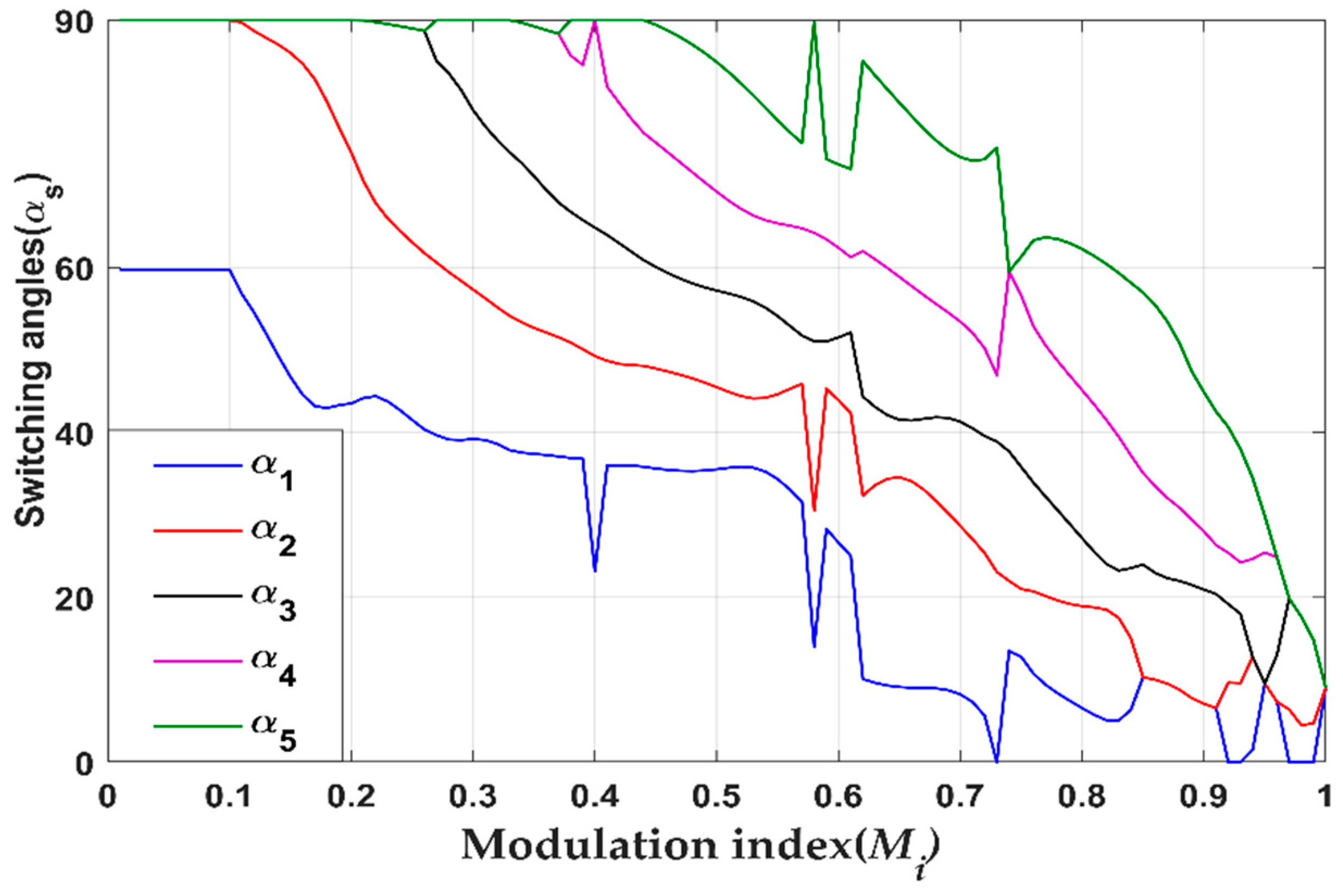
. The switching angles plot versus the modulation index (
Mi) is shown in
Figure 4.
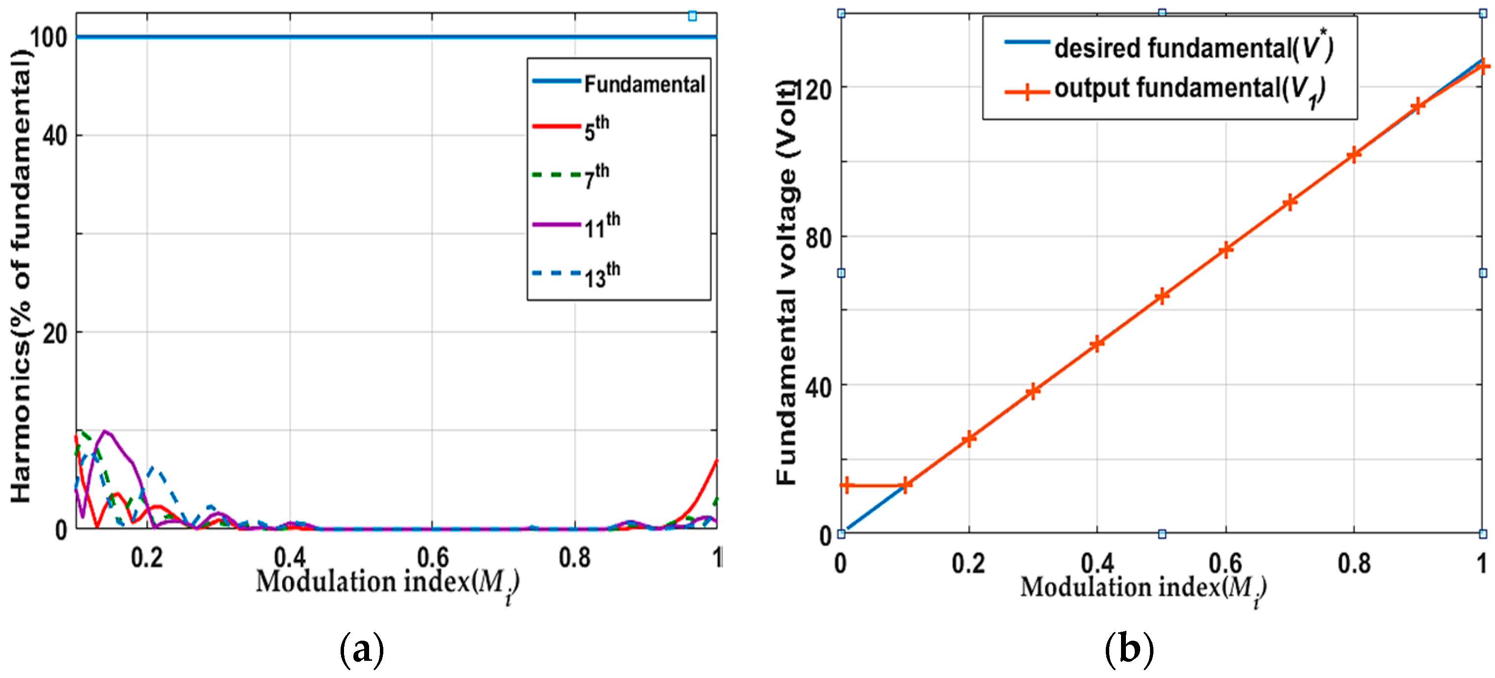
The intended harmonic orders versus
Mi are calculated for the 11-level SHE.
Figure 5a indicates that the low-order harmonics are eliminated within the range of 0.4–0.85
Mi, while maintaining the fundamental level. Concurrently,
Figure 5b shows comparison of fundamental peak voltage between the desired value and the fundamental output from MPA algorithm. Both curves match each other which fulfill the basic SHE principles of controlling in the level of fundamental value.
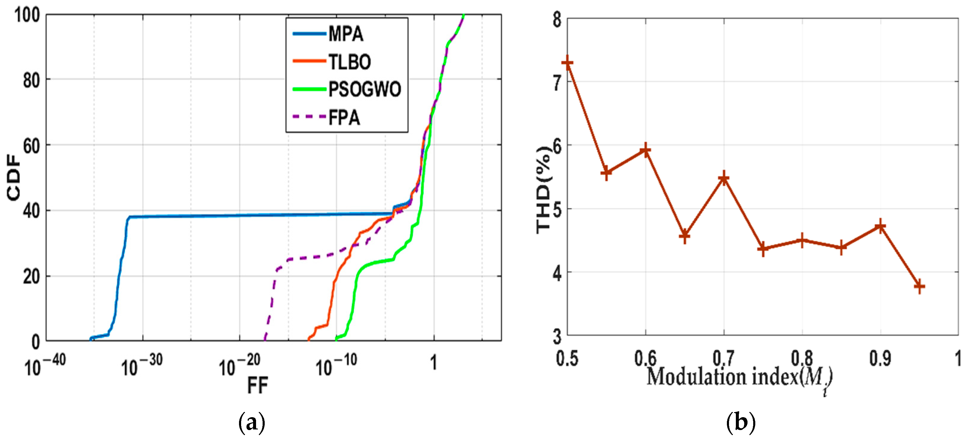
Furthermore, the probability of convergence to the global minimum is evaluated by comparing the cumulative distribution function (CDF) in
Figure 6a of MPA compared with FPA, PSOGWO and TLBO versus FF. The figure verifies the high probability of convergence of MPA. The THD is calculated at different values of the modulation index (
Mi) in
Figure 6b to ascertain the quality of output voltage.
Table 1 shows that for MPA, the THD is low compared to TLBO, FPA, and PSOGWO. This shows that MPA enhances voltage quality, not only harmonics.
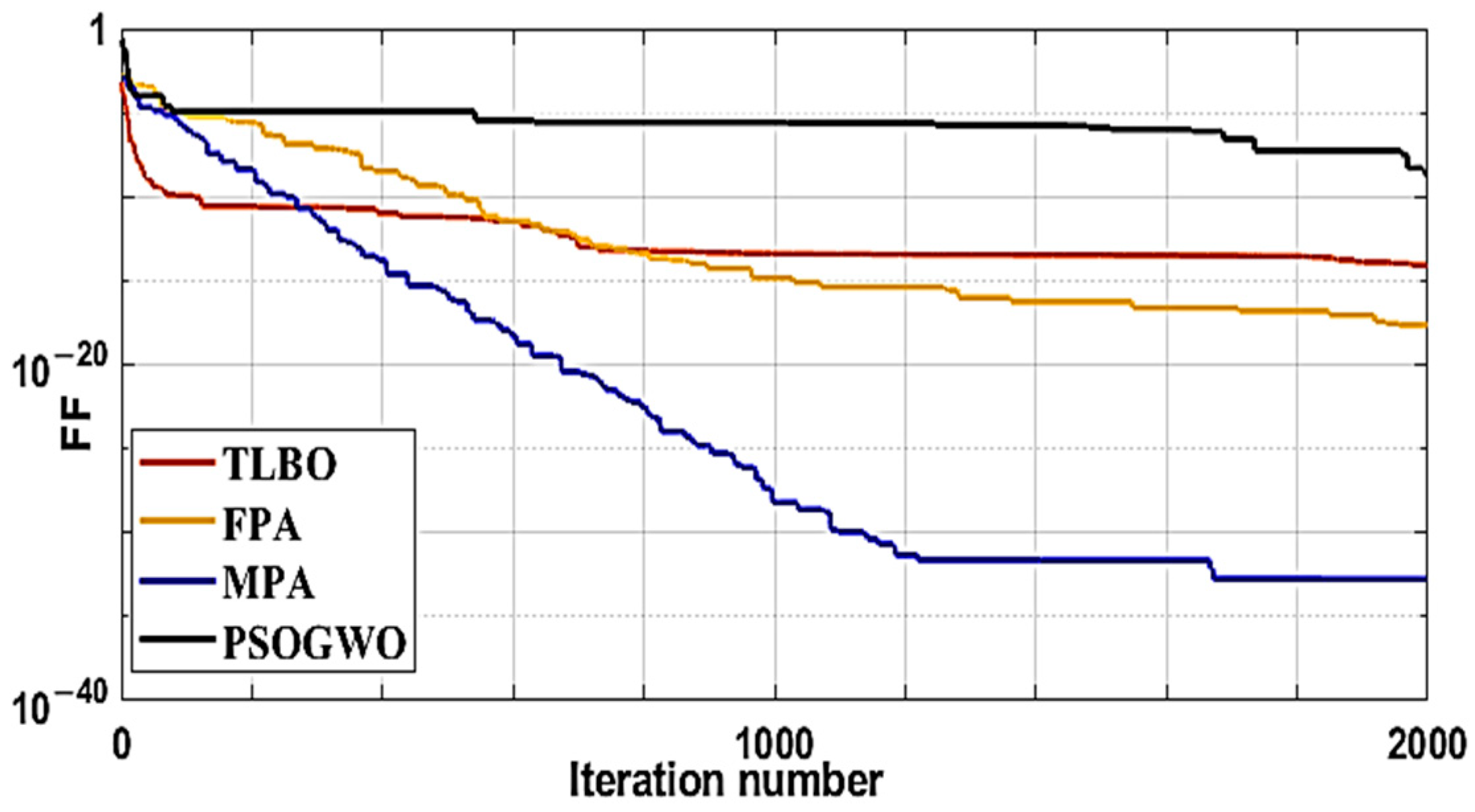
It can be concluded from
Table 2 and
Figure 7 that MPA’s fitness value and convergence rate is better than FPA, TLBO, and PSOGWO algorithms. However, for the same number of iterations, the execution time of MPA is close to FPA and hybrid PSO and less than in TLBO, whereas MPA has a minimum fitness function.
Besides, for certain accuracy such as , the TLBO takes the highest time with 2000 iterations, FPA takes 100 s with 1000 iterations while MPA takes the least time of 55 s with only 200 iterations. PSOGWO does not achieve this accuracy.
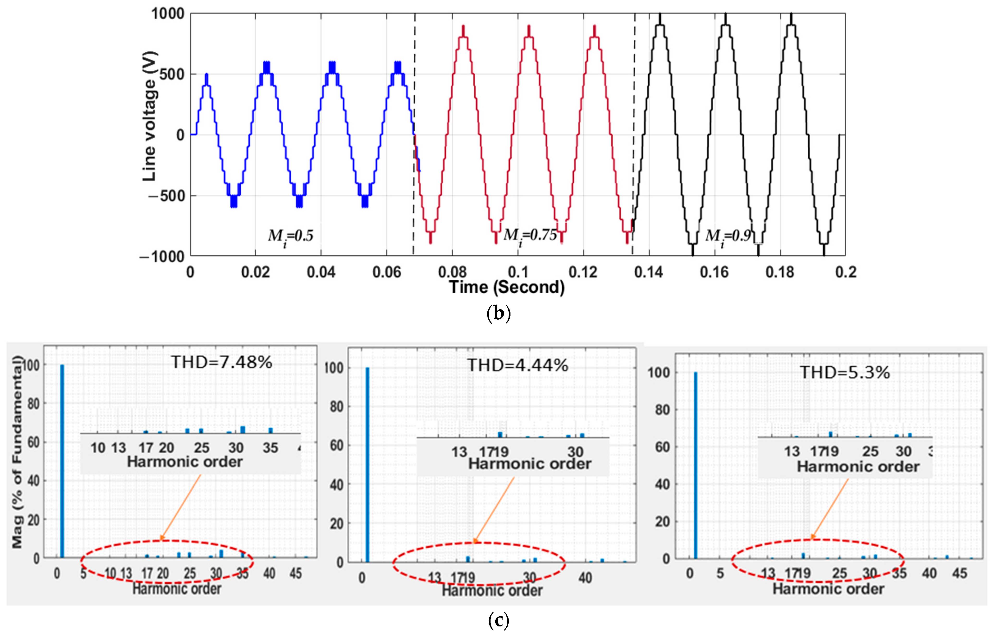
Figure 8 displays phase voltage, line voltage and spectrum analysis under 0.5, 0.75, 0.9 modulation index values. The output waveforms of phase voltage are 11 levels, as seen in
Figure 8b. From
Figure 8c the output voltages exactly match the desired values; the fifth, seventh, eleventh, thirteenth, and third harmonics are eliminated in line voltage. This confirms the correctness of the switching angles and the potency of the SHE technique.
6. Simulation Results for Seven-Level Inverter
Three H-bridge modules are connected in series. The aim of the seven-level inverter is to optimize three switching angles (
α1,
α2,
α3) to eliminate the fifth and seventh voltage harmonics and to achieve the first part of the desired voltage.
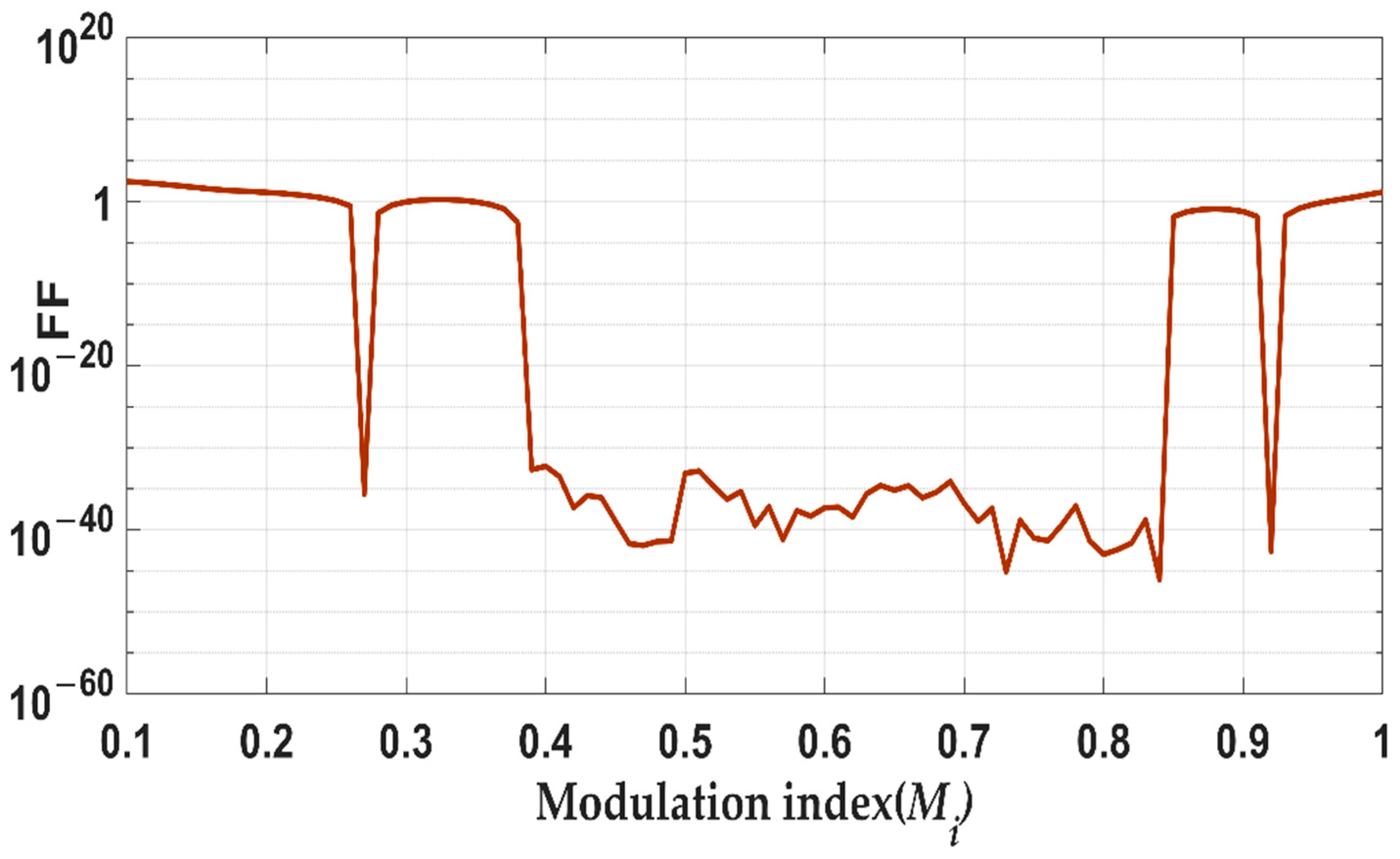
Figure 9 shows the fitness function with modulation index.
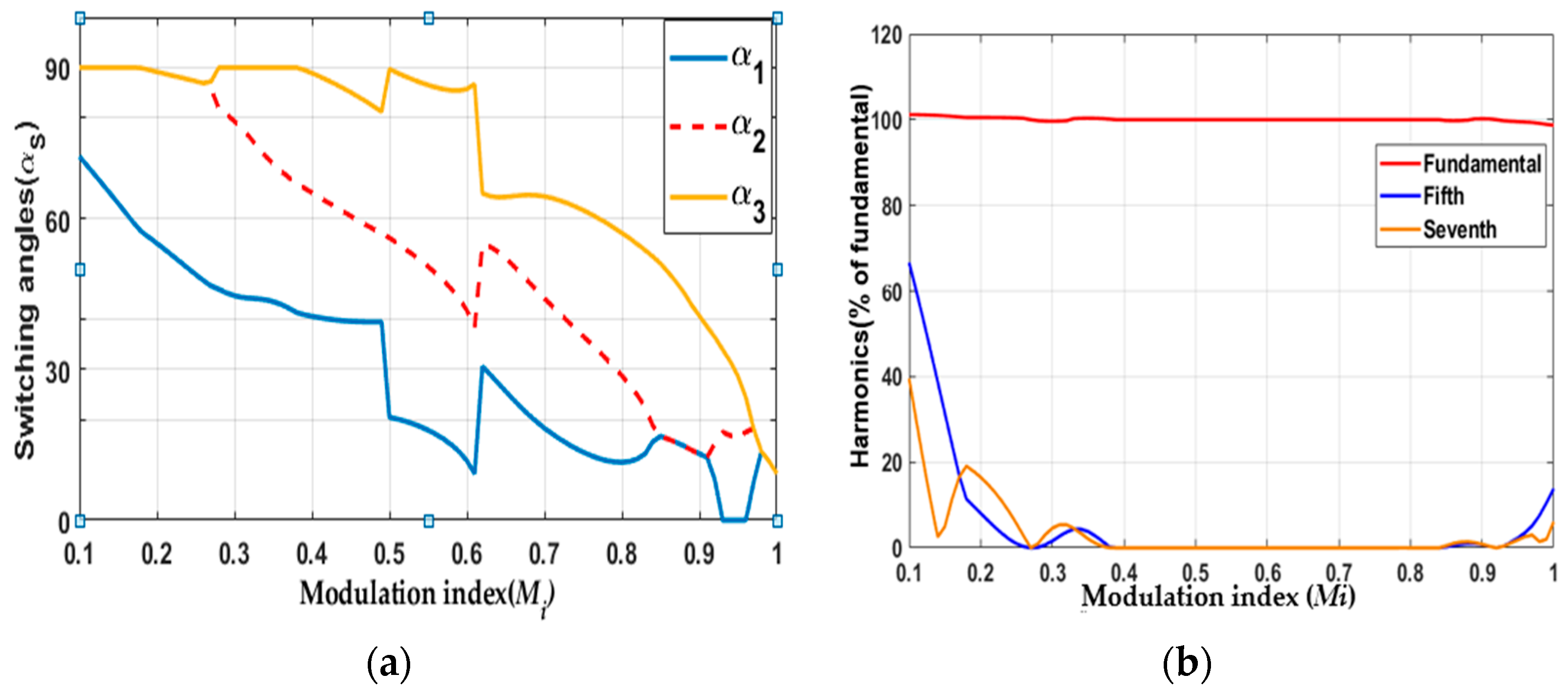
Figure 10 shows three switching angles and the harmonics versus modulation index.
7. Hardware Setup and Experimental Results for Seven-Level Inverter
The simulation results obtained from the proposed MPA algorithm are verified through the scaled-down prototype in the laboratory. A seven-level cascaded H-bridge three-phase inverter shown in
Figure 11 was constructed using IRFP460 MOSFET (Intersil Corporation, Milpitas, CA, USA) (500 V, 20 A) power switch transistor. Three H-bridges in each phase have identical separate DC voltage sources of 36 V. In addition, 50 Hz is the output voltage frequency. Based on the required switching angles that are determined by the MPA algorithm offline. The dSpace DS1104 (dSPACE, Westphalia, Germany) generates eighteen pulses in three phases for all switches. The amplitude of these pulses is insufficient for the MOSFET switch to be driven. So, the 4N37 optocoupler driver (Vishay Telefunken, Malvern, PA, USA) is used to amplify the pulses. The optocoupler also gives insulation between the power section and the control circuit of the dSpace.
The first experiment was performed at modulation index (
Mi = 0.8) for corresponding switching angles in degrees of
,
,
.
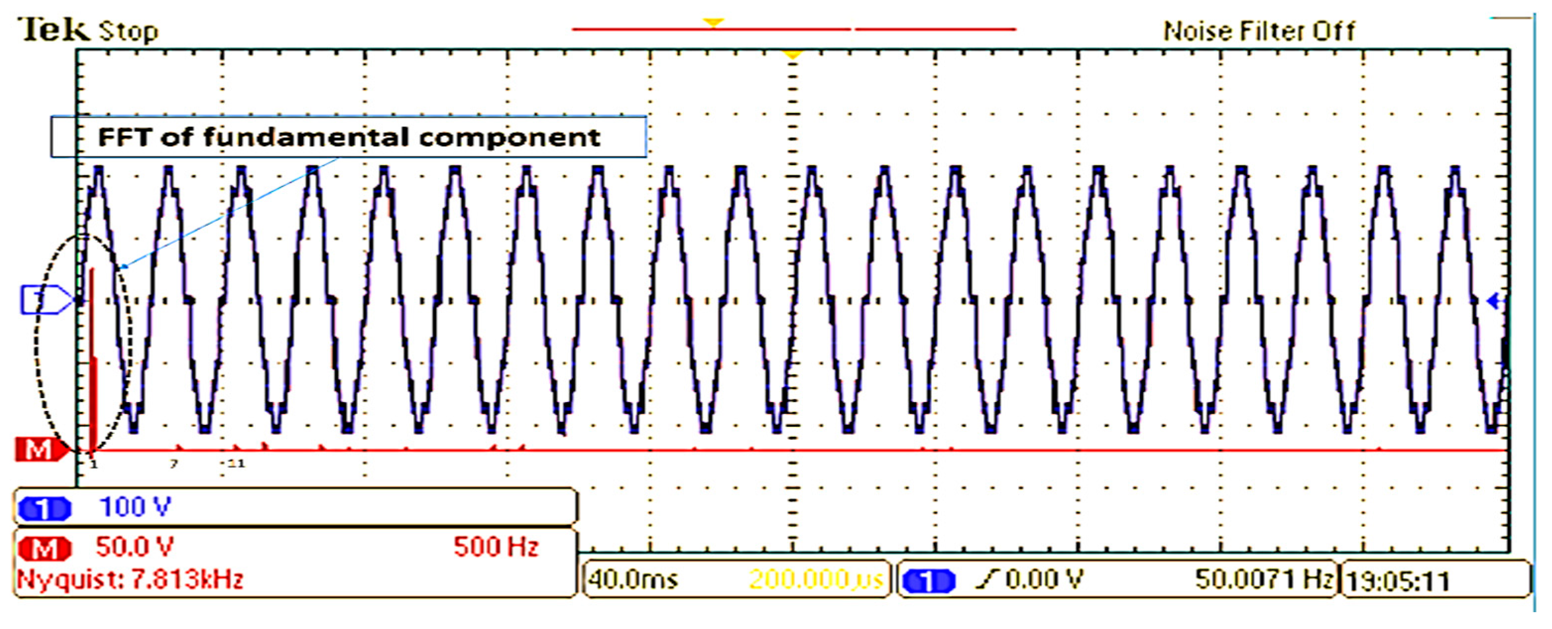
Figure 12 shows the output waveform of two phases. The line-line voltage (
VAB) is shown in
Figure 13 and the FFT spectrum range with red color shows that the targeted exclusion harmonics are absolutely excluded from the output waveform.
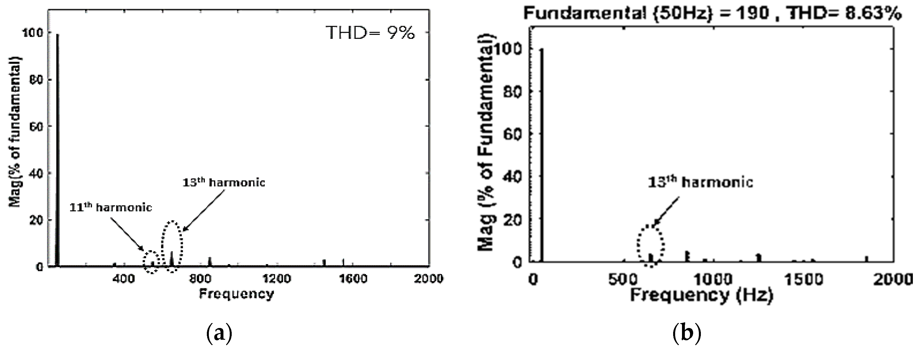
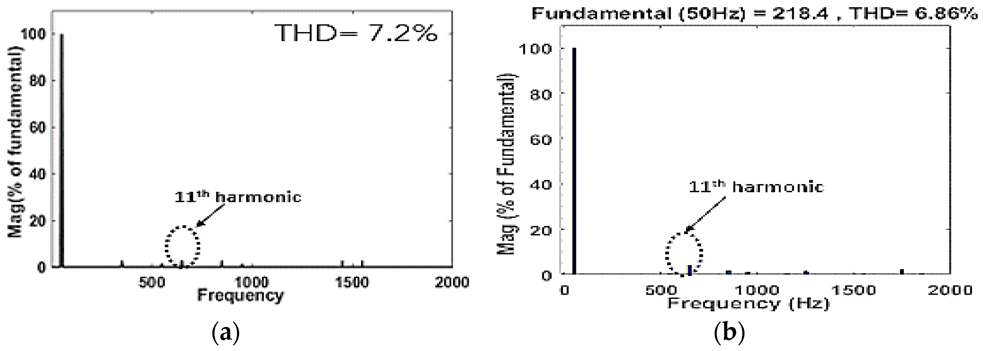
Figure 14 displays the experimental and simulated frequency spectrum of line voltage for
Mi = 0.8. It shows the elimination of fifth and seventh harmonics. In experimental results, the first harmonic is 11th, and its magnitude is 3% of the fundamental component. THD is approximately equal for simulated and experimental results.
The second experiment was performed at modulation index (
Mi = 0.92) for corresponding switching angles in degrees of
,
,
. In
Figure 15, the line-line voltage (
VAB) is shown and its FFT spectrum is in red.
Figure 16 displays the experimental and simulated frequency spectrum of line for
Mi = 0.92. It shows the elimination of fifth and seventh harmonics. In experimental results, the first harmonic is 11th, and its magnitude is 3% of fundamental. THD is approximately equal for simulated and experimental results.
8. Power Losses Analysis
The most important metric in any inverter efficiency calculations is the power loss. The largest power loss occurs in the power switches. In addition to the inverter efficiency, knowing the power loss and the heat dissipated is important for designing the correct heat sink. Total power losses in semiconductor power switches are generally divided into static loss and dynamic loss. The static loss includes loss of conduction (on-state power losses) and loss of cut-off. The dynamic loss includes turning on and failure on turn-off. The most important losses that must be calculated in the power switches are the switching loss (
PSw), conduction loss (
Pcond), and the blocking (
Pblocking). It is important to note the blocking losses due to leakage currents, but they can typically be ignored. However, the switching losses are negligible. The massive drop of the switching losses in staircase MLI inverter devices is a result of the process of the on and off switch during one fundamental period [
34]. The switching device used in the MLI is Si-MOSFET.
8.1. Conduction Losses
The MOSFET conduction power losses (
Pcond) can be estimated using a MOSFET-approximation of the drain to source on resistance (
) [
35].
, are the root mean square of drain to source voltage and drain current. can be obtained from MOSFET datasheet as it is a function of drain current, junction temperature (Tj) and gate to source voltage (VGS).
The instantaneous MOSFET conduction power is given by Equation (25)
The average conduction losses can be expressed as follows.
is the on-state period and
is the phase angle.
The conduction loss of a body diode
can also be determined based on their resistance dynamics (
Ron, Diode), and the diode threshold voltage
as follows:
8.2. Switching Losses
Switching losses exist because there is no immediate transition from on-state to off-state and vice versa. Both the current flow and the voltage through the switch become considerably higher than zero across the transition time, resulting in substantial instantaneous power losses [
36].
During turn on interval the energy dissipated.
where
: Turn on cross over interval.
: energy dissipated during turn on interval.
When the MOSFET is turning off the energy dissipated.
The total energy during turning on and off is:
The switching losses had a linear relation to the switching frequency and the switching current. The general average losses from swapping can be expressed as follows:
9. The Simulation Model for the Loss Estimation
Conduction and switching losses are modeled using the PLECS thermal model for the MOSFET switch.
The switches of H-bridge inverter are all IRFP460-power MOSFET using its thermal model. Main switch parameters are listed in
Table 3 [
37].
The losses of each device are measured in the PLECS simulation model by the real operating conditions and thermal model from the MOSFET datasheet of the three-phase seven-level MLI circuit and the overall average conduction loss and the average switching loss of the device are estimated. This makes it possible for the dynamic and static characteristics of the switching devices to be closer to realistic results.
The power loss of all twelve switching devices for each leg of the CHB-MLI inverter is the same. The average conduction and switching loss for three legs are then obtained as follows.
Using the angles obtained from the proposed MPA in
Section 6.
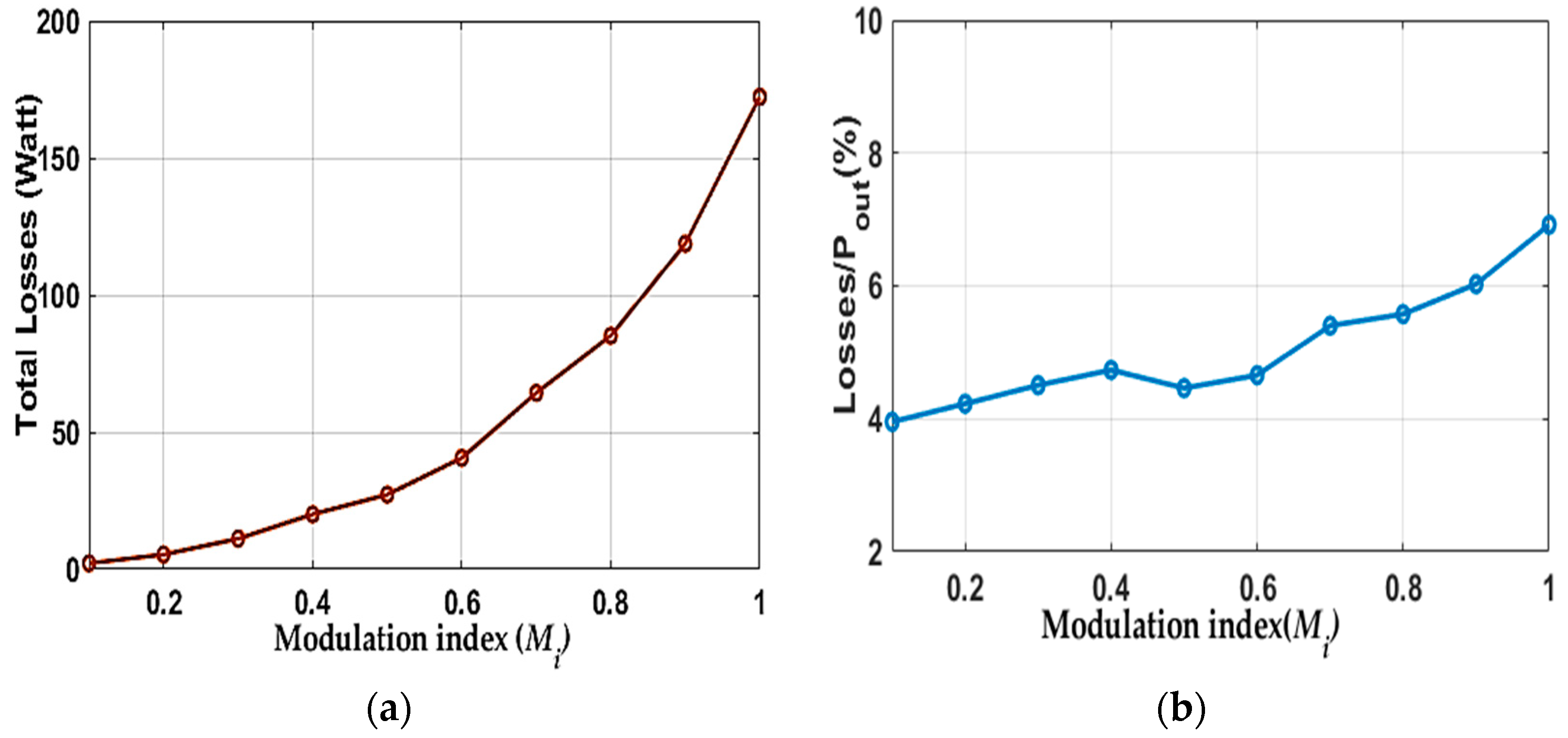
Figure 17 indicates the influence of the change modulation index on the overall power loss of three phases in percent of output power at
Vdc = 100 V and inductive load (
R = 50 Ω,
L = 10 mH). The total loss is between 4%–6.5% of the output power, which indicates the high efficiency of the designed inverter. The power losses increase as the modulation index value increases.
The load has an impact on the inverter total losses. The losses are measured at different load values (RL = 40 Ω, Losses = 333 W), (RL = 50 Ω, Losses = 173 W), (RL = 60 Ω, Losses = 107 W). The inductor values do not have much effect on the values of losses.
The main source of the conduction losses in the designed inverter is the MOSFET on- resistance (
). It can be minimal if lower on-resistance is used. In addition, SiC MOSFET modules can be using the proposed algorithm with minimum loss and maximum output power but with higher cost [
38].
10. Heat Sink Design
The equivalent thermal network cell of one H-bridge cell is shown in
Figure 18.
where
: Thermal conduction resistance between junction and case.
: Thermal conduction resistance between case and heatsink.
: Thermal conduction resistance between heatsink and ambient medium.
: The ambient temperature (= 25 °C)
: The heat sink temperature
: The power loss in each half bridge; can be found from power model.
: The total power loss for one leg
can be considered between 60 °C–120 °C.
Junction temperature can be deduced from Equation (37)
From the data sheet of Si-MOSFET module thermal resistance of junction ( = 0.45 °C/W) and ( = 40 °C/W).
Each leg in the inverter has a heatsink.
The heat sink volume can be determined by Equation (39). It was found from the quantity of separate extruded, naturally cooled heat sinks with the thermal resistance of heat sinks, obtained from the curve fitting [
39].
Heatsink volume calculations and total power loss for one leg of the designed inverter with the temperature of heatsink are presented in
Figure 19. The losses are measured at
Vdc = 100 V and the inductive load of
R = 10 Ω,
L = 10 mH.
11. Conclusions
Different algorithms have been investigated in a three-phase 11-level cascaded H-bridge. MPA is tested in comparison with FPA, TLBO, and PSOGWO. The simulation results prove that high accuracy, high probability of convergence, and low THD for MPA over other algorithms. The experimental results of the three-phase seven-level inverter validate the influence of the proposed algorithm to nearly eliminate fifth and seventh harmonics behind triple harmonics.
For the Si MOSFET switches used in the designed inverter, the appropriate power loss equations have been derived. The switching loss and conduction loss of the Si-MOSFET switches devices used in the designed inverter with the MPA algorithm are obtained. The results are based on experimental data and a thermal model from PLECS. The switching loss is very small in the mW range and minimal because of using the fundamental switching modulation technique. In addition, the total loss, and the loss in percentage of output power is measured with different modulation index at Vdc = 100 V. The measurements show that losses are between 4% and 6.5% of output power. These losses may decrease when using other types of switches such as Si-MOSFET with lower RDS-on or SiC-MOSFET. There is an increase in power losses with the increase in the modulation index, so, the heat sink is designed for (Mi = 1). These algorithms can also be applied to various types of MLI topologies, and the optimal design can be found according to application and power requirements.


