Article

Optical Code Construction of 2D Spectral/Spatial BIBD Codes for SAC-OCDMA Systems

1
Department of Applied Sciences, University of Quebec in Chicoutimi (UQAC), Chicoutimi, QC G7H 2B1, Canada
2
Department of Electrical and Computer Engineering, Laval University, Québec, QC G1V 0A6, Canada
3
Electrical Engineering Department, College of Engineering at Wadi Aldwaseer, Prince Sattam Bin Abdulaziz University, Al-Kharj 16278, Saudi Arabia
4
Electronics and Micro-Electronics Laboratory (E. μ. E. L), Faculty of Sciences, University of Monastir, Monastir 5000, Tunisia
5
Department of Electrical Engineering, Jalozai Campus, University of Engineering and Technology, Peshawar 23431, Pakistan
*
Author to whom correspondence should be addressed.
Appl. Sci. 2021, 11(2), 783; https://doi.org/10.3390/app11020783
Submission received: 7 December 2020 / Revised: 5 January 2021 / Accepted: 10 January 2021 / Published: 15 January 2021

Abstract

:
Optical code division multiple access (OCDMA) shows limitations in terms of the inefficient bandwidth utilization and low spectral density with one-dimensional (1D) codes. To overcome these limitations, a novel design is presented using a two dimensional (2D) spectral/spatial multiwavelength coding scheme. The proposed code is constructed using a 1D balanced incomplete block design (BIBD) technique. Theoretical and analytical results indicate that the proposed code provided improvement in the number of simultaneous users, code construction, and cross-correlation and minimized noise. Moreover, the bandwidth requirements can be minimized, and it can provide flexibility in addressing code sequences. Finally, results were compared with existing spectral-spatial 2D codes such as diagonal eigenvalue unity (DEU) and 2D diluted perfect difference (DPD). It was observed that the 2D-BIBD code fulfilled optical transmission needs with minimum effective source power (Psr = −27.5 dBm) when compared to 2D-DEU (−26.5 dBm) and 2D-DPD (−25.5 dBm) codes. Overall, our results suggested that the performance of BER for the proposed code was 72% and 22% higher than the existing 2D-DPD and 2D-DEU codes, respectively.

1. Introduction

The main parameters used to measure performance of Optical code division multiple access (OCDMA) system are available bandwidth, signal-to-noise ratio (SNR), and the cross-correlation between coded signature sequences [1]. Major development in the optical access technology can assure increased bandwidth and improved data rates with higher numbers of supported users [2]. In OCDMA, a number of coding methods are available: frequency hopping [3,4], time spreading [5,6,7], spectral polarization [8], spatial and spectral amplitude coding (SAC) [8]. In all of these, SAC has gotten more attention in recent years as codes with fixed in phase cross-correlation (IPCCs) and zero cross-correlation (ZCC) properties are used. Such codes with efficient detection schemes can effectively suppress the multiple user interference (MUI) among codes [9].
Wavelengths based on user data can be chosen using low cost fiber Bragg grating (FBG) filters for encoding purposes in case of SAC based OCDMA system. Additionally, incoherent optical sources such as white light LEDs make its implementation low-cost when compared to existing data encoding techniques [10]. However, 1D codes used in SAC systems have some drawbacks such as large code length resulting in complex code construction and restrained code cardinality and bandwidth. This limits its scope only for short distance communication, specifically for fiber to the home (FTTH) and local area network (LAN) applications [11,12]. Sun and Yang [13] presented 2D optical orthogonal codes (OOC), with increased cardinality and good auto and cross-correlation properties for OCDMA systems.
In particular, 1 dimension (1D), 2 dimensions (2D), and 3 dimensions (3D) are the coding dimensions in OCMDA schemes [14]. 1D codes are bandwidth inefficient due to their large code length because they are governed by optical broadband source (BBS) which also limits the number of supported users [15]. The code length is inversely proportional to the number of users, therefore, fewer users can be accommodated. In addition, to efficiently encode the optical spectrum, noncoherent optical sources with relatively high chip width and FBGs are used resulting in a large bandwidth. Conventional SAC-OCDMA systems using 1D codes limit the suppression of intensity noise (IN). Therefore, a coding scheme with optimal length and ideal cross correlation code properties is desirable because it can provide enhanced system capacity in terms of data rate and code cardinality. For these reasons, 2D codes have been proposed and designed by combining two different dimensions of CDMA.
2D codes with dimensions (spectral/time, spectral/spatial, and time/spatial) lead to efficient bandwidth utilization with better performance in terms of increased users due to spectral density expansion at the cost of high-speed electronic devices [16]. Moreover, 2D coding techniques, especially based on wavelength/time (W/T) and spectral/spatial S/S, result in higher transmission capability and more flexibility as compared to 1D and 2D time/spatial (T/S) coding approaches [17]. Further, reported 2D codes can be divided into two types: conversion of 1D sequences to 2D codes [17] and hybrid sequences in which one type of code sequence is crossed with another in order to increase the cardinality as well as to improve correlation properties [18,19]. Thus, as a trade-off among different performance characteristics, different coding approaches being studied can be used for specific applications. Kandauci et al. [18] presented construction of 2D W/T hybrid code (optical complementary code and balanced incomplete block design (BIBD) zero cross-correlation codes) which is constructed using BIBD design. The proposed code showed ZCC properties and results indicated an increase in the number of supported users. For SAC based OCDMA systems, novel 2D hybrid code is introduced, and performance is compared with existing 2D M-matrices code in [19].
Previous studies show that 2D code families constructed using prime numbers show MAI effects due to shorter temporal length and larger correlation. In the OCDMA environment, 2D-BIBD codes performed better than 2D extended set prime code families due to their easy code construction, optimum temporal length, quantity of users, and good auto and cross-correlation properties [20]. For example, Djebbari et al. [21] presented a new 1D-BIBD code construction based on zero cross-correlation code (ZCC) properties. The ZCC (C, w) code is a family of binary sequences of constant Hamming-weight w and length C. The presented ZCC codes have a size of C     N   ×   w   +   1 , where C refers to any prime number and N is the number of users. The proposed code construction method is easier compared to the existing ones. These codes are further implemented in a SAC-OCDMA system environment.
Previously, 1D codes showed limited system performance in terms of code cardinality due to the restricted bandwidth of the source. However, 2D spectral/spatial (S/S) codes were able to solve this problem by extending the number of coded sequences in the spatial domain in which every frequency component is divided according to the spatial code of a particular user. So far, to the best of our knowledge, the 2D-BIBD code based on the spectral spatial approach along with conversion of 1D-BIBD to 2D-BIBD and its implementation in SAC environment is not reported in literature.
Further, Yang et al. [22] proposed a 2D maximal area matrices code (2D MM) constructed from a 1D matrices code family. The system performance was not significant due to high MAI among user codes. Similarly, Kadhim et al. [23] showed that the 2D multidiagonal (MD) code can be derived from 1D MD code using ZCC code properties. Abdullah et al. [24] showed that the 2D modified double weight code (MDW) can be derived from 1D MDW using an S/S coding approach.
In another study, 2D spectral/spatial diluted perfect difference (DPD) code showed interference cancellation properties as well as PIIN noise suppression abilities due to its design dependence on perfect difference set and dilution approach [25]. Moreover, Najjar et al. [26] discussed the construction of a 2D diagonal eigenvalue unity (DEU) code using an S/S coding approach with minimum cross-correlation and observed that the cardinality was increased when compared to existing 2D-DPD and 1D DEU codes. The advantage of BIBD is that their code families exist for prime and nonprime code weight values. Moreover, they can be designed for any code length (L), code weight (w), and cross-correlation ( λ c ). Therefore, this study’s objective was to design and develop a novel 2D-BIBD code using a spectral/spatial coding approach, which can support a higher number of users in the OCDMA environment.
The proposed code is constructed using a 1D balanced incomplete block design (BIBD) technique. It is designed and implemented for spectral amplitude coding (SAC) based OCDMA networks and constructed using a 1D-BIBD code matrix. This matrix includes the estimation of the weight values and the number of users, which corresponds to code length. Due to its effective code design approach, the proposed code family yields large cardinality with optimal code length. Further, initial blocks are derived based on primitive elements, and by modulo addition of initial blocks, remaining blocks in the design are obtained. Next, the 1D code matrix is transformed into a 2D code using the cyclic shifting of the 1D-BIBD code set matrix. The 2D-BIBD code development algorithm is presented along with the 2D-BIBD code-based SAC OCDMA. The system performance is analyzed using Gaussian approximation in the presence of various noise sources.
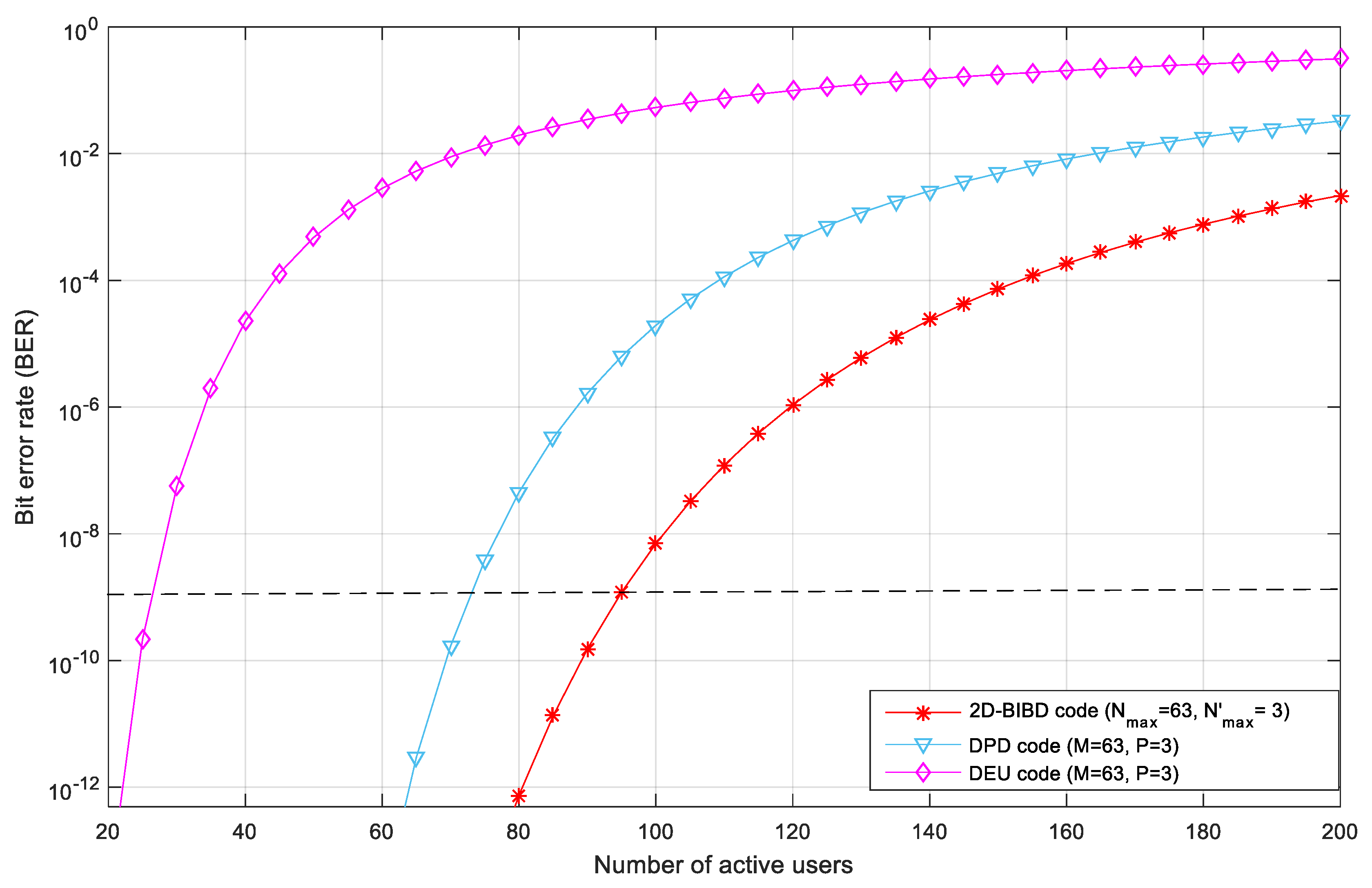
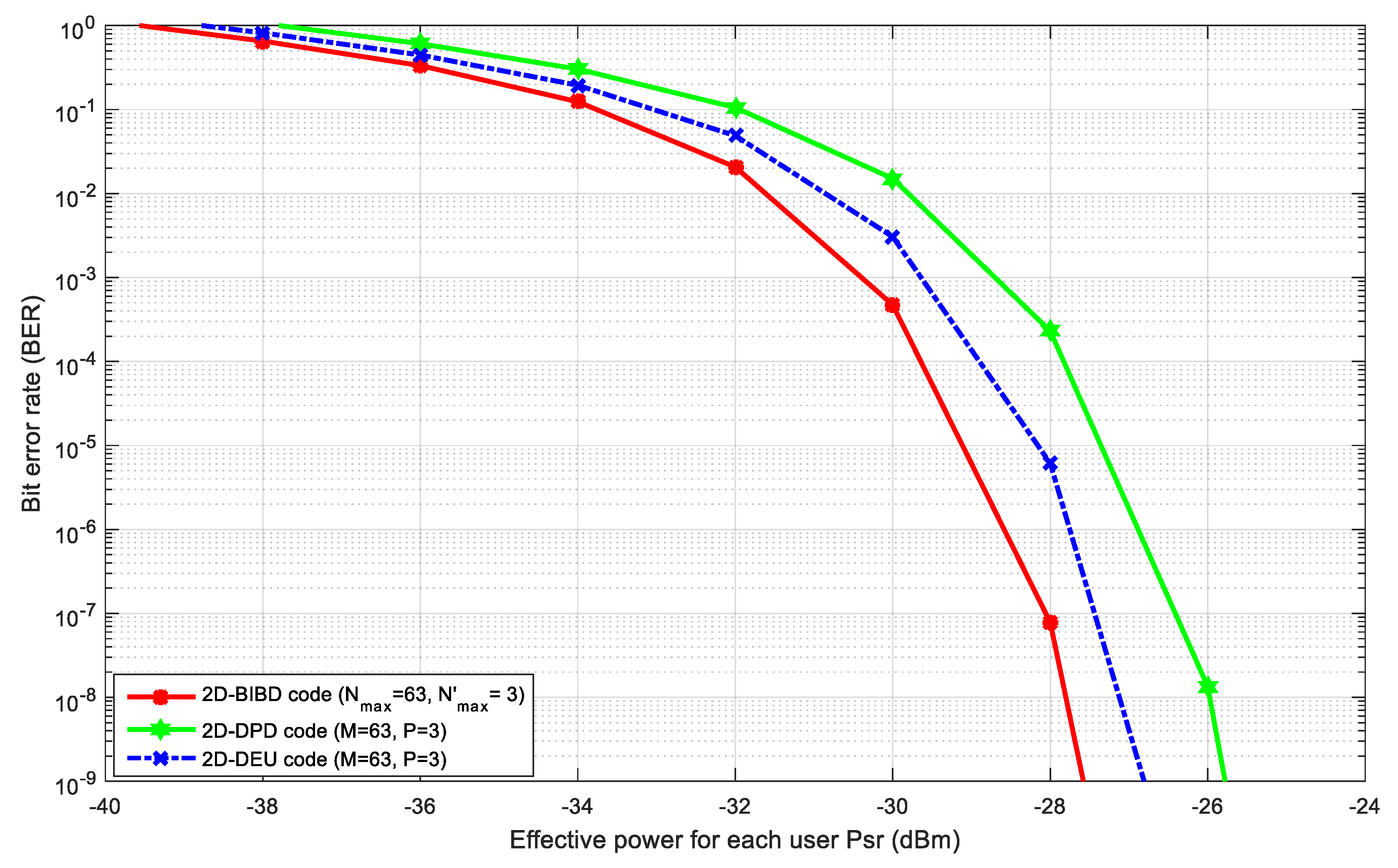
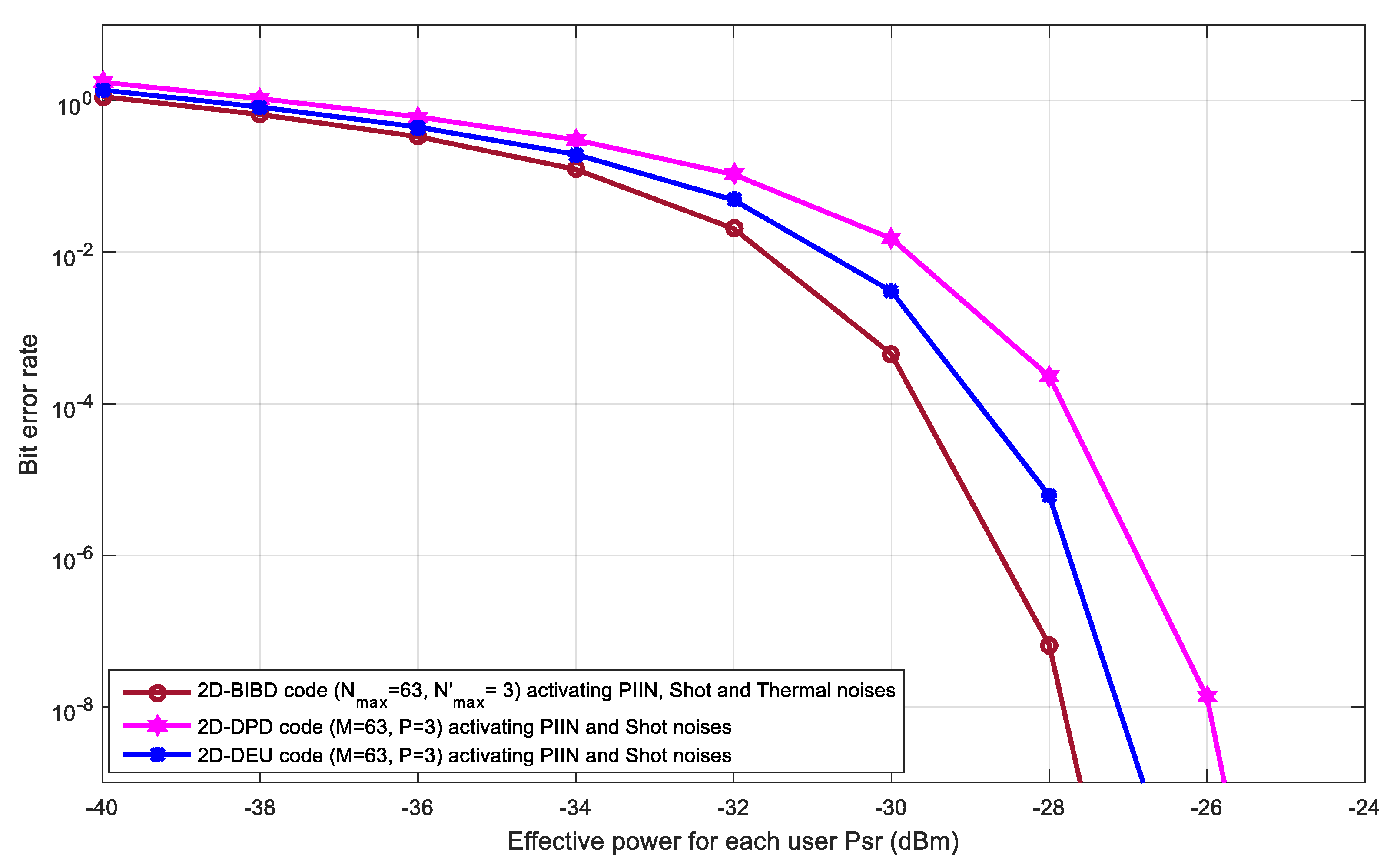
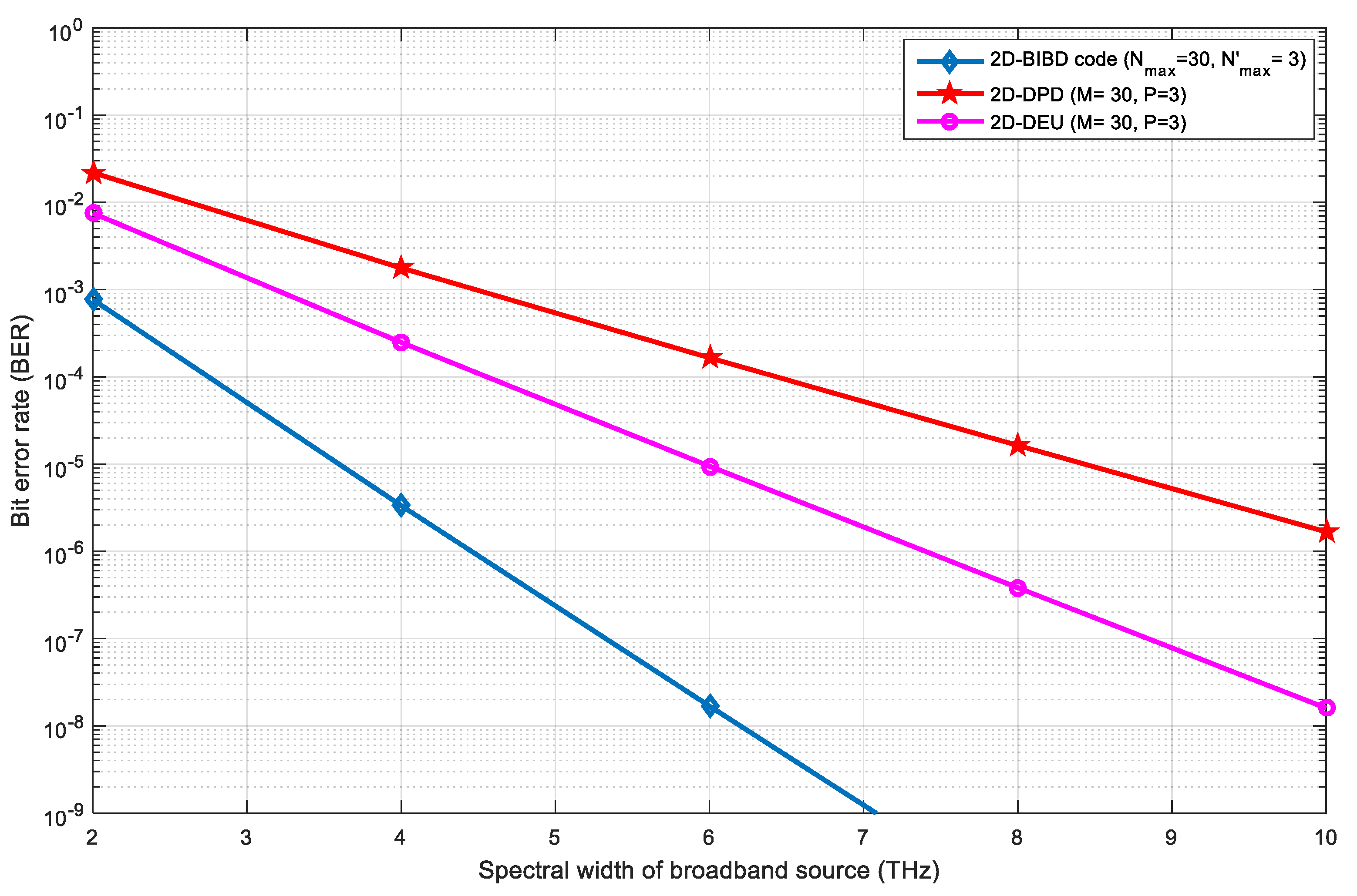
We derived BER performance expressions using Gaussian approximations considering the effects of PIIN, shot, and thermal noises. 2D-BIBD code performance is compared with existing 2D-DPD and 2D-DEU codes. Simulations are carried out by setting different fiber related parameters and activating wavelength-dependent nonlinear effects such as cross-phase modulation, four-wave mixing, and self-phase modulation at different data rates. We expected that the proposed code could provide better cross-correlation properties with increased cardinality. A simple code construction method and a low-cost receiver architecture compared to existing 2D OCDMA codes were introduced within the proposed model.
The contributions of this paper are the following:
  • Design of novel 2D-BIBD code.
  • Analytical and simulation validation of the 2D-BIBD numerical model.
  • Accommodation of many active users with a high bit rate.

2. 2D-BIBD Code for SAC–OCDMA Systems

The construction of a 1D-BIBD code is based on a combinatorial theory that uses cyclic shift method and Galois field for code construction. A BIBD code is represented as ( L ,   w ,   λ c ,   λ a ), where L stands for code length or total time chips in a code-word, w represents the weight of the code (i.e., time chips having value 1), λ a   i s   the autocorrelation value, and λ c   is the maximum cross-correlation value.
The fundamental equation which governs the BIBD code is given in Equations (1) and (2) [13].
B × K = V × R
R × ( K 1 ) = λ × ( V 1 )
B represents the total number of blocks and K is the number of elements in one block, which is equal to the weight of the code (w). V is the number of terms that correspond to code temporal length (L), R is the replication of each entry, λ   is the cross-correlation ( λ c ) among signature sequences in a code family.
The design of a 1D-BIBD code consists of two steps: the first step is to design the initial blocks, followed by modulo addition of the initial blocks to get all of the other blocks in a design that is used to reach the second step.
For a code family of N m a x maximum number of users, the length of code L is given as
L = w × ( w 1 ) N m a x + 1
where, w refers to the code weight, and N m a x represents the maximum number of users in the code family or cardinality.
Therefore, the initial blocks for the BIBD code is given as
( α 0   , α 2 N m a x , α 4 N m a x ) ,   ( α 1 ,   α 2 N m a x + 1 , α 4 N m a x + 1 )   , ( α N m a x 1 ,   α 3 N m a x 1 , α 5 N m a x 1 )
Here   α denotes the primitive element of GF(L).

2.1. Construction of BIBD Code Families

The 2D-BIBD code construction is based on a 1D-BIBD code. A 1D-BIBD has a simple code structure, which is illustrated in the following steps.

2.1.1. 1D-BIBD Code Construction

As mentioned above, the code sequences of the BIBD code family are represented as ( L ,   w ,   λ a ,   λ c ) . This construction gives the optimal code cardinality i.e.,
| c | = ( L 1 ) / w ( w 1 )
For example, when L = 13 and w = 3 , c = 2 . This means that the number of users is limited to 2 (i.e., N m a x = 2 ), and a total of 26 codewords can be generated.
The primitive element α for GF(13) is 2. Therefore, the initial blocks for the codes are given as ( 2 0 ,   2 4 , 2 8 ) ( 2 1 , 2 5 , 2 9 ), which corresponds to coded sequences (1, 3, 9) and (2, 6, 5). Using these two codes sets, different users can be assigned, such as the first user (C1 = 1010000010000) and the second user (C2 = 0100110000000). Further, a total of 26 BIBD codewords can be designed by rotating C1 and C2 either left or right.
Table 1 illustrates an example of the code sequence based on two different 1D-BIBD code families. First, 1D-BIBD code is represented by X ( N m a x = 3 and w = 3 ), and the second 1D-BIBD code is represented by Y ( N m a x = 2 and w = 3 ), each having a code length 19 and 13, respectively. Further, a total of 57 and 26 code sequences (i.e., number of users are 57 and 26) can be generated by a cyclic shifting approach.

2.1.2. Proposed 2D Spectral/Spatial BIBD Code

In order for the users to cause minimal interference to other codes, the auto and cross-correlation values must be small so that there will be fewer overlapping chips in the SAC OCDMA system. Optimal OOC codes based on the BIBD construction should have minimum cross-correlation and maximum off-peak auto-correlation.
A cyclic shifting approach can obtain 1D-BIBD code sequences. Further, 2D-BIBD codes are extended or converted from the 1D-BIBD, constructed by using two different code-sets of a 1D-BIBD code family based on previously developed 2D spectral/spatial coding approaches [25]. In addition, 2D-BIBD code sets are entitled by unitary matrices.
To convert 1D-BIBD into 2D-BIBD, we consider following two 1D code sequences: X = [ x 0 , x 1 , . x L 1 ] with [ N m a x = 3 , w 1 = 3 ] and Y = [ y 0 , y 1 , . y L 2 ] with [ N m a x = 2 , w2 = 3], respectively, where L 1 and L 2 are the code lengths which are 19 and 13 for the X and Y code sequences, respectively, and w is the code weight ( w = w 1 = w 2 = 3 ).
The resulting 2D-BIBD code can be expressed as:
C g , h = Y g T X h
where,   X h and Y g T are the h t h and g t h code sequences of the spectral ( X ) and spatial ( Y ) code sequence, respectively, whereas   g   =   0 ,   1 ,   ,   N m a x 1 and   h   =   0 ,   1 ,   ,   N m a x 1 .
The resulting code size of the 2D-BIBD code is N m a x N m a x , where N m a x and N m a x are the code sizes (number of code matrices/users per code sequence).
An example of a 2D-BIBD code development using two 1D-BIBD code sequences, belonging to two different code families is illustrated in Table 2. X 1   = ( 1 ,   7 ,   11 ) ,   X 2 = ( 2 ,   3 ,   14 ) , and X 3 = ( 4 ,   6 ,   9 ) will be the resulting three blocks of the 2D-BIBD code matrix and Y 1   = ( 1 , 3 , 9 ) and Y 2   = ( 2 , 5 , 6 ) will be the resulting two other block codes. Table 2 states the allocation of wavelengths and optical couplers (CP) for six users ( U 1 , 1 ,   U 2 , 1 ,   U 3 , 1 ,   U 1 , 2 ,   U 2 , 2 ,   a n d   U 3 , 2 ) using X 1 = 1000001000100000000, X 2   =0110000000000100000, X 3 = 0001010010000000000 and Y 1 = 1010000010000, Y 2 = 0100110000000, respectively.
The construction process of the proposed code is shown as Algorithm 1. The BIBD coding algorithm is derived using two BIBD blocks. The BIBD algorithm has four specified inputs:   N m a x , N m a x and the set numbers of Wi, while the output of the algorithm is the C g , h   generated codes for N m a x N m a x users. The proposed design of the 2D-BIBD coding technique includes six steps to determine the N m a x N m a x codes:
  • Determining the total code length (line 1–line 2). The proposed 2D-BIBD codes can support a total of N m a x × N m a x users with code length of L 1 × L 2 . For example, when (w1,   N max ) = (3,3), L 1   = 3 × ( 3 1 ) 3 + 1 resulting in 19 as the code length for the spectral dimension, likewise for L 2 .
  • Selecting two prime numbers over GF( L i ) (line 3–line 4). α 1 and α 2 denote the primitive elements of GF( L 1 ) and GF( L 2 ), respectively. For GF( L 1 = 19 ), α 1 = 2 is selected as a prime number for the spectral dimension.
  • Generating the first spectral and spatial BIBD blocks (C1 and C2) by using Equation (5) (line 5–line 13). For ( α 1 , L 1 ) = (2,19), the first selected 1D-BIBD block C1 = ( ( α 1 1   m o d   L 1 ) 1   ,   ( ( α 1 2 × 3 + 1   m o d   L 1 ) 1   ,   ( α 1 4 × 3 + 1 m o d   L 1 ) 1 , )   resulting in (1, 14, 3) which represents the positions of 1s. Likewise for the spatial dimension.
  • Generating the X h matrix for the BIBD spectral codes (line 15–line 18). The 1D-BIBD spectral codes are represented by a set of sequence designed by rotating right C1 by 1. When C1 is represented by (1, 3, 14), the generated code for the second user becomes (2, 4, 15).
  • Generating the Y g matrix for the BIBD spatial codes (line 20–line 23). The 1D-BIBD spatial codes are represented by a set of sequences designed by rotating right C2 by 1. When C2 is represented by (2, 5, 6),
  • the generated code for the second user becomes (3, 6, 7).
  • Resulting 2D-BIBD codes are designed by using X h , Y g   and   Equation (6) (line 25–line 26).
Algorithm 1. Proposed 2D-BIBD Spectral/Spatial code for OCDMA systems.
Input:   N m a x ,   N m a x //number of served users
Input:   w i = { w 1 ,   w 2 }   / /     w i represents weight of spectral and special generated codes
Output:   C g , h = Y g T X h // C g , h is 2 D   B I B D matrix CODE
1.  Define     L 1 = w 1 × ( w 1 1 ) N max + 1 // L 1 represents spectral code sequence length
2.  Define     L 2 = w 2 × ( w 2 1 ) N m a x + 1 // L 2 represents spatial code sequence length
3.  Define   α 1 / /   primitive   element   of   GF ( L 1 )
4.  Define   α 2 / /   primitive   element   of   GF ( L 2 )
5.  Define   X / /   X   is   a   N m a x L 1 matrix spectral codes
6.  Define   Y / /   Y   is   a   N m a x L 2 matrix spatial codes
7. BIBD blocks generation
8.  X 0 ( L 1 1   d o w n t o   0 ) = ( o t h e r s = > 0 ) ;
9.  Y 0 ( L 2 1   d o w n t o   0 ) = ( o t h e r s = > 0 ) ;
10.  For   i   =   0   to     w 1 1 loop
 10.1.  X 0 ( ( α 1 2 i N m a x + 1   m o d   L 1 ) 1 ) = 1 ;
11. End for
12.  For   i   =   0   to     w 2 1 loop
 12.1.  Y 0 ( ( α 2 2 i N m a x + 1 m o d   L 2 ) − 1)=1;
13. End for
14. BIBD spectral codes generation
15.  For   h = 1   to   N m a x 1 loop
16.  X h ( L 1 1   d o w n t o   0 ) = ( o t h e r s = > 0 ) ;
17.  X h = R O R ( X h 1 , 1 ) ;
18. End for
19. BIBD spatial codes generation
20.  For   g = 1   to   N m a x 1 loop
21.  Y g ( L 2 1   d o w n t o   0 ) = ( o t h e r s = > 0 ) ;
22.  Y g = R O R ( Y g 1 , 1 ) ;
23. End for
24. 2D-BIBD codes generation
25.  For   g = 0   to   N m a x 1 loop
 25.1. For h = 0   to   N m a x 1 loop
  25.1.1.  C g , h = Y g T X h
 25.2. End for
26. End for
27. Return C g , h

2.2. 2D-BIBD Code Properties

Four characteristic matrices were introduced to design the transmitter and receiver module through C(d), where   d [ 0 , , 3 ] . They will be used to evaluate the cross-correlation characteristics of the 2D-BIBD code.
C g , h ( 0 ) = Y g T   X h   C g , h ( 1 ) = Y g ¯ T X h C g , h ( 2 ) = Y g T X h ¯ C g , h ( 3 ) = Y g ¯ T X h ¯
where X h ¯   and   Y g ¯   are the complementary of X h and Y g . The 2D-BIBD code C g , h is represented by set of elements C i , j where i   varies   from   ( 0 , , L 2 1 ) and j varies   from   ( 0 , , L 1 1 ) .
The cross-correlation for 2D-BIBD coding technique between C g , h and C ( m ) is represented as:
R g , h ( d ) = i = 0 L 2 1 j = 0 L 1 1 c i , j ( d ) × c i , j ( g , h )
where c i , j ( d )   and c i , j ( g , h )   are the (i, j)th elements of C(d) and Cg,h, respectively.
Based on Equations (7) and (8), 2D-BIBD codes cross-correlation values are listed in Table 3.
We identified that R(1)(g,h), and R(3)(g,h) values showed no role in constructing the new correlation function, which resulted in an easier MUI cancellation process. Therefore, a new cross-correlation function can be represented as follows (Table 3):
R g , h ( 0 ) R g , h ( 2 ) ( w 1 1 ) = { w 1 w 2         ,   f o r   g = h = 0 0             o t h e r w i s e                          

3. 2D-BIBD System Description

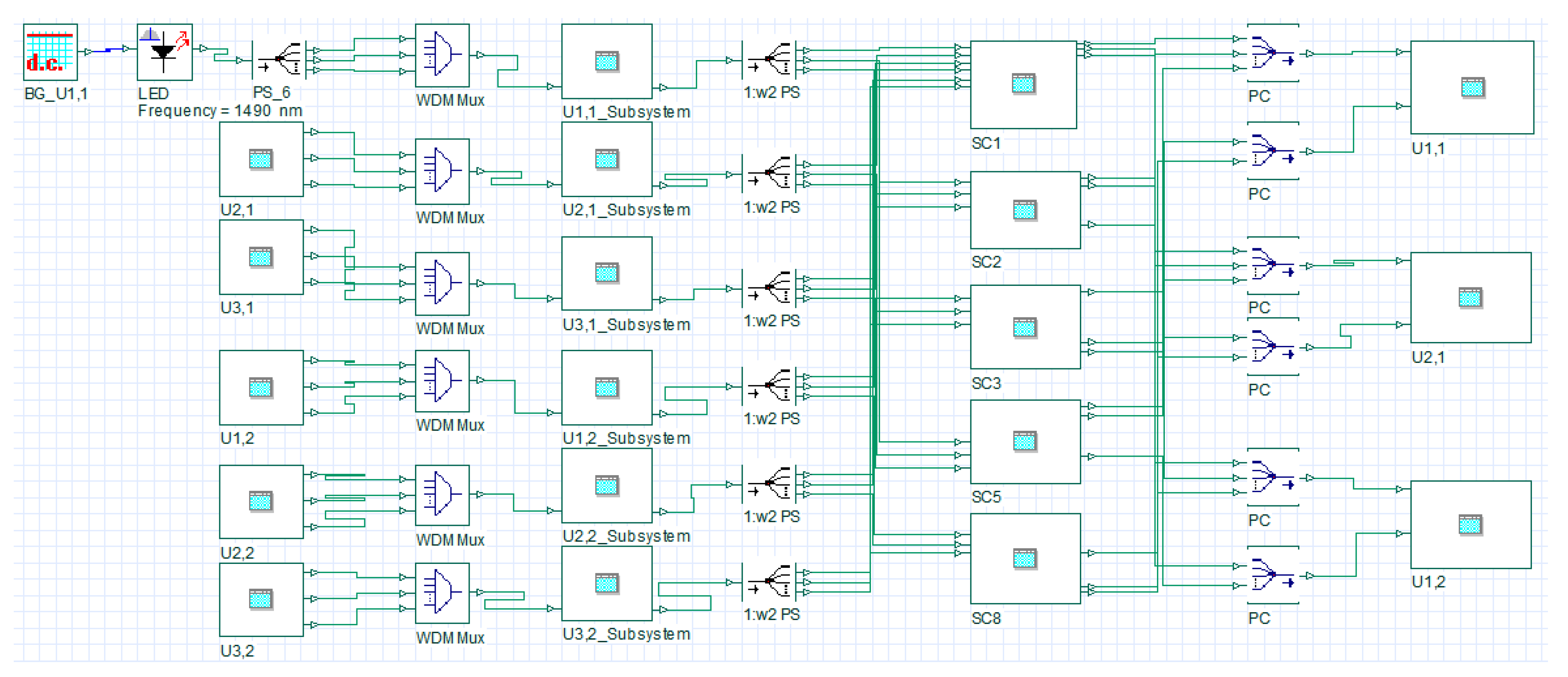
3.1. Structure of 2D-BIBD System

The transmitter and receiver modules ( N 1 × N 2 ) of the 2D-BIBD system encompasse several encoder and decoder arrangements. For a single user, each transmitter modules is formed by the combination of a light-emitting diode (LED), a Mach–Zehnder Modulator (MZM) and uniform fiber Bragg gratings (FBGs) filters. A LED, with a broad optical spectrum, is used to provide the required optical spectrum for the encoding operation. The spectrum from the LED is modulated with the help of a MZM as per the binary data generated by the pseudo-random bit sequence (PRBS) source, also referred to as an ON-OFF keying scheme. The MZM modulator converts the electrical signals into optical pulses and delivers them to the FBGs based encoder [14,22].
Before discussing the structures for the transmitter and receiver modules in detail, it is important to discuss the encoder and decoder design to facilitate the understanding of the proposed 2D-BIBD OCMDA based architecture. The encoder arrangement converts the binary 1s into spectral and spatial representations for every user based on the Xth and Yth code sequences of the 2D-BIBD code. The encoder module contains two functions: (i) spectral encoding and (ii) spatial encoding. The arrangement of the FBG filters, as shown in Figure 1, is used to perform the spatial encoding of impulses as per the X h part of the coding scheme. A tree coupler with optical splitters is used to perform the decoding operation. Split parts of the spectrally encoded spectrum are forwarded to the respective star coupler input ports.
The decoder function is used to recuperate the required encoded spectrum with determined auto- and cross-correlation values. The decoder arrangement includes two operations: (i) spatial decoding and (ii) spectral decoding. The spatial decoder is made up of couplers and optical splitters in reverse order to that of the spatial encoder. Each port of the coupler corresponds to the respective spectral decoder, optical combiners, and two balanced detectors (BD1 and BD2).
The receiver module is designed using a double-balanced detection technique, and it produces successive codewords using the required spectrum. This technique also suppresses MAI, generated from different spectral code sequences due to the balanced photodiode configuration [14,23]. The system consists of multiple transmitter and receiver sections ( N 1 × N 2 ), and each pair uses the C g , h 2D-BIBD code sequence.

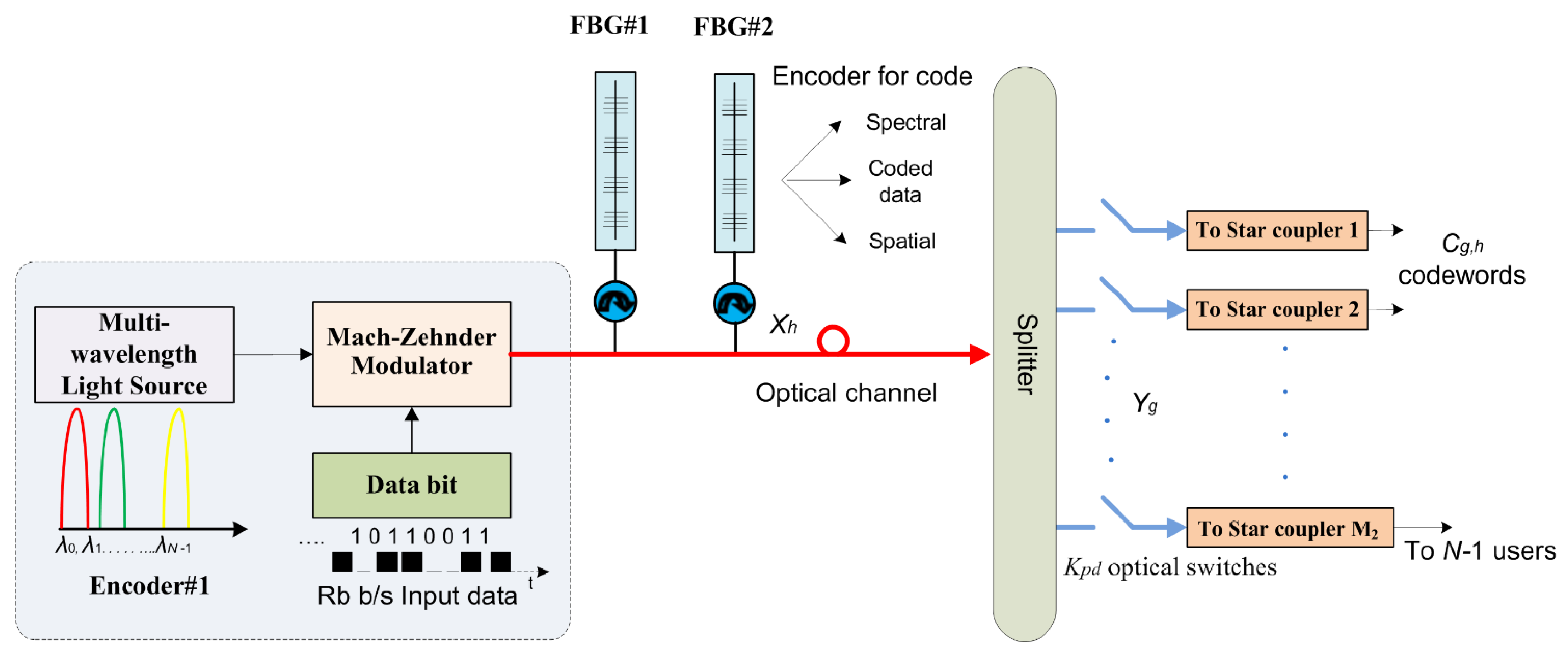
3.2. Construction of 2D-BIBD Transmitter Architecture

The transmitter module employs a combination of FBG filters and optical splitters with k p d optical switches to perform the required spectral-spatial encoding operation. For a single user, a LED is used to generate the required spectrum for encoding and transmission of binary data over the optical medium. The end-face of the LED is connected to a MZM, which uses on-off keying (OOK) to modulate the user’s binary data sequence with the LED spectrum (Figure 1). The output of the MZM is fed to a special arrangement of FBG filters that encodes the modulated spectrum in the spectral domain. Figure 1 shows a combination of two filters, FBG#1 and FBG#2, an optical splitter, and M 2 star couplers for user 1, to allow the spectrum in accordance with the X 1 coding scheme of the proposed code.
In the process of spectral encoding, optical pulses are initially delivered to FBG#1, which is used to reflect the spectral components according to the position of 1s in the X 1 coding scheme. The rest of the spectrum is filtered out by FBG#1. The round trip delays of the matched spectral components are different as the matched spectral components are reflected by different gratings. To compensate for the delay, FBG#2 is used.
This process introduces the X h spectral encoding to the 1D-BIBD code. FBG#1 and FBG#2 have the same grating characteristics. However, the FBG#1 grating structure is made in the reverse order to that of the FBG#2 to avoid time spreading.
The FBG#2 reflected pulses are sent to an optical splitter that is used to perform a Y g T spatial encoding operation and produces the intended C g , h 2D-BIBD code sets. In spatial encoding, the optical splitter equally divides each matched spectral component power into w 2 portions due to the w 2 code weight of the spatial code pattern. Finally, according to the spatial code pattern Y g , these w 2 split portions of the encoded spectrum are further sent to M2 star couplers, which correspond to the 1s of the spatial code pattern, through k p d optical switches.

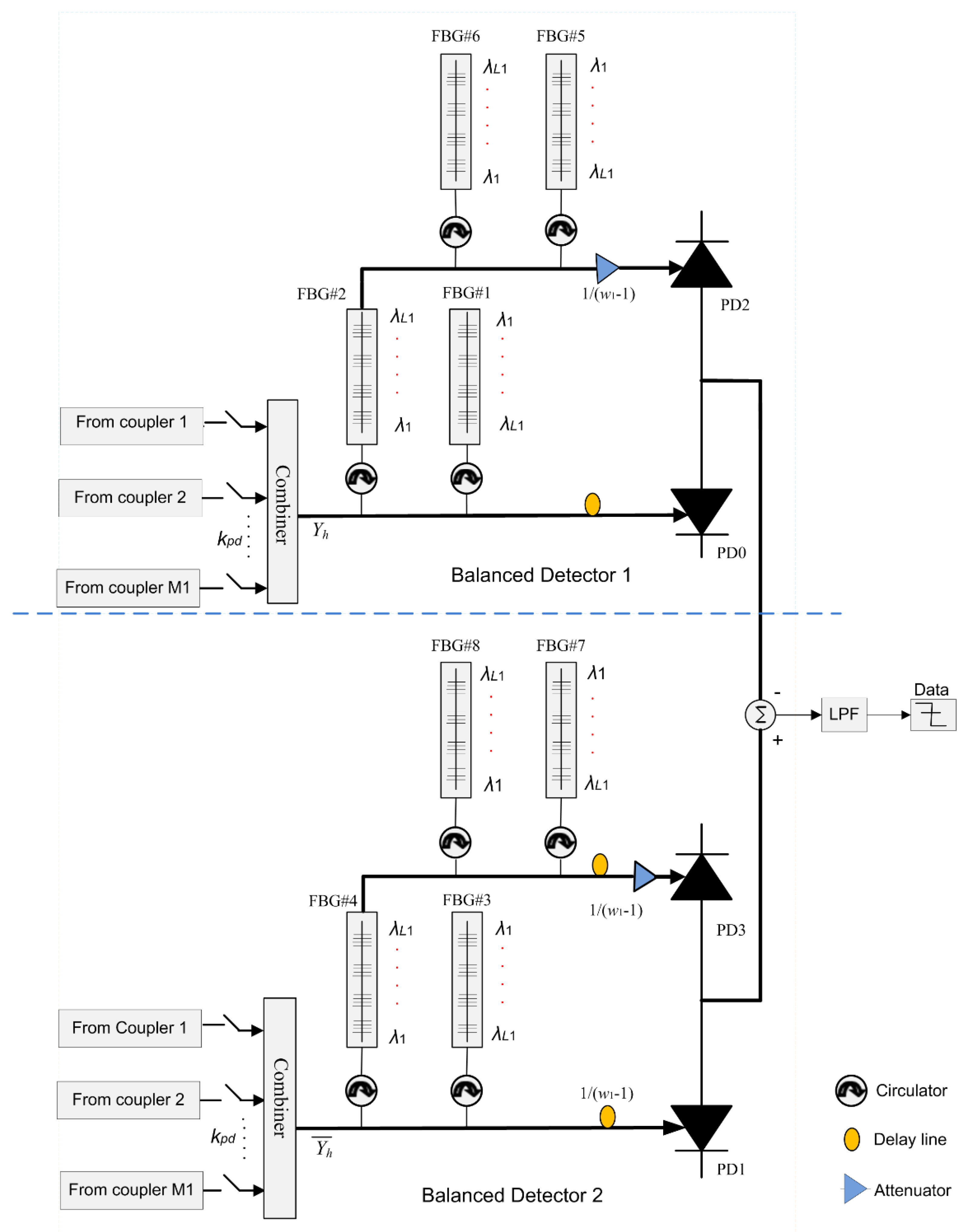
3.3. Construction of 2D-BIBD Receiver Architecture

The receiver module of 2D-BIBD OCDMA system consists of multiple star couplers, optical combiners, two balanced detectors followed by a low-pass Bessel filter section, an optical adder, and an integrator to implement the desired decision (Figure 2). Further, each balanced detector section is composed of two photodiodes (PD0-PD2 and PD1-PD3) connected in a balanced mode. Spatial decoding is performed by the combination of k p d optical switches and two optical power combiners. FBG filters are used for the spectral decoding operation. Additonnally, the optical combiner combines the optical signals obtained by the star couplers i.e., it connects consistent star couplers with a balanced detector. The selection of the star coupler depends on the location of binary 1s in the Yth code sequence.
Upper and lower optical combiners receive and combine the signals from the multiple star couplers. The optical combiner at the upper side combines the star couplers’ signals, which are matched to the spatial code pattern Y g T (1s of the spatial code pattern). Whereas, the lower optical combiner is used to receive and mix the signals from the consistent star couplers, which are further matched to the complementary spatial code pattern Y T ¯ g (1s of the spatial code pattern).
There are four sets of FBGs, two attenuators, two PIN diodes, and four circulators. FBG#1 and FBG#8 have equal number of gratings. FBG#2 and FBG#4 which are structured according to the spectral code pattern X h , are used to extract the spectral components, which are matched with the 1s of the X h .
FBG#1 and FBG#3 have the same number of gratings as FBG#2 and FBG#4. The configurations of FBG#2 and FBG#4 are set totally reverse to that of FBG#1 and FBG#3 to compensate for the round-trip delay. In the same way, FBG#6 and FBG#8 are constructed consistent with the complementary spectral code sequence X ¯ h . Their combination is used to extract the spectral components, which correspond to the “1s” of the additional spectral code sequence X ¯ h . (FBG#5 and FBG#7) and (FBG#6 and FBG#8) have the same gratings, except that the arrangements are totally reverse to compensate for the round-trip delays of signals [9,16].
Both balanced detectors operations are similar except for the attenuation values. In this case, the spectral components which are matched with FBG#2 are transmitted to FBG#1 and a delay line. The function of the delay line is to compensate for the delay caused by FBG#5 and FBG#6. After this, optical pulses are sent to photo diode PD0. In the same way, the spectral components matched with FBG#6 are further sent to FBG#5 and an optical attenuator (value set to [ 1 / ( w 1 1 ) ] ) which is derived from the SNR expression analysis of the proposed 2D-BIBD code. Next, optical pulses are sent to PD2.
In the BD2 operation, the spectral components matched to FBG#4 are sent to FBG#3, through an attenuator and a delay line, which compensates for the delay caused by FBG#8 and FBG#7. In this case, the attenuator value is set to [ 1 / ( w 1 1 ) ] . The optical pulses are sent to PD1. Similarly, spectral components which are matched to FBG#8 are further sent to FBG#7 and an optical attenuator (value set to [ 1 / ( w 1 1 ) ] ).
During the whole process, only those signal components which are matched to the spatial and spectral code patterns of the receiver reach PD0. Spectrally decoded data has been converted into electrical output using PD0 and PD2. These two output currents are combined and passed to the integrator and the low pass filtering operation. The difference in outputs of PD0 and PD2 and PD1 and PD3 are R ( 0 ) ( g , h ) and R ( 2 ) ( g , h ) / ( w 1 1 ) , respectively, and provide complete elimination of multiuser interference (Equation (9)).

4. 2D-BIBD System Performance Analysis

The Gaussian approximation is applied to evaluate the 2D-BIBD code performance of the SAC based OCDMA system. PIIN shot noise and thermal noise were considered in our analysis. We performed the study by referring to BER and with the help of varying different performance parameters such as received power, the number of users, etc. To measure the required signal to noise ratio (SNR), the photocurrent noise can be represented as:
i n o i s e 2 =   i P I I N 2 +   i s h o t 2 +   i t h e r m a l 2  
where, i s h o t 2 , i P I I N 2 , and i t h e r m a l 2 represent shot noise, phase induced intensity, and thermal noise originated at the receiving end, respectively. Therefore, Equation (10) can be rewritten as:
i noise 2 = I r e c 2 B r e c τ r e c + 2 e I T o t a l B r e c + 4 K b T n B R N  
where, I r e c and I T o t a l represent the average of total photocurrents, respectively. τ r e c and B r e c represent the coherence time of incident light on the photodiode and the receiver electrical bandwidth, respectively. Further K b , R N , T n , and e represent Boltzmann’s constant, the load resistance, the absolute temperature, and the electron’s charge, respectively. Here, τ r e c can be written as
τ r e c = 0 G 2   ( v ) d v [ 0 G   ( v ) d v ] 2
where r ( v ) denotes the single sideband source power spectral density (PSD) for the receiving end’s optical signals. Thus, PSD can be represented as:
r ( ν ) = P s r w 2 Δ ν k = 0 K 1 d ( k ) i = 0 L 2 1 j = 0 L 1 1 c I , j ( k ) u ( ν , i ) d ν
where P s r   represents the effective transmitter power at the photodiode. w 1 and w 2 are the code weights of the 2D-BIBD code, and K is the number of simultaneous users. The user data bit is denoted by d ( k ) . L 1 and L 2 , respectively, represent lengths of the spatial and spectral codes. C i , j ( k ) denotes the k t h user element code word.
ϕ ( ν , i ) is defined as follows:
ϕ ( ν , i ) = { u [ ν ν 0 Δ ν 2 L 1 ( L 1 + 2 i 2 ) ] u [ ν ν 0 Δ ν 2 L 1 ( L 1 + 2 i ) ] }  
where u ( v ) shows the unit step function and is expressed as:
u ( v ) = { 1 ,             v 0 0 ,             v < 0
Optical signals PSDs at PDs 0-1 at the receiving end can be obtained using the cross-correlation between C ( d ) and C g , h . This can be expressed as:
G 0 ( ν ) = P s r w 2 Δ ν k = 0 K 1 d ( k ) i = 0 L 2 1 j = 0 L 1 1 c i , j ( 0 ) c I , j ( k ) u ( ν , i )  
G 1 ( ν ) = P s r ( w 1 1 ) w 2 Δ ν k = 0 K 1 d ( k ) i = 0 L 2 1 j = 0 L 1 1 c i , j ( 2 ) c I , j ( k ) u ( ν , i )  
For worst-case analysis, the first step is to set d ( k ) = 1 and output currents ( I P D 0 I P D 1 ) obtained using   G 0 ( ν ) and G 1 ( ν ) . This can be expressed as follows.
First photodiode (PD0):
I P D 0 = R 0 G 0 ( ν ) d ν = R P s r w 2 Δ ν 0 k = 0 K 1 d ( k ) i = 0 L 2 1 j = 0 L 1 1 c i , j ( 0 ) c I , j ( k ) u ( ν , i ) = R P s r w 2 L 1 [ w 2 w 1 + w 2 ( K 1 ) ( L 2 1 ) L 2 L 1 1 ]  
Second photodiode (PD1):
I P D 1 = R 0 G 1 ( ν ) d ν = R P s r w 2 ( w 1 1 ) Δ ν 0 k = 0 K d ( k ) i = 0 L 2 1 j = 0 L 1 1 c i , j ( 2 ) c I , j ( k ) u ( ν , i )   = R P s r w 2 ( w 1 1 ) L 1 [ w 2 ( w 1 1 ) ( K 1 ) ( L 2 1 ) L 2 L 1 1 ] = R P s r w 2 L 1 [ w 2 ( K 1 ) ( L 2 1 ) L 2 L 1 1 ]  
where, R represents the photodiode responsivity, which is the gain of the input-output detector
R = λ e h V c    
Here, λ ,   e , V c , and h represent the quantum efficiency, electron charge, central frequency of the original broadband optical pulse, and Planck’s constant, respectively.
The expression for the average received photocurrents ( I r e c ) is calculated as follows.
  • I rec = R 0 [ G 0 ( ν ) G 1 ( ν ) ] d ν   I rec = I P D 0 I P D 1 I rec = R P s r w 1 L 1
PIIN current variance is expressed as
i P I N 2 =   I 2 B r e c τ r e c
i P I I N 2 = B r e c I r e c 2 0 [ G 0 G 1 ] 2 d v [ 0 ( G 0 G 1 ) d v ] 2
Hence
i P I I N 2 = B r e c R 2 0 [ G 0 2 + G 1 2 2 G 0 G 1 ] d ν  
i P I I N 2 = B r e c R 2 0 [ ( G 0 G 1 ) 2 ] d ν  
Incident power on photodiodes ( G 0 2 ( v ) ,   G 1 2 ( v ) ) was derived from Equations (18) and (19). This can be written as:
0 G 0 2 ( ν ) d ν = P s r 2 w 2 2 Δ ν 2 0 [ k = 0 K 1 d ( k ) i = 0 L 2 1 j = 0 L 1 1 c i , j ( 0 ) c I , j ( k ) u ( ν , i ) ] 2 d ν   =   P s r 2 w 2 2 Δ ν 2 Δ ν L 1 [ k = 0 K 1 d ( k ) i = 0 L 2 1 j = 0 L 1 1 c i , j ( 0 ) c i , j ( k ) u ( ν ) ] 2 = P s r 2 w 2 2 L 1 w 1 Δ ν   [ w 1 w 2 + w 2 ( K 1 ) ( L 2 1 ) L 1 L 2 1 ] 2 =   L 1 I P D 0 2 R 2 w 1 Δ ν
0 G 1 2 ( ν ) d ν = P s r 2 ( w 1 1 ) 2 w 2 2 Δ ν 2 0 [ k = 0 K 1 d ( k ) i = 0 L 2 1 j = 0 L 1 1 c i , j ( 2 ) c I , j ( k ) u ( ν , i )   ] 2 d ν = P s r 2 ( w 1 1 ) 2 w 2 2 w 1 Δ ν 2 Δ ν L 1 [ k = 0 K 1 d ( k ) i = 0 L 2 1 j = 0 L 1 1 c i , j ( 2 ) c i , j ( k ) u ( ν , i ) ] 2 = P s r 2 w 1 ( w 1 1 ) 2 w 2 2 L 1 Δ ν [ w 2 ( w 1 1 ) ( K 1 ) ( L 2 1 ) L 1 L 2 1 ] 2 = L 1 I P D 1 2 w 1 R 2 Δ ν
The following section explains the single-sideband PSD from source multiplications. For PD0 and PD1 of the receiver.
0 G 0 ( ν ) G 1 ( ν ) d ν = P s r 2 w 2 2 ( w 1 1 ) Δ ν 2 0 [ k = 0 K 1 d ( k ) i = 0 L 2 1 j = 0 L 1 1 c i , j ( 0 ) c i , j ( k ) u ( ν ) ] [ k = 0 K 1 d ( k ) i = 0 L 2 1 j = 0 L 1 1 c i , j ( 2 ) c ( k ) u ( ν ) ] d ν = P s r 2 w 2 2 ( w 1 1 ) Δ ν 2 Δ ν L 1 i = 0 L 2 1 [ k = 0 K 1 j = 0 L 1 1 c i , j ( 0 ) c i , j ( k ) u ( ν ) ] [ k = 0 K 1 j = 0 L 1 1 c i , j ( 1 ) c i , j ( k ) u ( ν ) ] = P s r 2 w 2 2 ( w 1 1 ) w 1 L 1 Δ ν [ w 1 w 2 + w 2 ( K 1 ) ( L 2 1 ) L 1 L 2 1 ] [ w 2 ( w 1 1 ) ( K 1 ) ( L 2 1 ) L 1 L 2 1 ] =   L 1 I P D 0 I P D 1 R 2   w 1 Δ ν  
We obtain the variance of the PIIN current after substituting Equations (24)–(26) in the Equation (22) ,   which is as follows:
i P I I N 2 = B r e c R 2 [ L 1 I P D 0 2 w 1 R 2 Δ ν + L 1 I P D 1 2 w 1 R 2 Δ ν 2 L 1 I P D 0 I P D 1 w 1 R 2 Δ ν ] = B r e c L 1   w 1 Δ ν ( I P D 0 I P D 1 ) 2
For every user, “1” and “0” are transmitted with the same probability. Thus, Equation (27) can be rewritten as follows:
i P I I N 2 = B r e c L 1   2 w 1 Δ ν ( I P D 0 I P D 1 ) 2    
The shot noise current variance is expressed as:
i s h o t 2 = 2 e B I t o t a l = 2 e B [ I P D 0 + I P D 1 ]
The thermal noise is given as:
i t h e r m a l 2 = 4 K b T n B R N  
Therefore, the S N R = I rec 2 i n o i s e 2 of the 2D-BIBD based OCDMA system can be expressed as:
S N R = [ R P s r w 1 L 1 ] 2 B r e c L 1   2 w 1 Δ ν ( I P D 0 I P D 1 ) 2 + e B [ I P D 0 + I P D 1 ] + 4 K b T n B R N  
The Gaussian approximation was used to derive the BER from the SNR using the following equation:
B E R =   1 2 erfc ( S N R 8 )
where, erfc ( x ) =   2 π exp ( z 2 ) d z .

5. Results and Analysis

5.1. Numerical Analysis

The parameters used for theoretical and simulation analysis of the 2D-BIBD code based OCDMA system are listed in Table 4. The effective source power ( P s r ) was set to −10 dBm, and simulations were carried out at a bit rate of 622 Mbps. The SNR is a relevant term as it demonstrates the received signal quality. BER performance improves with the increase in SNR. Therefore, 2D-BIBD code performance uses multiple parameters, such as the number of supportable users and received output power for various types of noises.
Figure 3 shows the BER performance for the proposed code concerning the number of supportable users. As the number of users increases, the quality of the received signal decreases due to MAI. Thus, SNR and BER degrade. Moreover, BER values of the 2D-BIBD ( N m a x = 63 , N m a x = 3 ) code were compared with existing techniques such as DPD ( M = 63 , P = 3 ) and DEU ( M = 63 , P = 3 ) codes. It was observed that supported users were 90, 70, and 25 for 2D-BIBD, 2D-DPD, and 2D-DEU codes, respectively, at the minimum allowed BER value of 10 9 . Further, a large code cardinality is achieved due to the improved cross-correlation properties (Table 3) of the proposed code. Figure 4 represents the relationship between BER and P s r at a bit rate of 622 Mb/s. We selected 20 active users for performance comparison, and the BER changed due to variations in the received power. However, it was observed that the BER’s performance could not be enhanced with an increase of the transmitted power.
The 2D-BIBD ( N m a x = 63 , N m a x = 3 ) code outperformed the 2D-DPD (M = 63, P = 3) and 2D-DEU (M = 63, P = 3) codes. This system achieved the desired optical transmission performance at the smallest effective transmitted 2D-BIBD power ( P s r   = −27.5 dBm) when compared to 2D-DEU (−26.8 dBm) and 2D-DPD (−25.8 dBm) codes, respectively. The main factor in 2D code design is spatial code length. Due to its optimal spatial code length, the system with 2D-BIBD code requires a smaller effective transmitted power. Additionally, interference from other users is decreased by increasing the number of star couplers and filters required for spatial encoding purposes.
PIIN is introduced in the system with the mixing of the incoherent light fields, and it further affects the photodiode detector, which leads to high-intensity noise. Further, higher weight in the 2D code adds more intensity noise in the system. The relation between BER and P s r for different noise combinations such as PIIN-shot-thermal for 2D-BIBD and PIIN-Shot for 2D-DEU and 2D-DPD is shown in Figure 5. We selected 20 active users and a 622 Mbps data rate for performance comparison. The BER varied due to variations in the received power. In addition, the 2D-BIBD code provides the desired optical transmission requirements with minimum transmitted adequate power ( P s r = −27.5 dBm). Therefore, improvement in BER was obtained when compared to other codes such as DEU ( P s r = −26.5 dBm) and DPD ( P s r = −25.5 dBm). It is also observed that PIIN was the dominating noise in the system and occurred due to a change in the amount of received power. Further, PIIN is directly proportional to the number of interfering users, and therefore the power received is inversely proportional to the quantity of interfering users. However, interference noise is reduced due to the excellent cross-correlation properties of the proposed code and resulted in the suppression of intensity noise (Figure 5).
Figure 6 shows the variations between BER and broadband source (BBS) effective width for 20 active number of users, a data rate at 622 Mbps and P s r at −10 dBm. It is observed that the spectral width is inversely proportional to the BER for all the systems. The BER performance of the 2D-BIBD code is improved due to its low in-phase cross-correlation properties when compared to the 2D-DPD and 2D-DEU codes. Moreover, the BER performance could be improved by enhancing the spatial code length. The 2D-BIBD code outperforms the 2D-DPD and 2D-DEU codes at a spectral width of 7 THz for error-free transmission.

5.2. Simulation Analysis

The proposed coding scheme and corresponding system architecture performance was verified by implementation in a highly acknowledged software called Optisystem. The simulation model was developed according to the structure of the transmitter and receiver modules in Figure 1 and Figure 2, respectively. For the simulation setup, the transmitter module contains a broadband source (BBS) with a 30 nm spectral width. For a single user, the end-face of the BBS is fed into a 1:3 power splitter used to split the spectrum into three equal portions for the spectral encoding operation. The spectral encoder is employed using a multiplexer arrangement (MUX) with three input ports and a single output port. Each port is used to carry the signal toward a specially configured bandpass filter to allow the spectrum according to the chip placement of the spectral coding sequence (Figure 7). The spectrally encoded spectrum is then fed into the Mach Zehnder Modulator (MZM), which is further connected to the spatial encoding arrangement. For a single user, the spatial encoder is employed using a power splitter arrangement with 1:w2 ports. Each port is used to split the spectrally encoded spectrum in equal proportions and forward it towards a specific star coupler. The connection between the output legs of the power splitter and star coupler is defined by the placement of 1s in the spatial code sequence. Outputs of the star coupler are further divided into two parts where the upper side is used to provide the encoded spectrum to balanced detector 1 of the desired user and the bottom side is configured to provide the encoded received signal to balanced detector 2 of the user compliment to the desired one.
As proof of concept simulation analysis was performed for a total of six users. Code sequences from Table 2 were used to design the simulation model. Wavelengths and star couplers allocation for a single user (User 1) was selected as shown in Table 5. EDFAs were employed in the simulation model to compensate for the power drops across the network. Finally, the analysis was performed for a back-to-back model by connecting the transmitter and receiver module directly.
The balanced detector is essentially made from the combination of uniform FBG filters with a bandwidth of 0.4 nm to recover the signal with maximum auto and zero cross-correlation at the receiving end.
Figure 8 shows the eye diagram for the proposed setup when six users communicate simultaneously at 1, 1.5, 2, and 2.5 Gbps. It is evident from the eye openings that the proposed model can provide the required performance and support multiple users communicating at significant data rates.
Figure 9 shows the variation of BER and Q factor as a function of data rate for six users at −10 dBm received power. The Q-factor performance provides a qualitative description of the optical receiver performance; the performance of an optical receiver depends on the signal-to-noise ratio (SNR). The Q-factor suggests the minimum SNR required to obtain a specific BER for a given signal. Obtained Q and BER values at different data rates are as follows: 1 Gbps (Max. Q = 8.4, Min. BER = 4.6 × 10¹⁴), 1.5 Gbps (7.4, 3.9 × 10¹¹), 2 Gbps (7.01, 6.59 × 10¹⁰), and at 2.5 Gbps (6.42, 8.36 × 10⁹), respectively. It is clear from the results that the SAC based OCDMA system with the proposed code provides low error performance for data rates up to 2.5 Gbits/s. The increase of the data rate has a negative impact on both the BER and Q factor in which chips spacing became minimal, thus, increasing inter-symbol interference (ISI), eventually leading to performance deterioration.

6. Conclusions

In this study, a new 2D code extended from 1D-BIBD codes was proposed, and its performance was analyzed using theoretical, numerical analysis, and simulations. We designed the SAC based OCDMA system architecture with the help of the proposed 2D-BIBD code. Results of the proposed 2D-BIBD code were compared with existing 2D spectral/spatial codes such as DEU and DPD. 2D-BIBD surpassed the 2D-DEU and 2D-DPD code’s performances, which indicated that there was a cardinality enhancement of 72% and 22%, respectively, for the proposed code when compared to 2D-DEU (25 versus 90 active users) and 2D-DPD (70 versus 90 active users) and for the same transmission conditions. Performance analysis of the proposed 2D-BIBD code showed a reduction in MAI and its associated PIIN effects. These effects were generated by the overlapping of chip spectra among signature code sequences, and their effects can be compensated by the low cross-correlation properties of the 2D-BIBD code. This resulted in improved system performance in terms of the maximum code cardinality and BER. Results showed that the 2D-BIBD based system provides high spectral density and offers solutions for the limited bandwidth of light sources. It was also observed that the system capacity and data transmission rates were increased with the increase in the spatial length. Results show that our proposed code provided practical code length with minimum cross-correlation and resulted in the minimum probability of error and MAI. Our results were validated with simulation analysis and agreed with the performance of the proposed code for low-error transmission.
The numerical analysis concluded that the proposed code provided better BER and SNR performance when compared to other 2D codes, for instance, 2D-DPD and 2D-DEU. In addition, the proposed code provided optical transmission performance with minimum P s r = −27.5 dBm when compared to existing 2D-DEU and 2D-DPD codes. Overall, simulation results matched closely with the theoretical analysis. This study suggests that the proposed technique would be useful to increase the spectral width of broadband sources and reduce the need for effective source power with enhancement in spatial code length.

Author Contributions

T.S., H.Y.A., A.C. and W.A.I. designed the research. T.S., H.Y.A., A.C. and M.Z. performed the code programming. W.A.I. carried out simulation analysis. T.S., H.Y.A. and A.C. performed the analysis of the results and the results interpretation. T.S., H.Y.A. and M.Z. wrote the first draft together, supported by A.C., T.S. and A.C. and P.F. commented on the draft and all authors finalized it. T.S. is the corresponding author. All authors have read and agreed to the published version of the manuscript.

Funding

This work was partially funded by the support program for research and creation development (PSDrc) of the University of Québec in Chicoutimi.

Institutional Review Board Statement

Not applicable.

Informed Consent Statement

Not applicable.

Data Availability Statement

Not applicable.

Conflicts of Interest

The authors declare no conflict of interest.

References

  1. Kwong, W.C.; Perrier, P.A.; Prucnal, R. Performance comparison of asynchronous and synchronous code-division multiple-access techniques for fiber-optic local area networks. IEEE Trans. Commun. 1991, 39, 1625–1634. [Google Scholar] [CrossRef]
  2. Salehi, J.A. Emerging OCDMA communication systems and data networks. J. Opt. Netw. 2007, 6, 1138–1178. [Google Scholar] [CrossRef] [Green Version]
  3. Ghafouri-Shiraz, H. Optical CDMA Networks: Principles, Analysis and Applications; Wiley: New York, NY, USA, 2012. [Google Scholar]
  4. Inaty, E.; Shalaby, H.M.H.; Fortier, P. On the cutoff rates of a multiclass OFFH-CDMA system. IEEE Trans. Commun. 2005, 53, 323–334. [Google Scholar] [CrossRef]
  5. Sharma, T.; Maddila, R.K. Optical Code Construction Based on Enhanced Quantum Logic Gate (EQLG) Technique for Spectral Amplitude Coding Optical CDMA Systems. Wirel. Pers. Commun. 2020, 113, 2587–2609. [Google Scholar] [CrossRef]
  6. Yang, C.-C. The application of spectral-amplitude-coding optical CDMA in passive optical networks. Opt. Fiber Technol. 2008, 14, 134–142. [Google Scholar] [CrossRef]
  7. Sharma, T.; Maddila, R.K.; Aljunid, S.A. Simulative investigation of spectral amplitude coding based OCDMA system using quantum logic gate code with NAND and direct detection techniques. Curr. Opt. Photonics 2019, 3, 531–540. [Google Scholar]
  8. Huang, J.F.; Chang, Y.T. Incoherent hybrid spectral polarization and amplitude coding implemented with specified orthogonal ternary code over balanced photo-detectors. In Proceedings of the 4th Annual Communications Networks and Services Research Conference, Moncton, NB, Canada, 24–25 May 2006; p. 8. [Google Scholar]
  9. Lin, C.-H.; Wu, J.-S.; Yang, C.-L. Noncoherent spatial/spectral optical CDMA system with two-dimensional perfect difference codes. J. Lightwave Technol. 2005, 23, 3966–3980. [Google Scholar]
  10. Ahmed, H.Y.; Zeghid, M.; Imtiaz, W.H.; Sharma, T.; Chehri, A.; Fortier, P. Two-Dimensional Permutation Vectors’ (PV) Code for Optical Code Division Multiple Access Systems. Entropy 2020, 22, 576. [Google Scholar] [CrossRef]
  11. Sharma, T.; Maddila, R.K. Performance characteristics of the spectral amplitude-coding optical CDMA system based on one-dimensional optical codes and a multi-array laser. Ukr. J. Phys. Opt. 2019, 20, 81–90. [Google Scholar]
  12. Abdulqader, S.G.; Aljunid, S.A.; Khafaji, A.; Fadhil, H.M. Enhanced performance of SAC-OCDMA system based on SPD detection utilizing EDFA for access networks. J. Commun. 2014, 9, 99–106. [Google Scholar] [CrossRef]
  13. Sun, S.; Ying, H. A new family of 2D optical orthogonal codes and analysis of its performance in optical CDMA access networks. IEEE J. Lightwave Technol. 2006, 4, 1646–1653. [Google Scholar]
  14. Shivaleela, S.; Srinivas, T. Construction of wavelength/time codes for fiber-optic CDMA networks. IEEE J. Lightwave Technol. 2007, 3, 1370–1377. [Google Scholar] [CrossRef] [Green Version]
  15. Nisar, K.S. Numerical construction of generalized matrix partitioning code for spectral amplitude coding optical CDMA systems. Optik 2017, 130, 619–632. [Google Scholar] [CrossRef]
  16. Ahmed, H.Y.; Zeghid, M.; Imtiaz, W.A.; Sghaier, A. Two-dimensional Fixed Right Shift (FRS) code for SAC-OCDMA systems. Opt. Fiber Technol. 2019, 47, 73–87. [Google Scholar] [CrossRef]
  17. Chang, Y.T.; Huang, J.F.; Yen, C.T.; Wang, C.C.; Cheng, H.C.; Hsu, K.C. A new shared AWG-based OCDMA scheme implemented with time-spreading and wavelength-group-hopping embedded M-sequence code. Opt. Fiber Technol. 2010, 16, 114–123. [Google Scholar] [CrossRef]
  18. Kandouci, C.; Djebbari, A. Design of new hybrid wavelength hopping/time spreading codes for optical CDMA by combining OCC and BIBD ZCC codes. Optik 2017, 133, 73–79. [Google Scholar] [CrossRef]
  19. Aishah, H.; Anuar, M.S.; Aljunid, S.A.; Arief, A.R. Performance evaluation of 2D hybrid code vs 2D M-matrices code in SAC-OCDMA systems. In Proceedings of the 2013 IEEE 4th International Conference on Photonics (ICP), Melaka, Malaysia, 28–30 October 2013; pp. 224–226. [Google Scholar]
  20. Ravi, M.K.; Pathak, S.S.; Chakrabarti, N.B. A New Multi Wavelength—Optical Code Division Multiple Access Code Design Based on Balanced Incomplete Block Design. In Proceedings of the Nternational Conference on Industrial and Information Systems, Peradeniya, Sri Lanka, 8–11 August 2007; pp. 163–168. [Google Scholar]
  21. Djebbari, A.; Garadi, A.; Dayoub, I.; Ahmed, A.T. A new code construction with zero cross-correlation based on BIBD. Optik 2013, 124, 3419–3421. [Google Scholar] [CrossRef]
  22. Yang, C.C.; Huang, J.F. Two-dimensional M-matrices coding in spatial/frequency optical CDMA networks. IEEE Photonics Technol. Lett. 2003, 15, 168–170. [Google Scholar] [CrossRef]
  23. Kadhim, R.A.; Fadhil, H.A.; Aljunid, S.A.; Razalli, M.S. A new two dimensional spectral/spatial multi-diagonal code for noncoherent optical code division multiple access (OCDMA) Systems. Opt. Commun. 2014, 329, 28–33. [Google Scholar] [CrossRef]
  24. Abdullah, A.R.; Aljunid, S.A.; Safar, A.M.; Nordin, J.M.; Ahmad, R.B. Mitigation of multiple access interference using two-dimensional modified double weight codes for optical code division multiple access systems. Opt. Eng. 2012, 51, 065007. [Google Scholar] [CrossRef]
  25. Yeh, B.C.; Lin, C.H.; Yang, C.L.; Wu, J. Noncoherent spectral/spatial optical CDMA system using 2D diluted perfect difference codes. J. Lightwave Technol. 2009, 27, 2420–2432. [Google Scholar]
  26. Najjar, M.; Jellali, N.; Ferchichi, M.; Rezig, H. Spectral/spatial optical CDMA code based on diagonal eigenvalue unity. Opt. Fiber Technol. 2017, 38, 61–69. [Google Scholar] [CrossRef]
Figure 1. Transmitter structure of the 2D balanced incomplete block design (BIBD) OCDMA system.
Applsci 11 00783 g001
Figure 2. Receiver structure of the 2D-BIBD OCDMA system.
Applsci 11 00783 g002
Figure 3. Dependence of BER on the maximum number of simultaneous users (K) at input transmitted power (Psr = −10 dBm) for 2D-BIBD (Nmax = 63, N’max = 3), 2D-DEU code (M = 63, P = 3), and 2D-DPD (M = 63, P =3).
Applsci 11 00783 g003
Figure 4. 2D-BIBD code’s performance in terms of BER and effective source power (Psr) at a data rate of 622 Mbps and the number of users K = 20.
Applsci 11 00783 g004
Figure 5. Relationship between BER and effective source power for specific 20 users at a data rate of 622 Mbps.
Applsci 11 00783 g005
Figure 6. Relationship between BER and broadband source spectral width with 20 active users and a data rate of 622Mbps.
Applsci 11 00783 g006
Figure 7. Simulation model of 2D-BIBD code for six users at 1 Gbps and −10 dBm input power.
Applsci 11 00783 g007
Figure 8. Eye diagram indicating performance of six users with different data rates: (a) 1 Gbps: Max. Q = 8.4, Min. BER = 4.6 × 10⁻¹⁴ (b) 1.5 Gbps: Max. Q = 7.4, Min. BER = 3.9 × 10⁻¹¹ (c) 2 Gbps: Max. Q = 7.01, Min. BER = 6.59 × 10⁻¹⁰ (d) 2.5 Gbps: Max. Q = 6.42, Min. BER = 8.36 × 10⁻⁹.
Applsci 11 00783 g008
Figure 9. Data rate versus: (a) Q factor, (b) BER for six users at −10 dBm received power.
Applsci 11 00783 g009
Table 1. An example of 1D balanced incomplete block design (BIBD) code sets X ( N m a x   =   3 ; w 1   =   3 ) and Y ( N m a x   = 2   ; w 2   =   3 ).
N m a x   =   3 ,   w 1   =   3 N m a x = 2 ,   w 2   =   3
Code Position X h   =   Code   Set Code Position Y g   =   Code   Set
λPOS1={2,3,14}[0 1 1 0 0 0 0 0 0 0 0 0 0 1 0 0 0 0 0]λPOS1={2,5,6}[0100110000000]
λPOS2={3,4,15}[0 0 1 1 0 0 0 0 0 0 0 0 0 0 1 0 0 0 0]λPOS2={3,6,7}[0010011000000]
λPOS3={4,5,16}[0 0 0 1 1 0 0 0 0 0 0 0 0 0 0 1 0 0 0]λPOS3={4,7,8}[0001001100000]
λPOS4={5,6,17}[0 0 0 0 1 1 0 0 0 0 0 0 0 0 0 0 1 0 0]λPOS4={5,8,9}[0000100110000]
λPOS5={6,7,18}[0 0 0 0 0 1 1 0 0 0 0 0 0 0 0 0 0 1 0]λPOS5={6,9,10}[0000010011000]
λPOS6={7,8,19}[0 0 0 0 0 0 1 1 0 0 0 0 0 0 0 0 0 0 1]λPOS6={7,10,11}[0000001001100]
λPOS7={1,8,9}[1 0 0 0 0 0 0 1 1 0 0 0 0 0 0 0 0 0 0]λPOS7={8,11,12}[0000000100110]
λPOS8={2,9,10}[0 1 0 0 0 0 0 0 1 1 0 0 0 0 0 0 0 0 0]λPOS8={9,12,13}[0000000010011]
λPOS9={3,10,11}[0 0 1 0 0 0 0 0 0 1 1 0 0 0 0 0 0 0 0]λPOS9={1,10,13}[1000000001001]
λPOS10={4,11,12}[0 0 0 1 0 0 0 0 0 0 1 1 0 0 0 0 0 0 0]λPOS10={1,2,11}[1100000000100]
λPOS11={5,12,13}[0 0 0 0 1 0 0 0 0 0 0 1 1 0 0 0 0 0 0]λPOS11={2,3,12}[0110000000010]
λPOS12={6,13,14}[0 0 0 0 0 1 0 0 0 0 0 0 1 1 0 0 0 0 0]λPOS12={3,4,13}[0011000000001]
λPOS13={7,14,15}[0 0 0 0 0 0 1 0 0 0 0 0 0 1 1 0 0 0 0]λPOS13={1,4,5}[1001100000000]
λPOS14={8,15,16}[0 0 0 0 0 0 0 1 0 0 0 0 0 0 1 1 0 0 0]
λPOS15={9,16,17}[0 0 0 0 0 0 0 0 1 0 0 0 0 0 0 1 1 0 0]
λPOS16={10,17,18}[0 0 0 0 0 0 0 0 0 1 0 0 0 0 0 0 1 1 0]
λPOS17={11,18,19}[0 0 0 0 0 0 0 0 0 0 1 0 0 0 0 0 0 1 1]
λPOS18={1,12,19}[1 0 0 0 0 0 0 0 0 0 0 1 0 0 0 0 0 0 1]
λPOS19={1,2,12}[1 1 0 0 0 0 0 0 0 0 0 0 1 0 0 0 0 0 0]
Table 2. Example of 2D-BIBD code sequences with (w1 = 3, N m a x   = 2 and w2 = 3, N m a x   = 3).
  X h           X1= [1 0 0 0 0 0 1 0 0 0 1 0 0 0 0 0 0 0 0] X2= [0 1 1 0 0 0 0 0 0 0 0 0 0 1 0 0 0 0 0] X3= [0 0 0 1 0 1 0 0 1 0 0 0 0 0 0 0 0 0 0]
Y 1 T = [ 1 0 1 0 0 0 0 0 1 0 0 0 0   ]             [   1   0   0   0   0   0   1   0   0   0   1   0   0   0   0   0   0   0   0 0   0   0   0   0   0   0   0   0   0   0   0   0   0   0   0   0   0   0 0   0   0   1   0   1   0   0   1   0   0   0   0   0   0   0   0   0   0 0   0   0   0   0   0   0   0   0   0   0   0   0   0   0   0   0   0   0 0   0   0   0   0   0   0   0   0   0   0   0   0   0   0   0   0   0   0 0   0   0   0   0   0   0   0   0   0   0   0   0   0   0   0   0   0   0 0   0   0   0   0   0   0   0   0   0   0   0   0   0   0   0   0   0   0 0   0   0   0   0   0   0   0   0   0   0   0   0   0   0   0   0   0   0 0   0   0   1   0   1   0   0   1   0   0   0   0   0   0   0   0   0   0 0   0   0   0   0   0   0   0   0   0   0   0   0   0   0   0   0   0   0 0   0   0   0   0   0   0   0   0   0   0   0   0   0   0   0   0   0   0 0   0   0   0   0   0   0   0   0   0   0   0   0   0   0   0   0   0   0 0   0   0   0   0   0   0   0   0   0   0   0   0   0   0   0   0   0   0 ]         [   0   1   1   0   0   0   0   0   0   0   0   0   0   1   0   0   0   0   0 0   0   0   0   0   0   0   0   0   0   0   0   0   0   0   0   0   0   0 0   1   1   0   0   0   0   0   0   0   0   0   0   1   0   0   0   0   0 0   0   0   0   0   0   0   0   0   0   0   0   0   0   0   0   0   0   0 0   0   0   0   0   0   0   0   0   0   0   0   0   0   0   0   0   0   0 0   0   0   0   0   0   0   0   0   0   0   0   0   0   0   0   0   0   0 0   0   0   0   0   0   0   0   0   0   0   0   0   0   0   0   0   0   0 0   0   0   0   0   0   0   0   0   0   0   0   0   0   0   0   0   0   0 0   1   1   0   0   0   0   0   0   0   0   0   0   1   0   0   0   0   0 0   0   0   0   0   0   0   0   0   0   0   0   0   0   0   0   0   0   0 0   0   0   0   0   0   0   0   0   0   0   0   0   0   0   0   0   0   0 0   0   0   0   0   0   0   0   0   0   0   0   0   0   0   0   0   0   0 0   0   0   0   0   0   0   0   0   0   0   0   0   0   0   0   0   0   0 ]             [   0   0   0   1   0   1   0   0   1   0   0   0   0   0   0   0   0   0   0 0   0   0   0   0   0   0   0   0   0   0   0   0   0   0   0   0   0   0 0   0   0   1   0   1   0   0   1   0   0   0   0   0   0   0   0   0   0 0   0   0   0   0   0   0   0   0   0   0   0   0   0   0   0   0   0   0 0   0   0   0   0   0   0   0   0   0   0   0   0   0   0   0   0   0   0 0   0   0   0   0   0   0   0   0   0   0   0   0   0   0   0   0   0   0 0   0   0   0   0   0   0   0   0   0   0   0   0   0   0   0   0   0   0 0   0   0   0   0   0   0   0   0   0   0   0   0   0   0   0   0   0   0 0   0   0   1   0   1   0   0   1   0   0   0   0   0   0   0   0   0   0 0   0   0   0   0   0   0   0   0   0   0   0   0   0   0   0   0   0   0 0   0   0   0   0   0   0   0   0   0   0   0   0   0   0   0   0   0   0 0   0   0   0   0   0   0   0   0   0   0   0   0   0   0   0   0   0   0 0   0   0   0   0   0   0   0   0   0   0   0   0   0   0   0   0   0   0 ]
Y 2 T = [ 0 1 0 0 1 1 0 0 0 0 0 0 0   ]             [   0   0   0   0   0   0   0   0   0   0   0   0   0   0   0   0   0   0   0 0   0   0   1   0   1   0   0   1   0   0   0   0   0   0   0   0   0   0 0   0   0   0   0   0   0   0   0   0   0   0   0   0   0   0   0   0   0 0   0   0   0   0   0   0   0   0   0   0   0   0   0   0   0   0   0   0 0   0   0   1   0   1   0   0   1   0   0   0   0   0   0   0   0   0   0 0   0   0   1   0   1   0   0   1   0   0   0   0   0   0   0   0   0   0 0   0   0   0   0   0   0   0   0   0   0   0   0   0   0   0   0   0   0 0   0   0   0   0   0   0   0   0   0   0   0   0   0   0   0   0   0   0 0   0   0   0   0   0   0   0   0   0   0   0   0   0   0   0   0   0   0 0   0   0   0   0   0   0   0   0   0   0   0   0   0   0   0   0   0   0 0   0   0   0   0   0   0   0   0   0   0   0   0   0   0   0   0   0   0 0   0   0   0   0   0   0   0   0   0   0   0   0   0   0   0   0   0   0 0   0   0   0   0   0   0   0   0   0   0   0   0   0   0   0   0   0   0 ]         [   0   0   0   0   0   0   0   0   0   0   0   0   0   0   0   0   0   0   0 0   1   1   0   0   0   0   0   0   0   0   0   0   1   0   0   0   0   0 0   0   0   0   0   0   0   0   0   0   0   0   0   0   0   0   0   0   0 0   0   0   0   0   0   0   0   0   0   0   0   0   0   0   0   0   0   0 0   1   1   0   0   0   0   0   0   0   0   0   0   1   0   0   0   0   0 0   1   1   0   0   0   0   0   0   0   0   0   0   1   0   0   0   0   0 0   0   0   0   0   0   0   0   0   0   0   0   0   0   0   0   0   0   0 0   0   0   0   0   0   0   0   0   0   0   0   0   0   0   0   0   0   0 0   0   0   0   0   0   0   0   0   0   0   0   0   0   0   0   0   0   0 0   0   0   0   0   0   0   0   0   0   0   0   0   0   0   0   0   0   0 0   0   0   0   0   0   0   0   0   0   0   0   0   0   0   0   0   0   0 0   0   0   0   0   0   0   0   0   0   0   0   0   0   0   0   0   0   0 0   0   0   0   0   0   0   0   0   0   0   0   0   0   0   0   0   0   0 ]             [   0   0   0   0   0   0   0   0   0   0   0   0   0   0   0   0   0   0   0 0   0   0   1   0   1   0   0   1   0   0   0   0   0   0   0   0   0   0 0   0   0   0   0   0   0   0   0   0   0   0   0   0   0   0   0   0   0 0   0   0   0   0   0   0   0   0   0   0   0   0   0   0   0   0   0   0 0   0   0   1   0   1   0   0   1   0   0   0   0   0   0   0   0   0   0 0   0   0   1   0   1   0   0   1   0   0   0   0   0   0   0   0   0   0 0   0   0   0   0   0   0   0   0   0   0   0   0   0   0   0   0   0   0 0   0   0   0   0   0   0   0   0   0   0   0   0   0   0   0   0   0   0 0   0   0   0   0   0   0   0   0   0   0   0   0   0   0   0   0   0   0 0   0   0   0   0   0   0   0   0   0   0   0   0   0   0   0   0   0   0 0   0   0   0   0   0   0   0   0   0   0   0   0   0   0   0   0   0   0 0   0   0   0   0   0   0   0   0   0   0   0   0   0   0   0   0   0   0 0   0   0   0   0   0   0   0   0   0   0   0   0   0   0   0   0   0   0 ]
Y g T
Table 3. Cross-correlation values of 2D-BIBD codes.
R(0)(g,h)R(1)(g,h)R(2)(g,h)R(3)(g,h)
g = 0, h = 0w1w2000
g = 0, h ≠ 00w1w200
g ≠ 0, h = 0w20 w 2 ( w 1 1 ) 0
g ≠ 0, h ≠ 00 w 2 ( w 1 1 ) 0 w 2 ( w 1 1 )
Table 4. Parameters used for numerical analysis and simulations of the SAC system with the 2D-BIBD code.
Parameters UsedValue
LED bandwidth (B)30 nm
FBG filter bandwidth (Δv)0.4 nm
Electron charge (e)1.6 × 10⁻¹⁹ coulombs
Electrical bandwidth (Brec)311 MHz
Broadband effective power ( P s r )−10 dBm
Operating wavelength (λo)1550 nm
Boltzmann constant (Kb)1.38 × 10⁻²³ W/K/Hz
Receiver noise temperature (Tn)300 K
Receiver load resistor (RL)1030 Ω
LED quantum efficiency (η)0.6
Width of broadband source (∆f)3.75 THz
Photodiode responsivity (ℜ)0.75
Data transmission rate (Rb)622 Mbps
Table 5. Wavelength and star coupler allocation for single users.
Ag,hλ1λ2λ3λ4λ5λ6λ7λ8λ9λ10λ11λ12λ13λ14λ15λ16λ17λ18λ19
1490.41490.81491.21491.614921492.41492.81493.21493.614941494.41494.81495.21495.614961496.41496.81497.21497.6
1C11000001000100000000
0C20000000000000000000
1C31000001000100000000
0C40000000000000000000
0C50000000000000000000
0C60000000000000000000
0C70000000000000000000
0C80000000000000000000
1C91000001000100000000
0C100000000000000000000
0C110000000000000000000
0C120000000000000000000
0C130000000000000000000
Publisher’s Note: MDPI stays neutral with regard to jurisdictional claims in published maps and institutional affiliations.

