1. Introduction
The global smart textiles market is expected to grow by 30.4% between 2019 and 2025, reaching a value of
$5.55 billion in 2025 [
1]. The development of smart textiles is becoming increasingly important because of their potential applications for improving health, safety and comfort. Developments are moving in the direction of innovative, intelligent technical textiles and garments that combine sensory, actuator and electronic functions [
2,
3,
4,
5]. In most of these application fields, like in the automotive sector, high durability requirements have to be met by the smart textiles [
6].
Screen-printing technology has been well established in the fields of electronics and textiles [
7,
8]. That is why the production of textile-based sensors regularly makes use of this technology [
4,
9,
10,
11,
12]. Screen printing reduces the number of production steps and manual operations. A high degree of both automation and electronic integration is possible for the economic and variable production of smart textiles.
A major obstacle in the industrial implementation and marketing of smart textiles developments has been the susceptibility of the conductive structures—especially in flexible textiles. Problems result from mechanical damage resulting from, for example, bending, abrasion and chemical damage as a result of water entrapment and oxidation. The typical metallic materials used in the conductive structures—such as steel, copper and, to a limited extent, silver—are susceptible to corrosion. Contact with oxygen forms at least oxide layers, which reduce electrical conductivity and increase contact resistance. The ingress of moisture accelerates and intensifies these corrosion processes and leads to a loss of the metals’ electrical conductivity. This limits their high application potential for printed electronics in smart textiles [
13,
14,
15] and prevents applications in humid environments [
16,
17,
18,
19].
Barrier requirements for coatings with low water vapor and oxygen diffusion rates go far beyond the coating requirements for electrical insulation. The coatings established in textile technology, such as polyurethanes, polyacrylates and silicones, generally meet electrical insulation requirements (especially for the low-voltage power supplies commonly used in smart textiles), and ensure waterproofing. However, the coatings do not meet the barrier requirements for water vapor and oxygen in electronic assemblies sensitive to oxidation and water vapor. On the other hand, the coating materials commonly used in electrical engineering do not maintain the typical properties of textiles (flexibility, shape adaptation, textile feel, etc.). Therefore, the development of new coatings is needed to meet the requirement of smart textiles by protecting the sensor structures efficiently.
Few polymers are effective barriers against both water vapor and oxygen [
20].Several approaches for flexible barrier layers are described in the scientific literature [
21]. For example, highly flexible barrier layers were realized by multilayer polyurethane-EVOH combinations [
22,
23]. On the other hand, coatings with increased water vapor and oxygen barriers have been achieved by incorporating layered silicates into aqueous polymer dispersions or polymer melts [
24].
This study focuses on using polymeric coating systems which have not yet been established as textile coatings to print and test a new thin and flexible coating for printed smart textiles with a barrier effect against water vapor. For this, we developed several polymeric systems with diffusion-inhibiting polyurethane dispersions mixed with layered silicates. The most appropriate coating was involved in the fabrication of a printed smart textile. The abrasion resistance of the printed textile samples as well as their insulation properties were tested.
2. Materials and Methods
2.1. Methodology
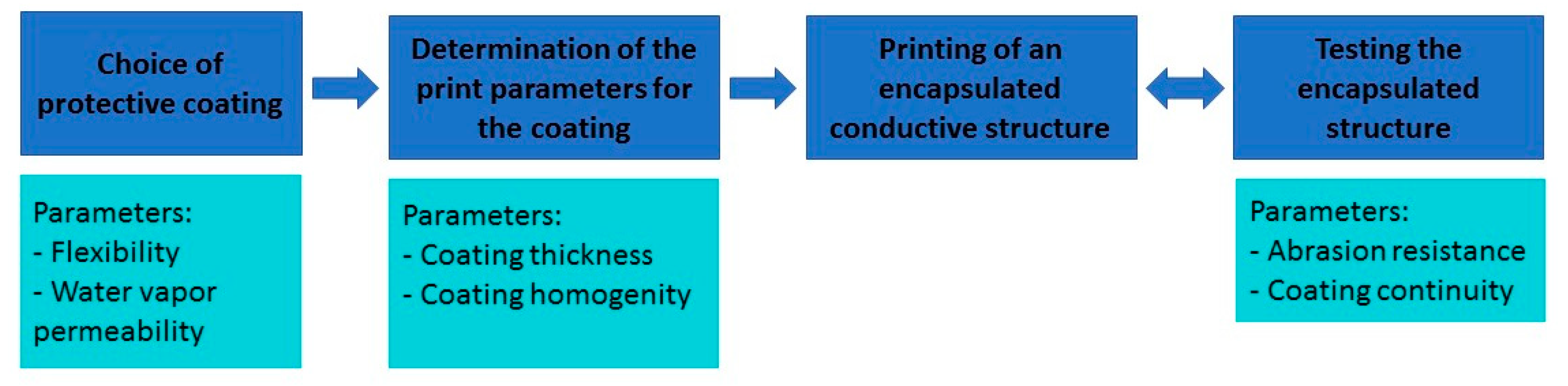
The methodology applied to this study is described in
Figure 1. First of all, a polymer containing layered silicates was chosen, depending on its flexibility and its water vapor permeability, to be used as protection for a printed conductive structure. Then, printing parameters were determined to apply the chosen polymer as a homogenous layer. These parameters were used to print an encapsulated multilayered conductive structure, and the structure’s abrasion resistance as well as the continuity of the protection layers were tested. Depending on the results, new multilayered samples were printed.
2.2. Choice of the Protective Coating
2.2.1. Water Vapor Permeability of the Diffusion-Inhibiting Protective Barrier Layer
The water vapor permeability was determined according to ISO 15106 Part 3. The measurements were performed with the water vapor permeability tester WDDG from Brugger at 85 rel. h and 23 °C.
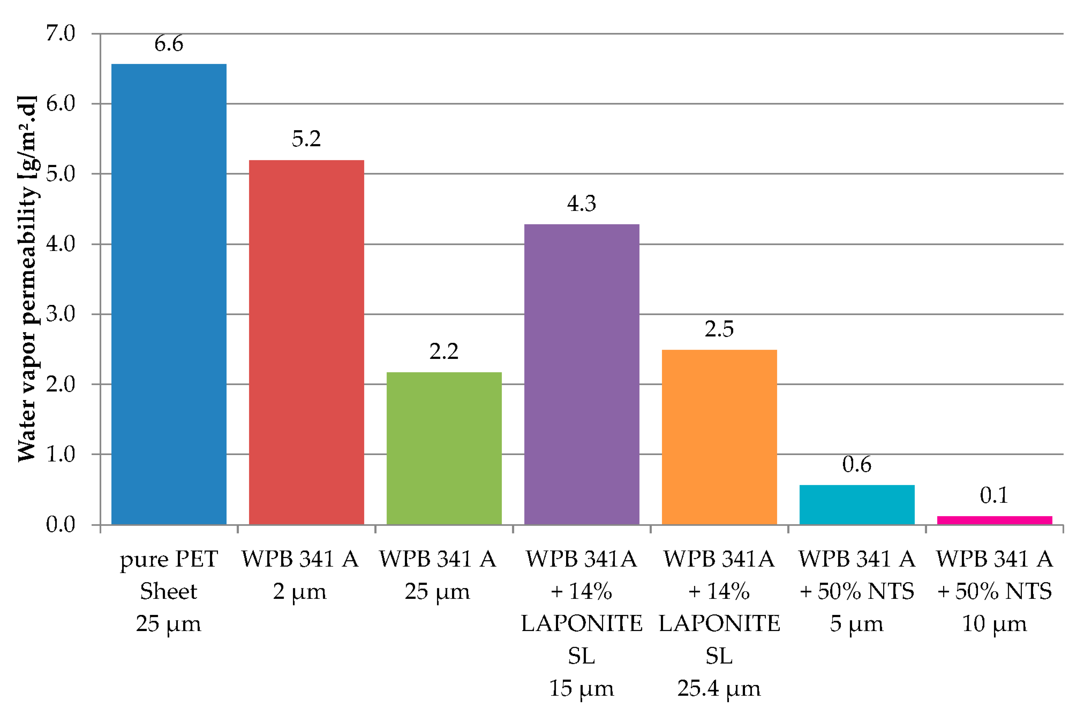
The water vapor permeabilities were measured on thin polymeric films applied on a polyester sheet with a thickness of 25 µm. The pure PET sheet had a water vapor permeability of 6.6 g/m²·d. Conforming to the diffusion model for multilayer systems—according to which the permeation resistance may be regarded as the sum of the individual resistances of the different layers—the total water vapor permeability is dominated by the more effective barrier layer.
2.2.2. Layered Silicates
Two kinds of layered silicates have been considered to reduce the water vapor permeability of the coating: LAPONITE-SL25 (BYK-Chemie GmbH) and NTS-5 (Topy industries). These liquid dispersions were mixed with the polyurethane dispersion Takelac WPB-341 A (Mitsui Chemicals), which presents sufficient water vapor barrier properties for food packaging. The addition of LAPONITE-SL25 resulted in a significant increase in the viscosity of the mixture. For this reason, the amount of LAPONITE added remained at 14% whereas NTS was added at about 50%. A thin film of each mixture was applied on a PET sheet, and its water vapor permeability was measured.
According to
Figure 2, the addition of NTS layered silicates strongly reduced the water vapor permeability of the dried film beneath 1 g/m
2 d and confirmed that layered silicates can be used to improve barrier properties. On the other hand, the addition of these layered silicates caused the film to become much more brittle and to require a long drying time, which reduces its suitability with smart textiles applications or with an economically viable printing process. The addition of LAPONITE layered silicates did not have a significant impact on the water vapor permeability of the dried film, but nevertheless affected screen-printing rheological paste properties and managed to form a flexible film with a reasonable drying time. For this reason, LAPONITE-SL25 layered silicates were further used in this study.
2.3. Printing Process
2.3.1. Printed Materials
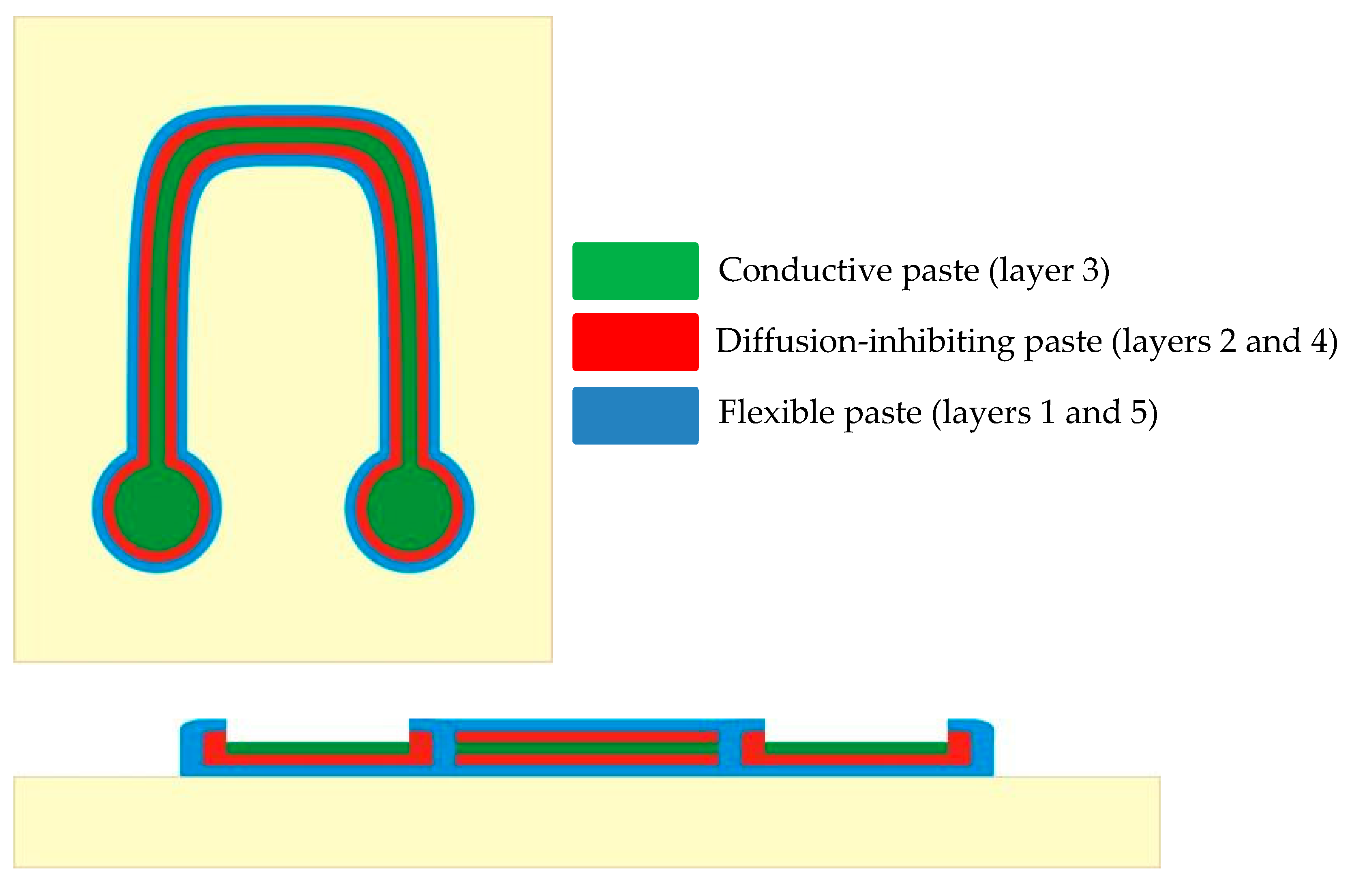
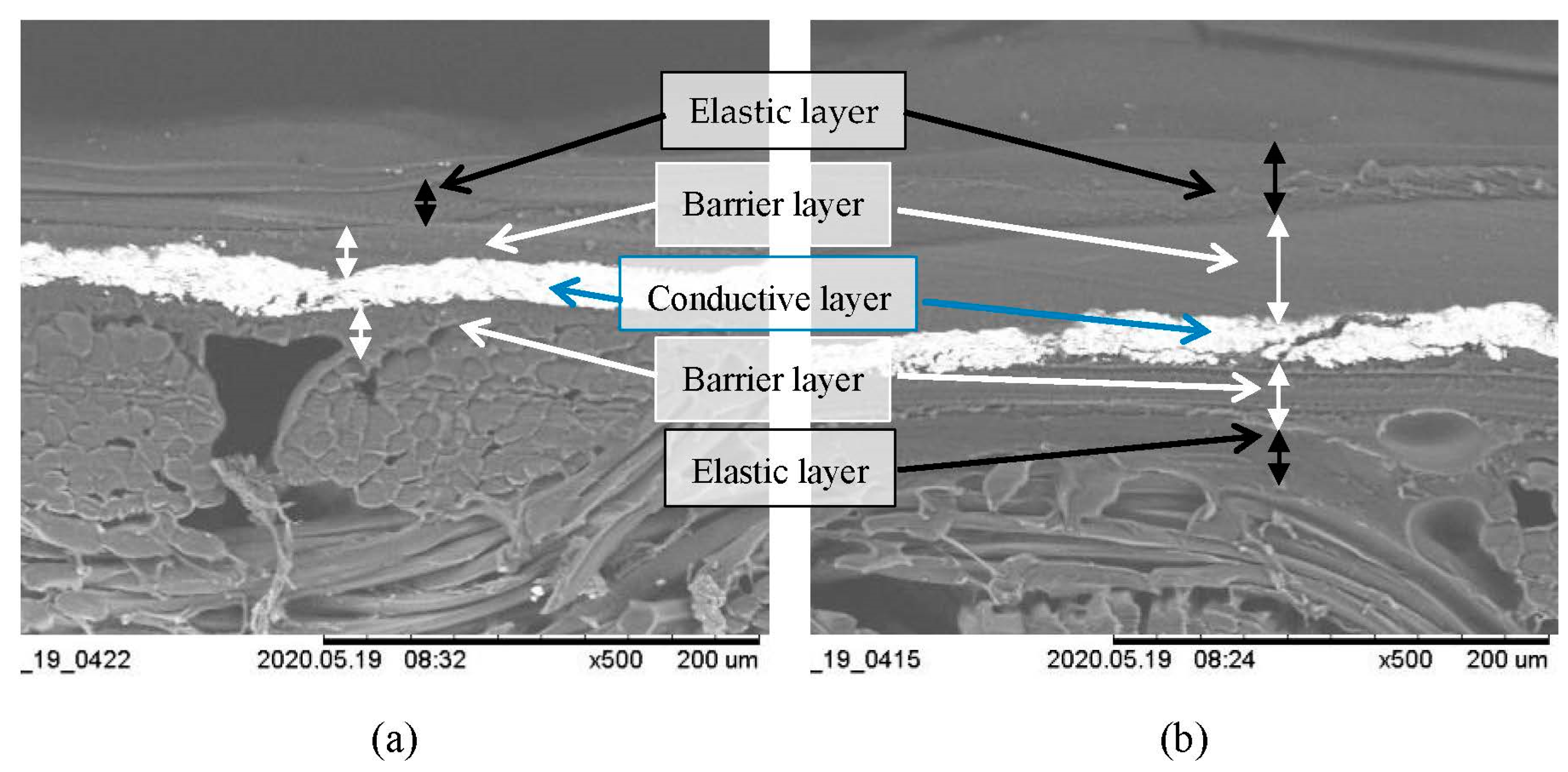
To efficiently protect a conductive pattern, it was encapsulated with two protective layers. Thus, the printed sample was made up of five layers (
Figure 3). The first and fifth layers served as a flexible primer and topcoat using the soft polyurethane Takelac WS 5000 (Mitsui) combined with layered silicates LAPONITE-SL25 (BYK), acting as an intermediate layer between a flexible textile and a rigid barrier layer to protect the whole system from damage. The second and fourth layers were barrier layers, and were mainly composed of the rigid polyurethane Takelac WPB-341A (Tg 115 °C) combined with the soft polyurethane Takelac WS 5000 (Tg 65 °C) and LAPONITE-SL25 layered silicates as well as with a thickening agent Rohagit SD 9523. The third layer was the conductive structure, composed of the silver-containing paste 200-05 (Dico Electronic). The composition of the protective layers is detailed in
Table 1.
For each printing step, the flow curve of the paste—and thus its rheological behavior under shear forces—was measured with an Anton Paar MCR 301 rotary rheometer. Both pastes used as protective layers had a viscosity of between 30 and 90 Pa.s at a shear rate of 10 s−1. The conductive paste showed a higher viscosity of 239 Pa.s at a shear rate of 10 s−1.
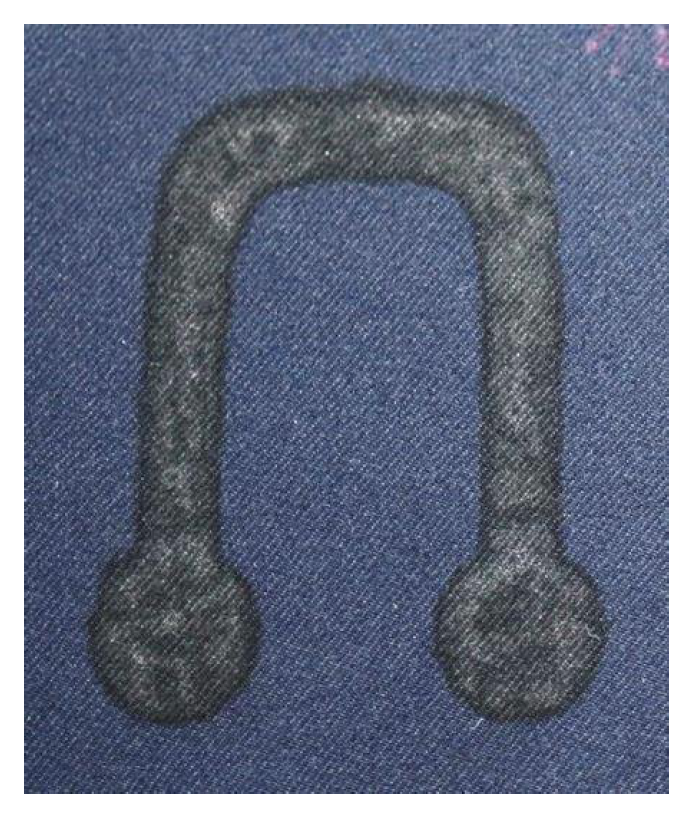
2.3.2. Print Pattern
A U-shaped pattern with two contact surfaces was designed to test the protective properties of the coating. For each coating step, we carefully kept the contact spots free of coating. The layers were printed on a polyester weaving fabric. Layer 1 was in contact with the fabric. Layer 5 was printed last.
2.3.3. Screen-Printing Technology
Protective layers as well as the conductive structure were applied by screen-printing. For this, we used a Schenk Variprint Easy screen-printing carousel with three different print stations equipped with a polyester mesh 32–100 PW and 8 aluminum pallets
The screen-printing process first consists of a flooding step followed by a printing step. During the flood stroke, the lifted mesh of the stencil is filled with paste without being in contact with the substrate. During the printing stroke, the paste in the screen is then transferred to the substrate. This process makes it possible to print an exactly defined amount of paste on a textile.
Before printing the whole protected conductive structure, we determined the optimum print parameters for the protective layers using a response surface method experimental design. Because both protective polymer dispersions had a similar rheological behavior, only the flexible paste was used to determine the print parameters. To limit the number of tests, the following printing parameters were fixed on the basis of existing preliminary tests and experience [
25,
26,
27]:
- -
Flood bar angle: Usually, a squeegee angle of 75° is used.
- -
Squeegee pressure during flooding: 1.5 bar.
- -
Flooding speed: 10 mm/s.
- -
Flood bar type: aluminum.
- -
Printed paste: paste for the flexible layer. All the protective pastes have a similar viscosity. It is expected that the parameters determined for the flexible layer can also be applied to the diffusion-inhibiting paste.
- -
The influence of the following parameters on the printing process was investigated:
- -
Off-contact distance: 2–6 mm. A jump of 2 mm ensures that the screen fabric does not come into contact with the substrate during flooding. For jumps larger than 6 mm, very high squeegee pressures are required to bring the screen fabric into contact with the substrate during printing. This could damage the screen fabric.
- -
Squeegee hardness: 80 Shore (hard), 60 Shore (soft). Squeegee hardness influences the amount of paste applied to the substrate. A soft squeegee usually applies more paste.
- -
Squeegee pressure during printing: kissing-print + 0–0.5 bar. The kissing-print corresponds to the pressure required for punctual contact of the screen fabric with the substrate. This pressure is highly dependent on the off-contact distance (
Table 2). Therefore, only the additional pressure to the kissing-print was considered in the experimental design.
- -
Squeegee speed during printing: 10–30 mm/s. The speed of the printing squeegee influences the amount of material applied to the substrate and the print quality, among other things.
The paste quantity, the homogeneity of the layers and the print quality (complete print) were defined as target values and were optically evaluated in order to determine the quality of the samples. A statistically significant model was created for each target figure. A total of 40 trials were carried out to determine the print parameters.
2.3.4. Drying Process
After each print, a drying process was performed with a QC 5050 MW medium wave flash cure dryer (Calmat). The optimum drying parameters were determined in another study on the basis of design of experiments [
28]. A drying time of 99 s and the IR-Radiator power P04 were used to dry all pastes without damaging the fabric.
2.4. Testing
2.4.1. Pinhole Test
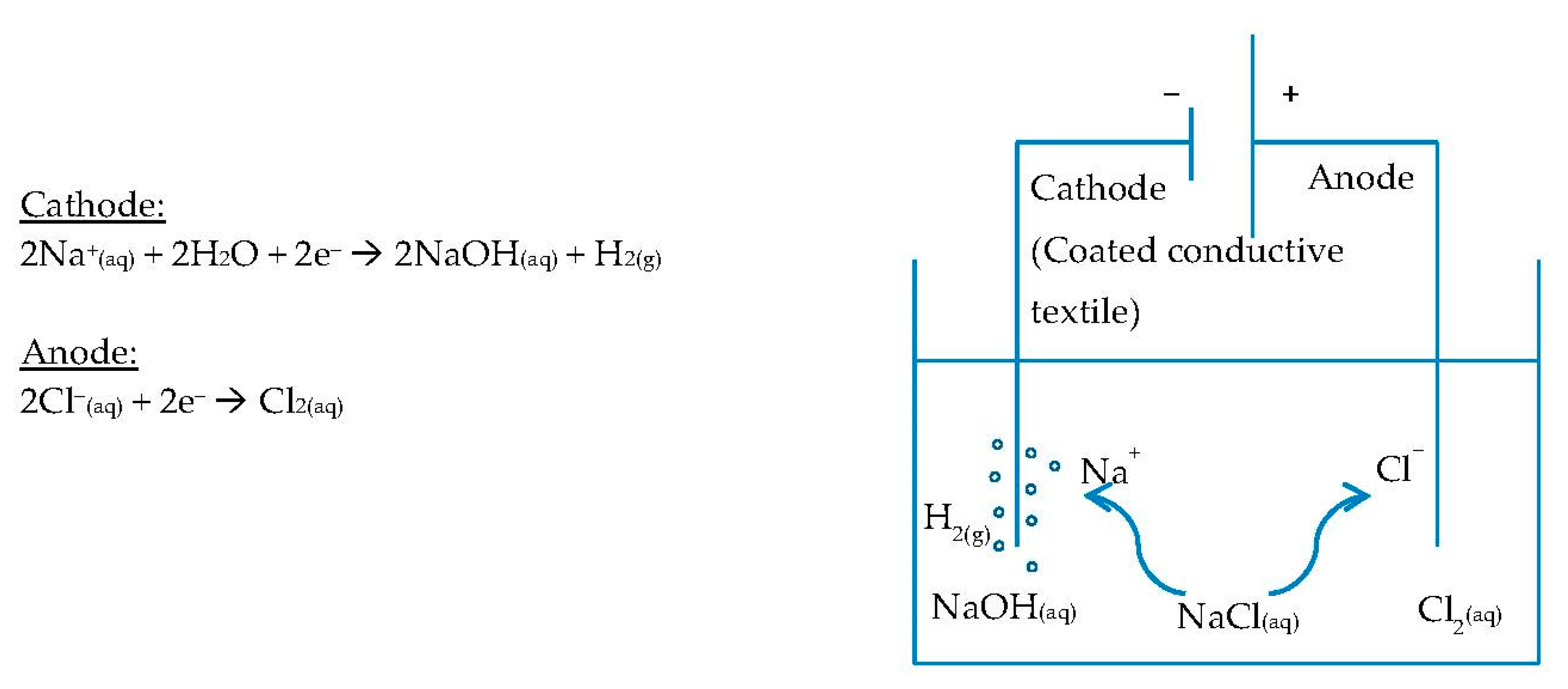
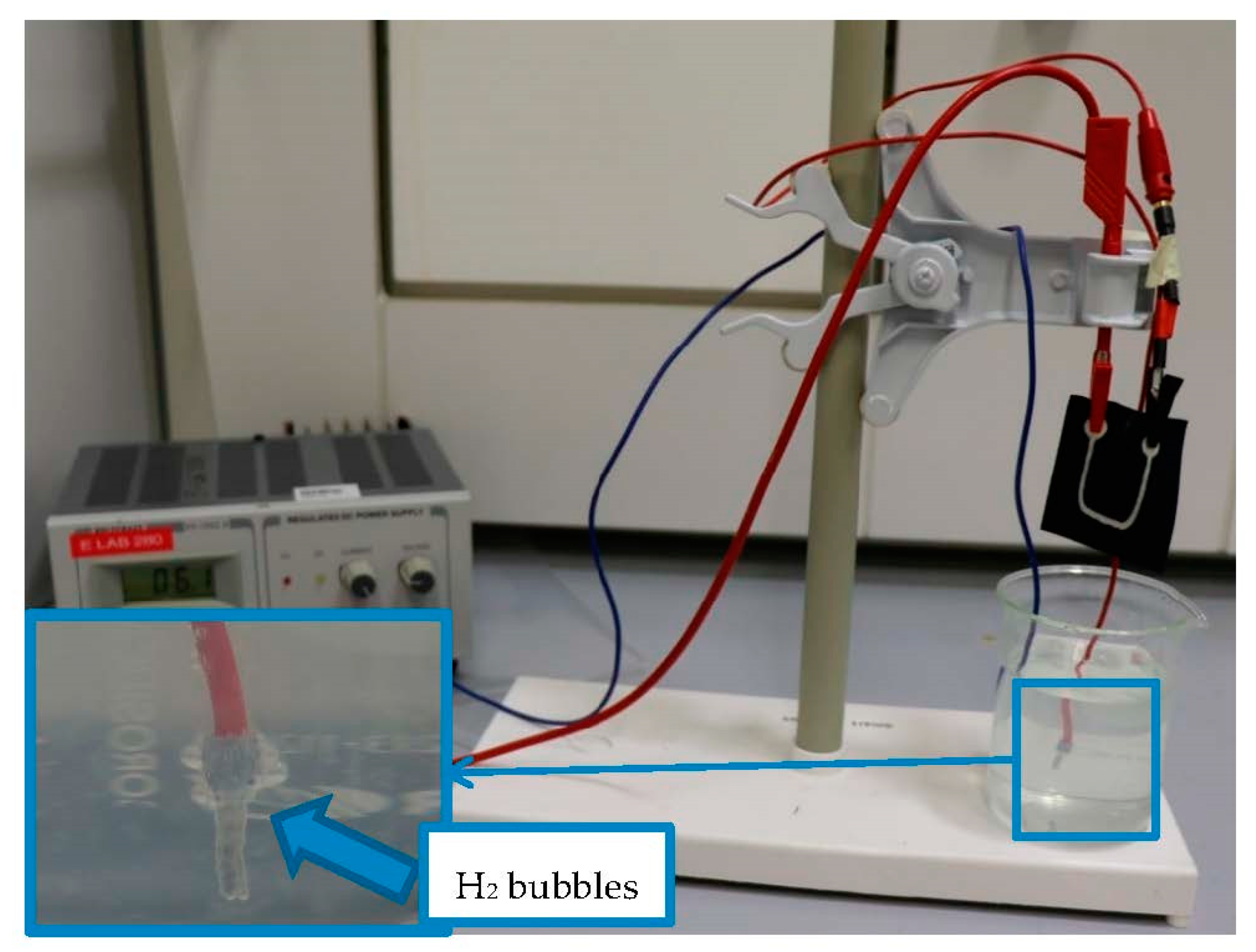
In order to check the continuity of the protective layers, a pinhole test was performed with the printed samples. Electrolysis of an NaCl solution was performed using the coated conductive textile as cathode (
Figure 4). A standard microcable was used as anode.
The following electrochemical reactions took place at the electrodes when current flowed.
This method enables visible detection of any pinhole or crack in the coating through the formation of H2 bubbles in the uncoated areas. The formation of hydrogen bubbles was assessed qualitatively but not quantitatively.
Prior to testing, we checked that current could flow through the print conductive path. One side of the conductive pattern was connected with a voltage supply. The other side of the pattern was connected with a standard microcable, whose stripped end was immersed in the NaCl solution as well as the anode. By increasing the voltage, H
2 bubbles should occur at the stripped end of the microcable (
Figure 5).
Because the conductive layer of the print pattern contains silver particles, the voltage was applied before the print pattern was immersed in the saline solution to protect the silver particles from oxidation.
2.4.2. Scanning Electron Microscopy (SEM)
SEM images were obtained with a Hitachi Tabletop Microscope TM-1000 in order to observe the structure of the printed layers and any disruption in the coating. SEM microscopy was used in addition to the pinhole test to check the continuity of the applied layers.
2.4.3. Abrasion Resistance
The abrasion resistance was evaluated with a Martindale abrasion tester according to the standard DIN EN ISO 12947 part 2 and 4.
Two samples with conductive pattern and without protective coating as well as two samples with protective coating were conditioned under 65% rel. h. and 20 °C for 24 h and then tested simultaneously. The samples were first loaded with 9 kPa and scrubbed with a standard scouring wool fabric at a scrubbing speed of 3000 T/min. After 50,000 rubbing tours, the load was increased to 12 kPa.
3. Results
3.1. Determination of Printing Parameters for the Protective Layers
The results of the experimental design are shown in
Table 3. The best results were obtained with a small off-contact distance of >2 mm. To obtain a homogeneous layer, a slow squeegee speed and high squeegee pressure was required.
Printing tests were carried out with these parameters (
Figure 6), and they confirmed the results of the experimental design.
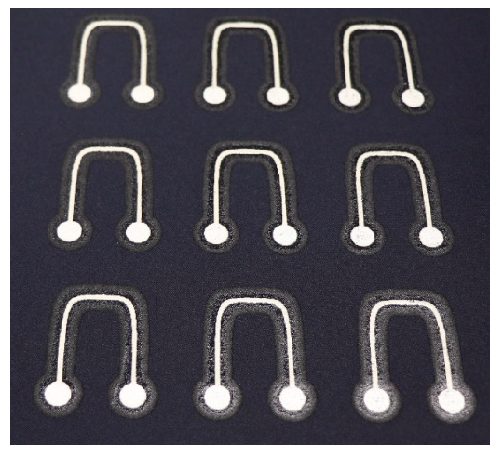
3.2. Printed Samples for Testing
Multilayered conductive samples were printed in a single process using the printing parameters determined previously for the five layers (
Table 4). In order to characterize the properties of the obtained sample, nine samples were printed simultaneously. Each sample was then used to carry out a specific test (e.g., pinhole test, abrasion test or SEM microscopy). In this way, the influence of external conditions such as temperature or humidity did not affect the results obtained. The resulting printing is shown in
Figure 7. No differences could be observed visually between the samples.
3.3. Tests
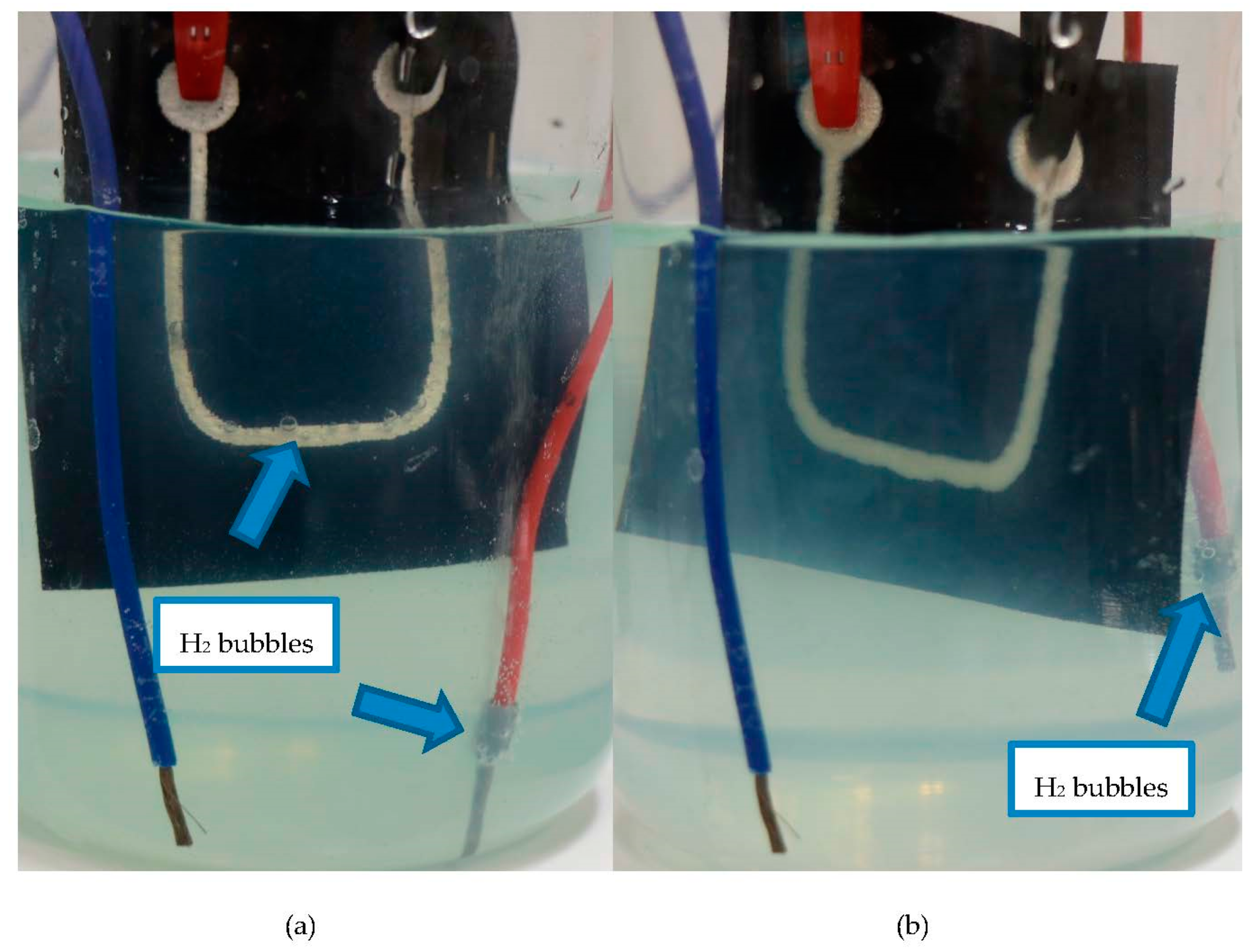
3.3.1. Pinhole Test
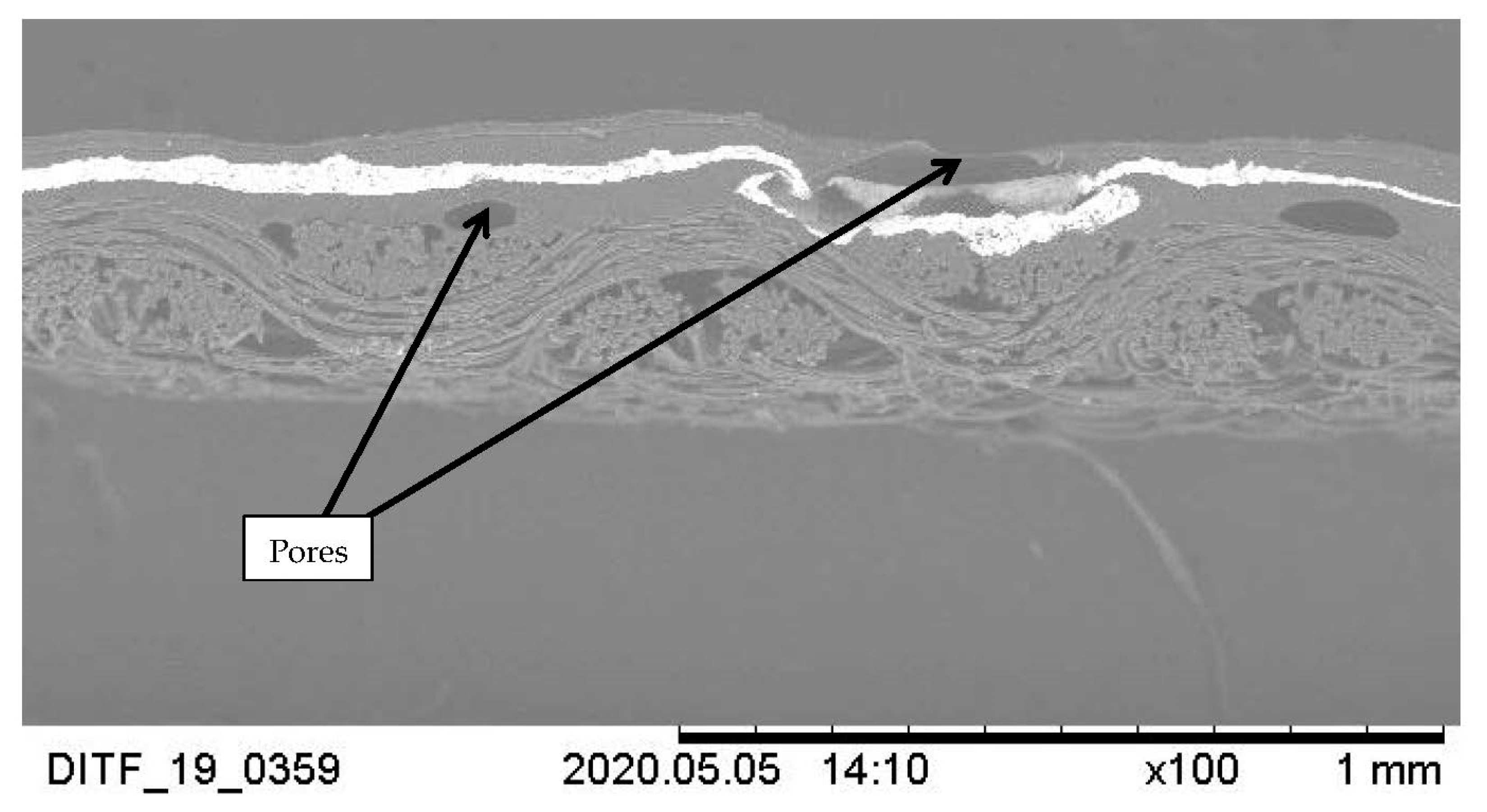
In the first print sample tested, the respective protective layers and the conductive layer were each printed once as single layers. During the pinhole test, hydrogen bubbles formed on the surface of the print sample (
Figure 8a), which can be explained by a hole in the protective coating. This was confirmed by SEM images, which showed the presence of pores in the protective layers (
Figure 9).
To improve the barrier properties of the coating, protective layers were printed twice (double layer) to increase their thickness (
Figure 10) and thus minimize the presence of continuous pores in the coating. In this case, the formation of hydrogen bubbles on the surface of the printed sample could not be detected during the pinhole test (
Figure 8b). These results suggest that the developed diffusion-inhibiting pastes can be applied to textiles by screen-printing as flexible protection for conductive patterns, and thus suggest that the pastes can be implemented in the fabrication of smart textiles.
3.3.2. Martindale Abrasion Test
A Martindale abrasion test was performed to evaluate the abrasion resistance of the developed protective coating according to the parameters described in
Section 2.4.3. The results of the test are shown in
Table 5.
A slight abrasion of the conductive pattern of the uncoated samples was observed after only 610 cycles. After 50,000 abrasion cycles with a load of 9 kPa, no significant change could be detected in the coated samples. These samples were then loaded with 12 kPa and scrubbed again. After an additional 35,000 cycles, a hole was formed in the uncoated areas. However, the coated area remained unchanged. These results suggest that the developed coating system can be used as efficient protection from abrasion for printed conductive patterns.
4. Discussion
4.1. Abrasion Resistance
The samples with uncoated printed conductive patterns showed a low abrasion resistance. Because of its high viscosity, the conductive paste remained at the surface of the fabric, enabling a high conductivity of the structure after printing. However, as demonstrated by Kazani et al. [
29], the conductive structure was thereby more sensitive to abrasion. In the study performed by Kazani et al., a conductive pattern was screen-printed on different fabrics, and its abrasion resistance and washability were tested. For this, the square resistance was measured before and after 5000 abrasion cycles. A clear increase of the square resistance was observed after abrasion. To improve the washability of the printed fabrics in the study by Kazani et al., the conductive patterns were laminated with an 80 µm thermoplastic polyurethane film. This should also improve the abrasion resistance, even if it was not tested in their study. However, the use of a film twice as thick as the coating obtained by screen-printing in our study limits the flexibility of the textile, and it especially requires an additional process to produce the smart textile, which makes the manufacturing process less economically viable.
Although our encapsulated structure also remained at the surface of the fabric, as seen in
Figure 10, it showed a very high abrasion resistance. A Martindale abrasion test proved that a layer with a total thickness of approximately 20–40 µm of the developed coatings efficiently protected conductive patterns from abrasion. The coating can only be damaged by higher loads up to 12 kPa and more cycles than 85,000. This can be explained not only by the use of polyurethane—known for its good abrasion resistance—but also by the presence of layered silicates in the coating. Tabsan et al. [
30] showed that adding a small amount of layered silicates (3 phr) in a rubber highly improved its abrasion resistance. To confirm this, abrasion tests should be performed with a similar TPU coating without layered silicates.
4.2. Barrier Properties
In a similar work [
31], a conductive structure was encapsulated with two polyurethane layers. The first layer had waterproof properties. The second layer had adhesive properties to prevent the conductive layer from cracking. The thickness of the printed coating (90 µm) was similar to our coating (70–80 µm), even if it required four printing steps instead of the two steps in our case. However, the coating’s water vapor permeability was not studied, so it remains unclear whether these coatings efficiently protected the conductive structure from water. Because water vapor barrier properties were not mentioned by Yang et al., we predict that the water vapor permeability of their coating is higher than the water vapor permeability of the coatings used in our study. In this case, the risk of damaging the conductive structure by oxidation would be higher.
To date, no coatings with a low water vapor permeability have been used as printed layers to protect smart textiles.
4.3. Improvement of the Coating
Due to the formation of pores during the printing/drying processes, a single coating step did not effectively protect the printed conductive layer. This could also explain the relatively high water vapor permeability measured with the single-layer coatings containing LAPONITE layered silicates.
By repeating the printing process and thus applying a thicker protective coating (70–80 µm), the likelihood of pore formation was reduced. In this case, a pinhole test showed that a continuous coating was obtained on the printed conductive pattern. It can therefore be concluded that polyurethane dispersions mixed with layered silicates are suitable for the protection of printed smart textiles as long as the pore formation during the printing process is limited.
The formation of these pores could be due to:
- -
The elimination of the water present in the dispersion during the drying process, especially if the drying temperature exceeds 100 °C too early; or
- -
Air entrapment during the printing process and paste preparation.
In addition to avoiding the formation of gas bubbles by modifying the printing and drying parameters, it is possible to promote their removal.
According to Stokes’ law (Equation (1)), the rising speed of the bubbles depends on the dynamic viscosity of the coating, among other things.
where:
v the rising speed of the bubble (m/s);
g is the gravitational field strength (m/s²);
R is the radius of the gas bubble (m);
ρp is the mass density of the particles (kg/m³);
ρf is the mass density of the fluid (kg/m³);
μ is the dynamic viscosity of the coating (kg/(m × s)).
A reduction in the solid content in the dispersion (and therefore a reduction in its viscosity) could improve the evacuation of gas bubbles and thus the barrier properties.
The use of defoamer or de-aerator additives in the composition of the coating should also be tested to avoid the formation of pores. In this way, one could expect to obtain the same barrier properties with even thinner coatings.
5. Conclusions
In this study, polyurethane dispersions were mixed with LAPONITE-SL25 layered silicates to obtain screen-printing pastes with low water vapor permeability. The screen-printing technology is suitable to apply these dispersions as a thin continuous coating. By applying a multi-layer coating made up of a rigid layer with high diffusion-inhibiting properties and a flexible layer, on and under a conductive structure, we were able to efficiently protect it from mechanical and chemical stresses like abrasion and oxidation. The use of screen-printing enables a cost-effective application of these coatings on conductive structures with complex geometries.
It is conceivable to reduce the thickness of the coating while maintaining its barrier properties as long as the formation of pores during the printing/drying process is limited.
While these coatings have proven to be effective in protecting printed structures, they could also be used to protect conductive textile structures with complex geometries such as embroidery, knitted and weaving fabrics. These coatings are therefore suitable for use in the interdisciplinary field of smart textiles.
Author Contributions
V.B.: scientific design of the process development (printing, testing), implementation and analysis of the screen-printed samples and tests, original writing and proof reading of manuscript; V.v.A.: scientific design of material development (coatings), implementation and analysis of developed coatings, co-writing and proof reading of manuscript; S.K.: implementation and analysis of the screen-printed samples; M.H.: proof reading of manuscript; T.S.: funding acquisition, project supervision, proof reading of manuscript; G.T.G.: proof reading of manuscript. All authors have read and agreed to the published version of the manuscript.
Funding
This research was funded via the AiF as part of the program to promote joint industrial research (IGF) by the German Federal Ministry of Economics and Energy. Grant number 19734.
Institutional Review Board Statement
Not applicable.
Informed Consent Statement
Not applicable.
Data Availability Statement
The data presented in this study are available on request from the corresponding author.
Acknowledgments
My special thanks go to all my colleagues at the DITF who were involved in this research project for their friendly and efficient cooperation.
Conflicts of Interest
The authors declare no conflict of interest.
References
- Grand View Research. Smart Fabrics Market Size, Share & Trends Analysis Report By Product (Active, Very Smart), By End Use (Defense & Military, Sports & Fitness), By Functionality (Sensing, Energy Harvesting), and Segment Forecasts, 2019—2025; Grand View Research: San Francisco, CA, USA, 2019. [Google Scholar]
- Hofmann, P.; Walch, A.; Dinkelmann, A.; Selvarayan, S.K.; Gresser, G.T. Woven piezoelectric sensors as part of the textile reinforcement of fiber reinforced plastics. Compos. Part A Appl. Sci. Manuf. 2019, 116, 79–86. [Google Scholar] [CrossRef]
- Kongahage, D.; Foroughi, J. Actuator Materials: Review on Recent Advances and Future Outlook for Smart Textiles. Fibers 2019, 7, 21. [Google Scholar] [CrossRef]
- Schneider, R.; Frick, S.; Lenz, A.; Caydamli, Y.; Arnold, P. Textile-Based Sensors for Inspection of Composite Materials. J. Mater. Sci. Eng. B 2020, 10, 74–83. [Google Scholar]
- Dias, T. Electronic Textiles; Woodhead Publishing: Cambridge, UK, 2015. [Google Scholar]
- Möhring, U. Textile Mikrosysteme im Automobil. In Technische Textilien; Deutscher Fachverlag: Frankfurt am Main, Germany, 2006; pp. 317–336. [Google Scholar]
- Bao, Z.; Feng, Y.; Dodabalapur, A.; Raju, V.R.; Lovinger, A.J. High-Performance Plastic Transistors Fabricated by Printing Techniques. Chem. Mater. 1997, 9, 1299–1301. [Google Scholar] [CrossRef]
- Bock, K. Polymer Electronics Systems—Polytronics. Proc. IEEE 2005, 93, 1400–1406. [Google Scholar] [CrossRef]
- Marra, F.; Minutillo, S.; Tamburrano, A.; Sarto, M.S. Production and characterization of Graphene Nanoplatelet-based ink for smart textile strain sensors via screen printing technique. Mater. Des. 2021, 198, 109306. [Google Scholar] [CrossRef]
- Ferri, J.; Llopis, R.L.; Moreno, J.; Ibáñez, J.; Garcia-Brejio, E.; Civera, I.; Breijo, G. A Wearable Textile 3D Gesture Recognition Sensor Based on Screen-Printing Technology. Sensors 2019, 19, 5068. [Google Scholar] [CrossRef] [PubMed]
- Tseghai, G.; Malengier, B.; Fante, K.; Nigusse, A.; Van Langenhove, L. Development of a Flex and Stretchy Conductive Cotton Fabric Via Flat Screen Printing of PEDOT:PSS/PDMS Conductive Polymer Composite. Sensors 2020, 20, 1742. [Google Scholar] [CrossRef] [PubMed]
- Qu, J.; He, N.; Patil, S.V.; Wang, Y.; Banerjee, D.; Gao, W. Screen Printing of Graphene Oxide Patterns onto Viscose Nonwovens with Tunable Penetration Depth and Electrical Conductivity. ACS Appl. Mater. Interfaces 2019, 11, 14944–14951. [Google Scholar] [CrossRef] [PubMed]
- Åkerfeldt, M.; Strååt, M.; Walkenström, P. Electrically conductive textile coating with a PEDOT-PSS dispersion and a polyurethane binder. Text. Res. J. 2012, 83, 618–627. [Google Scholar] [CrossRef]
- Gnewuch, K. Chromojet—The innovative technology for printing of conductive structures on textile. In Proceedings of the 54th Dornbirn Man-Made Fibers Congress, Dornbirn, Austria, 16–18 September 2015. [Google Scholar]
- Stoppa, M.; Chiolerio, A. Wearable Electronics and Smart Textiles: A Critical Review. Sensors 2014, 14, 11957–11992. [Google Scholar] [CrossRef] [PubMed]
- Elschner, A. PEDOT Principles and Applications of an Intrinsically Conductive Polymer; CRC Press: Boca Raton, FL, USA, 2011. [Google Scholar]
- Krebs, F.C. Degradation and stability of polymer and organic solar cells. Sol. Energy Mater. Sol. Cells 2008, 92, 685. [Google Scholar] [CrossRef]
- Glover, C.F.; McGettrick, J.; Williams, G.D.; Watson, T.; Bryant, D. A Scanning Kelvin Probe Investigation of the Interaction of PEDOT: PSS Films with Metal Surfaces and Potential Corrosion Protection Properties. J. Electrochem. Soc. 2015, 162, H799–H805. [Google Scholar] [CrossRef]
- Vitoratos, E. Conductivity Degradation Study of PEDOT: PSS Films under Heat Treatment in Helium and Atmospheric Air. Open J. Org. Polym. Mater. 2012, 2, 7–11. [Google Scholar] [CrossRef]
- Langowski, H.-C. Anwendung der Nanotechnologie in Materialien für den Lebensmittelkontakt. 2006. Available online: https://www.bfr.bund.de/de/a-z_index/nanotechnologie-7585.html (accessed on 12 November 2020).
- Khajavi, M.Z.; Ebrahimi, A.; Yousefi, M.; Ahmadi, S.; Farhoodi, M.; Alizadeh, A.M.; Taslikh, M. Strategies for Producing Improved Oxygen Barrier Materials Appropriate for the Food Packaging Sector. Food Eng. Rev. 2020, 12, 346–363. [Google Scholar] [CrossRef]
- Hargarter, N.; Kliewer, U.; Kosthorst, H.; Stenbeck, W. Membranfolie für Biogasanlagen. German Patent DE102008048898 A1, 25 September 2008. [Google Scholar]
- Houssier, D.; Teniers, C. Eval (EVOH) und TPU für sehr Flexible Barriere-Folien. PU Magazin 2005, 06, 264–267. [Google Scholar]
- Penaloza, D.P. Enhanced mechanical, thermal and barrier properties of clay-based polymer nanocomposite systems. Epa. J. Silic. Based Compos. Mater. 2019, 71, 74–79. [Google Scholar] [CrossRef]
- Linti, C.; Loy, S.; Horter, H.; Planck, H. Smart Textiles für das ambulante Monitoring von kardio-respiratorischen Krankheiten. In Proceedings of the 48th Dornbirn Man-Made Fibers Congress, Dornbirn, Austria, 16–18. September 2009; pp. 1–12. [Google Scholar]
- Linti, C.; Horter, H.; Österreicher, P.; Planck, H. Sensory baby vest for the monitoring of infants. In Proceedings of the International Workshop on Wearable and Implantable Body Sensor Networks (BSN’06), Cambridge, MA, USA, 3–5 April 2006; pp. 135–137. [Google Scholar]
- Sefar, A.G. Siebdruckhandbuch; Sefar Printing Division, 2009. [Google Scholar]
- DITF, IGF 19734: Dehnbare, Diffusionshemmende Beschichtungen für Textilintegrierte, Textilbasierte Elektrische Strukturen. 2020. Available online: https://www.ditf.de/de/index/aktuelles/kurzveroeffentlichungen.html?year=2020 (accessed on 11 November 2020).
- Kazani, I.; Hertleer, C.; De Mey, G.; Schwarz, A.; Guxho, G.; Van Langenhove, L. Electrical Conductive Textiles Obtained by Screen Printing. Fibres Text. East. Eur. 2012, 20, 57–63. [Google Scholar]
- Tabsan, N.; Wirasate, S.; Suchiva, K. Abrasion behavior of layered silicate reinforced natural rubber. Wear 2010, 269, 394–404. [Google Scholar] [CrossRef]
- Yang, K.; Torah, R.; Wei, Y.; Beeby, S.; Tudor, J. Waterproof and durable screen printed silver conductive tracks on textiles. Text. Res. J. 2013, 83, 2023–2031. [Google Scholar] [CrossRef]
| Publisher’s Note: MDPI stays neutral with regard to jurisdictional claims in published maps and institutional affiliations. |
© 2021 by the authors. Licensee MDPI, Basel, Switzerland. This article is an open access article distributed under the terms and conditions of the Creative Commons Attribution (CC BY) license (http://creativecommons.org/licenses/by/4.0/).

 ,
, 


