Innovative Turbine Intake Air Cooling Systems and Their Rational Designing
by
Andrii Radchenko
1, 
Eugeniy Trushliakov
1,
Krzysztof Kosowski
2,
Dariusz Mikielewicz
2,* and
Mykola Radchenko
1 1
Department of Ship Electroenergetic Systems, Admiral Makarov National University of Shipbuilding, Heroes of Ukraine Avenue 9, 54000 Mykolayiv, Ukraine
2
Faculty of Mechanical Engineering, Gdańsk University of Technology, 80-233 Gdańsk, Poland
*
Author to whom correspondence should be addressed.
Energies 2020, 13(23), 6201; https://doi.org/10.3390/en13236201
Submission received: 15 September 2020
/
Revised: 11 November 2020
/
Accepted: 20 November 2020
/
Published: 25 November 2020
(This article belongs to the Special Issue Enhancement of Heat Transfer in Power Plants)
Abstract
:The efficiency of cooling ambient air at the inlet of gas turbines in temperate climatic conditions was analyzed and reserves for its enhancing through deep cooling were revealed. A method of logical analysis of the actual operation efficiency of turbine intake air cooling systems in real varying environment, supplemented by the simplest numerical simulation was used to synthesize new solutions. As a result, a novel trend in engine intake air cooling to 7 or 10 °C in temperate climatic conditions by two-stage cooling in chillers of combined type, providing an annual fuel saving of practically 50%, surpasses its value gained due to traditional air cooling to about 15 °C in absorption lithium-bromide chiller of a simple cycle, and is proposed. On analyzing the actual efficiency of turbine intake air cooling system, the current changes in thermal loads on the system in response to varying ambient air parameters were taken into account and annual fuel reduction was considered to be a primary criterion, as an example. The improved methodology of the engine intake air cooling system designing based on the annual effect due to cooling was developed. It involves determining the optimal value of cooling capacity, providing the minimum system sizes at maximum rate of annual effect increment, and its rational value, providing a close to maximum annual effect without system oversizing at the second maximum rate of annual effect increment within the range beyond the first maximum rate. The rational value of design cooling capacity provides practically the maximum annual fuel saving but with the sizes of cooling systems reduced by 15 to 20% due to the correspondingly reduced design cooling capacity of the systems as compared with their values defined by traditional designing focused to cover current peaked short-term thermal loads. The optimal value of cooling capacity providing the minimum sizes of cooling system is very reasonable for applying the energy saving technologies, for instance, based on the thermal storage with accumulating excessive (not consumed) cooling capacities at lowered current thermal loads to cover the peak loads. The application of developed methodology enables revealing the thermal potential for enhancing the efficiency of any combustion engine (gas turbines and engines, internal combustion engines, etc.).
1. Introduction
Fuel efficiency of combustion engines (gas turbines [1,2,3], diesel engines [4] and gas engines [5,6,7]) falls with raising an ambient air temperature at their intake. Gas turbines (GT) are especially sensitive to intake conditions [8,9,10]: a specific fuel consumption increases by 0.4 to 1.0 g/(kWh) for every 1K rise in intake air temperature. A lot of ambient air cooling technologies were developed to enhance engine output [11,12,13]. The cheapest and most widespread in hot climatic conditions is a contact method by evaporation of water sprayed into air stream at the intake of GT compressor [14] and a novel contact cooling according to Maisotsenko cycle [15,16], but their efficiency is limited by the magnitudes of ambient air wet bulb temperature and they are not so effective in temperate climatic conditions.
Meantime the GT efficiencies are typically of 30 to 35% and a major part of the fuel energy consumed is dissipated to atmosphere as exhaust gases. Therefore, the use of exhaust heat from GT is a very effective trend in enhancing their overall efficiency [17,18]. Issuing from this, turbine intake air cooling (TIAC) in exhaust heat recovery chillers is a very perspective approach to improving the fuel efficiency of GT at increased intake ambient air temperatures [19,20,21]. Thus, cooling intake air by converting the heat of exhaust gas in chillers provides increasing the efficiency of GT with corresponding fuel saving at raised ambient air temperatures [22,23,24].
The absorption lithium-bromide chillers (ACh) are the most widely used in a hot climate [25,26,27]. They are characterized by a high efficiency: their coefficients of performance COP is 0.7 to 0.8 (COP is ratio of generated cooling capacity Q0, kW, to the heat consumed Qh, kW), environmentally friendly, and noise free [28,29,30]. The same advantages and ability to use a low potential heat with a bit less COP are peculiar for adsorption chillers [31,32]. The refrigeration vapor compression chillers require mechanical or electrical driving [33], while absorption and adsorption chillers use only waste heat.
Some authors have investigated the use of ACh to improve the efficiency of contact methods of cooling, in particular by cooling the water injected into the air stream; however, the most common way of cooling air at the inlet of the GT is the application of air coolers fed by ACh cooling capacity.
Many publications focused for improving ambient air processing by intensification of heat transfer processes in air coolers-evaporators [34] and condensers [35,36,37] of refrigeration chillers, in particular, through refrigerant recirculation to intensify heat transfer, increase heat flux and reduce temperature difference in intake air coolers as result [38,39], waste heat recovery technics for combined cooling, heating and power (CCHP), so-called trigeneration or integrated energy systems [40,41].
Some of principal technical innovations and methodological approaches in heat recovery: jet technologies [42,43,44], deep exhaust heat use [45,46,47] for increasing the available waste heat potential to be converted into refrigeration and others were developed for TIAC or might be successfully applied in TIAC to match current cooling demands [48,49,50], in particular, two-stage air cooling [51].
The intake air temperature depression Δt = tamb − ta2, influencing the efficiency of TIAC, depends on the ambient air temperature tamb and a temperature ta2 of air cooled in chiller at the inlet of GT, which depends on the temperature of a coolant, i.e., on the type of chiller. In ACh of a simple cycle with high coefficients of performance COP is 0.7 to 0.8 and a temperature of chilled water tw of about 7 °C an intake air can be cooled only to ta2 = 15 °C. In the most simple in design and cheap refrigeration ejector chillers (ECh) that use refrigerants as low boiling coolant, the intake air can be cooled to lower temperatures ta2 is 7 to 10 °C at the temperatures of boiling refrigerant t0 ranging from 1 to 5 °C, but with low COP from 0.2 to 0.3 that requires raised amounts of exhaust gas heat.
It is quite reasonable to apply a highly efficient ACh as a high-temperature stage of intake air cooling from current ambient air temperatures tamb to ta2 = 15 °C and a less efficient ECh as a low-temperature stage for further subcooling air lower than 15 °C. The application of such hybrid intake air coolers is especially expedient for operation of GT in temperate climatic conditions. They are able to provide deep intake air cooling with corresponding increase of TIAC operation duration and much more annual effect as a result: fuel reduction or power output increase, compared to traditional cooling in ACh.
Such innovative two-stage ambient air cooling systems consist of chillers that convert the heat of exhaust gas into refrigeration in the form of coolant, feeding turbine intake air coolers, and could find effective application in different types of combustion engines: gas turbines [52,53], gas engines for combustion of biogas [54,55], stationary and marine power plants [56,57].
Many modern methods of analyses [58,59,60] are aimed to increase the effect gained due to ambient air processing, in particular, to reduce energy and fuel consumption. Some of such methods include calculation of cooling degree-hours (CDH) [14,61] and modified versions [62,63,64] to match current cooling duties according to actual climatic conditions as well as thermal demand management (TDM) [65,66] based on different criteria [67,68] to save energy in building conditioning, engine intake air cooling and combined cooling, heat and power.
Cooling degree-hour (CDH) calculations are widely used for evaluating the efficiency of application of ambient air cooling in site climatic conditions in power generation—combustion engine intake air cooling [63,64], as well as in air conditioning [62]. So as the performance efficiency of TIAC systems needs to be analyzed across the full range of operating conditions, the CDH number is used to determine the total amount ∑CDHs in a particular climate over a considered period.
The use of TIAC potential in terms of CDH provides easy calculation of fuel reduction and engine power output augmentation for any considered period. For this purpose a climatic characteristic of GT as dependence of specific fuel consumption be, g/(kWh), and GT power output Pe, kW, on intake air temperature are used.
The ambient air temperature and relative humidity distribution during year or any cooling period is very important input data for energy analyses and a design cooling load determination. The studies on the input ambient data when evaluating gas turbine inlet cooling are presented in [62,63,64].
Although many researchers consider the cumulative CDH profile along with time elapsed [62], only a few studies focus on analyzing the behavior of yearly cumulative cooling profiles in dependence on loading to determine a design cooling load [63,65].
All the typical methods, based on summarizing the number of CDH, issue from the assumption of a design cooling capacity as a sufficient to provide maximum cooling needs over the full range of yearly operating conditions [63]. Such an approach may lead to considerable oversizing of the chillers and the TIAC systems in the whole that requires to solve the problem of determining the correct design cooling load excluding oversizing, as it was shown in [69,70,71].
A design cooling capacity Q0 of TIAC system, on the one hand, has to cover intake air cooling, and needs to do so during as long a time of GT operation during a year as possible, which provides the greatest annual fuel reduction. On the other hand, a design cooling capacity Q0 should not be overestimated so that for the most part of the year a TIAC system would be able to operate at a high load level close to a design value. Otherwise low efficiency of TIAC system operation takes place, and on the contrary, when underestimating Q0—insufficient turbine intake air cooling at high ambient temperatures.
Thus, the fuel efficiency of GT in temperate climatic conditions firstly might be considerably enhanced due to deep intake air cooling that needs the application of combined chillers and rational designing of TIAC systems to guarantee a close to maximum annual fuel saving, but without system overloading, as an alternative to their traditional designing to cover the maximum loading with inevitable system oversizing.
The goal of this investigation is to increase the fuel efficiency of GT by deep intake air cooling in combined absorption ejector TIAC systems with ACh as a high-temperature and ECh as a low-temperature cooling stages and through rational designing of the proposed systems.
2. Materials and Methods
A method of logical analysis [72,73] of the actual operation efficiency of TIAC systems in real varying environment, supplemented by the simplest numerical simulation that enables its easy application in designing practice of any ambient air cooling system, is behind this research and the design methodology proposed. The real input data on site actual climatic conditions (ambient air temperature tamb and relative humidity ) were taken by using the well-known programs, for instance “meteomanz” [74].
To avoid errors caused by the approximation of the current changeable effect gained due to cooling (fuel reduction, power output increase, etc.) at varying loading of TIAC systems in response to actual climatic conditions, the fluctuations of the last are considered through summarizing the current values of the effect and its evaluated by different rate of its annual value increment.
Thus, the novelty of the research methodological approach to analysis of the TIAC system operation efficiency consists of summation of the current changeable effect (fuel reduction, etc.) due to cooling air over the year as an annular effect (annual fuel saving). The rate of its increment according to cooling capacity is used as an indicator to efficient realization of cooling capacity generated.
To realize the methodological approach mentioned above the improved methodology of TIAC system designing based on the annual effect is developed. It involves additional stages to determine an optimal value of cooling capacity, providing the minimum system sizes at maximum rate of annual effect increment, and its rational value, providing a close to maximum annual effect without TIAC system oversizing at the second maximum rate of annual effect increment within the range beyond the first maximum rate.
The tradition methods of TIAC system designing is based on the approximation of varying current values of the effect in the form of cumulative effect characteristic built by the samples of corresponding current values of effect in dependence on loading. With this a design cooling load is selected about 20% higher than its value corresponding to the maximum of cumulative characteristic [65]. The most widespread methods of TIAC system designing are intended to provide the maximum values of current effect during a year or annual effect due to air cooling [63] and leads to overestimating design cooling capacity and TIAC system oversizing as a result.
A proposed designing methodology based on the approach of two maximum rates of annual effect increment is very quantitative and simple for realization in different types of energetic plants including combustion engines and air conditioning systems.
2.1. General Assumptions and Hypothesis
The assumptions adopted for the analysis of the operation efficiency of TIAC systems and their rational designing are as follows:
- The lowest temperature of air cooled in ACh of a simple cycle is assumed to be ta2 = 15 °C and limited by minimum temperature difference of 8 °C between cooled air and chilled water leaving ACh at tw = 7 °C (water at the inlet of air cooler): ta2 = tw + 8 °C.
- In the case of using a refrigerant as a coolant in the air cooler the temperature difference between heat exchanging fluids is lower, 4 or 5 °C, falling in dependence of the refrigerant boiling point in air cooler within t0 of 2 to 5 °C. This leads to lower values of minimum temperature ta2 of air cooled in refrigerant chiller, for instance, 7 to 10 °C in ECh: ta2 = t0 + (4 or 5) °C.
- The last assumption regulates a joint operation of ACh and ECh in a two stage cooling air mode: to 15 °C in ACh and further subcooling to 10 °C in ECh of a stage absorption-ejector chiller (SAECh) and in cascade mode at lowered ambient air temperatures tamb when ambient air temperature drops to tamb = 15 °C the excessive (not consumed) cooling capacity of ACh is used for cooling the condenser of ECh as a low cascade of cascade absorption-ejector chiller (CAECh).
- As well as proposed absorption-ejector TIAC systems are the advanced versions of typical basic absorption TIAC system, the economic comparison with the last might be done taking into account only the cost of extra heat exchangers of ECh (refrigerant evaporator-air cooler, refrigerant condenser, and ejector) with unchanged maintenance cost, personal, etc. Because of fluctuations in cost of heat exchangers of different manufacturers and a fuel especially the economic analysis is to be conducted for the concrete case. Thus, the considered method of designing focuses to provide just initial basic data as rational technical characteristics for further complicated detailed economic analysis.
The hypothesis accepted to prove novel approaches to the principles of proposed innovative TIAC system operation with account of actual climatic conditions are the following.
The fluctuations of current thermal loads on TIAC systems, caused by variable actual ambient air parameters, should be covered by the chiller with high coefficients of performance COP, i.e., by ACh with COP from 0.7 to 0.8 that provide cooling ambient air to 15 °C. The further subcooling of air down to 10 °C and lower is conducted within a comparatively stable range of loading and can be covered by less efficient ECh (COP is from 0.2 to 0.3) and more sensitive to load changes.
In temperate climatic conditions, when cooling load on ACh falls, the effect in reduced specific fuel consumption might be still considerably enlarged due to deeper cooling ambient air at the intake of GT to the temperatures from 7 to 10 °C, compared with its traditional cooling to 15 °C in ACh of a simple cycle. According to this hypothesis a deep GT intake air cooling is considered to be a perspective trend of enhancing turbine efficiency.
To provide deep cooling the absorption-ejector TIAC system operates as a stage system to conduct two-stage cooling air consequently to the temperature of 15 °C by chilled water from ACh and further subcooling to about 10 °C by boiling refrigerant from ECh.
At lowered ambient air temperatures, and thermal load on ACh accordingly, the excessive (not consumed) cooling capacity of ACh is used for cooling the condenser of ECh as the low cascade of cascade absorption-ejector chiller (CAECh) to provide deeper air cooling as compared with two-stage cooling air.
The following hypothesis to prove the novel approaches to designing of TIAC systems by the proposed method of determining a rational design cooling capacity are accepted.
The annual fuel reduction ∑B is used as a primary criterion.
To avoid the errors caused by the approximation of the current changeable effect gained due to cooling (fuel reduction, power output increase, etc.) at varying loading of TIAC systems in response to actual climatic conditions, the fluctuations of the last are considered through summarizing the current values of the effect and are evaluated by different rate of its annual value increment.
The summation of current values of changeable effect, gained due to air cooling at varying loading of TIAC system, over the considered period (year), allows considering their changes by the rate of its annual value increment (annual fuel reduction, power output increase, etc.) in response to design TIAC system cooling capacities.
The optimal value of cooling capacity, providing the minimum TIAC system sizes, is associated with the maximum rate of annual effect increment over the overall range of annual effect increment.
The rational value of TIAC system design cooling capacity, providing a close to maximum annual effect without TIAC system oversizing, is associated with the second maximum rate of annual effect increment within the range beyond the first maximum rate.
2.2. The Computation Algorithm
The cooling potential of GT intake air is estimated by cooling degree hours (CDH) calculated as air temperature depression Δt = ta − ta2 multiplied by the corresponding duration τ in hours: CDH = Δt·τ, K∙h. The summation of current numbers CDH = Δt·τ, K∙h for a year (month) gives an annual (monthly) intake air cooling potential: ΣCDH = Σ(Δt·τ), K∙h.
The real input data on site actual ambient air temperature tamb were taken by using the program “meteomanz” [74].
The use of ambient air cooling potential in terms of CDH provides easy calculation of annual or monthly fuel reduction B or other effect, for instance, annual power energy production or refrigeration energy generation per estimated time period. In the present investigation the climatic characteristics of GT as dependence of specific (or total) fuel consumption be on intake air temperature are used. With this, the CDH numbers are multiplied by the value of decrease Δbe in specific fuel consumption for every 1K drop in intake air temperature, Δbe/Δt, and by turbine power output Pe [61,71]:
- current values of total fuel reduction per an houror specific fuel reduction (for 1 kW turbine power output)B = CDH (Δbe/Δt)∙Peb = CDH (Δbe/Δt)
- annual total fuel reductionor annual specific fuel reduction (for 1 kW turbine power output)ΣB = ΣCDH (Δbe/Δt)∙PeΣb = ΣCDH (Δbe/Δt)
A total cooling capacity Q0, required for cooling air with flow rate Ga:
where Δta = ta − ta2—depression of ambient air temperature; ta2—temperature of cooled air at the air cooler outlet; ξ—specific heat ratio of the total heat (latent and sensible) rejected from air during cooling to its sensible heat; ca—specific heat of humid (moist) air, kJ/(kg·K).
Q0 = ca ξ∙Δta∙Ga,
To simplify calculations and to apply their results for any total cooling capacity Q0 and GT power output, it is convenient to carry out the calculations and present their results in relative (specific) value per unit air mass flow rate (Ga = 1 kg/s)—in the form of specific cooling capacity: q0 = Q0/Ga, kW/(kg/s), or kJ/kg, as well as fuel reduction in specific (relative) values ∑b for 1 kW power output of GT. For simplifying the application of calculation results for GT with various values of decrease Δbe in specific fuel consumption for every 1 °C drop in intake air temperature the value of Δbe/Δt = 1.0 g/(kWh·K) was assumed. Therefore, if the real value for the concrete GT, for instance, is Δbe/Δt = 0.35 g/(kWh·K), the annual specific fuel reduction Σb (2) should be multiplied by 0.35.
A specific cooling capacity q0, required for cooling air of unit mass flow rate Ga = 1 kg/s:
q0 = Q0/Ga = ca ξ∙Δta,
An improved method of TIAC system rational designed based on the annular fuel reduction ∑B curve dependence on cooling capacity Q0 as ∑B = f(Q0) or in specific (relative) values ∑b = f(q0) for 1 kW power output of GT is developed to avoid oversizing.
The well-known method of design cooling load calculation based on maximum value of annular fuel reduction ∑B proceeding from annual CDH number as a primary criterion is used as the first stage of developed methodology. It has been supplemented by addition stages focused to determine a precise value of rational design cooling capacity that enables avoiding TIAC system oversizing.
A design specific cooling capacity value q0.opt (corresponding to total cooling capacity value Q0.opt) that provides a maximum rate ∑b/q0 of annual fuel reduction increment and corresponding annual specific fuel reduction ∑bopt (corresponding to total values ∑B/Q0 and ∑Bopt), and assumed as optimal value, is determined at the second stage of calculation procedure.
The third stage focuses to calculate the maximum rate of annual fuel reduction increment ∑b/q0 but in a remaining range beyond the optimal annual specific fuel reduction ∑bopt: [∑b − ∑bopt ]/q0, where ∑b > ∑bopt or corresponding total values ∑Bopt: [∑B − ∑Bopt ]/Q0, where ∑B > ∑Bopt. A cooling capacity q0.rat, corresponding to the second maximum rate of annual fuel reduction increment ∑b/q0, is considered to be a precise value of rational design specific cooling capacity q0.rat or rational design total cooling capacity value Q0.opt.
The fourth stage of proposed methodology is aimed to calculate the annual fuel reduction ∑brat or ∑Brat close to its maximum value at a precise value of rational design cooling capacity q0.rat or Q0.rat, excluding system oversizing. Details of the calculation procedure have been presented in Appendix A.
3. Results
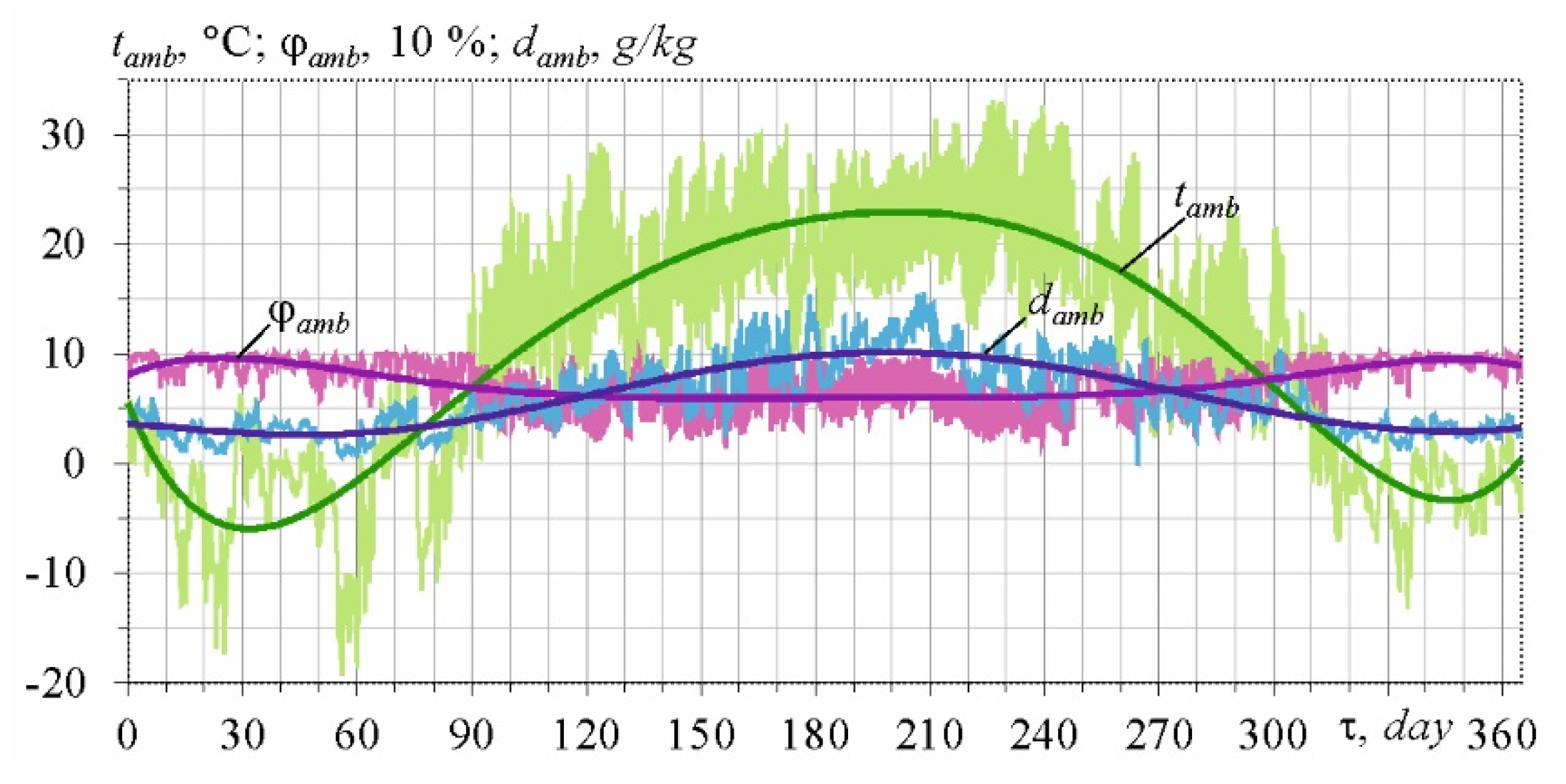
The GT operation climatic conditions are characterized by large fluctuations of ambient air parameters: temperature tamb, relative and absolute damb humidity (Figure 1).
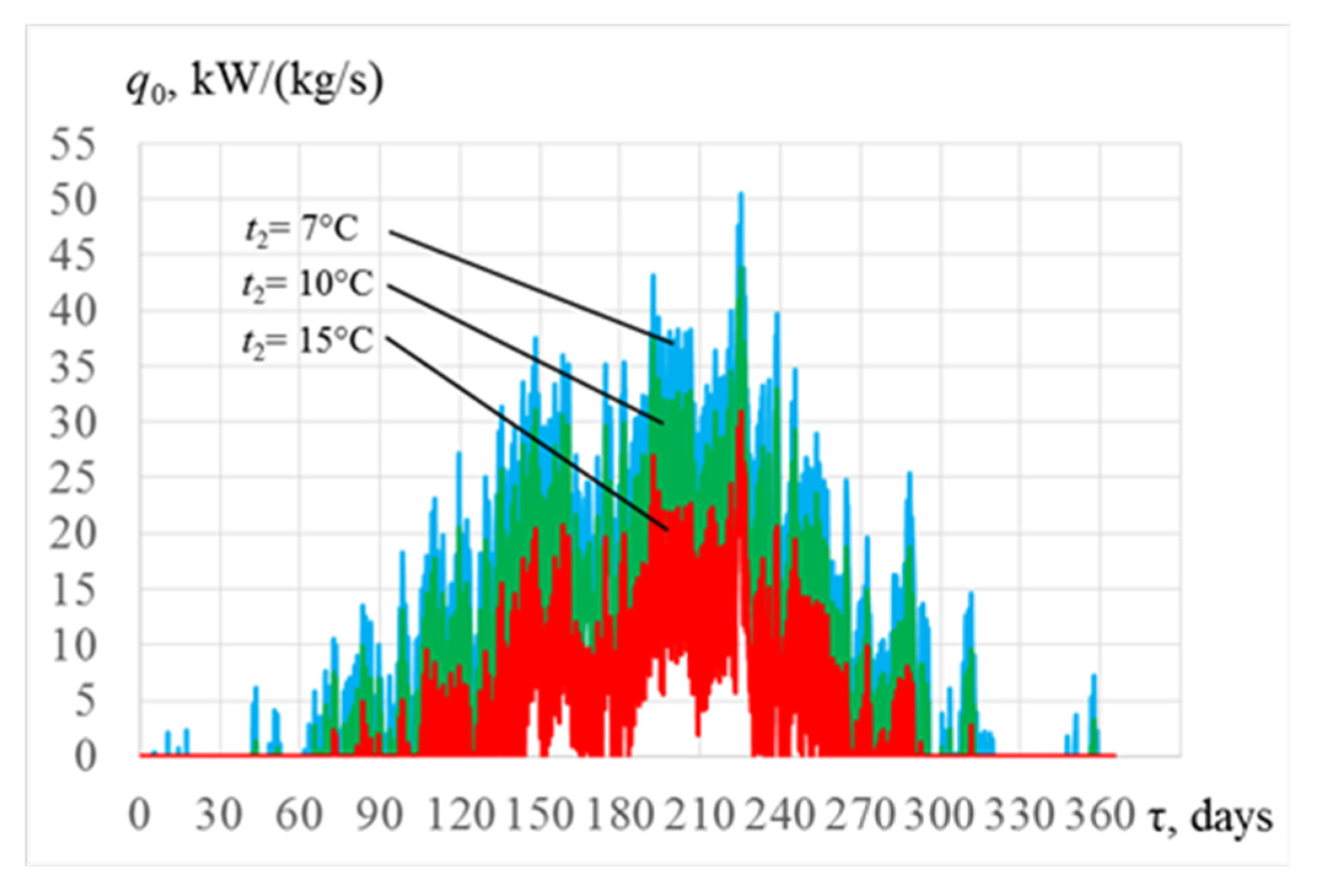
The fluctuation of ambient air parameters causes large changes of specific cooling capacities q0 required for cooling ambient air of unit air mass flow rate, Ga = 1 kg/s, at the intake of GT (changes in current specific thermal loads on cooling system) accordingly (Figure 2).
Such large yearly variations of specific cooling capacities q0.7, q0.10 and q0.15, required for cooling ambient air from current air temperatures ta to target temperatures of cooled air ta2 = 7, 10, and 15 °C reveal the actual problem to choose a design cooling capacity of the chillers and rational chiller compound of TIAC system to cover actual cooling duties without its oversizing and provide close to maximum annual fuel reduction.
Traditionally a turbine intake air is cooled to the temperature ta2 = 15 °C by a chilled water with a temperature of 7 °C from absorption lithium-bromide chiller (ACh) of a simple cycle with a high coefficient of performance COP from 0.7 to 0.8 (Figure 3).
As mentioned above, the lowest temperature of air cooled in ACh of a simple cycle is about 15 °C and limited by the temperature of chilled water of 7 °C at the inlet of air cooler.
To provide turbine intake air cooling to lower temperature of about 10 °C with corresponding increment of fuel saving the refrigerant with lower boiling point can be used as a coolant in the inlet air cooler and the ECh applied as the most simple in design and cheap, but not so high efficient as ACh: its COP is 0.2 to 0.3 versus COP of 0.7 for ACh.
So as the COP of ECh falls with lowering the boiling temperature of refrigerant, in order to keep the COP at the level of about 0.3 the refrigerant boiling temperature is to be about t0 from 4 to 5 °C and a thermal load on ECh should be restricted by its range, referred to subcooling the air, previously precooled in high efficient ACh.
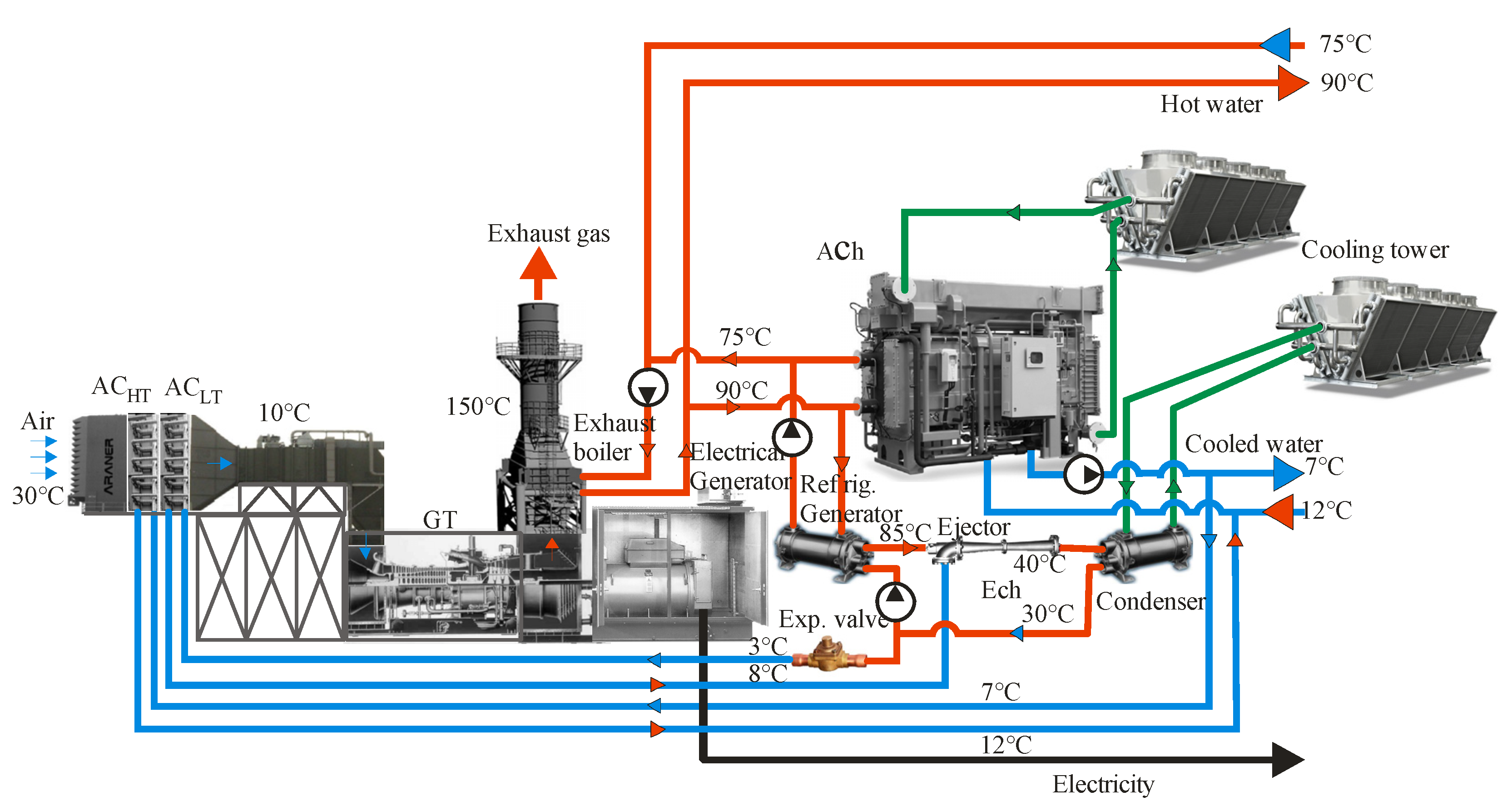
Issuing from this approach, a novel two-stage TIAC system has been proposed (Figure 4). Apparently it is reasonable to cool intake air from current ambient air temperature tamb to ta2 = 15 °C in ACh with high coefficient of performance COP from 0.7 to 0.8, but further deep cooling air from ta2 = 15 °C down to ta2 = 10 °C is possible by boiling refrigerant from ECh, i.e., in combined two-stage absorption-ejector chiller (AECh) (Figure 4). The use of ECh as a second stage of TIAC with previous ambient air precooling is caused by its low coefficient of performance COP from 0.2 to 0.3 that requires enlarged values of heat generated in exhaust boiler in the form of hot water or steam.
Further enhancing the efficiency of TIAC systems and the effect, as turbine fuel saving for example, gained due to their application, especially in the case of their running in temperate climatic conditions, is still depended on lowering the intake air temperature, limited by temperature of coolant in the air cooler. In the case of ECh, as low-temperature stage of two-stage AECH (SAECh), a decrease in refrigerant boiling temperature to t0 of 2 to 3 °C is accompanied by dropping its COP to 0.2 and lower. To compensate for a negative effect of decreasing a refrigerant boiling temperature t0 in ejector thermodynamic cycle, the refrigerant condensing temperature tc should be decreased too. This might be realized through cooling the condenser of ECh by chilled water from ACh with temperature of about 7 °C or by returned chilled water leaving the intake air cooler (high-temperature stage ACHT of hybrid intake air cooler) with temperature of about 10 to 12 °C. The last variant is more efficient due to the use of chilled water of enlarged flow rate in intake air cooler that is accompanied by decreasing its temperature arise and leads to increasing a heat flux in air cooler and reducing its dimensions as a result.
The reserves for the use of cooling capacity of ACh for enhancing the efficiency of ACh are proceeded from the variation of current thermal loads on TIAC system. At lowered ambient air temperatures, and thermal load on TIAC system accordingly, the excessive cooling capacity of ACh can be used for cooling the condenser of ECh to provide deeper air cooling to 7 °C and lower due to lowered refrigerant boiling temperature t0 of 2 to 3 °C as compared with two-stage cooling air to the temperature of 10 °C (at t0 of 4 to 5 °C) in a stage absorption-ejector chiller (SAECh).
In this case, the ECh operates as the low cascade of cascade absorption-ejector chiller (CAECh) to provide deeper cooling the intake air (to 7 °C and lower) previously precooled to the temperature of 15 °C in the first high-temperature stage of air cooler by ACh (Figure 5).
Such functioning of ECh as the low-temperature stage in SAECh to provide intake air cooling to 10 °C at increased ambient air temperatures and as low cascade of CAECh to provide deeper intake air cooling to 7 °C and lower at decreased ambient air temperature enables matching daily and seasonal fluctuations in thermal loads and efficient operation of TIAC systems in actual site climatic conditions.
In this case, we deal with universal combined stage-cascade absorption-ejector chiller (SCAECh), functioning as SAECh at increased ambient air temperatures and as SCAECh at its decreased temperatures or even as CAECh at ambient air temperatures close to 15 °C and lower. Such SCAECh provides a maximum effect, gained due to deep TIAC and matching daily and seasonal fluctuations in thermal loads, especially in temperate climatic conditions.
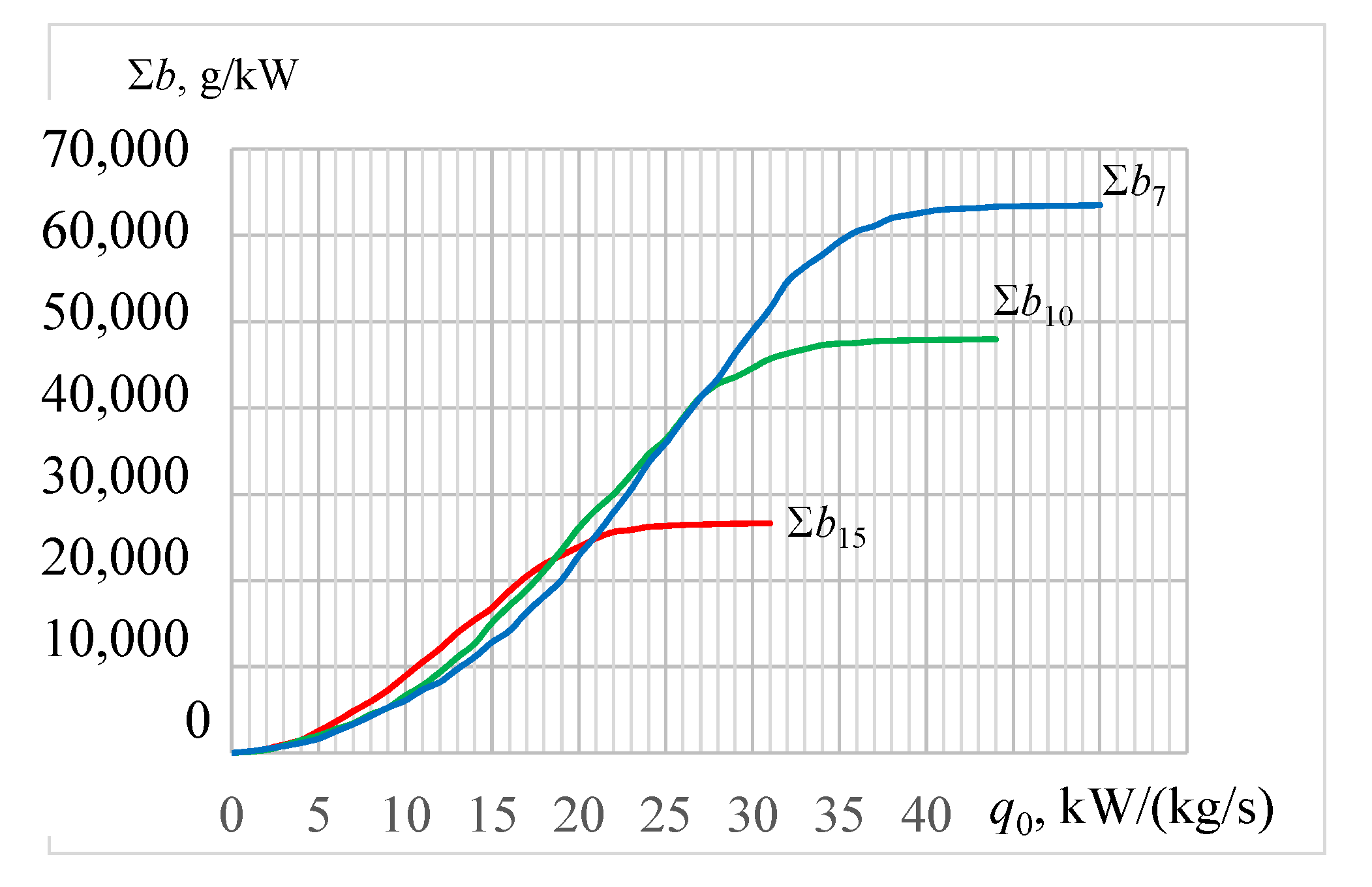
To determine a rational design thermal load on TIAC system that provides close to maximum annual values of fuel reduction the characteristic curves of annual values of CDH versus specific cooling capacity q0 (per unit air mass flow rate Ga = 1 kg/s) and total fuel reduction ∑B versus overall cooling capacity Q0 (per total air mass flow rate Ga) to target temperatures of cooled air ta2: 7 and 10 °C—in AECh; 15 °C—in ACh for climatic conditions in Mykolayiv region (southen Ukraine) are calculated as the first, traditional, stage of TIAC system designing (Figure 6).
The calculations are carried out for GT of rated power output NeISO = 10 MW and with account to assumption that a reduction of air temperature Δta by 1K leads to a decrease in specific fuel consumption Δbe by 1.0 g/(kWh), as it was assumed for easy calculation of fuel reduction ∑B and ∑b for another value of Δbe/Δta.
As it was mentioned above, in order to simplify calculations and to apply their results for any total cooling capacity Q0 and GT power output, it is convenient to carry out the calculations and present their results in relative (specific) value per unit air mass flow rate (Ga = 1 kg/s)—in the form of specific cooling capacity: q0 = Q0/Ga, kW/(kg/s), or kJ/kg, as well as annual fuel reduction in specific (relative) values ∑b for 1 kW power output of GT.
The annual values of GT specific fuel reduction ∑Δb (for 1 kW of GT power) due to intake air cooling from ambient air temperatures tamb to ta2 = 7, 10 and 15 °C by chillers with various specific cooling capacities q0 (per unit air mass flow rate Ga = 1 kg/s) for climatic conditions in Mykolayiv region (southen Ukraine) are presented in Figure 7.
Figure 6 and Figure 7 show that intake air cooling in AECh to ta2 = 10 °C provides more than 50% greater annual reduction in fuel consumption compared to cooling air to ta2 = 15 °C in ACh. As Figure 7 shows, a specific cooling capacity q0.10 is 33 to 35 kW/(kg/s), or kJ/kg, provide cooling ambient air from the current temperatures ta to ta2 = 10 °C with annual specific fuel reduction ∑b10 of 47 to 48 kg/kW (Figure 7) with corresponding overall cooling capacity Q0.10 of 1300 to 1400 kW providing a total fuel reduction ∑B10 of 470 to 480 t (Figure 6) that is close to their maximum value at noticeable high rate of their annual increment. While beyond the values Q0.10 of 1300 to 1400 kW or q0.10 of 33 to 35 kW/(kg/s) a rate of annual fuel reduction increment ∑B or ∑b is negligible, the range of corresponding cooling capacities Q0 or q0 needed is wide that approves a considerable chiller oversizing. Thus, the precise values of design cooling capacities Q0 or q0 are to be determined for appropriately sized TIAC system.
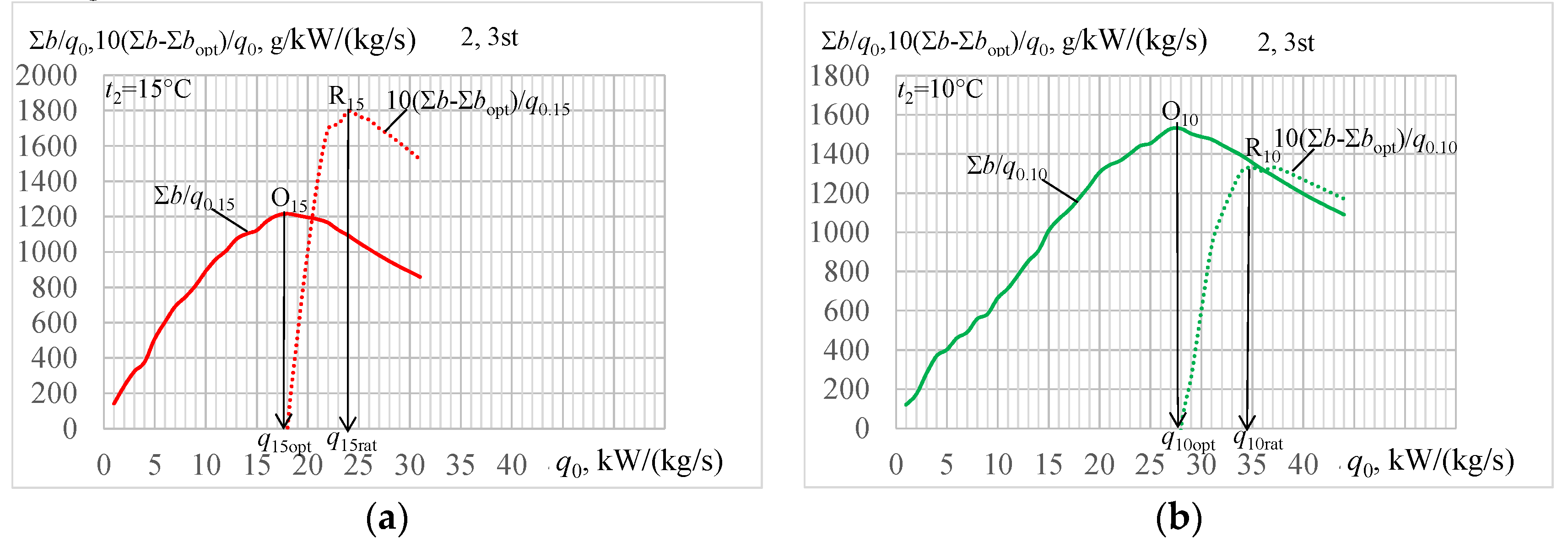
Furthermore, with arising a target temperature of cooled air ta2 to 15 °C it is more problematic to select precise value of rational design cooling capacity Q0.15rat or q0.15rat so as behavior of the curve ∑B = f(Q0) or ∑b = f(q0) becomes moderate (Figure 6 and Figure 7). Therefore the original method of determining a design cooling capacity has been modified by adding the stages aimed for calculation of optimal design cooling capacity Q0.opt or q0.opt corresponding to a maximum rate of annual fuel reduction increment ∑B/Q0∙or ∑b/q0 as intermediate stage (Figure 8) for determining the precise value of rational design specific cooling capacity q0.rat (Figure 9, Figure 10 and Figure 11).
The points O15 and O10 on the TIAC cumulative characteristics of dependence of annual specific fuel reduction ∑b15 and ∑b10 on the specific cooling capacities q0.15 and q0.10 are determined according to optimal values of design specific cooling capacities q0.15opt and q0.10opt, corresponding to maximum values of ratios ∑B/Q0∙or ∑b/q0, i.e., maximum rate of annual fuel reduction increment.
As Figure 8 shows, a maximum rate of annual specific fuel reduction increment ∑b/q0.15 due to cooling air to ta2 = 15 °C takes place at the optimal design specific cooling capacity q0.15opt = 16 kW/(kg/s) and provides the annual specific fuel reduction ∑b15opt = 22.5 kg/kW considerably less than its maximum value ∑b15max = 27 kg/kW. With cooling air targeting ta2 = 10 °C the optimal specific cooling capacity q0.10opt = 27 kW/(kg/s) provides ∑b10opt = 42 kg/kW less versus ∑b10max = 49 kg/kW.
To achieve close to maximum annual specific fuel reduction ∑b15opt at more precise value of rational cooling capacity q0.rat without oversizing the chiller, it is proposed to determine the maximum rate of annual specific fuel reduction increment as (∑b − ∑bopt)/q0.15 in the range of ∑b15 beyond its value ∑b15opt = 22.5 kg/kW corresponding to optimal design capacity q0.15opt = 16 kW/(kg/s) for cooling air to ta2 = 15 °C as well as beyond ∑b10opt = 42 kg/kW corresponding to q0.10opt = 27 kW/(kg/s) for ta2 = 10 °C (Figure 9 and Figure 10).
Here: q0.opt—optimal, q0.rat—rational and q0.max—maximum values; points O15 and O10 correspond to q0.15opt and q0.10opt; R15 and R10—for q0.15rat and q0. 10rat; Δq0.15 = q0.15max − q0.15rat and Δq0.10 = q0.10max − q0.10rat − reduction of design specific cooling capacity q0.
As Figure 9 and Figure 10 show, a maximum rate of annual specific fuel reduction increment (∑b − ∑bopt)/q0.15 when cooling ambient air to ta2 = 15 °C takes place at specific cooling capacity q0.15rat = 24 kW/(kg/s) and provides annual specific fuel reduction ∑b15rat very close to its maximum value ∑b15max = 27 kg/kW, but achieved at a rational cooling capacity q0.15rat = 24 kW/(kg/s) that is less than its oversized maximum value q0.15max = 31 kW/(kg/s) by Δq0.15 = q0.15max − q0.15rat of about 7 kW/(kg/s), i.e., more than 20%. When cooling ambient air to ta2 = 10 °C a maximum value of (∑b − ∑bopt)/q0.10 takes place at the rational cooling capacity q0.10rat = 37 kW/(kg/s) and provides annual specific fuel reduction ∑b10rat = 47 kg/kW that is close to its maximum value ∑b10max = 48 kg/kW and achieved at a rational cooling capacity q0.10rat = 37 kW/(kg/s) less than its oversized maximum value q0.10max = 44 kW/(kg/s) by Δq0.10 = q0.10max − q0.10rat of about 9 kW/(kg/s), i.e., approximately 20% less. The points R15 and R10 on the TIAC cumulative characteristics of dependence of annual specific fuel reduction ∑b15 = f(q0) and ∑b10 = f(q0) on the specific cooling capacities q0.15 and q0.10 are determined according to rational values of design specific cooling capacities q0.15rat and q0.10rat, calculated at the stage 3 of design methodology. As it is seen, the values of rational annual specific fuel reduction ∑b15rat and ∑b10rat, determined proceeding from the points R15 and R10, are very close to their maximum values ∑b15max and ∑b10max.
Graphs in Figure 9 and Figure 10 allow users to match current cooling duties and provide minimum sizing system at maximum rate of annular cooling effect increment due to operation at optimal cooling capacity q0.10opt (Figure 9) or to peak cooling needs without oversizing due to running at rational cooling capacity q0.rat (Figure 10).
4. Discussion
To generalize the results of analysing the efficiency of engine intake air cooling in TIAC systems, using chillers of different types, the optimal and rational design thermal loads for cooling intake air to target temperatures 7 to 15 °C in actual site climatic conditions were calculated step-by-step year round on the basis of the proposed novel methodology (Figure 11, Figure 12, Figure 13 and Figure 14).
As Figure 11 shows, a maximum rate of annual specific fuel reduction ∑b/q0 due to cooling ambient air to the temperatures ta2 = 7, 10 and 15 °C takes place at the optimal design specific cooling capacities (points O7, O10, O15): q0.7opt = 33 kW/(kg/s), q0.10opt = 27 kW/(kg/s) and q0.15opt = 16 kW/(kg/s), which provide annual specific fuel reduction ∑b7opt = 56 kg/kW, ∑b10opt = 42 kg/kW and ∑b15opt = 22 kg/kW considerably less than their maximum values. These values of ∑bopt are used to determine the range of annual specific fuel reduction (∑b − ∑bopt) beyond their optimal values ∑bopt to calculate the ratios (∑b − ∑bopt)/q0 that characterize the rate of annual specific fuel reduction beyond the optimal values ∑bopt and their maximum values correspond to rational design specific cooling capacities: q0.rat.
As Figure 11 and Figure 12 show, a maximum rate of annual fuel reduction increment (∑b − ∑bopt)/q0 in the ranges beyond their optimal values ∑bopt (Figure 11) is characterized by maximum values of ratios (∑b − ∑bopt)/q0 which correspond to rational design specific cooling capacities q0.rat when cooling ambient air to the temperatures ta2 = 7, 10 and 15 °C: q0.7rat = 41 kW/(kg/s), q0.10rat = 35 kW/(kg/s) and q0.15rat = 24 kW/(kg/s) (stage 3, Figure 12). These values of rational design specific cooling capacities q0.rat determine the position of the points R7, R10 and R15 on the TIAC cumulative characteristics of dependence of annual specific fuel reduction ∑b7 = f(q0), ∑b10 = f(q0) and ∑b15 = f(q0) and corresponding rational annual specific fuel reduction ∑b7rat, ∑b10rat and ∑b15rat, calculated at the stage 4 of design methodology (Figure 13).
As it is seen, the values of rational annual specific fuel reduction ∑b7rat, ∑b10rat and ∑b15rat, determined proceeding from the points R7, R10 and R15, are very close to their maximum values.
As Figure 13 shows, a maximum rate of annual specific fuel reduction increment (∑b − ∑bopt)/q0.15 when cooling ambient air to ta2 = 15 °C takes place at specific cooling capacity q0.15rat = 24 kW/(kg/s) and provides annual specific fuel reduction ∑b15rat very close to its maximum value ∑b15max = 26 kg/kW, but achieved at a rational cooling capacity q0.15rat less than its oversized maximum value q0.15max = 31 kW/(kg/s) by Δq0.15 = q0.15max − q0.15rat of about 7 kW/(kg/s), i.e., more than 20%. When cooling ambient air to ta2 = 10 °C a maximum value of (∑b–∑bopt)/q0.10 takes place at the rational cooling capacity q0.10rat = 35 kW/(kg/s) and provides annual specific fuel reduction ∑b10rat = 47 kg/kW that is close to its maximum value ∑b10max = 49 kg/kW and achieved at a rational cooling capacity q0.10rat less than its oversized maximum value q0.10max = 44 kW/(kg/s) by Δq0.10 = q0.10max − q0.10rat of about 9 kW/(kg/s), i.e., approximately 20% less.
The values of rational annual specific fuel reduction ∑b7rat, ∑b10rat and ∑b15rat, proceeding from the points R7, R10 and R15, determined according to rational cooling capacities q0.rat, are very close to their maximum values, but achieved at rational cooling capacities q0.rat less than their oversized maximum values by about 20% (Figure 14).
To generalize the results of analysing the efficiency of engine intake air cooling in TIAC systems by chillers of different types the TIAC cumulative characteristics of dependence of annual specific fuel reduction ∑b = f(q0) on the specific cooling capacities q0 are presented in relative values as referred to their maximum values, selected on the basis of traditional methods of designing, i.e., as ∑b/bmax = f(q0/q0.max) (Figure 15).
As shown in Figure 15, the application of developed novel methodology allows to determine the precise values of rational design specific cooling capacities q0.rat (corresponding overall values Q0.rat) of TIAC systems that provide annual fuel reduction very close to their maximum values, but achieved at cooling capacities less than the values, defined by traditional methods issuing from maximum yearly thermal loads or maximum annual effect due to intake air cooling, by about 20%.
As well as the proposed absorption-ejector TIAC systems, there are the advanced versions of typical basic absorption TIAC system, the economic comparison, where the latter might be done by taking into account only the cost of extra heat exchangers of ECh (refrigerant evaporator-air cooler, refrigerant condenser and ejector) with unchanged maintenance cost, personal costs, etc.
As a basic variant, the GT of power output of 10 MW and air mass flow rate Ga = 40 kg/s might be accepted for easy recalculation for turbines with other characteristics. According to Figure 14 q0.10rat = 35 kW/(kg/s) for TIAC system with AECh and q0.15rat = 24 kW/(kg/s) for traditional ACh or their total values Q0.10rat = 1400 kW and Q0.15rat = 960 kW for air mass flow rate Ga = 40 kg/s with corresponding annual specific fuel reduction ∑b10rat = 47 kg/kW and ∑b15rat = 26 kg/kW or annual total fuel reduction ∑B10rat = 470 t and ∑B15rat = 260 t. Proceeding from these data, the value of the total cooling load on low temperature ECh Q0.10-15rat= Q0.10rat − Q0.10rat i.e., 440 kW, provides additional annual fuel reduction ∑B10-15rat =∑B10rat − ∑B15rat about 210 t as compared with traditional TIAC system with ACh. Thus, the cooling capacity of refrigerant evaporator-air cooler of ECh Q0.10-15rat= 440 kW and of refrigerant condenser Qcondenser = Q0.10-15rat (1 + COP), i.e., about 1760 kW, where COP of ECh can be accepted as 0.3 [42,43]. Taking into account the cost of extra heat exchangers of ECh about 150,000$ according to [75] and including addition 10% increase for ejector and 10% for their mounting the cost of addition equipment of ECh is about 180,000$. On the other hand, the cost of gas fuel annually saved is about $45,000 (proceeding from the price of gas $150 per 1000 m3) and the payback period is about four years.
Because of the fluctuations in cost of heat exchangers of different manufacturers and the price of the gas fuel especially the economic analysis is to be conducted for the concrete case. Thus, we use the considered method of designing focuses to provide just initial basic data as rational technical characteristics for further complicated detailed economic analysis.
The proposed approach and a novel methodology of rational designing of engine intake air cooling systems enables saving about 20% of financial expenses and to cover actual yearly cooling duties without cooling system oversizing and unproductive decrease of engine power output to overcome the intake air pressure drop in oversized air coolers.
Such a method is quite quantitative to evaluate the effect due to cooling and select the rational design cooling capacity and estimate a decrease in sizes of chillers.
5. Conclusions
The efficiency of cooling ambient air at the inlet of gas turbines in temperate climatic conditions by waste heat recovery chillers, using the exhaust gas heat, was analyzed and reserves for its enhancing through deep cooling were revealed.
The gas turbine intake air cooling by combined absorption-ejector chillers (AECh) with ACh as a high temperature cooling stage and ECh as a low temperature cooling stage was proposed. It was shown that turbine intake air cooling to about 7 to 10 °C in temperate climatic conditions by combined absorption-ejector chillers provides an annual fuel saving of about 50% greater than its value gained due to traditional air cooling to about 15 °C in absorption lithium-bromide chiller of a simple cycle.
As a result, a novel trend in engine intake air cooling in temperate climatic conditions by two-stage cooling in chillers of combined type has been proposed.
A method of logical analysis of the actual operation efficiency of turbine intake air cooling systems in site varying environment, supplemented by the simplest numerical simulation, was used to synthesize new solutions. The real input data on site actual climatic conditions (ambient air temperature tamb and relative humidity ) were taken by using the well-known program “meteomanz” [74].
The annual fuel reduction was considered to be a primary criterion as an example.
The novelty of the research methodological approach to analysis of the TIAC system operation efficiency consists of summation of the current changeable effect (fuel reduction) due to cooling air over the year as an annular effect (annual fuel saving). The rate of its increment according to cooling capacity is used as an indicator to efficient realization of the design cooling capacity.
The improved methodology of TIAC system designing, based on this methodological approach, is developed. It involves the stages to determine an optimal value of cooling capacity, providing the minimum system sizes at maximum rate of annual effect increment, and its rational value, providing a close to maximum annual effect without TIAC system oversizing at the second maximum rate of annual effect increment within the range beyond the first maximum rate.
Such a method is quite quantitative when evaluating the effect due to cooling, selecting design cooling capacity, and estimating a decrease in sizes of chillers.
The rational value of design cooling capacity (thermal load) provides practically maximum annual fuel saving but with reduced by about 15 to 20% sizes of cooling systems due to correspondingly reduced design cooling capacity of the systems as compared with their values defined by traditional designing focused to cover maximum current thermal loads.
The method allows users to peak maximum cooling needs without oversizing system or provide minimum sizing TIAC system at maximum rate of annular cooling effect. The last variant of TIAC system operation is very reasonable for applying the energy saving technologies, for instance, based on the thermal storage with accumulating excessive (not consumed) cooling capacities at lowered current thermal loads on the cooling system to cover the peak loads.
Author Contributions
Conceptualization, A.R. (40%), M.R. (30%), E.T. (10%), K.K. (10%) and D.M. (10%); methodology, A.R. (30%), E.T. (30%) and M.R. (30%).; software, A.R.; validation, A.R. (30%). and M.R. (30%); formal analysis, A.R. (30%), E.T. (30%), K.K. (30%), D.M. (30%) and M.R.; writing—original draft preparation, A.R. (30%), E.T. (30%) and M.R. (30%); writing—review and editing, D.M. (50%) and K.K. (50%). All authors have read and agreed to the published version of the manuscript.
Funding
This research received no external funding.
Conflicts of Interest
The authors declare no conflict of interest.
Nomenclature
| AC | air cooler |
| ACHT | high-temperature air cooler |
| ACLT | low-temperature air cooler |
| ACh | absorption lithium-bromide chiller |
| AECh | absorption-ejector chiller |
| CAECh | cascade absorption-ejector chiller |
| CDH | cooling degree hour; CDH = Δt·τ |
| COP | coefficient of performance |
| ECh | ejector chiller |
| GT | gas turbine |
| O | optimal point for maximum rate of annual fuel reduction increment |
| R | rational point for close to maximum annual fuel reduction |
| SAECh | stage absorption-ejector chiller |
| SCAECh | stage-cascade absorption-ejector chiller |
| TIAC | turbine intake air cooling |
| Symbols | |
| B | total mass fuel consumption decrease, B = CDH (Δbe/Δt)∙Pe. |
| be | specific fuel consumption |
| ca | specific heat of humid air |
| CDH | CDH = Δt·τ |
| damb | ambient air absolute humidity |
| Ga | air mass flow rate |
| Pe | power output |
| Q0 | total cooling capacity, heat flow rate |
| q0 | specific cooling capacity—per unit air mass flow rate |
| t | temperature |
| tamb | ambient air temperature |
| ta2 | outlet air temperature |
| t0 | refrigerant boiling temperature |
| ξ | specific heat ratio of the total heat (latent and sensible) rejected from air to its sensible heat |
| τ | time interval |
| φamb | ambient air relative humidity |
| Δbe | specific fuel consumption decrease |
| Δt | air temperature decrease |
| ∑B7,10,15 | annual total fuel reduction due to cooling turbine intake air to temperatures 7, 10, 15 °C |
| ∑b7,10,15 | annual specific fuel reduction (per 1 kW turbine power output) due to cooling turbine intake air to temperatures 7, 10, 15 °C |
| Subscripts | |
| a | air |
| amb | ambient |
| max | maximum |
| opt | optimal |
| rat | rational |
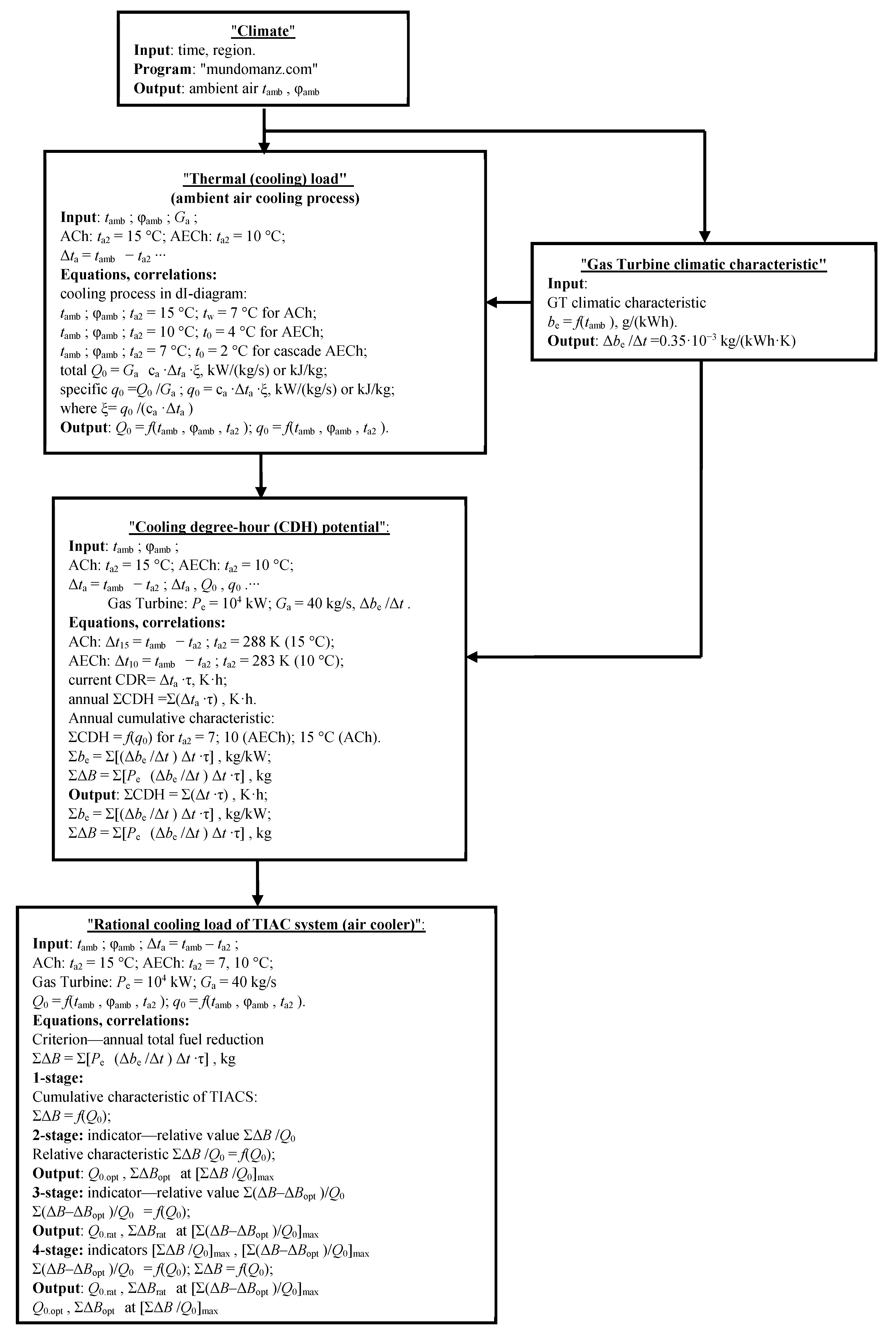
Appendix A
Figure A1.
Flow chart of calculation procedure.
References
- Tiwari, A.K.; Hasan, M.M.; Islam, M. Effect of Ambient Temperature on the Performance of a Combined Cycle Power Plant. Trans. Can. Soc. Mech. Eng. 2013, 37, 1177–1188. [Google Scholar] [CrossRef] [Green Version]
- Günnur, Ş.; Mustafa, N.; Hayati, M.; Halit, D.; Mustafa, K.; Mevlüt, K.; Fadıl, K.; Nuran, Y.; Mohammad, R.A.B. The effect of ambient temperature on electric power generation in natural gas combined cycle power plant—A case study. Energy Rep. 2018, 4, 682–690. [Google Scholar]
- Lin, A.; Sun, Y.; Zhang, H.; Lin, X.; Yang, L.; Zheng, Q. Fluctuating characteristics of air-mist mixture flow with conjugate wall-film motion in a compressor of gas turbine. Appl. Therm. Eng. 2018, 142, 779–792. [Google Scholar] [CrossRef]
- ISO 3046-1:2002. Reciprocating Internal Combustion Engines—Performance—Part 1: Declarations of Power, Fuel and Lubricating Oil Consumptions, and Test Methods—Additional Requirements for Engines for General Use; ISO: Geneva, Switzerland, 2014; Available online: https://www.iso.org/standard/28330.html (accessed on 14 June 2020).
- Payrhuber, K.; Trapp, C. GE’s New Jenbacher Gas Engines with 2-Stage Turbocharging. In Proceedings of the 7 Internationale Energiewirtschaftstagung an der TU Wien IEWT, Wien, Austria, 16–18 February 2011. 14p. [Google Scholar]
- Trapp, C.; Laiminger, S.; Chvatal, D.; Wimmer, A.; Schneßl, E.; Pirker, G. Die neue Gasmotorengeneration von GE Jenbacher—Mit zweistufiger Aufladung zu höchsten Wirkungsgraden. In Proceedings of the 32nd Internationales Wiener Motorensymposium, Wien, Austria, 5–6 May 2011. [Google Scholar]
- Radchenko, A.; Mikielewicz, D.; Forduy, S.; Radchenko, M.; Zubarev, A. Monitoring the Fuel Efficiency of Gas Engine in Integrated Energy System. In Proceedings of the Advances in Intelligent Systems and Computing, Kharkiv, Ukraine, 28–30 November 2019; Volume 1113, pp. 361–370. [Google Scholar]
- Farouk, N.; Sheng, L.; Hayat, Q. Effect of Ambient Temperature on the Performance of Gas Turbines Power Plant. Int. J. Comput. Sci. 2013, 10, 439–442. [Google Scholar]
- Baakeem, S.S.; Orfi, J.; Al Ansary, H. Performance of a Typical Simple Gas Turbine Unit under Saudi Weather Conditions. Int. J. Fluid Mechan. Therm. Sci. 2015, 1, 59–71. [Google Scholar]
- De Sa, A.; Al Zubaidy, S. Gas turbine performance at varying ambient temperature. Appl. Therm. Eng. 2011, 31, 2735–2739. [Google Scholar] [CrossRef]
- Shukla, A.K.; Singh, O. Thermodynamic investigation of parameters affecting the execution of steam injected cooled gas turbine based combined cycle power plant with vapor absorption inlet air cooling. Appl. Therm. Eng. 2017, 122, 380–388. [Google Scholar] [CrossRef]
- Al-Ibrahim, A.M.; Varnham, A. A review of inlet air-cooling technologies for enhancing the performance of combustion turbines in Saudi Arabia. Appl. Therm. Eng. 2010, 30, 1879–1888. [Google Scholar] [CrossRef]
- Zhang, T.; Liu, Z.; Hao, H.; Chang, L. Application Research of Intake-Air Cooling Technologies in Gas-Steam Combined Cycle Power Plants in China. J. Power Energy Eng. 2014, 2, 304–311. [Google Scholar] [CrossRef]
- Chaker, M.; Meher-Homji, C.B. Inlet Fogging of Gas Turbine Engines: Climatic Analysis of Gas Turbine Evaporative Cooling Potential of International Locations. J. Eng. Gas Turbines Power 2006, 128, 815–825. [Google Scholar] [CrossRef]
- Saghafifar, M.; Gadalla, M. Analysis of Maisotsenko open gas turbine power cycle with a detailed air saturator model. Appl. Energy 2015, 149, 338–353. [Google Scholar] [CrossRef]
- Dizaji, H.S.; Hu, E.J.; Chen, L.; Pourhedayat, S. Using novel integrated Maisotsenko cooler and absorption chiller for cooling of gas turbine inlet air. Energy Convers. Manag. 2019, 195, 1067–1078. [Google Scholar] [CrossRef]
- Rocha, M.; Andreos, R.; Simões-Moreira, J.R. Performance tests of two small trigeneration pilot plants. Appl. Therm. Eng. 2012, 41, 84–91. [Google Scholar] [CrossRef]
- Freschi, F.; Giaccone, L.; Lazzeroni, P.; Repetto, M. Economic and environmental analysis of a trigeneration system for food-industry: A case study. Appl. Energy 2013, 107, 157–172. [Google Scholar] [CrossRef]
- Marques, R.P.; Hacon, D.; Tessarollo, A.; Parise, J.A.R. Thermodynamic analysis of tri-generation systems taking into account refrigeration, heating and electricity load demands. Energy Build. 2010, 42, 2323–2330. [Google Scholar] [CrossRef]
- Ortiga, J.; Bruno, J.C.; Coronas, A. Operational optimization of a complex trigeneration system connected to a district heating and cooling network. Appl. Therm. Eng. 2013, 50, 1536–1542. [Google Scholar] [CrossRef]
- Dr. Fromme International Consulting. Cogeneration & Trigeneration—How to Produce Energy Efficiently: A Practical Guide for Experts in Emerging and Developing Economies, GIZ GmbH, Germany; Dr. Fromme International Consulting: Essen, Germany, 2016; 144p, Available online: https://www.dfic.de/images/pdf/cogeneration-trigeneration-guide.pdf (accessed on 14 June 2020).
- Muszyński, T.; Mikielewicz, D. Comparison of heat transfer characteristics in surface cooling with boiling microjets of water, ethanol and HFE7100. Appl. Therm. Eng. 2016, 93, 1403–1409. [Google Scholar] [CrossRef] [Green Version]
- Chacartegui, R.; Jiménez-Espadafor, F.; Sánchez, D.; Sánchez, T. Analysis of combustion turbine inlet air cooling systems applied to an operating cogeneration power plant. Energy Convers. Manag. 2008, 49, 2130–2141. [Google Scholar] [CrossRef]
- Khaliq, A.; Dincer, I.; Sharma, P.B. Development and analysis of industrial waste heat based trigeneration for combined production of power heat and cold. J. Energy Inst. 2010, 83, 79–85. [Google Scholar] [CrossRef]
- Popli, S.; Rodgers, P.; Eveloy, V. Trigeneration scheme for energy efficiency enhancement in a natural gas processing plant through turbine exhaust gas waste heat utilization. Appl. Energy 2012, 93, 624–636. [Google Scholar] [CrossRef]
- Popli, S.; Rodgers, P.; Eveloy, V. Gas turbine efficiency enhancement using waste heat powered absorption chillers in the oil and gas industry. Appl. Therm. Eng. 2013, 50, 918–931. [Google Scholar] [CrossRef]
- Ameri, M.; Hejazi, S. The study of capacity enhancement of the Chabahar gas turbine installation using an absorption chiller. Appl. Therm. Eng. 2004, 24, 59–68. [Google Scholar] [CrossRef]
- Ehyaei, M.A.; Hakimzadeh, S.; Enadi, N.; Ahmadi, P. Exergy, economic and environment (3E) analysis of absorption chiller inlet air cooler used in gas turbine power plants. Int. J. Energy Res. 2011, 36, 486–498. [Google Scholar] [CrossRef]
- Andi, B.; Venkatesan, J.; Suresh, S.; Mariappan, V. Experimental Analysis of Triple Fluid Vapour Absorption Refrigeration System Driven by Electrical Energy and Engine Waste Heat. Therm. Sci. 2019, 23, 2995–3001. [Google Scholar]
- Elberry, M.; Elsayed, A.; Teamah, M.; Abdel-Rahman, A.; Elsafty, A. Performance improvement of power plants using absorption cooling system. Alex. Eng. J. 2018, 57, 2679–2686. [Google Scholar] [CrossRef]
- Umberto, L. Adsorber efficiency in adsorbtion refrigeration. Renew. Sustain. Energy Rev. 2013, 20, 570–575. [Google Scholar]
- Sur, A.; Das, R.; Sah, R. Influence of initial bed temperature on bed performance of an adsorption refrigeration system. Therm. Sci. 2018, 22, 2583–2595. [Google Scholar] [CrossRef]
- Suamir, I.; Tassou, S. Performance evaluation of integrated trigeneration and CO2 refrigeration systems. Appl. Therm. Eng. 2013, 50, 1487–1495. [Google Scholar] [CrossRef]
- Bohdal, T.; Kuczynski, W. Boiling of R404A Refrigeration Medium Under the Conditions of Periodically Generated Disturbances. Heat Transf. Eng. 2011, 32, 359–368. [Google Scholar] [CrossRef]
- Bohdal, T.; Sikora, M.; Widomska, K.; Radchenko, A.M. Investigation of flow structures during HFE-7100 refrigerant condensation. Arch. Thermodyn. 2015, 36, 25–34. [Google Scholar] [CrossRef] [Green Version]
- Kuczyński, W.; Charun, H. Experimental investigations into the impact of the void fraction on the condensation characteristics of R134a refrigerant in minichannels under conditions of periodic instability. Arch. Thermodyn. 2011, 32, 21–37. [Google Scholar] [CrossRef]
- Kuczyski, W.; Charun, H.; Bohdal, T.; Kuczynski, W. Influence of hydrodynamic instability on the heat transfer coefficient during condensation of R134a and R404A refrigerants in pipe mini-channels. Int. J. Heat Mass Transf. 2012, 55, 1083–1094. [Google Scholar] [CrossRef]
- Radchenko, M.; Mikielewicz, D.; Tkachenko, V.; Klugmann, M.; Andreev, A. Enhancement of the Operation Efficiency of the Transport Air Conditioning System. In Proceedings of the Lecture Notes in Mechanical Engineering, Kharkiv, Ukraine, 9–12 June 2020; pp. 332–342. [Google Scholar]
- Trushliakov, E.; Radchenko, M.; Bohdal, T.; Radchenko, R.; Kantor, S. An Innovative Air Conditioning System for Changeable Heat Loads. In Proceedings of the Lecture Notes in Mechanical Engineering, Odessa, Ukraine, 10–13 September 2019; pp. 616–625. [Google Scholar]
- Mikielewicz, D.; Wajs, J. Performance of the very high-temperature heat pump with low GWP working fluids. Energy 2020, 182, 460–470. [Google Scholar] [CrossRef]
- Forduy, S.; Radchenko, A.M.; Kuczynski, W.; Zubarev, A.; Konovalov, D. Enhancing the Gas Engines Fuel Efficiency in Integrated Energy System by Chilling Cyclic Air. In Proceedings of the Lecture Notes in Mechanical Engineering, Kharkiv, Ukraine, 9–12 June 2020; pp. 500–509. [Google Scholar]
- Butrymowicz, D.; Gagan, J.; Śmierciew, K.; Łukaszuk, M.; Dudar, A.; Pawluczuk, A.; Łapiński, A.; Kuryłowicz, A. Investigations of prototype ejection refrigeration system driven by low grade heat. E3S Web Conf. 2018, 70, 03002. [Google Scholar] [CrossRef]
- Elbel, S.; Lawrence, N. Review of recent developments in advanced ejector technology. Int. J. Refrig. 2016, 62, 1–18. [Google Scholar] [CrossRef]
- Lawrence, N.; Elbel, S. Experimental investigation of a two-phase ejector cycle suitable for use with low-pressure refrigerants R134a and R1234yf. Int. J. Refrig. 2014, 38, 310–322. [Google Scholar] [CrossRef]
- Radchenko, R.; Kornienko, V.; Pyrysunko, M.; Bogdanov, M.; Andreev, A. Enhancing the Efficiency of Marine Diesel Engine by Deep Waste Heat Recovery on the Base of Its Simulation Along the Route Line. In Proceedings of the Advances in Intelligent Systems and Computing, Kharkiv, Ukraine, 28–30 November 2019; Volume 1113, pp. 337–350. [Google Scholar]
- Kornienko, V.; Radchenko, M.; Radchenko, R.; Konovalov, D.; Andreev, A.; Pyrysunko, M. Improving the efficiency of heat recovery circuits of cogeneration plants with combustion of water-fuel emulsions. Therm. Sci. 2020, 154. [Google Scholar] [CrossRef] [Green Version]
- Konovalov, D.; Trushliakov, E.; Radchenko, M.; Kobalava, H.; Maksymov, V. Research of the Aerothermopressor Cooling System of Charge Air of a Marine Internal Combustion Engine Under Variable Climatic Conditions of Operation. In Proceedings of the Grabchenko’s International Conference on Advanced Manufacturing Processes, Odessa, Ukraine, 10–13 September 2019; pp. 520–529. [Google Scholar]
- Konovalov, D.; Kobalava, H.; Maksymov, V.; Radchenko, R.; Avdeev, M. Experimental Research of the Excessive Water Injection Effect on Resistances in the Flow Part of a Low-Flow Aerothermopressor. In Proceedings of the Advances in Design, Simulation and Manufacturing III, Kharkiv, Ukraine, 9–12 June 2020; pp. 292–301. [Google Scholar]
- Kornienko, V.; Radchenko, R.; Stachel, A.; Andreev, A.; Pyrysunko, M. Correlations for Pollution on Condensing Surfaces of Exhaust Gas Boilers with Water-Fuel Emulsion Combustion. In Proceedings of the Grabchenko’s International Conference on Advanced Manufacturing Processes, Odessa, Ukraine, 10–13 September 2019; pp. 530–539. [Google Scholar]
- Kornienko, V.; Radchenko, R.; Konovalov, D.; Andreev, A.; Pyrysunko, M. Characteristics of the Rotary Cup Atomizer Used as Afterburning Installation in Exhaust Gas Boiler Flue. In Proceedings of the Advances in Design, Simulation and Manufacturing III, Kharkiv, Ukraine, 9–12 June 2020; pp. 302–311. [Google Scholar]
- Trushliakov, E.; Radchenko, A.; Radchenko, M.; Kantor, S.; Zielikov, O. The Efficiency of Refrigeration Capacity Regulation in the Ambient Air Conditioning Systems. In Proceedings of the Advances in Design, Simulation and Manufacturing III, Kharkiv, Ukraine, 9–12 June 2020; pp. 343–353. [Google Scholar]
- Mikielewicz, D.; Kosowski, K.; Tucki, K.; Piwowarski, M.; Stępień, R.; Orynycz, O.; Włodarski, W. Gas Turbine Cycle with External Combustion Chamber for Prosumer and Distributed Energy Systems. Energies 2019, 12, 3501. [Google Scholar] [CrossRef] [Green Version]
- Wajs, J.; Mikielewicz, D.; Jakubowska, B. Performance of the domestic micro ORC equipped with the shell-and-tube condenser with minichannels. Energy 2018, 157, 853–861. [Google Scholar] [CrossRef]
- Leonzio, G. An innovative trigeneration system using biogas as renewable energy. Chin. J. Chem. Eng. 2018, 26, 1179–1191. [Google Scholar] [CrossRef]
- Maraver, D.; Sin, A.; Royo, J.; Sebastián, F. Assessment of CCHP systems based on biomass combustion for small-scale applications through a review of the technology and analysis of energy efficiency parameters. Appl. Energy 2013, 102, 1303–1313. [Google Scholar] [CrossRef]
- Cherednichenko, O.; Havrysh, V.; Shebanin, V.; Kalinichenko, A.; Mentel, G.; Nakonieczny, J. Local Green Power Supply Plants Based on Alcohol Regenerative Gas Turbines: Economic and Environmental Aspects. Energies 2020, 13, 2156. [Google Scholar] [CrossRef]
- Cherednichenko, O.; Mitienkova, V. Analysis of the Impact of Thermochemical Recuperation of Waste Heat on the Energy Efficiency of Gas Carriers. J. Mar. Sci. Appl. 2020, 19, 72–82. [Google Scholar] [CrossRef]
- Mikielewicz, D.; Wajs, J.; Andrzejczyk, R.; Klugmann, M. Pressure drop of HFE7000 and HFE7100 during flow condensation in minichannels. Int. J. Refrig. 2016, 68, 226–241. [Google Scholar] [CrossRef]
- Yang, C.; Yang, Z.; Cai, R. Analytical method for evaluation of gas turbine inlet air cooling in combined cycle power plant. Appl. Energy 2009, 86, 848–856. [Google Scholar] [CrossRef]
- Mahmoudi, S.; Zare, V.; Ranjbar, F.; Farshi, L.G. Energy and Exergy Analysis of Simple and Regenerative Gas Turbines Inlet Air Cooling Using Absorption Refrigeration. J. Appl. Sci. 2009, 9, 2399–2407. [Google Scholar] [CrossRef]
- Chaker, M.; Meher-Homji, C.B.; Mee, T.; Nicholson, A. Inlet Fogging of Gas Turbine Engines Detailed Climatic Analysis of Gas Turbine Evaporation Cooling Potential in the USA. J. Eng. Gas Turbines Power 2002, 125, 300–309. [Google Scholar] [CrossRef]
- Coskun, C.; Demiral, D.; Ertürk, M.; Oktay, Z. Modified Degree-Hour Calculation Method. Available online: http://www.intechopen.com/books/solar-power/modified-degree-hour-calculation-method (accessed on 10 June 2020).
- Forsyth, J.L. Gas turbine inlet air chilling for LNG. In Proceedings of the IGT International Liquefied Natural Gas Conference, Houston, TX, USA, 6–19 April 2013; Volume 3, pp. 1763–1778. Available online: https://www.scopus.com/record/display.uri?eid=2-s2.0-84904725071&origin=inward&txGid=b9d07662f250f4a4511cbfc9c242297a (accessed on 10 June 2020).
- Kalhori, S.B.; Rabiei, H.; Mansoori, Z. Mashad trigeneration potential—An opportunity for CO2 abatement in Iran. Energy Conv. Manag. 2012, 60, 106–114. [Google Scholar] [CrossRef]
- Canova, A.; Cavallero, C.; Freschi, F. Optimal energy management. IEEE Ind. Appl. Mag. 2009, 15, 62–65. [Google Scholar] [CrossRef]
- Rodriguez-Aumente, P.A.; Rodriguez-Hidalgo, M.D.C.; Nogueira, J.I.; Lecuona, A.; Venegas, M.D.C. District heating and cooling for business buildings in Madrid. Appl. Therm. Eng. 2013, 50, 1496–1503. [Google Scholar] [CrossRef]
- Kavvadias, K.; Maroulis, Z. Multi-objective optimization of a trigeneration plant. Energy Policy 2010, 38, 945–954. [Google Scholar] [CrossRef]
- Lozano, M.A.; Ramos, J.C.; Serra, L.M. Cost optimization of the design of CHCP (combined heat, cooling and power) systems under legal constraints. Energy 2010, 35, 794–805. [Google Scholar] [CrossRef]
- Radchenko, A.; Radchenko, M.; Trushliakov, E.; Kantor, S.; Tkachenko, V. Statistical Method to Define Rational Heat Loads on Railway Air Conditioning System for Changeable Climatic Conditions. In Proceedings of the 5th International Conference on Systems and Informatics (ICSAI), Nanjing, China, 10–12 November 2018; pp. 1294–1298. [Google Scholar]
- Radchenko, M.; Radchenko, R.; Tkachenko, V.; Kantor, S.; Smolyanoy, E. Increasing the Operation Efficiency of Railway Air Conditioning System on the Base of Its Simulation Along the Route Line. In Proceedings of the Advances in Intelligent Systems and Computing, Kharkiv, Ukraine, 28–30 November 2019; Volume 1113, pp. 461–467. [Google Scholar]
- Radchenko, A.; Bohdal, Ł.; Zongming, Y.; Portnoi, B.; Tkachenko, V. Rational Designing of Gas Turbine Inlet Air Cooling System. In Proceedings of the Grabchenko’s International Conference on Advanced Manufacturing Processes, Odessa, Ukraine, 10–13 September 2019; pp. 591–599. [Google Scholar]
- Reynolds, O., IV. On the dynamical theory of incompressible viscous fluids and the determination of the criterion. Philos. Trans. R. Soc. A Math. Phys. Eng. Sci. 1895, 186, 123–164. [Google Scholar] [CrossRef]
- Hewitt, G.; Govan, A. Phenomenological modelling of non-equilibrium flows with phase change. Int. J. Heat Mass Transf. 1990, 33, 229–242. [Google Scholar] [CrossRef]
- Available online: http://www.meteomanz.com (accessed on 12 June 2020).
- GPF Software. Available online: https://www.guentner.eu/know-how/product-calculator-gpc/gpc-software/ (accessed on 10 June 2020).
Figure 1.
Ambient air temperatures tamb, relative and absolute damb humidity in 2017, Mykolayiv region (southern Ukraine).
Figure 1.
Ambient air temperatures tamb, relative and absolute damb humidity in 2017, Mykolayiv region (southern Ukraine).

Figure 2.
Changes of specific cooling capacities q0.7, q0.10 and q0.15 required for cooling ambient air with unit mass flow rate of 1 kg/s from its actual temperature tamb to t2 = 7, 10 and 15 °C.
Figure 2.
Changes of specific cooling capacities q0.7, q0.10 and q0.15 required for cooling ambient air with unit mass flow rate of 1 kg/s from its actual temperature tamb to t2 = 7, 10 and 15 °C.

Figure 3.
A scheme of gas turbine intake air cooling system with absorption lithium-bromide chiller (ACh) using the heat of exhaust gas: AC—air cooler.
Figure 3.
A scheme of gas turbine intake air cooling system with absorption lithium-bromide chiller (ACh) using the heat of exhaust gas: AC—air cooler.
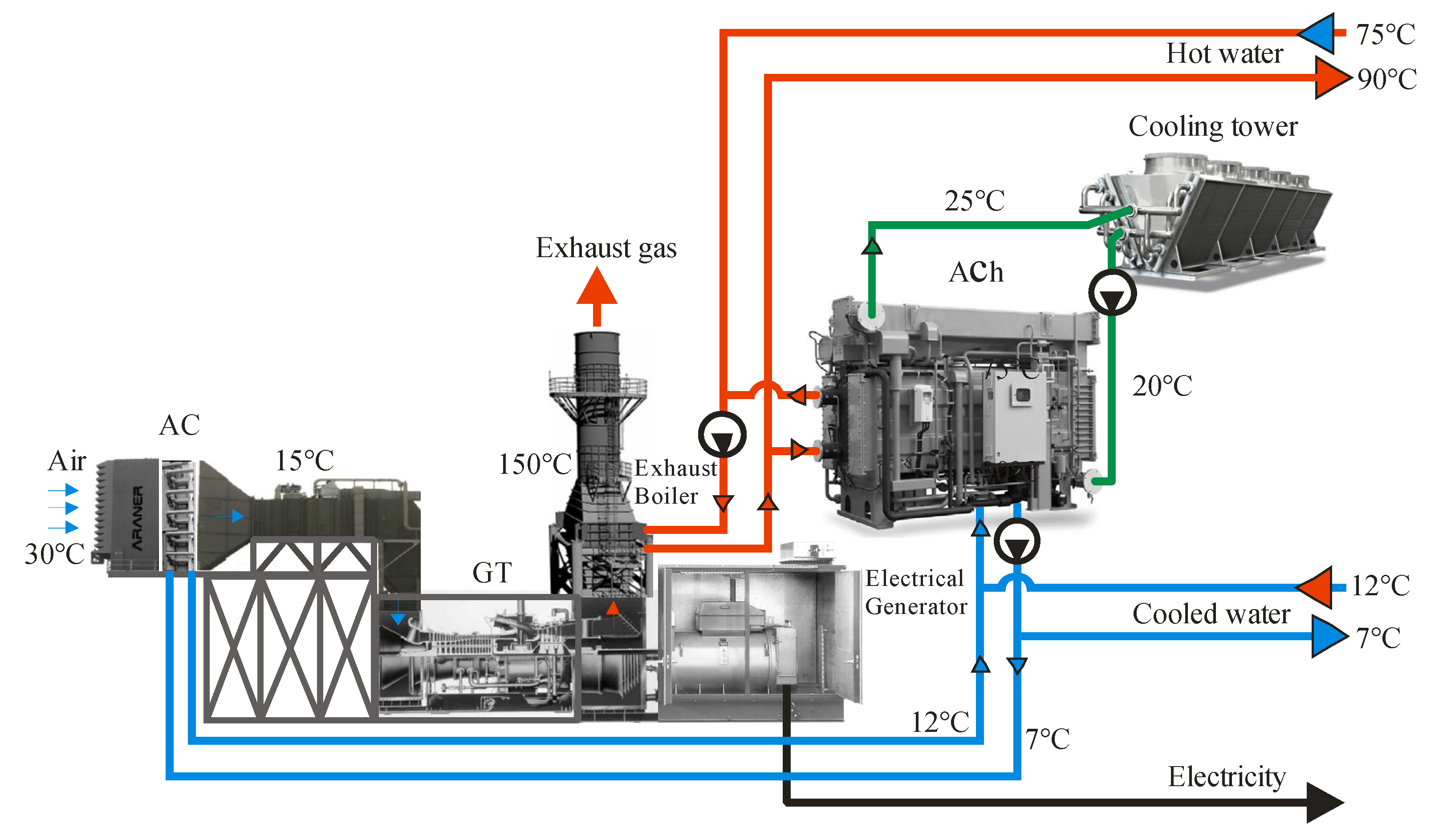
Figure 4.
A scheme of two-stage gas turbine intake air cooling system in stage absorption-ejector chiller (SAECh): ACHT—high-temperature stage of air cooler; ACLT—low-temperature stage of air cooler; Exp.Valve—expansion valve.
Figure 4.
A scheme of two-stage gas turbine intake air cooling system in stage absorption-ejector chiller (SAECh): ACHT—high-temperature stage of air cooler; ACLT—low-temperature stage of air cooler; Exp.Valve—expansion valve.

Figure 5.
A scheme of two-stage gas turbine intake air cooling system in stage cascade absorption-ejector chiller (SCAECh).
Figure 5.
A scheme of two-stage gas turbine intake air cooling system in stage cascade absorption-ejector chiller (SCAECh).
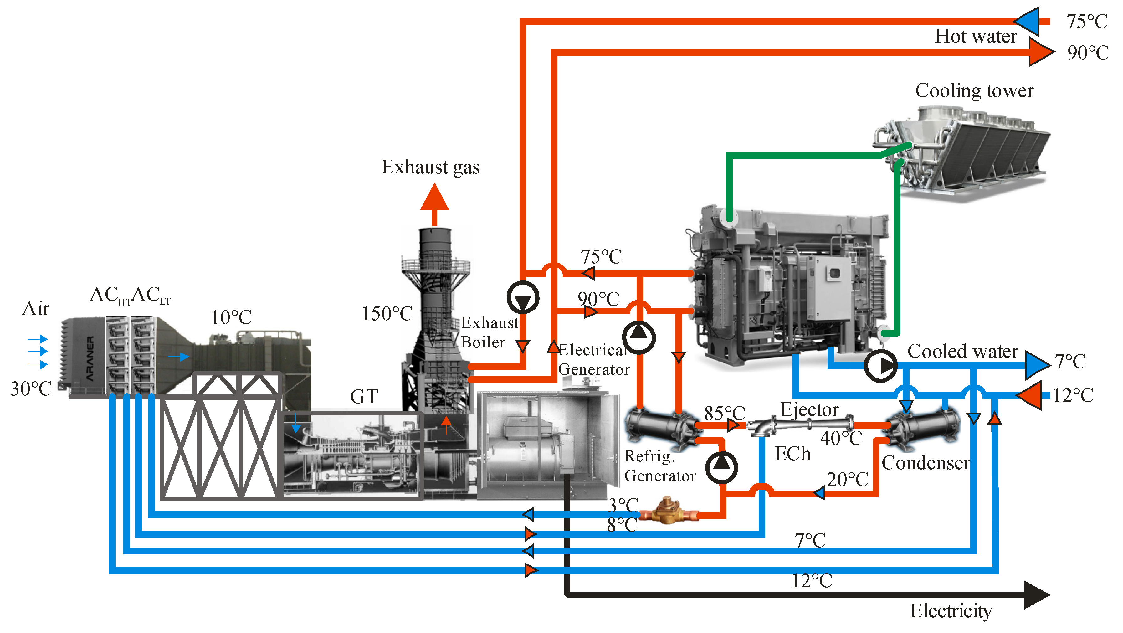
Figure 6.
The annual values of CDH versus specific cooling capacity q0 (a) and total fuel reduction ∑B versus overall cooling capacity Q0 (b) for ta2: 7 and 10 °C—in AECh; 15 °C—in ACh.
Figure 6.
The annual values of CDH versus specific cooling capacity q0 (a) and total fuel reduction ∑B versus overall cooling capacity Q0 (b) for ta2: 7 and 10 °C—in AECh; 15 °C—in ACh.
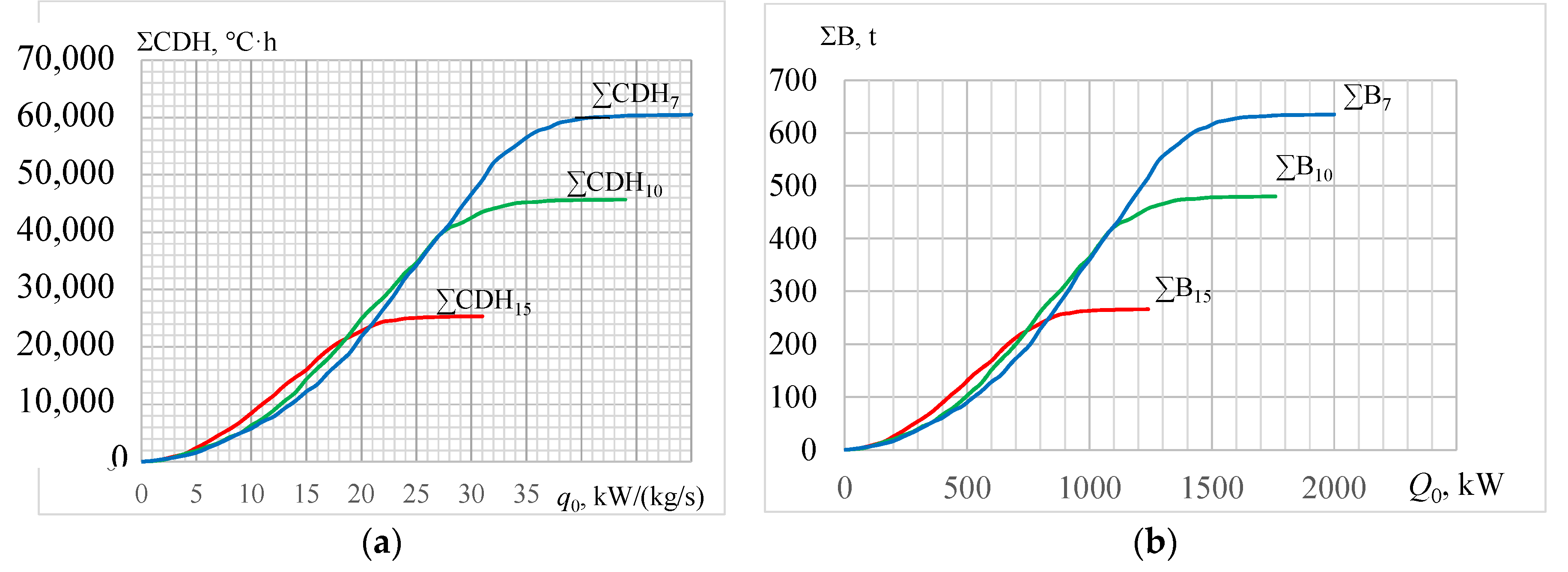
Figure 7.
The annual values of specific fuel reduction ∑Δbe against specific cooling capacity q0 at different temperatures of cooled air ta2: 7 and 10 °C—in AECh; 15 °C—in ACh.
Figure 7.
The annual values of specific fuel reduction ∑Δbe against specific cooling capacity q0 at different temperatures of cooled air ta2: 7 and 10 °C—in AECh; 15 °C—in ACh.

Figure 8.
Annual specific fuel reduction ∑b and its relative increment ∑b/q0 due to cooling ambient air to ta2 = 15 °C (a) and 10 °C (b) against specific cooling capacity q0: q0.opt and ∑bopt—optimal values.
Figure 8.
Annual specific fuel reduction ∑b and its relative increment ∑b/q0 due to cooling ambient air to ta2 = 15 °C (a) and 10 °C (b) against specific cooling capacity q0: q0.opt and ∑bopt—optimal values.

Figure 9.
Relative increments of annual specific fuel reduction ∑b/q0 and (∑b − ∑bopt)/q0 for ta2 = 15 °C (a) and 10 °C (b) against specific cooling capacity q0.
Figure 9.
Relative increments of annual specific fuel reduction ∑b/q0 and (∑b − ∑bopt)/q0 for ta2 = 15 °C (a) and 10 °C (b) against specific cooling capacity q0.

Figure 10.
Annual specific fuel reduction ∑b and relative increment of annual specific fuel reduction (∑b − ∑bopt)/q0 for ta2 = 15 °C (a) and 10 °C (b):·−(∑b − ∑bopt)/q0.
Figure 10.
Annual specific fuel reduction ∑b and relative increment of annual specific fuel reduction (∑b − ∑bopt)/q0 for ta2 = 15 °C (a) and 10 °C (b):·−(∑b − ∑bopt)/q0.
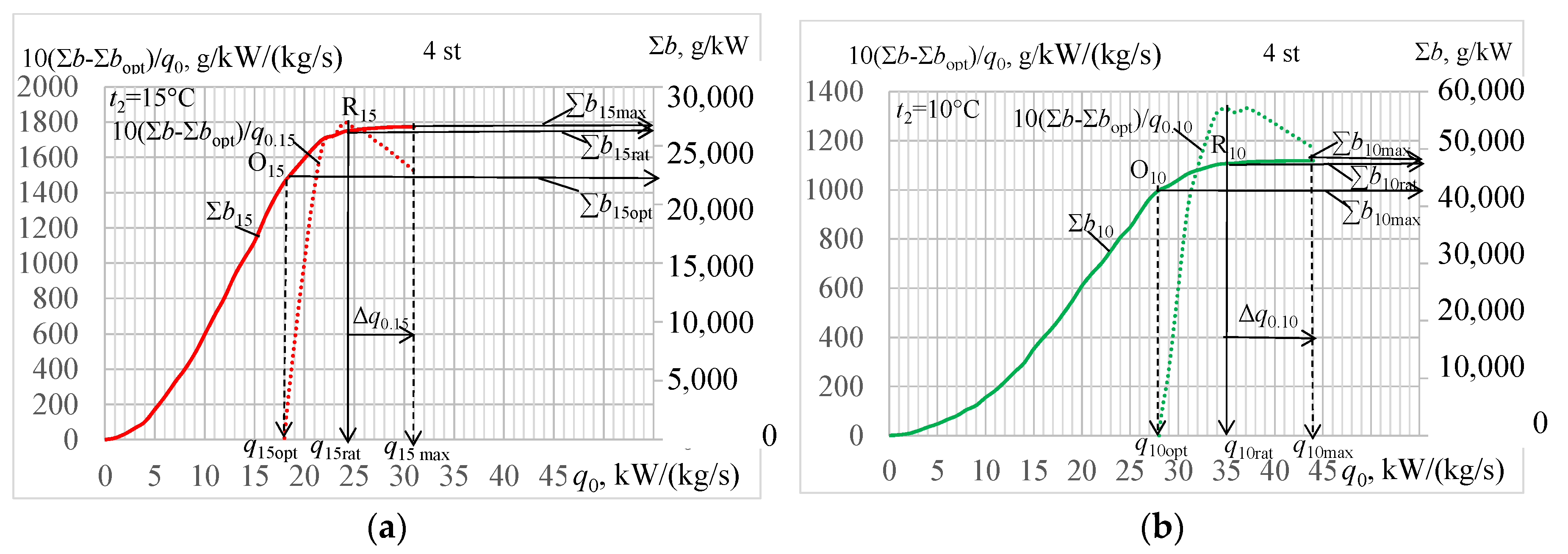
Figure 11.
Relative increment of annual specific fuel reduction ∑b/q0 and annual specific fuel reduction ∑b due to cooling air to ta2 = 7, 10 and 15 °C against a cooling capacity needed q0 (2 stage of methodology).
Figure 11.
Relative increment of annual specific fuel reduction ∑b/q0 and annual specific fuel reduction ∑b due to cooling air to ta2 = 7, 10 and 15 °C against a cooling capacity needed q0 (2 stage of methodology).
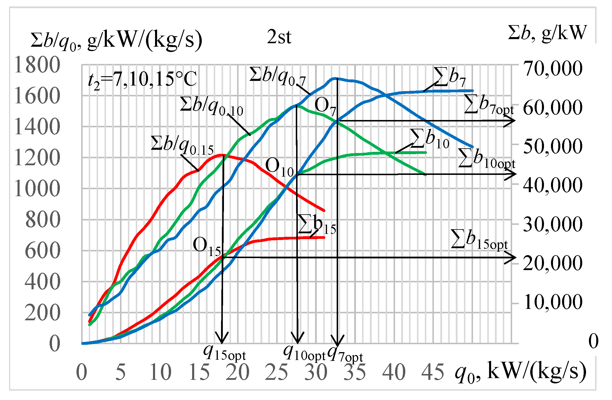
Figure 12.
Relative increments of annual specific fuel reduction ∑b/q0 and (∑b − ∑bopt)/q0∙due to cooling air ta2 = 7, 10 and 15 °C against specific cooling capacities needed q0 (3 stage): −∑b/q0; −(∑b − ∑bopt)/q0.
Figure 12.
Relative increments of annual specific fuel reduction ∑b/q0 and (∑b − ∑bopt)/q0∙due to cooling air ta2 = 7, 10 and 15 °C against specific cooling capacities needed q0 (3 stage): −∑b/q0; −(∑b − ∑bopt)/q0.
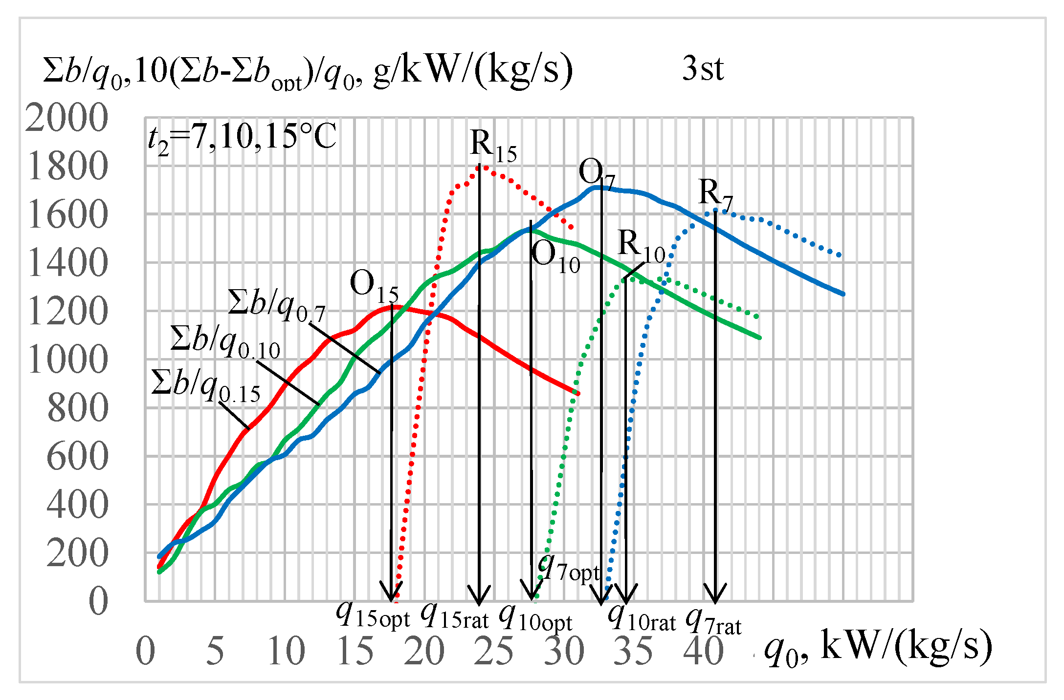
Figure 13.
Annual specific fuel reduction ∑b and its relative increments (∑b − ∑bopt)/q0∙for ta2 = 7, 10 and 15 °C: Δq0—reduction of design specific cooling capacity;·−(∑b − ∑bopt)/q0.
Figure 13.
Annual specific fuel reduction ∑b and its relative increments (∑b − ∑bopt)/q0∙for ta2 = 7, 10 and 15 °C: Δq0—reduction of design specific cooling capacity;·−(∑b − ∑bopt)/q0.
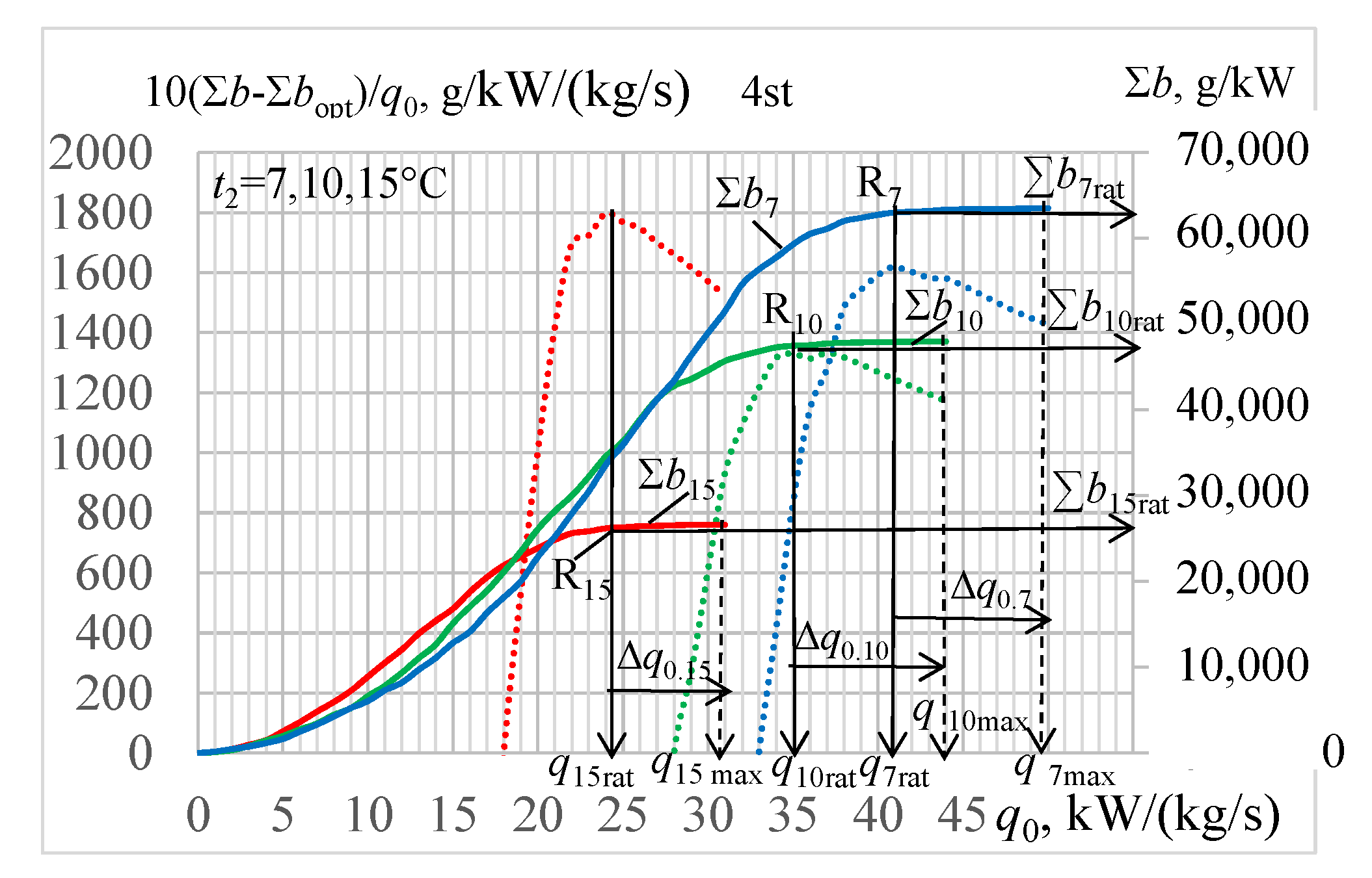
Figure 14.
Annual values of specific fuel reduction ∑b against specific cooling capacities q0 for ta2 = 7, 10 and 15 °C: Δq0—reduction of design specific cooling capacity.
Figure 14.
Annual values of specific fuel reduction ∑b against specific cooling capacities q0 for ta2 = 7, 10 and 15 °C: Δq0—reduction of design specific cooling capacity.
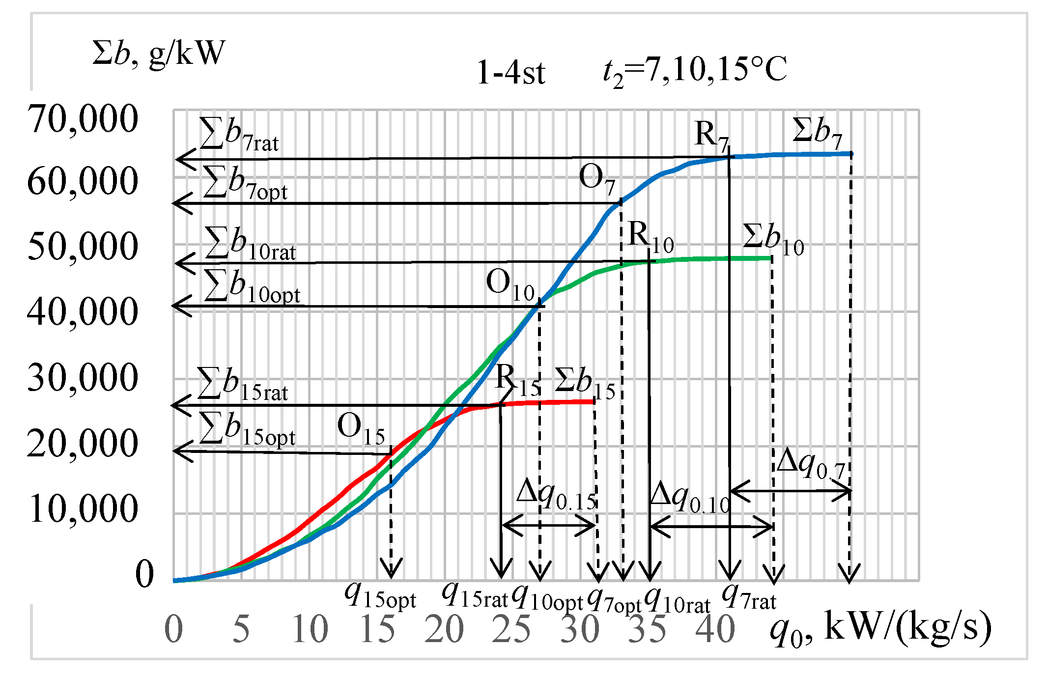
Figure 15.
Relative values of annual fuel reduction ∑b/bmax against relative cooling capacities q0/q0.max needed for cooling ambient air to ta2 = 7, 10 and 15 °C.
Figure 15.
Relative values of annual fuel reduction ∑b/bmax against relative cooling capacities q0/q0.max needed for cooling ambient air to ta2 = 7, 10 and 15 °C.

Publisher’s Note: MDPI stays neutral with regard to jurisdictional claims in published maps and institutional affiliations. |
© 2020 by the authors. Licensee MDPI, Basel, Switzerland. This article is an open access article distributed under the terms and conditions of the Creative Commons Attribution (CC BY) license (http://creativecommons.org/licenses/by/4.0/).
Share and Cite
MDPI and ACS Style
Radchenko, A.; Trushliakov, E.; Kosowski, K.; Mikielewicz, D.; Radchenko, M. Innovative Turbine Intake Air Cooling Systems and Their Rational Designing. Energies 2020, 13, 6201. https://doi.org/10.3390/en13236201
AMA Style
Radchenko A, Trushliakov E, Kosowski K, Mikielewicz D, Radchenko M. Innovative Turbine Intake Air Cooling Systems and Their Rational Designing. Energies. 2020; 13(23):6201. https://doi.org/10.3390/en13236201
Chicago/Turabian StyleRadchenko, Andrii, Eugeniy Trushliakov, Krzysztof Kosowski, Dariusz Mikielewicz, and Mykola Radchenko. 2020. "Innovative Turbine Intake Air Cooling Systems and Their Rational Designing" Energies 13, no. 23: 6201. https://doi.org/10.3390/en13236201
Note that from the first issue of 2016, this journal uses article numbers instead of page numbers. See further details here.