Numerical and Physical Simulation of Heat Transfer Enhancement Using Oval Dimple Vortex Generators—Review and Recommendations


Abstract
: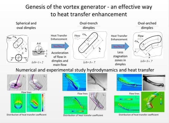
1. Introduction
2. Review of Numerical Simulation of Heat Transfer Enhancement Using Elongated Oval Dimples
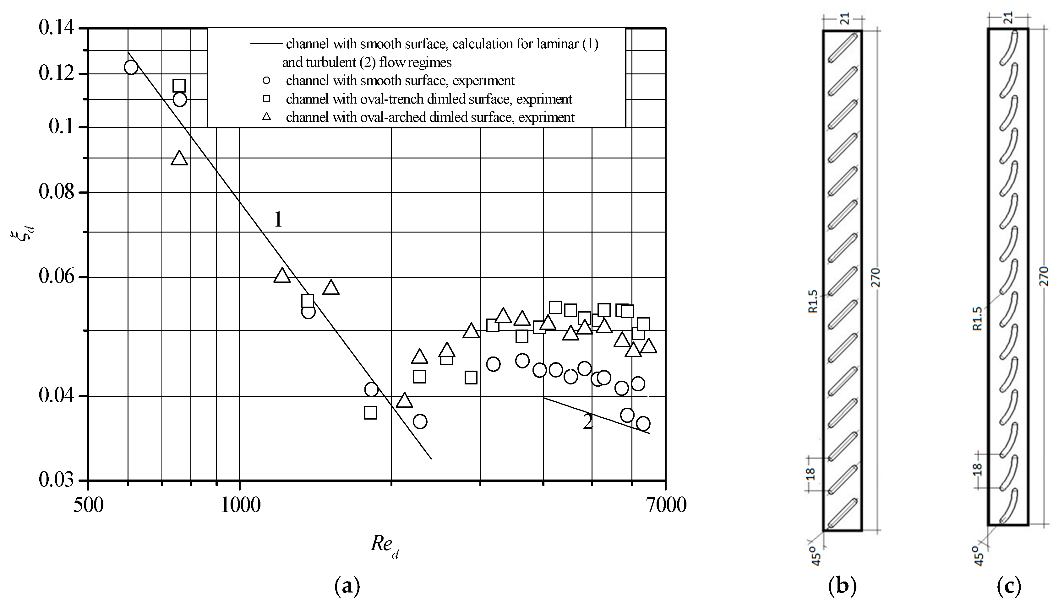
3. Experimental Methodology
4. Experimental Results
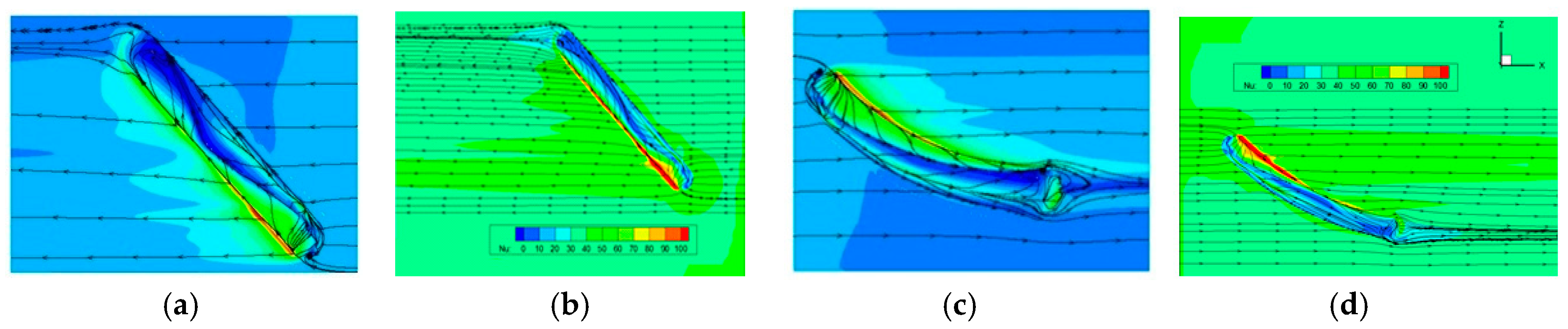
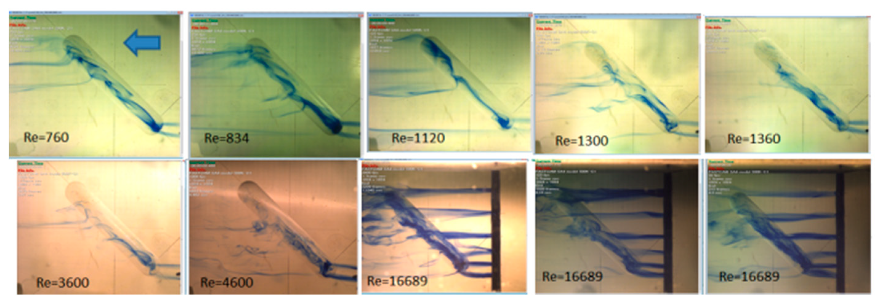
4.1. Analysis of the Flow Structure
4.2. Analysis of the Flow Structure
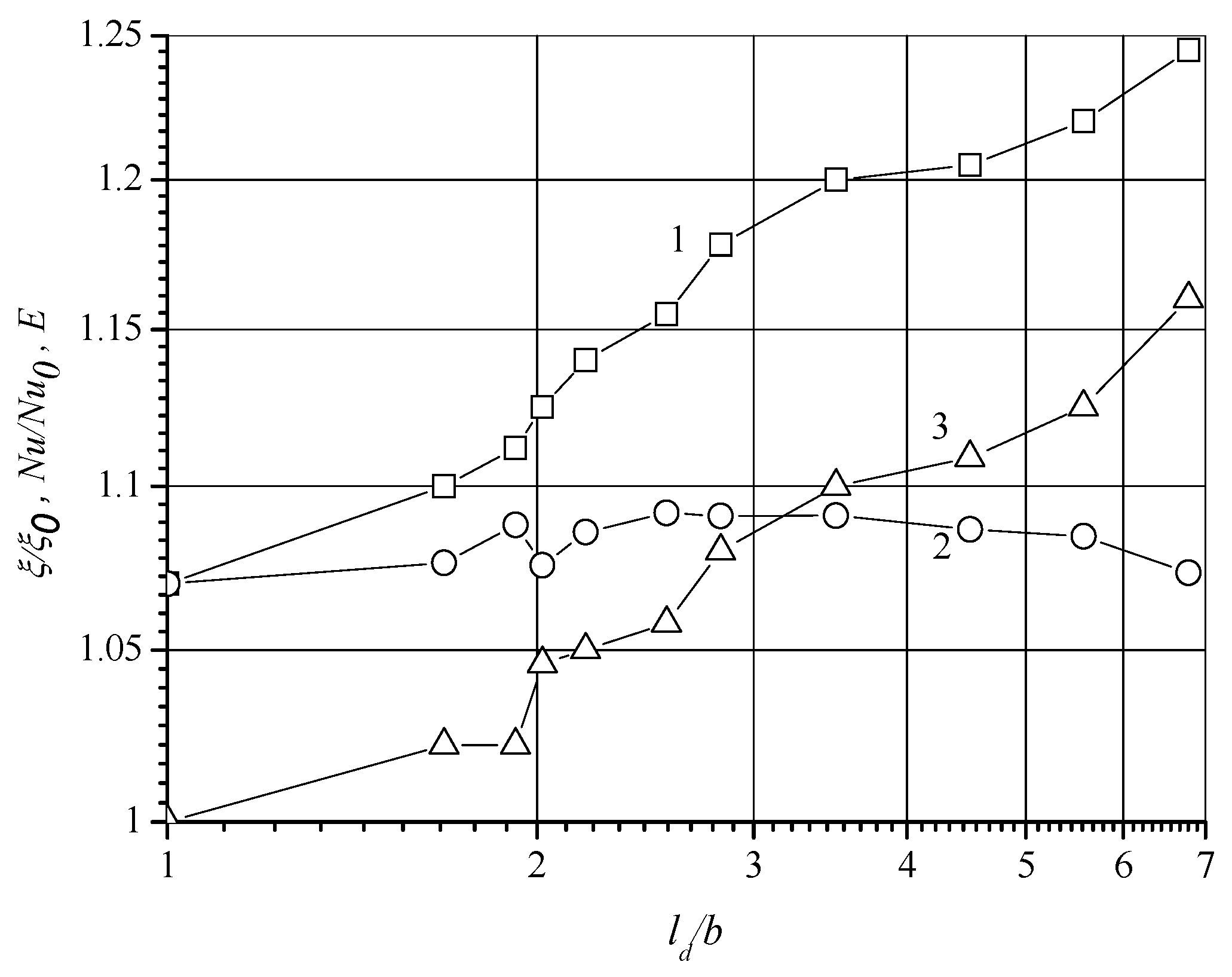
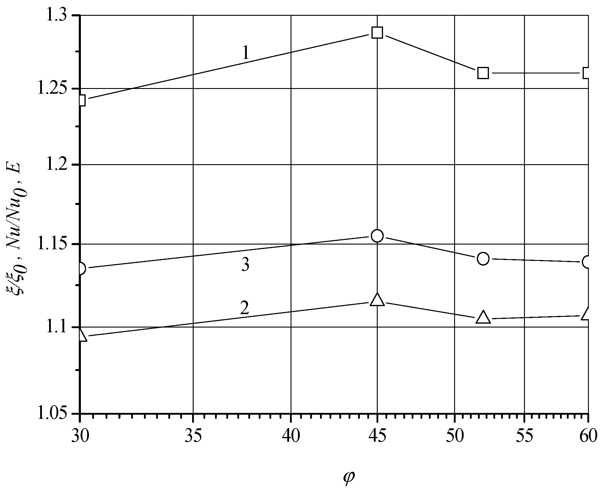
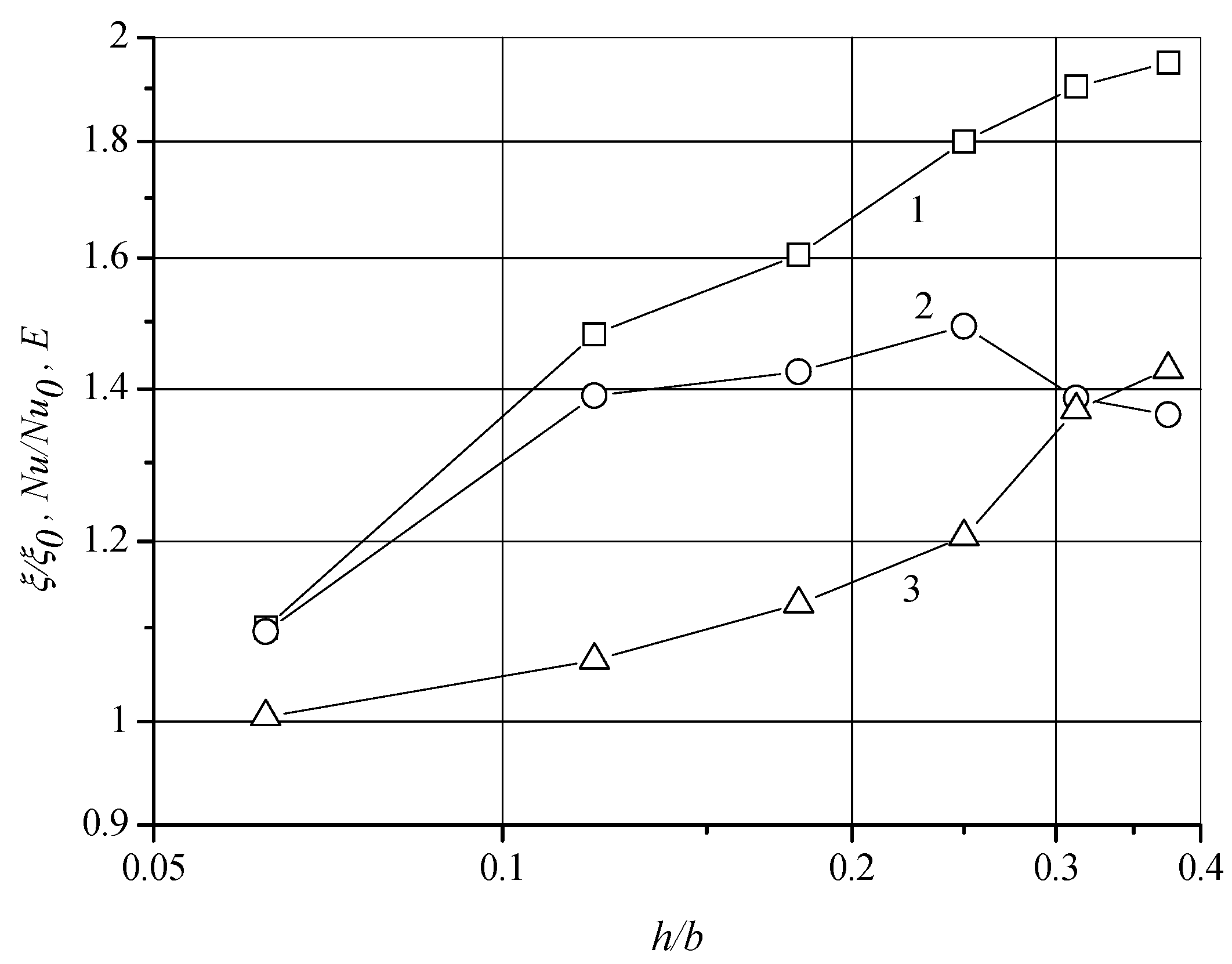
4.3. Verification and Recommendation
4.4. Artificial Neural Network Application
5. Conclusions
Author Contributions
Funding
Conflicts of Interest
Nomenclature
| A | area of the cross-section of the duct, m2; A = B·hch |
| B | a duct width, m; |
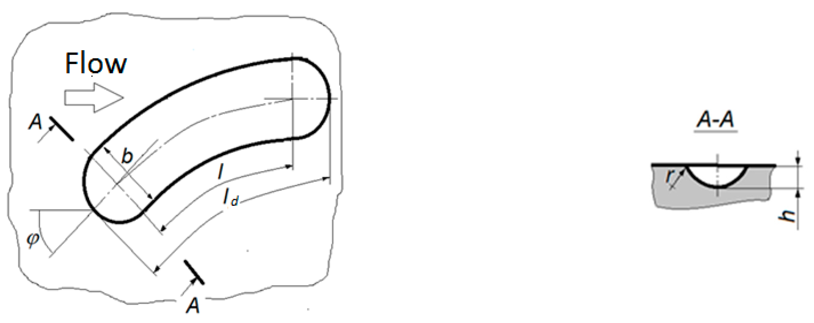
| b | a dimple width, m; |
| c | heat capacity, J/kg·K |
| de | equivalent diameter of the duct, m; de = 4·A/P |
| h | a dimple depth, m; |
| hch | a duct height, m; |
| L | a duct length, m; |
| l | a length of the trench part of the dimple, m; |
| ld | a total length, m; |
| mass flow rate, kg/s | |
| P | perimeter of the cross-section, m |
| Q | heat flow supplied from the surface, W |
| R | the dimple forming radius, m |
| r | an edge rounding radius, m; |
| S | a notching step, m |
| T | temperature, K |
| Tf | a temperature of the flow, K |
| Tw | a temperature of the wall, K |
| mean flow velocity, m/s; | |
| Greek symbol: | |
| α | a heat transfer coefficient, W/m2K; |
| α0 | a heat transfer coefficient for the smooth surface, W/m2K: |
| ΔP | a pressure drop, Pa |
| ΔT | surface to flow mean temperature difference, K; ΔT = Tw − Tf |
| λ | a heat conductivity coefficient, W/m2K |
| μ | a dynamic viscosity, Pa·s |
| ξ | a Darcy-Weibach friction factor; ξ = 2·ΔPhch/(ρ L) |
| ξ0 | a friction factor value for the smooth surface; ξ0 = 2·ΔP·hch/(ρ L) |
| ξd | a friction factor value for the dimpled surface; ξd = 2·ΔP·de/(ρ L) |
| ξd0 | a friction factor for the surface without the dimples; ξd0 = 2·ΔP de/(ρ L) |
| ρ | a density of fluid, kg/m3 |
| φ | an angle of attack of the dimple (to the main flow), deg, |
| Dimensionless complexes: | |
| E | a thermohydraulic efficiency coefficient; E = (Nu/Nu0)/(ξ/ξ0) = (Nud/Nud0)/(ξd/ξd0) |
| Emax | a maximal value of thermohydraulic efficiency |
| Nu | a Nusselt number, Nu = αhch/λ |
| Nu0 | a Nusselt number for the smooth surface, Nu0 = α0hch/λ |
| Nud | a Nusselt number for the dimpled surface, Nud = αde/λ |
| Nud0 | a Nusselt number for the surface without the dimples, Nud0 = α0de/λ |
| Nu/Nu0 | a Nusselt number augmentation ratio; Nu/Nu0 = Nud/Nud0 = α/α0 |
| Pr | a Prandtl number, Pr = μc/ρ |
| Re | a Reynolds number based on the duct height; Re = ρhch/μ |
| Red | a Reynolds number based on the equivalent diameter of the duct; Red = ρe/μ |
| ξ/ξ0 | a friction factor augmentation value; ξ/ξ0 = ξd/ξd0 |
References
- Rashidi, S.; Hormozi, F.; Sunden, B.; Mahia, O. Energy Saving in Thermal Energy Systems Using Dimpled Surface Technology—A review on mechanisms and applications. Appl. Energy 2019, 250, 1491–1547. [Google Scholar] [CrossRef]
- Shchukin, A.V.; Kozlov, A.P.; Agachev, R.S.; Chudnovsky, Y.P. Intensification of Heat Exchange by Spherical Dimples under the Influence of Perturbing Factors; Kazan State Technical University: Kazan, Russia, 2003; p. 143. [Google Scholar]
- Khalatov, A.A. Heat Transfer and Hydrodynamics near Surface Depressions (Dimples); Instutute of Technical Thermal Physics: Kiev, Ukraine, 2005; p. 76. [Google Scholar]
- Kiknadze, G.I.; Gachechiladze, I.A.; Alekseev, V.V. Self-Organization of Tornado-Like Jets in Flows of Viscous Continuous Media and Intensification of Heat and Mass Transfer; Publishing House of Moscow Power Engineering Institute: Moscow, Russia, 2005; p. 82. [Google Scholar]
- Bystrov, Y.A.; Isaev, S.A.; Kudryavtsev, N.A.; Leontiev, A.I. Numerical Simulation of Vortex Heat Transfer Intensification in Tube Packages; Sudostroenie: Saint Petersburg, Russia, 2005; p. 398. [Google Scholar]
- Dzyubenko, B.V.; Kuzma-Kichta, Y.A.; Leontiev, A.I.; Fedik, I.I.; Holpanov, L.P. Intensification of Heat and Mass Transfer on Macro-, Micro- and Nanoscales; CNIIATOMINFORM: Moscow, Russia, 2008; p. 532. [Google Scholar]
- Gortyshov, Y.F.; Popov, I.A.; Olympiev, V.V.; Shchelchkov, A.V.; Kaskov, S.I. Thermohydraulic Efficiency of Perspective Methods of Heat Transfer Intensification in Heat Exchange Equipment Channels; Center of Innovative Technologies: Kazan, Russia, 2009; p. 531. [Google Scholar]
- Sokolov, N.P.; Polishchuk, V.G.; Andreev, K.L. Heat Transfer and Hydraulics in Channels with Dimpled Surfaces; Polytechnic University Publishing House: Saint Petersburg, Russia, 2012; p. 288. [Google Scholar]
- Gotovsky, M.A.; Demenok, S.L.; Medvedev, V.V.; Sivukha, S.M. Heat Transfer and Resistance of Channels with Dimpled Surfaces; Strata: Saint Petersburg, Russia, 2016; p. 211. [Google Scholar]
- Leontiev, A.I.; Alekseenko, S.V.; Volchkov, E.P.; Dzubenko, B.V.; Dragunov, Y.G.; Isaev, S.A.; Koroteev, A.A.; Kuzma-Kichta, Y.A.; Popov, I.A.; Terekhov, V.I. Vortical Technologies for Power Engineering; Publishing House of Moscow Power Engineering Institute: Moscow, Russia, 2017; p. 350. [Google Scholar]
- Isaev, S.A.; Leontiev, A.I.; Mityakov, A.V.; Pyshny, I.A. Intensification of Tornado Turbulent Heat Transfer in Asymmetric Wells on a Flat Wall. J. Eng. Phys. Thermophys. 2003, 76, 31–34. [Google Scholar]
- Isaev, S.A.; Popov, I.A.; Leontiev, A.I.; Gultsova, M.E. Transformation and Intensification of Tornado-Like Flow in a Narrow Channel during Elongation of an Oval Dimple with Constant Area. Tech. Phys. Lett. 2015, 41, 606–612. [Google Scholar] [CrossRef]
- Isaev, S.A.; Schelchkov, A.V.; Leontiev, A.I.; Gortyshov, Y.F.; Baranov, P.A.; Popov, I.A. Tornado-Like Heat Transfer Enhancement in the Narrow Plane-Parallel Channel with the Oval-Trench Dimple of Fixed Depth and Spot Area. Int. J. Heat Mass Transf. 2017, 109, 40–62. [Google Scholar] [CrossRef]
- Isaev, S.; Leontiev, A.; Chudnovsky, Y.; Popov, I. Vortex Heat Transfer Enhancement in Narrow Channels with a Single Oval-Trench Dimple Oriented at Different Angles to the Flow. J. Enhanc. Heat Transf. 2018, 25, 579–604. [Google Scholar] [CrossRef]
- Isaev, S.A.; Baranov, P.A.; Leontiev, A.I.; Popov, I.A. Intensification of a Laminar Flow in a Narrow Microchannel with Single-Row Inclined Oval-Trench Dimples. Tech. Phys. Lett. 2018, 44, 398–400. [Google Scholar] [CrossRef]
- Isaev, S.A.; Leontiev, A.I.; Milman, O.O.; Popov, I.A.; Sudakov, A.G. Influence of the Depth of Single-Row Oval-Trench Dimples Inclined to Laminar Air Flow on Heat Transfer Enhancement in a Narrow Micro-Channel. Int. J. Heat Mass Transf. 2019, 134, 338–358. [Google Scholar] [CrossRef]
- Isaev, S.A.; Leontiev, A.I.; Baranov, P.A.; Popov, I.A.; Shchelchkov, A.V.; Gortyshov, Y.F.; Skrypnik, A.N.; Mironov, A.A. Heat Exchange Surface. Patent No. 2 684 303. Russian Federation, IPC7 F28F 3/04. Published: 05.04.2019. Byul. No. 10. Priority 13.06.2018. Available online: https://www.fips.ru/iiss/document.xhtml?faces-redirect=true&id=a7dfd30ed95db609149ac796e1758915 (accessed on 27 September 2020).
- Isaev, S.A.; Gritckevich, M.S.; Leontiev, A.I.; Popov, I.A.; Sudakov, A.G. Abnormals Intensification of Turbulent Separated Flow in Inclined Single-Row Oval-Trench Wells on the Wall of a Narrow Channel. High Temp. 2019, 57, 797–800. [Google Scholar] [CrossRef]
- Isaev, S.A.; Gritskevich, M.S.; Leontiev, A.I.; Milman, O.O.; Nikushchenko, D.V. Acceleration of the Turbulent Flow in a Narrow Oblong Channel and Intensification of the Detached Flow when Compacting Single-Row Inclined Oval-Trench Wells on the Wall. Thermophys. Aeromech. 2019, 26, 697–702. [Google Scholar] [CrossRef]
- Isaev, S.A.; Gritckevich, M.S.; Leontiev, A.I.; Milman, O.O.; Nikushchenko, D.V. NT Vortex Enhancement of Heat Transfer and Flow in the Narrow Channel with a Dense Packing of Inclined One-Row Oval-Trench Dimples. Int. J. Heat Mass Transf. 2019, 145, 118737. [Google Scholar] [CrossRef]
- Kiselev, N.A.; Burtsev, S.A.; Strongin, M.M.; Vinogradov, Y.A. Experimental Study of Heat Transfer and Resistance of Complex-Shaped Dimples. In Fundamental and Applied Problems of Heat and Mass Transfer. Proceedings of the Anniversary Conference of the National Committee of the Russian Academy of Sciences on Heat and Mass Transfer; Publishing House of Moscow Power Engineering Institute: Moscow, Russia, 2017; pp. 124–127. [Google Scholar]
- Voskoboynik, A.V. Passive Control of the Formation of Vortex Structures inside a Semi-Cylindrical Dimples. Bull. Donetsk Natl. Univ. Ser. A Nat. Sci. 2009, 1, 173–182. [Google Scholar]
- Voropaev, G.A.; Voskoboynik, A.V.; Voskoboynik, V.A.; Isaev, S.A. Visualization of Laminar Flow around Oval Dimples. Appl. Hydraul. Mech. 2009, 11, 31–36. [Google Scholar]
- Sergievsky, E.D.; Arbatsky, A.A. Intensification of Heat Exchange by Applying Oval Dimples to the Heat Exchange Surface. In Proceedings of the Fifth Russian National Conference on Heat Exchange, Moscow, Russia, 26–29 October 2010; Publishing House of Moscow Power Engineering Institute: Moscow, Russia, 2010; Volume 6, pp. 141–144. [Google Scholar]
- Popov, I.A.; Shchelchkov, A.V.; Ryzhkov, D.V.; Ulyanova, R.A. Vortex Formation in Separated Flows on Surfaces with Dimples of Various Shapes. Proc. Akad. 2010, 3, 7–14. [Google Scholar]
- Isaev, S.A.; Leontiev, A.I.; Baranov, P.A.; Popov, I.A.; Shchelchkov, A.V.; Gortyshov, Y.F.; Skrypnik, A.N.; Mironov, A.A. Heat Exchange Surface. Patent No. 2 716 958. Russian Federation, IPC7 F28F 3/04. Published: 17.03.2020. Byul. No. 8. Priority 26.07.2019. Available online: https://www.fips.ru/iiss/document.xhtml?faces-redirect=true&id=17825c9832e585d2fc610d2946294113 (accessed on 27 September 2020).
- Jambunathan, K.; Hartle, S.L.; Ashforth-Frost, S.; Fontama, V.N. Evaluating Convective Heat Transfer Coefficients Using Neural Networks. Int. J. Heat Mass Transf. 1996, 39, 2329–2332. [Google Scholar] [CrossRef]
- Zdaniuk, G.J.; Chamra, L.M.; Walters, D.K. Correlating Heat Transfer and Friction in Helically-Finned Tubes Using Artificial Neural Networks. Int. J. Heat Mass Transf. 2007, 50, 4713–4723. [Google Scholar] [CrossRef]


| Surface Type | Dimple Type | Relative Dimple Size | Flow Parameters | Nu/Nu0 | ξ/ξ0 | Emax | ||
|---|---|---|---|---|---|---|---|---|
| h/b | ld/b | Red | Pr | |||||
| Multi row | Oval-trench | 0.25 | 7 | 4·103–2 × 10⁴ | 0.72 | 2.3–2.43 | 2.5–3 | 0.97 |
| Oval-arched | ~2.5 | 2.3–2.6 | 1.11 | |||||
| Single rowe | Oval-trench | 0.33 | 3200–9 × 10⁴ | 1.2–1.55 | ~1.4 | 1.11 | ||
| Oval-arched | 1.2–1.71 | ~1.25 | 1.37 | |||||
© 2020 by the authors. Licensee MDPI, Basel, Switzerland. This article is an open access article distributed under the terms and conditions of the Creative Commons Attribution (CC BY) license (http://creativecommons.org/licenses/by/4.0/).
Share and Cite
Mironov, A.; Isaev, S.; Skrypnik, A.; Popov, I. Numerical and Physical Simulation of Heat Transfer Enhancement Using Oval Dimple Vortex Generators—Review and Recommendations. Energies 2020, 13, 5243. https://doi.org/10.3390/en13205243
Mironov A, Isaev S, Skrypnik A, Popov I. Numerical and Physical Simulation of Heat Transfer Enhancement Using Oval Dimple Vortex Generators—Review and Recommendations. Energies. 2020; 13(20):5243. https://doi.org/10.3390/en13205243
Chicago/Turabian StyleMironov, Alexander, Sergey Isaev, Artem Skrypnik, and Igor Popov. 2020. "Numerical and Physical Simulation of Heat Transfer Enhancement Using Oval Dimple Vortex Generators—Review and Recommendations" Energies 13, no. 20: 5243. https://doi.org/10.3390/en13205243
APA StyleMironov, A., Isaev, S., Skrypnik, A., & Popov, I. (2020). Numerical and Physical Simulation of Heat Transfer Enhancement Using Oval Dimple Vortex Generators—Review and Recommendations. Energies, 13(20), 5243. https://doi.org/10.3390/en13205243