Article

Online High Performance Genetic Algorithm Based Sliding Mode Control for Controllable Pitch Propeller

College of Automation, Harbin Engineering University, Harbin 150001, China
*
Author to whom correspondence should be addressed.
Processes 2020, 8(8), 953; https://doi.org/10.3390/pr8080953
Submission received: 17 June 2020 / Revised: 29 July 2020 / Accepted: 3 August 2020 / Published: 7 August 2020
(This article belongs to the Section Process Control and Monitoring)

Abstract

:
During the voyage of a ship, the performance of a controllable pitch propeller (CPP) is severely affected by the changing load demand and ever-present disturbance from ocean waves, which will also result in model uncertainty. In order to improve the performance of the CPP system, an online high-performance genetic algorithm (HPGA)-based sliding mode control (SMC) strategy is proposed. Firstly, the model of the CPP system is obtained according to the manufacturer’s instructions. Then, a chattering-free sliding mode controller (CF-SMC) is designed for the CPP system, after which the parameters in the CF-SMC are optimized with the HPGA method. Finally, the optimized CF-SMC is applied to an experimental setup of a prototype CPP system. In order to validate the effectiveness of the proposed method, it is compared with a proportional-integral-derivative (PID) controller, which is typically applied on real CPP-systems, with results indicating the superiority of the proposed method.

1. Introduction

During the voyage, the disturbance from the sea is ever-present, and the operation mode (slam start, crash stop, sever turning circles, etc.) changes which will result in varying load and model uncertainty in the CPP system. Due to the extremely harsh environment in the sea, it is difficult to design a controller for the CPP system with satisfying performance. The behavior of the CPP actuating mechanism is greatly related to the angle of the blades. The varying load acting on the blades can result in problems such as high pressures in the actuating system and response delays, which are ultimately responsible for most mechanism failures [1]. Hence, it is important to develop advanced control methods to ensure the safe operation of the CPP system.
The CPP systems have been applied in different areas, including ships, airplanes, helicopters, windmills, and other dynamical systems. In ship applications, they serve the voyage speed and orientation. Due to the lower inertia of blades compared to a whole propeller, the dynamics of the ship are much faster with the CPP system [2]. In aerospace applications, it is well-known that the CPP system is used to adapt the airplane to different thrust levels and air speeds with active blades [3].
In the presence of frequently changing loads, an effective and robust control system must be developed to obtain a precise position control of the blades. A variety of controllers for a CPP system have been proposed in the literature. Applying a fuzzy controller was presented for improving wind energy capture for variable-speed wind turbines [4]. A novel model predictive control was designed to solve the problem of individual pitch control of wind turbines, and by linearizing the nonlinear model for different operation points, control in the full load region was resolved [5]. CPP system optimizations for fast ferries and ships are presented in Reference [6] and Reference [7], and examples for aerospace applications are presented in Reference [8]. The applications for a windmill are presented in Reference [9] and Reference [10]. The studies on the CPP systems are mainly about the optimization for the angle of the blades, and there are few studies on how to reach the optimal angle. In this paper, an online HPGA-based sliding mode controller is designed for the CPP system to reach the desired pitch as quickly as possible.
Sliding mode control (SMC) is a robust control method to deal with plant model uncertainties, load disturbances, and parameter mismatch [11]. Hence, SMC is selected to deal with the control problems in the CPP system. So far, the SMC method has been successfully applied to some industrial processes, including areas such as electrical, mechanical, chemical, and aerospace engineering [12,13]. A quasi-continuous high-order sliding mode control based on an adaptive fuzzy controller was applied to an output feedback tracking control scheme with only a position measurement. With this scheme, the chattering phenomenon is eliminated effectively [14]. A minimum sliding mode control error feedback controller was applied to input-output linearization to improve the control precision of nonlinear spacecraft formation flying in Reference [15]. A combination of feedforward control with feedback control was developed to solve the control difficulties existing in systems with large nonlinearity and time delay [16], and the sliding mode algorithm is employed to improve the robustness of the system. On the control problem of permanent-magnet synchronous servo motor, a recurrent-fuzzy-neural-network (RFNN) sliding mode control system was investigated, where RFNN was used to overcome the two main problems with sliding mode control, i.e., the assumption of known uncertainty bounds and the chattering phenomena in the control effort [17]. However, a switching term exists in the SMC method, which can generate high-frequency oscillations in the system inputs and limit the application of SMC in practical systems. Therefore, a number of methods for chattering elimination have been studied.
By adopting a saturation function to the SMC strategy, a boundary layer method was proposed [18]. However, in this method, the steady tracking errors will increase. In order to eliminate the chattering, the discontinuous item is hidden in its higher derivatives in the high-order sliding mode control approach [19,20,21,22,23]. The disturbance estimation method was also developed to attenuate the chattering [24]. Through disturbance estimation techniques, a continuous sliding mode control that features second-order nonlinear dynamics in the boundary layer was designed. A chattering-free sliding mode control was also studied for a discrete-time system by employing a continuous function instead of the switching term, and also a reach process was added in this method [25]. A chattering-free terminal sliding mode control was proposed to solve the singularity problem in a terminal sliding mode control system and the associated chattering problem [26], but this control strategy only obtained a continuous control output, not a smooth one which is required in most process controls. In this paper, a smooth SMC is designed to get an ideal control performance of the CPP system by putting the switching term into the second derivative of control output u; then, the control output u is smooth and its derivative is continuous.
In recent years, the genetic algorithm (GA) has been widely applied for its robust optimal capacity [27]. The genetic algorithm was applied to the online estimation of the state of power, and the problem of long-timescale estimation was solved [28]. A high-performance genetic algorithm using a bacterial conjugation operator to simplify the operation of the GA was raised [29], and due to the low optimization time, the simplified method can be applied in a real-time optimization process. A fuzzy-controlled genetic-based carpool algorithm combining the genetic algorithm and the fuzzy control system was proposed to optimize the route and match assignments of the requesters in the intelligent carpool system [30]. In the literature [31], an integrated equipment-workforce service planning problem was solved using the genetic algorithm-based decomposition approach. In the shipbuilding industry, an efficient genetic algorithm was applied to assembly sequence planning [32]. Due to a large amount of computation required, it is usually difficult to realize an online optimization with the GA method. In this paper, a high-performance GA using fewer computations is designed to realize the online optimization.
Stable and precise control of the blade is of great importance for the economical and safe operation of the CPP system. In order to have a satisfying performance of a CPP system, the online HPGA-based sliding mode controller is designed. Firstly, according to the manufacturer’s instructions of the main equipment in the CPP system, the model of the CPP system is obtained. Secondly, a smooth sliding mode controller is designed for the CPP system with optimized control parameters by HPGA. Thirdly, through a parameter estimator, HPGA generates optimized control parameters in real-time for a sliding mode controller based on the estimated model. Finally, an online HPGA-based sliding mode controller is obtained for CPP systems.
The rest of this paper is organized as follows. In Section 2, the scale model of the CPP system and its dynamic model are described. In Section 3, the principle of the online HPGA-based sliding mode controller is presented. The effectiveness of the proposed method is validated using numerical simulation and experiments on a scale model in Section 4. The conclusions are given in Section 5.

2. CPP System Description and Modeling

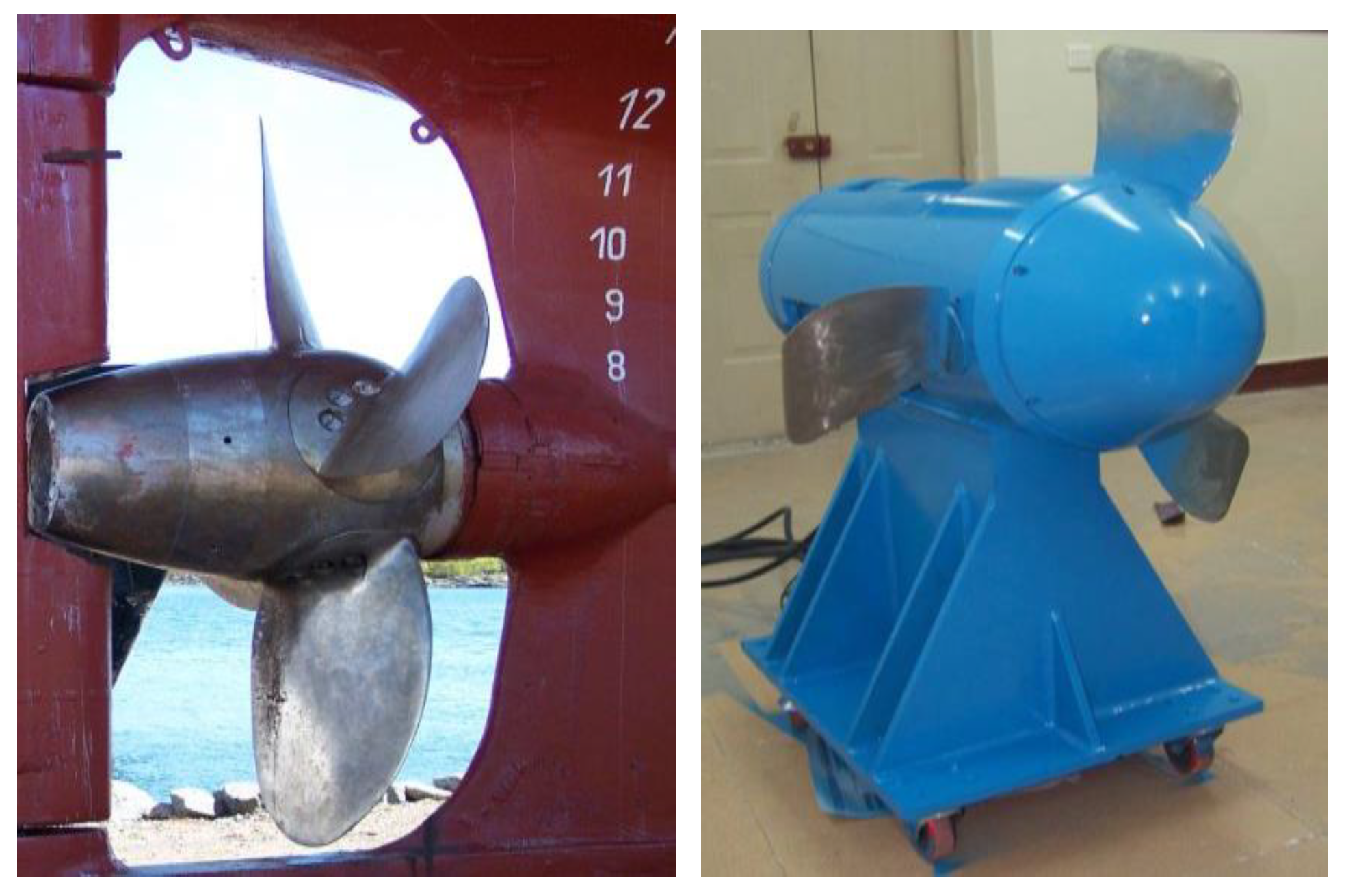
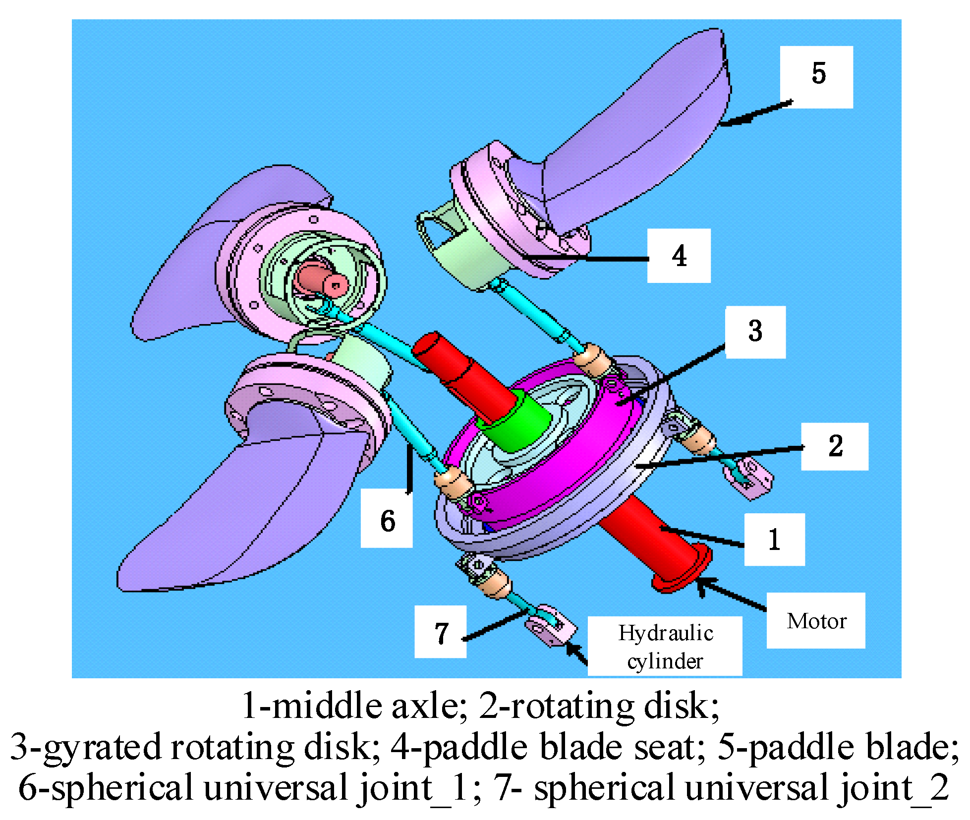
2.1. Description of the CPP System

The actual CPP system and its scale model are shown in Figure 1. The CPP system consists of a hydraulic cylinder, rotating disk (outside), gyrated rotating disk (inside), and spherical universal joints. The motion relationships of each component are shown in Figure 2. There are two kinds of operating modes of the CPP system.
(a)
Normal forward propulsion. The rotating disk moves axially in parallel when the three hydraulic cylinders are kept in the same position.
(b)
Arbitrary direction propulsion. The inside part of the rotating disk moves in a periodic way by keeping the three hydraulic cylinders in different positions.
The advantages of the controllable pitch propeller can be summarized as follows [33]:
(1)
The ship can operate in a forward or arbitrary direction with the CPP system, without changing the direction of rotation of the engine.
(2)
A non-reversible engine can be used for both forward and astern operation of the ship.
(3)
Since the pitch of the propeller determines the amount of thrust generated by the propeller, a change in the pitch angle can bring certain changes in the speed of the ship without changing the speed or rpm of the main engine.
(4)
In the case of astern operation, the efficiency is higher with the CPP system than that with fixed pitch propellers.
The goal of this work is to obtain fast and accurate control of the pitch angle, which is closely associated with the position of the hydraulic cylinder. Figure 3 illustrates the concept of the system, where C indicates the position controller. The output variable in the CPP system is the position of the hydraulic cylinder that needs to be controlled by manipulating the opening of the hydraulic valve. The position feedback of the hydraulic valve is realized by a grating ruler.

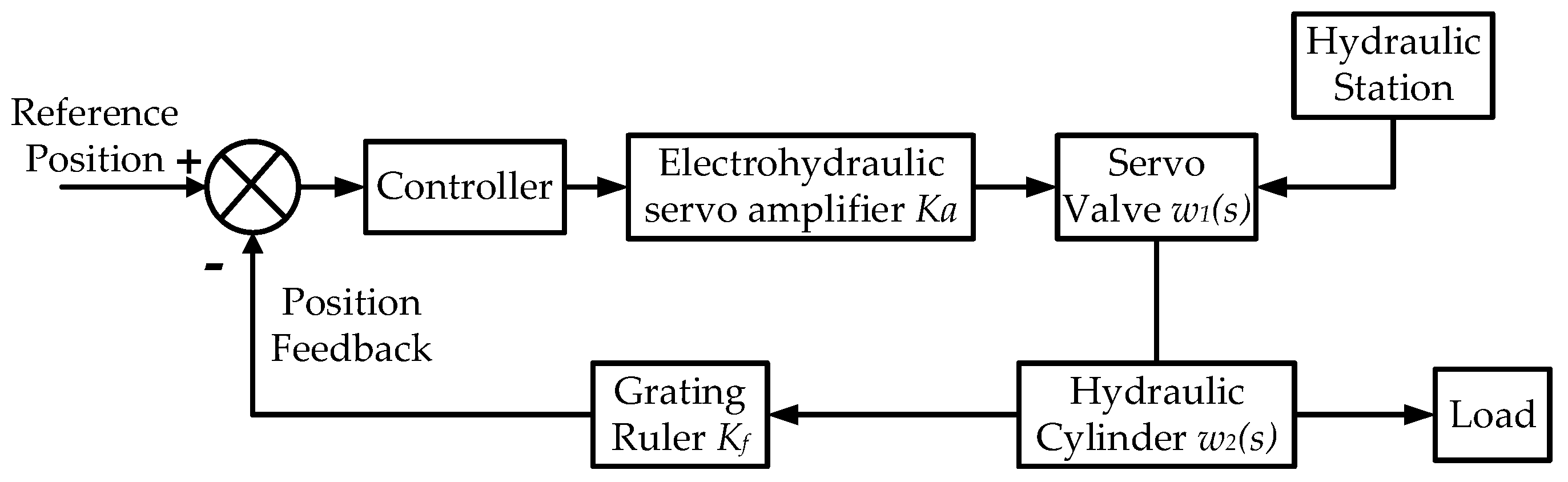
2.2. Modeling of the CPP System

According to the block diagram of the CPP control system, the main equipment consists of the servo valve, hydraulic cylinder, grating ruler, and electrohydraulic servo amplifier.
In the scale model of the CPP system, the servo valve is selected as a CSDY-I type jet pipe electro-hydraulic servo valve. The rated current of the servo valve is ±8 mA, and the rated pressure is 21 MPa. According to the manufacturer’s manual, the model of the servo valve can be expressed as [34]:
w 1 ( s ) = K s 2 w n + 2 ζ w n s + 1
where K is the gain of valve flow with the unit of L/(min·mA). w n represents the natural frequency with the unit of Hz ( w n is usually selected as the frequency where the valve phase lags 90°). ζ denotes the damping ratio, and it is a dimensionless parameter. The frequency response of the servo valve is shown in Figure 4, from where we can obtain the values: w n = 85   Hz and ζ = 0.8 .
The gain of valve flow can be obtained as [34]:
K = Q L I e = Q N I e P S P L P T P N
where QL and QN are load flow and rated flow with unit of L/min; Ie denotes the rated current with unit of mA; PS, PL, PT and PN are supply pressure, pressure drop on load, return pressure, and rated pressure of the oil with units of MPa, respectively.
The servo valve has many nonlinearities, such as switch saturations, hysteresis, and attracted property. In this paper, the switch saturations are not considered in the modeling part. They are taken into account in the validation part: a saturation limit is added considering the rated current of the servo valve in the simulation part; and the controller output is set between −8 mA to +8 mA to keep the servo valve working safely in the experiment part. Regarding the hysteresis and attracted property, they are treated as the parameter’s uncertainties in the model. As the chattering-free sliding mode control has the superiority in dealing with the parameter uncertainty of the system, the control system can still stay stable without taking these nonlinearities into account.
The hydraulic cylinder selected in the CPP system is a double-outlet symmetrical hydraulic cylinder. Excluding leakage, when the piston is moving, the amount of oil entering and exiting is the same. The speed of the piston in both directions is equal, and the characteristics are symmetrical. The parameters of the hydraulic cylinder are shown in Table 1.
The continuous equation for hydraulic cylinder flow can be summarized as [35]:
Q i n Q o u t = d V t d t + V t β e d p d t
The following differential equation can be derived from (3):
Q L = A d y d t + C t c p + V t 4 β e · d p d t
The force balance equation between the load and hydraulic cylinder can be computed as:
p L = 1 A ( m d 2 y d t 2 + B c d y d t + K y ) + F A
According to Equation (4) and Equation (5) the model of hydraulic cylinder can be obtained as:
w 2 ( s ) = 1 A s ( V t m 4 β e A 2 s 2 + ( m C t c A 2 + V t B c 4 β e A 2 ) s + B c C t c A 2 + 1 )
Similar to the servo valve, the nonlinearities in the hydraulic cylinder are treated as parameter uncertainties in this paper.
In the CPP system, the SGC grating ruler is applied as a position sensor. Since the output of the grating ruler is a pulse signal, after the processing of the microprocessor, the position feedback is simplified to a proportional element. The electrohydraulic servo amplifier is also treated as a proportional element, and they can be expressed as:
{ K a = 10 K f = 1
where Ka is the gain for the electrohydraulic servo amplifier and Kf denotes the gain for the grating ruler. Ka and Kf are both dimensionless.
Through analyzing the dominant poles of the CPP system and taking into account Equation (1), Equation (6), and Equation (7), the model can be obtained as:
G ( s ) = β + Δ β s ( ( α 3 + Δ α 3 ) s 2 + ( α 2 + Δ α 2 ) s + ( α 1 + Δ α 1 ) )
where α 1 , α 2 , α 3 and β are the constant coefficients; Δ α 1 , Δ α 2 , Δ α 3 and Δ β represent the total model uncertainties.

3. Online HPGA Based Sliding Mode Controller

Sliding mode control has the property of guaranteeing finite-time convergence. The parameters existing in the s-surface are only required to meet the Hurwitz condition. In order to have a better performance of the sliding mode controller on the CPP system, an online HPGA is applied to optimize the parameters in the s-surface. The proposed control structure for the CPP system is illustrated in Figure 5. There are four parts in the control system, and the CPP system has been introduced in Section 2. During the operation of the system, the load disturbance will lead to parameter perturbation. Hence, the parameters’ estimator is used to estimate the parameters in the model, which is applied in the online HPGA for optimizing the control parameters in CF-SMC. In the parameters’ estimator, a least squares estimation is applied. Because the least squares estimation has been introduced in many studies, this paper focuses on the online HPGA and CF-SMC, and they are introduced as follows.

3.1. Online High Performance Genetic Algorithm

In the online HPGA method, the only parameter required is the “population size”, and the only operator is the bacterial conjugation operator. Thus, the fewer parameters and easier operator makes the online HPGA much more capable of achieving real-time optimization than the traditional GA.
The bacterial conjugation operator in the HPGA can be divided into two steps, including horizontal gene transfer and competition. In the process of horizontal gene transfer, there are two parent chromosomes. The chromosome with better fitness is the donor, and another one is the recipient. Through horizontal gene transfer, a new chromosome can be obtained. After comparing the recipient and the new chromosome, the chromosome with the worse fitness will get mutated. Then, the better one of the mutated chromosome and non-mutated chromosome will be the result of the bacterial conjugation operation.
In the process of horizontal gene transfer, a string of genes in the recipient chromosome will be replaced by another one from the donor chromosome in the same location. Then a new chromosome will be generated. In this process, there are two parameters that need to be determined: the length of the replaced genes and the starting point where the genes should be replaced.
The length of the genes can be calculated according to:
L = | F i t n e s s ( C H D o n o r ) F i t n e s s ( C H R e c i p i e n t ) | | F i t n e s s B e s t F i t n e s s W o r s t | × L e n g t h   o f   C h r o m o s o m e
where F i t n e s s ( C H D o n o r ) denotes the fitness of the donor chromosome; F i t n e s s ( C H R e c i p i e n t ) represents the fitness of recipient; F i t n e s s B e s t is the best fitness obtained; F i t n e s s W o r s t denotes the worst fitness obtained.
The starting point is selected at a random point in the chromosome. If the replacement process has reached the end of the chromosome before the ending of the replacement, the replacement process will resume from the beginning of the chromosome.
In the process of competition, the new chromosome from bacterial conjugation operation will compete with the recipient chromosome. Then mutation operation will be performed on the chromosome with lower fitness, where the mutated chromosome will be obtained. The chromosome with better fitness will be called the non-mutated chromosome. In this process, the only parameter to be determined is the mutation rate.
The mutation rate Pm can be calculated as:
P m r = N S G B C L C H
where the NSGBC denotes the number of the same genes between the new chromosome and recipient chromosome; LCH denotes the length of the chromosome.
After comparing the mutated chromosome and the non-mutated chromosome, the chromosome with better fitness will replace the recipient chromosome and become a new chromosome in the population.
The online HPGA method is illustrated in Algorithm 1.
The advantages of the online HPGA can be summarized as follows:
(1)
In the process of horizontal gene transfer, the crossing length is calculated based on the fitness of the donor and recipient chromosome, which makes this operator a self-adaptive one.
(2)
In the traditional genetic algorithm, the crossover probability and mutation probability are all required to be determined with experienced knowledge. Also, improper initialization of the parameters will result in stagnation. In the online HPGA method, where there are much fewer parameters, and so it does not require a lot of special skill or expertise.
(3)
The online HPGA is simpler and less complex compared with the traditional GA, and thus it is easy to use to perform this optimization method in practical engineering applications.
Algorithm 1 The online HPGA
Input: Initialization input date: population size m, number of the generation n
1: Create the first population (create random population with size of m);
2: for i=0 to n do
3:  Get the CHBest, CHWorst, FitnessBest, FitnessWorst;
4:  for j=0 to m do
5:      L = F i t n e s s ( C H D o n o r ) F i t n e s s ( C H Re c i p i e n t ) | F i t n e s s B e s t F i t n e s s W o r s t | × L e n g t h o f C h r o m o s o m e ;
6:     CHNew=CHRecipient;
7:     P=Random Position (0, length of CH);
8:     count=0;
9:     for count=0 to L do
10:         CHNew(p)=CHRecipient(p);
11:         p=(p+1) % Length of CH;
12:         count=count+1;
13:   end for
14:   Pmr=NSGBNLCH;
15:   if Fitness(CHNew)>Fitness(CHRecipient) then
16:         CHmutated=Mutate(CHRecipient, Pmr);
17:         CHnon-mutated=CHNew;
18:   else
19:         CHmutated=Mutate(CHNew, Pmr);
20:         CHnon-mutated=CHRecipient;
21:   end if
22:   if Fitness(CHmutated)>Fitness(CHnon-mutated) then
23:         CHRecipient is replaced by CHmutated;
24:   else
25:         CHRecipient is replaced by CHnon-mutated;
26:    end if
27:    end for
28: end for
29: return The chromosome with the best fitness.

3.2. Chattering-Free Sliding Mode Control Online High Performance Genetic Algorithm

In order to eliminate the effects of model uncertainty on the control performance, the sliding mode control is selected for its superiority in dealing with uncertainty in the CPP system.
Due to the chattering phenomenon existing in the sliding mode control, it is difficult to apply the traditional SMC to the process system. In this paper, a smooth sliding mode control is designed.
The system in Equation (8) is considered, and the states equations for the CPP system can be described as:
{ x ˙ 1 = x 2 x ˙ 2 = x 3 x ˙ 3 = f ( x ) + b ( x ) u + d ( x , t ) y = c ( x ) x
where x = [x1, x2, x3] are the system states, and in our case, x1 is chosen as the tracking error; u denotes the controller output; y is the system output; f(x) and b(x) are both smooth functions; d(x,t) represents the external disturbances and parameters uncertainties; c(x) is the output matrix.
The extended state equations of Equation (11) are displayed as:
{ x ˙ 1 = x 2 x ˙ 2 = x 3 x ˙ 3 = x 4 x ˙ 4 = f ˙ ( x ) + d ˙ ( x , t ) + b ˙ ( x ) u + b ( x ) u ˙ y = c ( x ) x
The manifold of a terminal SMC can be chosen as [25]:
s = x ˙ 4 + c 4 sgn ( x 4 ) | x 4 | α 4 + + c 1 sgn ( x 1 ) | x 1 | α 1
where ci and α i (i = 1, 2, 3, 4) are constants. ci are selected to make sure p 4 + c 4 p 3 + c 3 p 2 + c 2 p + c 1 belongs to Hurwitz polynomial. α i can be selected as follows [32]:
{ α 1 = α , n = 1 α i 1 = α i α i + 1 2 α i + 1 α i , i = 2 , , n n 2
where α n + 1 = 1 , α n = α , α ( 1 ε , 1 ) , ε ( 0 , 1 ) .
Assumption 1.
The disturbance term in the system of Equation (11) satisfies the following conditions.
d ¨ ( x , t ) h d , d ( x , t ) k d
where hd and kd are constants.
Since the dominant disturbances are the ocean waves, which have smooth movement, this assumption is true under normal circumstances for the CPP system.
Hence, the control strategy can be designed as follows.
u = b 1 ( x , t ) ( u e q + u x )
u ˙ e q = f ˙ ( x , t ) c 4 sgn ( x 4 ) | x 4 | α 4 c 3 sgn ( x 3 ) | x 3 | α 3 c 1 sgn ( x 1 ) | x 1 | α 1
u ¨ x + T u ˙ x = v
v = ( h d + h T + η ) sgn ( s )
where η is a positive constant. hT and T should meet the following condition. In Equation (16), the u e q denotes the equivalent control item, which is used to keep s ( x ( t ) ) = 0 , if s ( x ( 0 ) ) = 0 ; u x denotes the nonlinear control item, which includes the sign function to keep the system states close to zero.
h T > T k d
Proof. 
The Lyapunov function, in this case, is selected as:
V ( s ) = 1 2 s 2
According to Equation (16) and Equation (17), the manifold of the SMC can be written as:
s = d ˙ ( x , t ) + u ˙ x
s ˙ = d ¨ ( x , t ) + u ¨ x
Thus,
V ˙ ( s ) = s s ˙ = s ( d ¨ ( x , t ) + u ¨ x )
By taking Equation (18) into Equation (24).
V ˙ ( s ) = s ( d ¨ ( x , t ) + v T u ˙ x ) = s ( d ¨ ( x , t ) ( k d + k T + η ) sgn ( s ) T u ˙ x ) = ( d ¨ ( x , t ) s k d | s | ) + ( T u ˙ x s k T | s | ) η | s |
According to Equation (18), the explicit expressions for u ˙ x ( t ) and u x ( t ) can be obtained.
u ˙ x ( t ) = ( v / T ) + c 1 e T ( t t 0 )
u x ( t ) = ( v / T ) t + ( c 1 / T ) e T ( t t 0 ) + c 2
By setting u ˙ x ( 0 ) = 0 and u x ( 0 ) = 0 as the initial state, the value of c1 and c2 can be obtained as:
c 1 = u ˙ x ( t 0 ) ( v / T )
c 2 = u x ( t 0 ) + ( 1 / T ) u ˙ x ( t 0 ) ( v / T ) t 0 ( v / T 2 )
When the initial time is set to zero: c 1 = v / T c 2 = v / T 2 .
According to Equation (22) and Equation (26), the following inequality can be obtained:
h T T k d T | u x ( t ) | max T | u x ( t ) |
Then we can conclude:
V ˙ ( s ) = ( d ¨ ( x , t ) s k d | s | ) + ( T u ˙ x s k T | s | ) η | s | η | s |
which means that the manifold of Equation (13) can converge to the sliding surface in a finite-time. And then the system states reach zero along s = 0 . □

3.3. Online HPGA Based Sliding Mode Control for the CPP System

The procedure of the online HPGA based sliding mode control can be summarized as follows.
Step 1: Initialize the population size m and the number of the generation n;
Step 2: Create the first generation for vector c within its search domain;
Step 3:i = 0, i = i + 1;
Step 4: Train the individual in the population, and evaluate their fitness with the fitness function shown as:
J = 0 t s ( w 1 | e ( τ ) | + w 2 u 2 ( τ ) d τ + w 3 t u
where ts tu denote the steady time and rise time respectively; w1, w2, w3 denote the weights;
Step 5: Obtain the values of C H B est , C H W o r s t , F i t n e s s ( C H B e s t ) and F i t n e s s ( C H W o r s t ) ;
Step 6: j = 0, j = j + 1;
Step 7: Perform bacterial conjugation operation on each chromosome;
Step 8: If j > m, the bacterial conjugation has been performed on all the chromosomes and go to Step 9, otherwise go back to Step 6;
Step 9: If i > n, the optimization is terminated and go to Step 10, otherwise go back to Step 3;
Step 10: According to the above procedure, the chromosome with the best fitness is obtained, which corresponds to the optimization parameters.

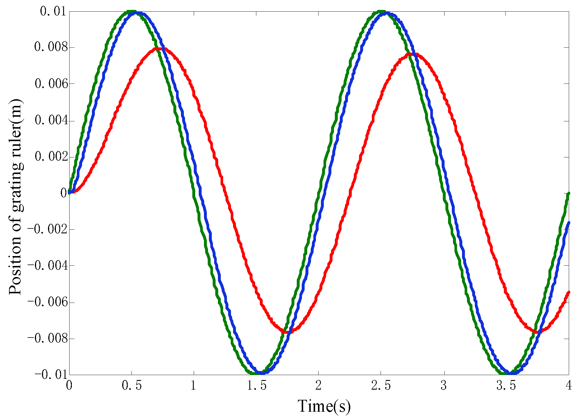
4. Validation of the Online HPGA Based Sliding Mode Control Strategy

In this section, the online HPGA-based sliding mode control is applied to the CPP system. Based on the system model described in Equation (8), a numerical simulation using Matlab is performed to validate the effectiveness of the proposed method. The method is also verified on the scale model of the CPP system, and the results indicate that the proposed method performed properly.

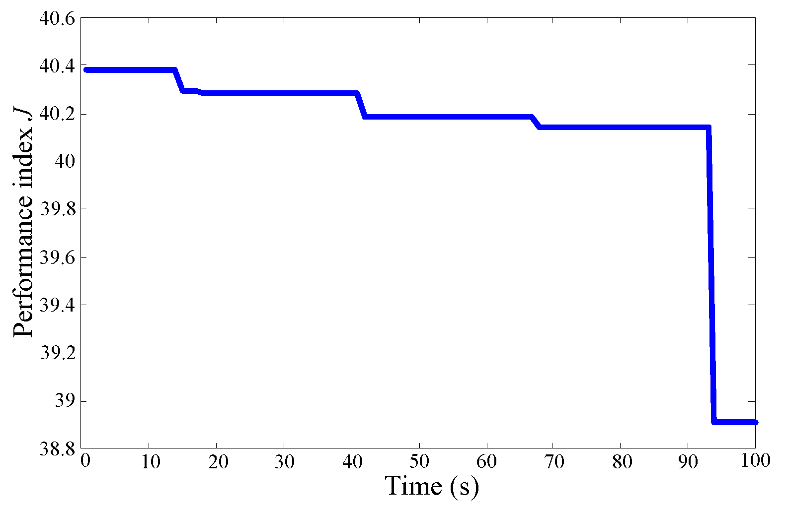
4.1. Numerical Simulation

In order to verify the effectiveness of the proposed method, PID controller is designed for contrast. The PID parameters are tuned according to Zigeler-Nichols oscillation method. The parameters in Equation (8) and the PID controller are shown in Table 2.
In the process of online HPGA, the number of initial samples is selected as m = 30, and the number of generations is selected as n = 100. According to Equation (14), α i ( i = 1 , 2 , , 4 ) in Equation (13) can be selected as α = [ 0.2 , 0.25 , 0.33 , 0.5 ] , and the initial values in vector c can be select as c = [ 90 , 60 , 120 , 17 ] . The optimization process is shown in Figure 6.
It is worth to note that the initialization of the model parameters is not critical, as the sliding mode control is insensitive to the inaccuracy of model parameters. As time goes on, the parameter estimator will rectify the parameters for the HPGA algorithm.
The CPP system is a typical angle-following system. Hence, sine signal tracking performance is compared between the proposed method and the traditional PID controller. In Figure 7, a sine signal input of 0.01 m is given to the CPP system. The blade angle is characterized by the position of the grating ruler. The lagging angle and maximum error are listed in Table 3. As it is observed, both control strategies result in an acceptable performance of the CCP system in the tracking of the desired sine signal.
During the voyage of a ship, the load fluctuation and the operation condition variations will result in model uncertainty. Hence, the sine signal tracking test based on the model with uncertainty is performed. In the simulation, a 20% load change was introduced into the system, and the uncertainties imposed in the model are listed as follows:
{ Δ α 1 = 0.05 α 1 Δ α 2 = 0.1 α 2 Δ α 3 = 0.1 α 3 Δ β = 0.32 β
According to Table 4 and Figure 8, the CPP system still has a good sine signal tracking performance by applying the online HPGA based sliding mode controller, whereas the PID controller no longer performs well with the model uncertainties.

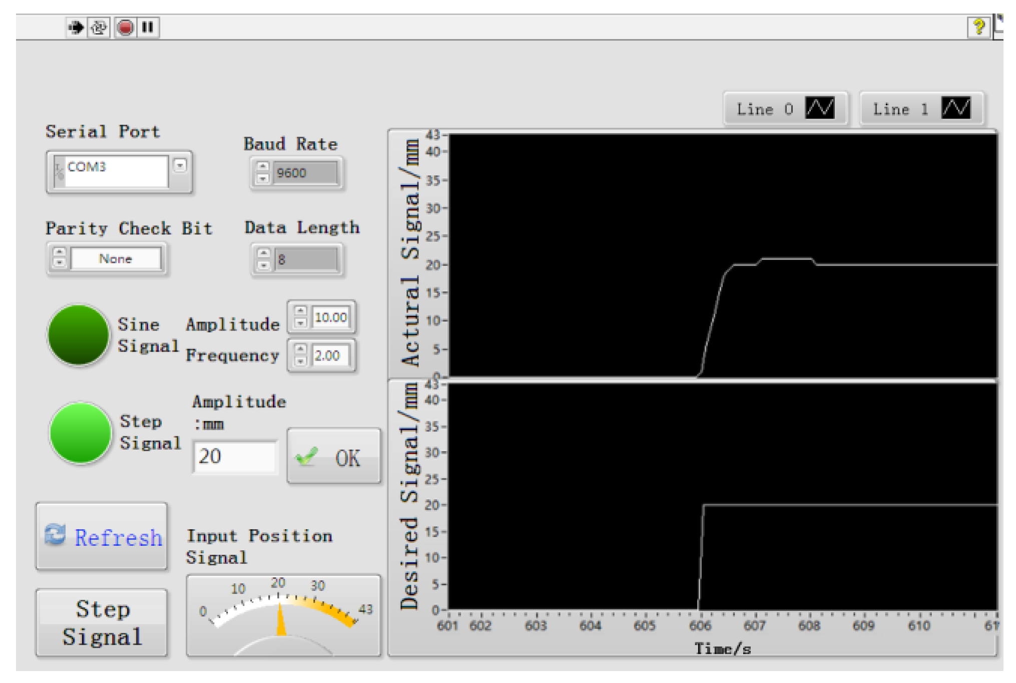
4.2. Numerical Simulation Experiment on the Scale Model of the CPP System

The real system structure is shown in Figure 9. Experiments about the tracking of the sine signal and step signal were performed on the scale model. The monitor is designed based on Labview, and the controller hardware circuit is mainly based on STM 32. The scheme of the scale model system is shown in Figure 10.
The results of the tracking of the desired position are shown in Figure 11 and Figure 12. In Figure 11, a step signal at 20 mm is given to the CPP system. It can be observed that the setting time is 0.4 s, and the overshoot is 5% without steady error. In Figure 12, a sine signal is given to the CPP system. The amplitude and frequency are 10 mm and 2 Hz, respectively. According to the result from Figure 12, the CPP system performed well in the tracking of desired sine signal and the lagging angle is 15.3°. Thus, we can conclude that the effectiveness of online HPGA-based sliding mode control is validated on the actual CPP system.

5. Conclusions

Stable and fast control of the CPP system is of great importance for the safe operation of the ship. In this paper, a chattering-free sliding mode control strategy optimized with online HPGA is proposed. In the presence of model uncertainties, the CPP system obtained desired regulation and tracking performance with the proposed method. The HPGA needs fewer parameters and shorter time for optimization than the traditional GA, which makes it possible to be applied in online optimization. The chattering-free sliding mode control can overcome the chattering phenomenon which appeared in the traditional sliding mode control and generates a smooth control output, which is important for the actuator. According to the simulation results from the numerical simulation and the scale model experiments, the online HPGA-based sliding mode control can lead to satisfactory performance for the CPP system.

Author Contributions

Methodology, Y.W.; software, H.F.; validation, Y.W. and Q.W.; formal analysis, Y.W.; writing—original draft preparation, Y.W.; writing—review and editing, Q.W. and H.F.; funding acquisition, Y.W. and H.F. All authors have read and agreed to the published version of the manuscript.

Funding

This work is supported by National Natural Science Foundation of China (51409062), the Fundamental Research Funds for the Central Universities (3072020CF0408).

Acknowledgments

Y.W. acknowledges the financial support from Chinese Scholarship Council (CSC) under grant 201706685010.

Conflicts of Interest

The authors declare no conflict of interest.

Nomenclature

CPPControllable Pitch Propeller
HPGAHigh Performance Genetic Algorithm
SMCSliding Mode Control
CF-SMCChattering-Free Sliding Mode Controller
PIDProportional-Integral-Derivative
RFNNRecurrent-Fuzzy-Neural-Network
GAGenetic Algorithm

References

  1. Martelli, M.; Figari, M.; Altosole, M.; Vignolo, S. Controllable pitch propeller actuating mechanism, modelling and simulation. J. Eng. Marit. Environ. 2014, 228, 29–43. [Google Scholar] [CrossRef]
  2. Xiong, Y.; Wang, Z.; Qi, W. Numerical study on the influence of boss cap fins on efficiency of controllable-pitch propeller. J. Mar. Sci. Appl. 2013, 12, 13–20. [Google Scholar] [CrossRef]
  3. Cohen, R.; Miculescu, D.; Reilley, K.; Pakmehr, M.; Feron, E. Online performance optimization of a DC motor driving a variable pitch propeller. J. Natl. Cancer Inst. 2013, 105, 14. [Google Scholar]
  4. Prats, M.A.M.; Carrasco, J.M.; Galvan, E.; Sanchez, J.A.; Franquelo, L.G.; Batlsta, C. Improving transition between power optimization and power limitation of variable speed, variable pitch wind turbines using fuzzy control techniques. In Proceedings of the Conference of the IEEE Industrial Electronics Society, Nagoya, Japan, 22–28 October 2000; pp. 1497–1502. [Google Scholar]
  5. Mirzaei, M.; Soltani, M.; Poulsen, N.K.; Niemann, H.H. An MPC approach to individual pitch control of wind turbines using uncertain LIDAR measurements. In Proceedings of the 2013 European Control Conference (ECC), Zürich, Switzerland, 17–19 July 2013; pp. 490–495. [Google Scholar]
  6. Balsamo, F.; De Luca, F. Continuous optimization of controllable pitch propeller for fast ferries. In Proceedings of the 9th HSMV Symposium on High Speed Marine Vechicles, Naples, Italy, 25–27 May 2011; p. 8. [Google Scholar]
  7. Dullens, F.P.M. Modeling and Control of a Controllable Pitch Propeller. Master’s Thesis, Technische University, Eindhoven, The Netherlands, 2009. [Google Scholar]
  8. Cazenave, T.; Pakmehr, M.; Feron, E. Peak-Seeking Control of a DC Motorhinolaryngology Driving a Variable Pitch Propeller. In Proceedings of the AIAA Guidance, Navigation, and Control Conference, Portland, OR, USA, 8–11 August 2011; p. 10. [Google Scholar]
  9. Biegel, B.; Juelsgaard, M.; Kraning, M.; Boyd, S.; Stoustrup, J. Wind turbine pitch optimization. In Proceedings of the International Conference on Control Applications (CCA), Denver, CO, USA, 28–30 September 2011; pp. 1327–1334. [Google Scholar]
  10. Muljadi, E.; Butterfield, C.P. Pitch-controlled variablespeed wind turbine generation. IEEE Trans. Ind. Appl. 2001, 37, 240–246. [Google Scholar] [CrossRef] [Green Version]
  11. Fridman, L. Sliding mode enforcement after 1990: Main results and some open problems. In Sliding Modes after the First Decade of the 21st Century; Springer: Berlin/Heidelberg, Germany, 2011; pp. 3–57. [Google Scholar]
  12. Meng, Z.; Ren, W.; You, Z. Distributed finite-time attitude containment control for multiple rigid bodies. Automatica 2010, 46, 2092–2099. [Google Scholar] [CrossRef]
  13. Liu, S.; Zhao, S.; Wang, Y. Smooth Sliding Mode Control and Its Application in Ship Boiler Drum Water Level. Math. Probl. Eng. 2016, 2016, 1–7. [Google Scholar] [CrossRef] [Green Version]
  14. Mien, V.; Kang, H.J.; Shin, K.S. Adaptive fuzzy quasi-continuous high-order sliding mode controller for output feedback tracking control of robot manipulators. J. Mech. Eng. Sci. 2014, 228, 90–107. [Google Scholar] [CrossRef]
  15. Cao, L.; Chen, X. Input-output linearization minimum sliding mode error feedback control for spacecraft formation with large perturbations. J. Aerosp. Eng. 2015, 229, 352–368. [Google Scholar] [CrossRef]
  16. Jin, L.; Liu, Y. Study on adaptive slid mode controller for improving handling stability of motorized electric vehicles. Math. Probl. Eng. 2014, 2014, 10. [Google Scholar] [CrossRef]
  17. Wai, R.J. Sliding-mode controller for PM synchronous servo motor drive using recurrent fuzzy neural network. IEEE Trans. Ind. Electron. 2001, 48, 926–944. [Google Scholar]
  18. Utki, V.I. Sliding Modes in Control and Optimization; Springer: Berlin/Heidelberg, Germany, 1992. [Google Scholar]
  19. Bartolini, G.; Ferrara, A.; Usai, E. Chattering avoidance by second-order sliding-mode control. IEEE Trans. Autom. Control 1998, 43, 241–246. [Google Scholar] [CrossRef]
  20. Levant, A. Robust exact differentiation via sliding mode technique. Automatica 1998, 34, 379–384. [Google Scholar] [CrossRef]
  21. Levant, A. Universal SISO sliding-mode controllers with finite-time convergence. IEEE Trans. Autom. Control 2001, 46, 1447–1451. [Google Scholar] [CrossRef] [Green Version]
  22. Levant, A. Homogeneity approach to high-order sliding mode design. Automatica 2005, 41, 823–830. [Google Scholar] [CrossRef]
  23. Levant, A. Principles of 2-sliding mode design. Automatica 2007, 43, 576–586. [Google Scholar] [CrossRef] [Green Version]
  24. Shtessel, Y.B.; Shkolnikov, I.A.; Brown, M.D. An asymptotic second order smooth sliding mode control. Asian J. Control 2003, 5, 498–504. [Google Scholar] [CrossRef]
  25. Du, H.; Yu, X.; Chen, M.Z.Q.; Li, S. Chattering-free discrete-time sliding mode control. Automatica 2016, 68, 87–91. [Google Scholar] [CrossRef]
  26. Feng, Y.; Han, F.; Yu, X. Chattering free full-order sliding-mode control. Automatica 2014, 50, 1310–1314. [Google Scholar] [CrossRef]
  27. Gong, M.; Wang, S.; Liu, W.; Yan, J.; Jiao, L. Evolutionary computation in China: A literature survey. CAAI Trans. Intell. Technol. 2016, 1, 334–354. [Google Scholar] [CrossRef]
  28. Lu, J.; Chen, Z.; Yang, Y.; Lv, M. Online Estimation of State of Power for Lithium-Ion Batteries in Electric Vehicles Using Genetic Algorithm. IEEE Access 2018, 6, 20868–20880. [Google Scholar] [CrossRef]
  29. Mehrafsa, A.; Sokhandan, A.; Karimian, G. A high performance genetic algorithm using bacterial conjugation operator (HPGA). Genet. Program. Evolvable Mach. 2013, 14, 395–427. [Google Scholar] [CrossRef]
  30. Huang, S.C.; Jiau, M.K.; Lin, C.H. Optimization of the carpool service problem via a fuzzy controlled genetic algorithm. IEEE Trans. Fuzzy Syst. 2015, 23, 1698–1712. [Google Scholar] [CrossRef]
  31. Li, G.; Jiang, H.; He, T. A genetic algorithm based decomposition approach to solve an integrated equipment-workforce-service planning problem. Omega 2015, 50, 1–7. [Google Scholar] [CrossRef]
  32. Iwankowicz, R.R. An efficient evolutionary method of assembly sequence planning industry. Assem. Autom. 2016, 36, 60–71. [Google Scholar] [CrossRef]
  33. Chakraborty, S. Controllable Pitch Propeller (CPP) vs. Fixed Pitch Propeller (FPP). Available online: https://www.marineinsight.com/naval-architecture/controllable-pitch-propeller-cpp-vs-fixed-pitch-propeller-fpp/ (accessed on 24 June 2020).
  34. Servo Valve Operation Manual, Shanghai Hengtuo Hydraulic Control Technology Co. LTD. Available online: http://www.htservo.com.cn/filedownload/59272 (accessed on 24 June 2020).
  35. Zhao, R.; Liao, D.; Liu, B. Simulation on work roll bending control system of cold rolling mill. J. Univ. Sci. Technol. Liaoning 2014, 9, 33–38. [Google Scholar]
Figure 1. The actual CPP system (left) and its scale model (right).
Processes 08 00953 g001
Figure 2. Motion relationships of the main equipment in the CPP system.
Processes 08 00953 g002
Figure 3. Block diagram of the CPP control system.
Processes 08 00953 g003
Figure 4. Frequency response of CSDY-I type jet pipe electro-hydraulic servo valve.
Processes 08 00953 g004
Figure 5. The theory of the online HPGA-based sliding mode control for the CPP system.
Processes 08 00953 g005
Figure 6. The optimal process of performance index J.
Processes 08 00953 g006
Figure 7. Variation of the grating ruler position (the proposed method in the blue line, PID controller in the red line, and the desired sine signal in the green line).
Processes 08 00953 g007
Figure 8. Variation of the grating ruler position (the proposed method in the blue line, PID controller in the red line, and the desired sine signal in the green line).
Processes 08 00953 g008
Figure 9. System structure of the scale model.
Processes 08 00953 g009
Figure 10. Scheme of the scale model of the CPP system.
Processes 08 00953 g010
Figure 11. Time response of the hydraulic cylinder position in the tracking of the desired step signal.
Processes 08 00953 g011
Figure 12. Time response of the hydraulic cylinder position in the tracking of the desired sine signal.
Processes 08 00953 g012
Table 1. Parameters for the hydraulic cylinder.
SymbolMeaningValue
DInternal diameter28 mm
dDiameter of piston rod16 mm
AEffective area of piston1.13 × 10−4 m2
lStroke of the piston43 mm
VtThe total capacity of the oil chamber7.91 × 10−5 m3
mMass of the hydraulic cylinder22 Kg
QinTotal oil flow into the control chamberL/min
QoutTotal oil flow out of the control chamberL/min
βeElastic modulus of liquid70 MPa
pPressure of the oil in the control chamberMpa
CtcTotal leakage coefficient of hydraulic cylinder0.2 mL/(min·MPa)
BcViscous damping coefficient between piston and load500 N/(m/s)
KSpring stiffness of the propellerN/m
FExternal force acting on the pistonN
Table 2. Parameters in the model and PID controller.
ParameterValueParameterValue
α11α33.45 × 10⁻⁵
α22.353*10−3β0.2956
Kp10.8Ti1
Td0.25
Table 3. Performance of the proposed method and PID controller.
Control StrategyLagging AngleMaxmum Error
Online HPGA based
sliding mode controller
0.8 mm
PID controller15°2 mm
Table 4. Performance of the proposed method and PID controller with model uncertainties.
Control StrategyLagging AngleMaxmum Error
Online HPGA based
sliding mode controller
10.4°0.3 mm
PID controller45.7°5.6 mm

