1. Introduction
Fibre-reinforced composites (FRCs), popularly known for being lightweight and having extraordinary mechanical properties, include carbon fibre-reinforced composites (CFRCs) and glass fibre-reinforced composites (GFRCs) [
1,
2,
3,
4]. They have an advantageous low weight to strength ratio; however, the fibres are expensive [
1,
3]. The presence of such valuable carbon fibres (CFs) and glass fibres (GFs) makes their accumulated FRC wastes into marketable raw materials. After decades of employing them in high-performance applications, industrial progress towards recycling such enormous wastes has opened up new, affordable disposal methods [
1].
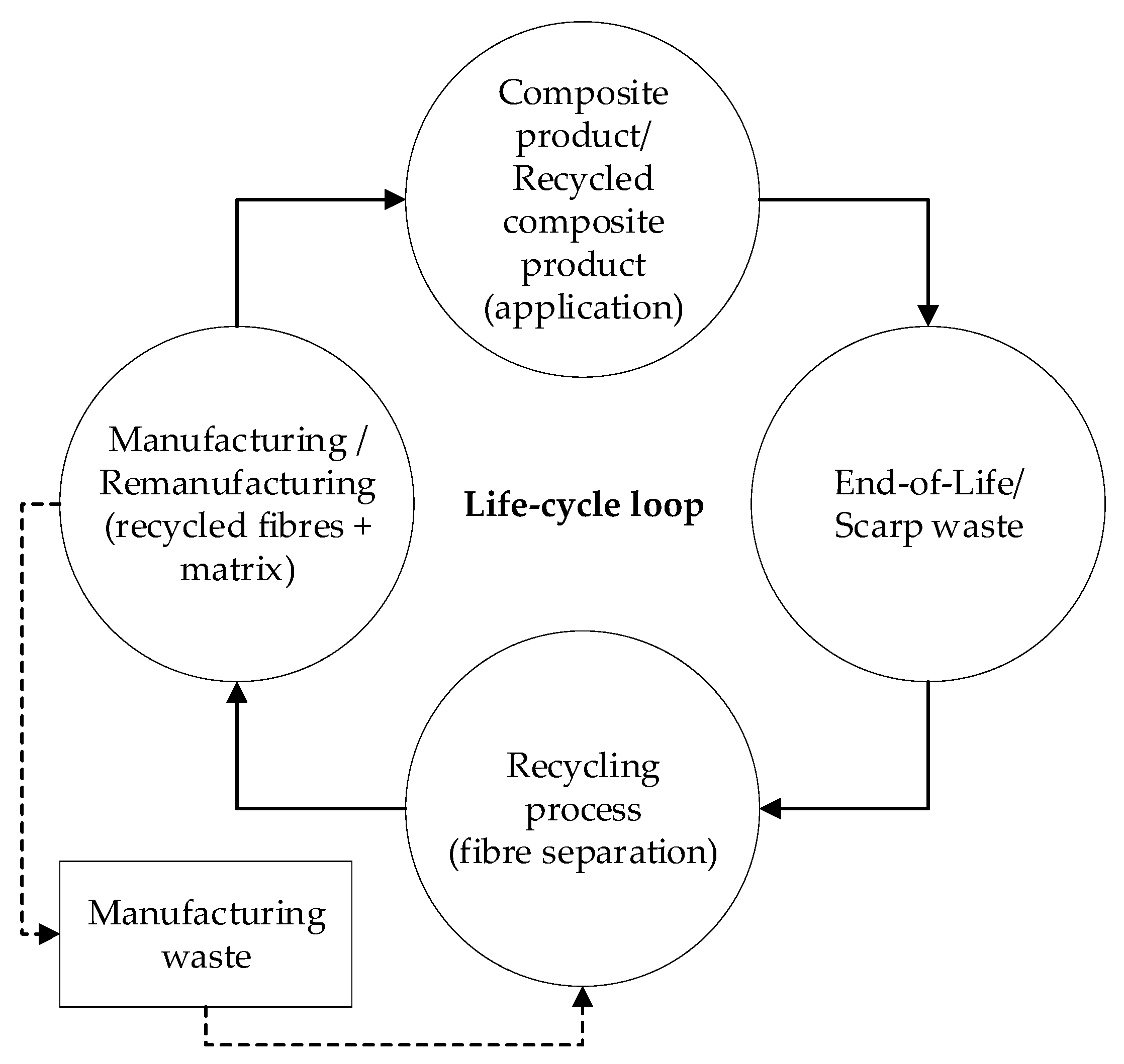
In the current scenario, achieving the closed-loop recycling (CLR) [
5,
6,
7,
8] approach is a primary target for recycling industries, leading to significant attention from researchers globally. Typically, for CLR, the valuable fibres from the composite wastes are reclaimed, remanufactured, and reused within a closed-loop (see
Figure 1), promoting the circular economy [
6]. In the past two decades, various studies [
1,
2,
3,
4], [
9] have widely explored the recycling techniques that can be used to effectively recover fibres (CF and GF) from different waste sources, so that they can be reused into new composites. Modern studies are working on improving the mechanical properties of the recycled composites, on matching those of their virgin form [
1].
Within the enormous quantity of CFRC and GFRC wastes being produced, manufacturing-based waste contributes 40%, among which 60% of the wastes are trimmings and off-cuts [
2]. Such wastes (pre-consumer waste) are challenging to recycle due to their irregular profile, dimension, fibre distribution, orientation, matrix phase, and volume. To successfully close their life-cycle loop, it is better to recycle long, continuous, and aligned fibres, so that later they can be recycled a further n-number of times. The thermal recycling process (pyrolysis) appears to be suitable for recycling manufacturing waste. In a typical thermal recycling process, the matrix phase evaporates from the reinforced fibres (core material) because of its higher calorific value [
2,
3,
9,
10]. However, this results in recovering discontinuous, short and randomly oriented fibres. Additionally, selecting a single favourable process to recycle both CFRC and GFRC wastes appears to be complicated.
This study attempts to recycle both types of fibres (CF and GF), utilising a single process. A novel thermal recycling approach is used which adopts incineration and combustion principles in a controlled environment. The process employs an open chamber heat radiation in a batch reactor. The recycled carbon fibres (rCFs) and recycled glass fibres (rGFs) are reused into recycled carbon fibre-reinforced epoxy (rCF/EP) composites and recycled glass fibre-reinforced epoxy (rGF/EP) composites. Furthermore, the new composites are investigated to study their mechanical properties. Overall, this study aims to achieve a CLR approach to recycle CFRC and GFRC manufacturing wastes, recover CF and GF fibres, remanufacture rCF and rGF fibres, and examine their mechanical properties.
2. Materials and Methods
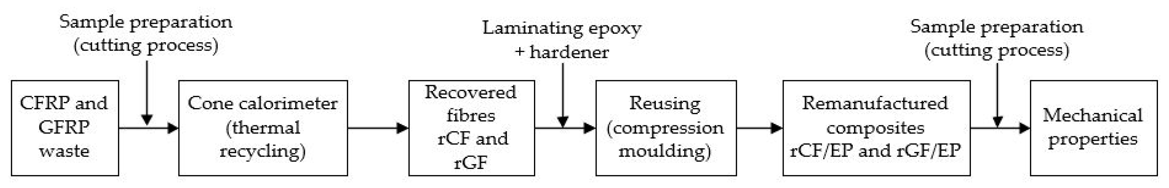
This study adopts a two-stage CLR approach. The initial stage consists of thermal recycling, focusing on fibre recovery from the composite wastes. The second stage involves remanufacturing of the recovered fibres into new composites. In addition to this approach, the study primarily focuses on characterising the newly produced composites using standard test procedures to measure their tensile and impact properties. All three methods are briefly outlined in this section. The methodology used in this study is shown in
Figure 2.
2.1. Fibre Recovery
2.1.1. Materials
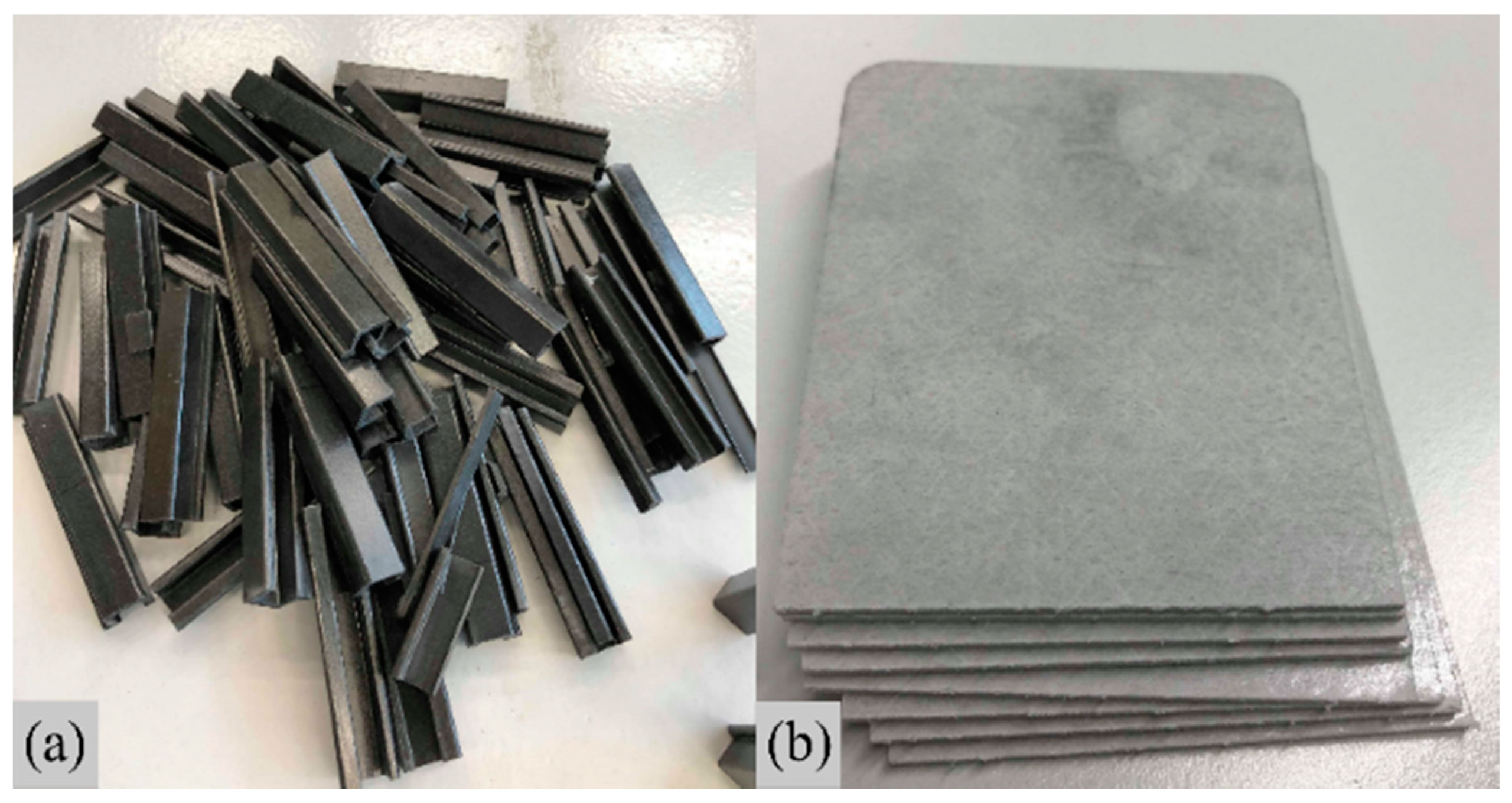
The materials used in this research work were pre-consumer wastes (discarded materials). These consisted of trimmings and off-cuts from commercially available carbon fibre-reinforced epoxy composite (CFEC) and glass fibre-reinforced polyester composite (GFPC) and were generously provided by Exel Composite Oyj, Finland (
Figure 3). Both composites had a distinctive profile and fibre orientation. The CFECs possessed a C-shaped profile with a density of 1.81 g/cm
3. They featured a unidirectional (UD) fibre orientation (0°) with 55.5 wt% virgin carbon fibres (vCFs) (type unknown) and 44.5 wt% epoxy resin matrix. On the other hand, the GFPCs were rectangular plates with thicknesses ranging between 1.60 and 2.30 mm. They had a profile density of 1.52 g/cm
3 and featured a laminated thin-ply profile with UD (90°) fibre oriented virgin glass fibres (vGFs) in the middle enclosed by randomly oriented (chopped strand mat) vGFs on both sides. The composite contained 44 wt% vGFs (E-glass) reinforced with 56 wt% polyester as the matrix. Apart from the properties mentioned above, other properties were unknown.
2.1.2. Process Setup
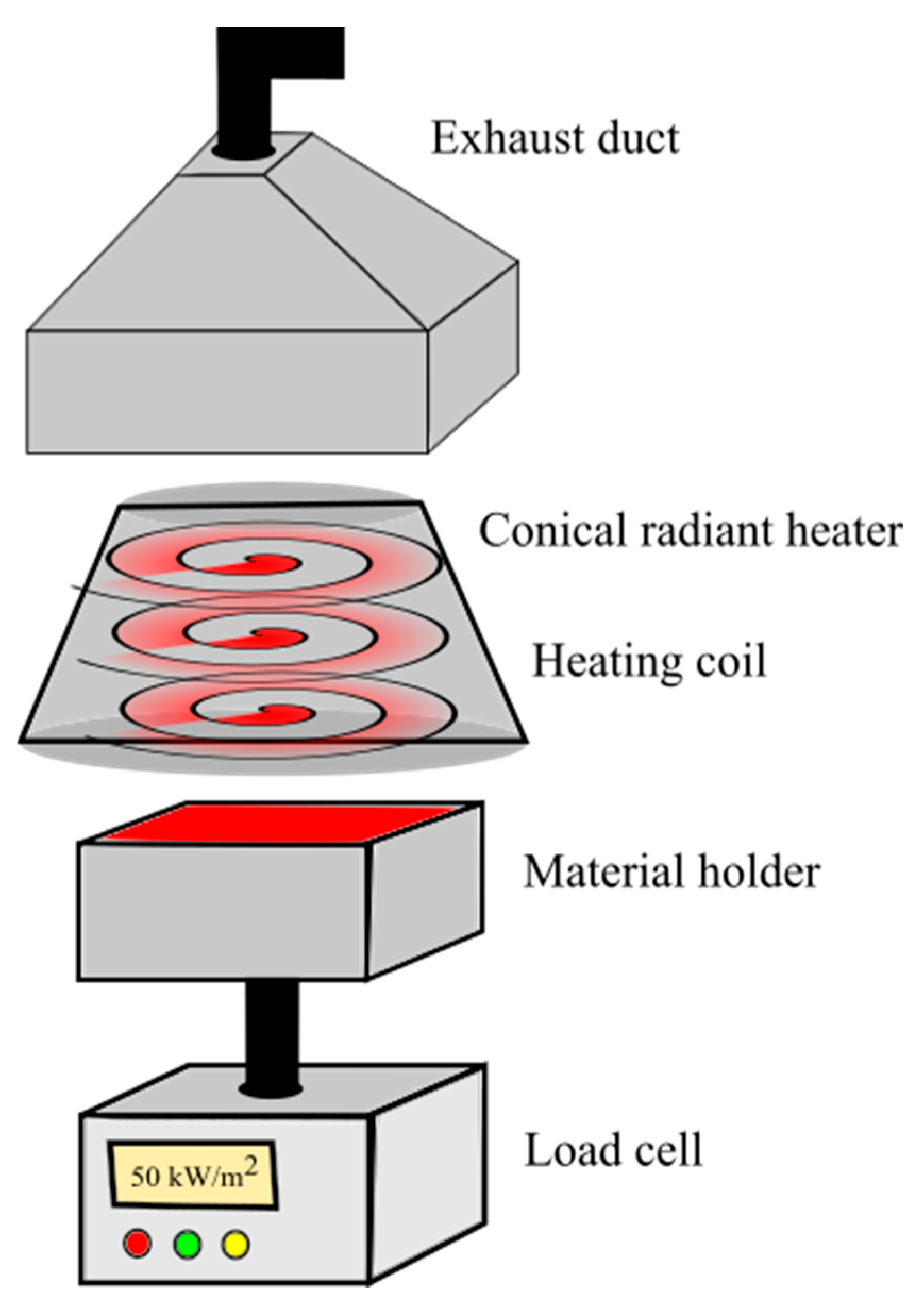
A cone calorimeter (CC) setup was utilised for recycling the waste composites.
Figure 4 presents a schematic arrangement of the CC. The setup consists of a load cell to measure the mass change, a material holder, a conical radiant heater with a heating coil to generate heat flux, and an exhaust duct to remove smoke throughout the process.
The recycling process was performed in batches, separately for CFEC and GFPC. Both the composite wastes were prepared to fit the material holder’s (refractory) internal dimensions—110 (l) × 110 (b) × 10–20 (h) mm. A series of experiments were trialed before finalising the isothermal process condition. The temperature for cured epoxy to fully evaporate was in the range 450–600 °C [
11,
12], and for thermoset polyester, it was in the range 400–700 °C [
11]. The optimal temperature for both the materials was fixed based on the processing time. Apparently, the temperature and process duration were inversely proportional to each other. Therefore, various possibilities were trialed with temperature and time ranges of 550–800 °C and 45–15 min, respectively.
The processing time was calculated between times of inserting and removing the material holder into the heat flux region. Once the materials were introduced to the heat flux chamber, the change in mass over time was recorded in the load cell placed beneath the material holder (as shown in
Figure 4). Based on trial experiments, the heat radiation was kept constant at 50 kW/m
2 for both the composites, throughout the actual recycling process. However, the operating period varied for CFECs and GFPCs, depending on their mass.
During the recycling, smoke appeared from the material holder, indicating the start of the process, followed by high flaming. After a noticeable period, the flame extinguished gradually, indicating the end of the process. The generated heat flux at 50 kW/m2 was equivalent to 750 °C, however, this was the coil’s surface temperature. The monitored isothermal surface temperature on the composite wastes was 550 °C. At this temperature and atmospheric pressure, the matrix phase evaporated entirely, leaving the fibres in the material holder. The respective mass change over time was recorded using ConeCalc software. The recycled fibres (rFs) were carefully removed from the material holder and prepared for the remanufacturing stage.
2.2. Remanufacturing
2.2.1. Fibre Alignment
The existing composite structure in the waste CFECs was unidirectionally aligned non-woven CFs. The recycling process only removed the epoxy matrix phase, without interrupting the fibres’ UD arrangement. Similarly, in the case of GFPCs, heat removed the polyester matrix phase, leaving the GFs. The rGFs consisted of 60 wt% unidirectionally aligned non-woven fibres, and 40 wt% randomly oriented fibres, which were manually aligned later. Highly aligned and continuous fibres mean the composite is capable of possessing a higher fibre volume fraction, of up to 60 wt% [
11]. Continuous fibres mean the fibres are extended from one end of the sample to the other end without any discontinuity in the fibre system [
13]. The rFs of both the rCF and the rGF possessed an average fibre length of 100–110 mm. They were continuously aligned and unidirectionally oriented (0°), meaning that they were ready to be reused.
2.2.2. Composite Production
Table 1 presents information about the different types of composites which were designed to be manufactured. The designed composites consisted of two primary composites (PCs) and one secondary composite (SC). The first PC was manufactured utilising rCF reinforced with an epoxy matrix (rCF/EP) and the second PC utilised rGF reinforced with an epoxy matrix (rGF/EP). Furthermore, both the PCs were manufactured using two recipes (as seen in
Table 1), based on their fibre volume (V
f) and resin volume (V
r). The SC was manufactured with pure epoxy resin (P-EP), with no fibres, to evaluate the remanufacturing process.
The compression moulding (CM) technique was adopted to remanufacture the designed composites. Both rCFs and rGFs were reused by reinforcing them with a new epoxy resin system. Commercially available laminating epoxy + hardener (EP) with a combined density of 1.5 g/cm3 was used in a 2:1 resin to hardener ratio. The EP system was easy to handle, with an operating time of up to 20 min and 8 h of curing time at room temperature.
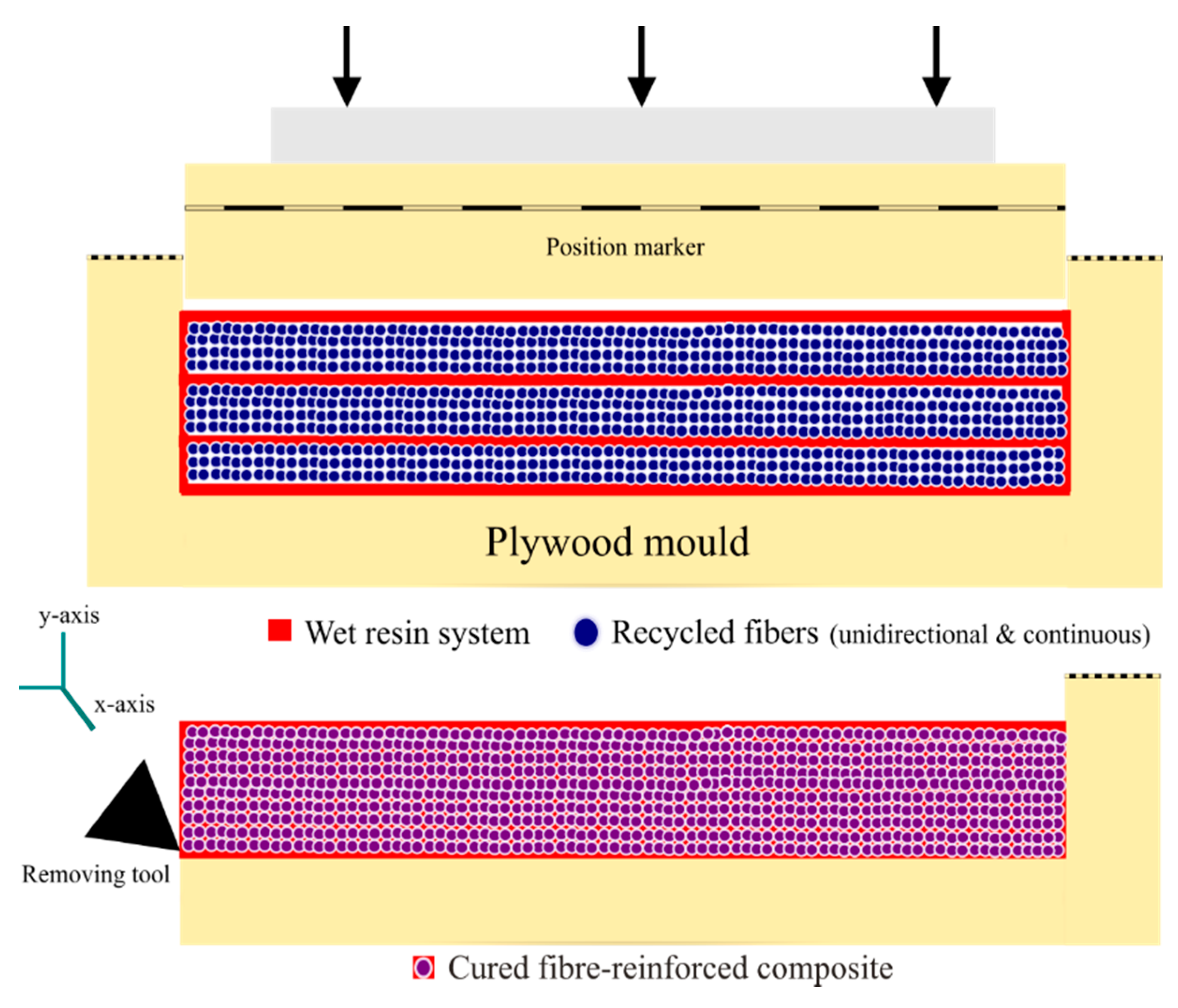
A dismantlable plywood mould was custom-made to manufacture the designed composites. To maintain uniformity, the inner dimensions of the plywood mould (110 × 110 × 10 mm) were similar to those of the material holder dimension from the CC. The inner-surfaces of the mould were waxed (3–5 wax layers) for the compression moulded composites (CMCs) to be able to slip easily. The hand layout method was adapted to align the rF bundles layer-by-layer (LBL), with EP manually poured between each layer (
Figure 5).
Figure 5 presents the LBL CM arrangement of the recycled fibres and epoxy system. Higher fibre volume fractions required higher moulding pressure. However, aligned and continuous fibres demanded < 1 MPa moulding pressure [
11]. Therefore, the CM pressure was calculated based on the mould position. The composites were designed to be manufactured into 110 × 110 × 10 mm dimensions. Therefore, respective positions, based on volume, were pre-marked on the plywood mould (seen in
Figure 5). The density–volume relation was used to calculate the mass of the designed composites. The compression was applied until the position markers aligned into a straight line, and the pressure was maintained until the composites cured entirely. The CMCs was cured at room temperature for 24 h. Overall, five composites for each recipe (25 composites in total) were produced, and their average densities were measured (see
Table 1).
2.3. Composite Characterisation
The compression moulded square samples were thoroughly cleaned using a dry cloth to eliminate minor wax residue from their exterior surface. They were further dried at +23 °C and 50% relative humidity (RH) for 24 h, before being subjected to further tests. ISO standard procedures were adopted to prepare the test samples.
2.3.1. Tensile Strength
ISO 527-2 [
14] was followed to measure the tensile strength (TS) and young modulus (YM) of the CMCs. The samples were prepared according to small specimens, type 1BA. Initially, utilising an electric circular saw system with water as a coolant, rectangular outer profiles were made. Later, dogbone shaped patterns were precisely cut using an automatic cutting machine. A minimum of 15 samples for each composite recipe (overall five types, as seen in
Table 1) were prepared and subjected to a 24 h rest period at +23 °C and 50% RH before the actual testing. The experiments were performed using a Zwick Roell (Z020) tester at a test speed of 2 mm/min. With the guidance of an extensometer, the experimental data were collected and processed automatically using testXpert II software.
2.3.2. Impact Strength
ISO 179-1 [
15] was followed to measure the impact strength (IS) of the CMCs. The samples were prepared according to type 1 test specimens—80 ± 2(l) × 10 ± 0.2(b) × 4 ± 0.2(h) mm—under charpy unnotched impact strength, utilising an electric circular saw system with water as a coolant. A minimum of 15 samples for each type of composite were prepared and subjected to a 24 h rest period at +23 °C and 50% RH before the actual testing. The impact energy observed in breaking or in some cases damaging the samples was measured in kJ/m
2. The experiments were performed using a pendulum impact tester with a hammer size of 40 Kpcm for rCF/EP composites and 10/20 Kpcm for rGF/EP and P-EP composites.
2.3.3. Microscopy
The rFs (both rCF and rGF) and recycled FRCs (both rCF/EP and rGF/EP) were examined employing scanning electron microscopy (SEM) to investigate their morphologies. The examination was conducted using a Jeol JSM-5800 LV scanning microscope at various magnification. The selected materials were prepared and dried in a vacuum chamber for 24 h before testing. The fibre diameters (Φf) were measured at 4k magnification. The images of fibre alignment and tensile pull-outs were captured at 500, 1k, 2k and 3k magnification.
3. Results and Discussion
3.1. Thermal Recycling Approach
3.1.1. Process Outcome
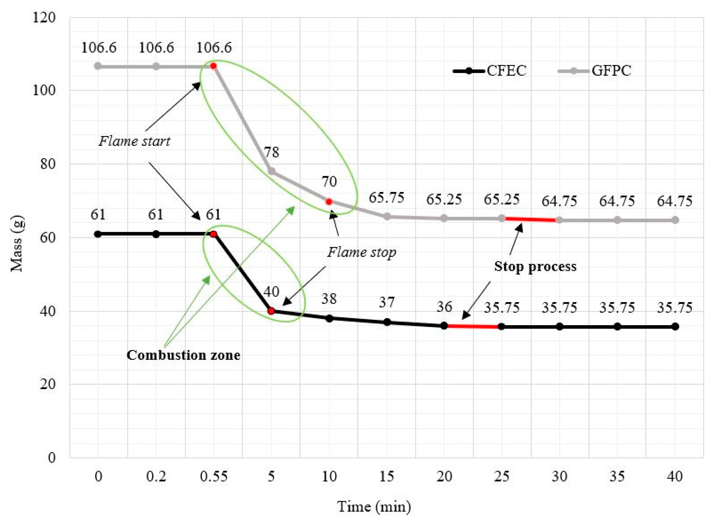
Figure 6 presents the data collected during the isothermal process, analysing the relationship between mass stagnant (g) and time (min). As observed, smoking started immediately after introducing the composites to the heat radiation. Without any externally induced sparking, flames appeared subsequently, indicating the start of the combustion process within the material holder. During the process, the matrix phase for both the composite wastes (CFEC and GFPC) rapidly oxidised and evaporated in 5–10 min, followed by the flame turning-off, indicating the end of combustion. This process was marked as the combustion zone (CZ,
Figure 6), and left the fibres untouched in the material holder. The smoke started initially after 15–20 s for CFECs and 10–15 s for GFPCs. For both the materials, flames started and stopped inside the marked CZ in which the entire recycling process took place. The overall process was terminated once the mass change became stagnant. The processing time to recycle CFECs was 20–25 min, and for GFPCs it was 25–30 min.
In a typical thermal recycling process, CF cannot be oxidised at temperatures <600 °C [
16]. However, they become sensitive at higher temperatures >600 °C in the presence of air, making it easy to eliminate the resin phase from the reinforced-fibres rapidly, in a short period [
17]. In GF recycling, temperatures >650 °C result in a massive drop in the mechanical properties of the rFs [
18]. In this process, even though the generated heat flux at 50 kW/m
2 was equivalent to 750 °C, the monitored heat on the surface of the composite wastes during recycling was 550 °C. At this optimal temperature, the recycling process was rapid for both fibre types, and the maximum amount of fibres were able to be recovered, without any significant losses. Overall, this approach successfully combusted both the thermoset (epoxy and polyester) matrixes from the received manufacturing wastes.
3.1.2. Fibre Yield
Unlike typical thermal recycling processes, this process is capable of recycling bulk quantities. For a single batch, 35 ± 2 g (final mass) rCFs was obtained from 60 ± 2 g (initial mass) of CFEC wastes, and 65 ± 2 g (final mass) rGFs was obtained from 105 ± 2 g (initial mass) of GFPC wastes. The overall recovery rate of the process was 95–98% CFs recovered with 2–5% residue (negotiable) and 80–82% GFs recovered with 16–18% residue (char formation) + 2% ash (top surface).
The recycling process utilised in this study to thermally disintegrate the matrix possesses similar interpretations to the frequently used thermogravimetric analysis (TGA) approach. However, this process produces a higher yield. Additionally, the process can be up-scaled to any specific degree without limitations. By just increasing the area of the heating coil, recycling of longer and more intricate shapes can be achieved, without disturbing their structural integrity.
3.1.3. Fibre Evaluation
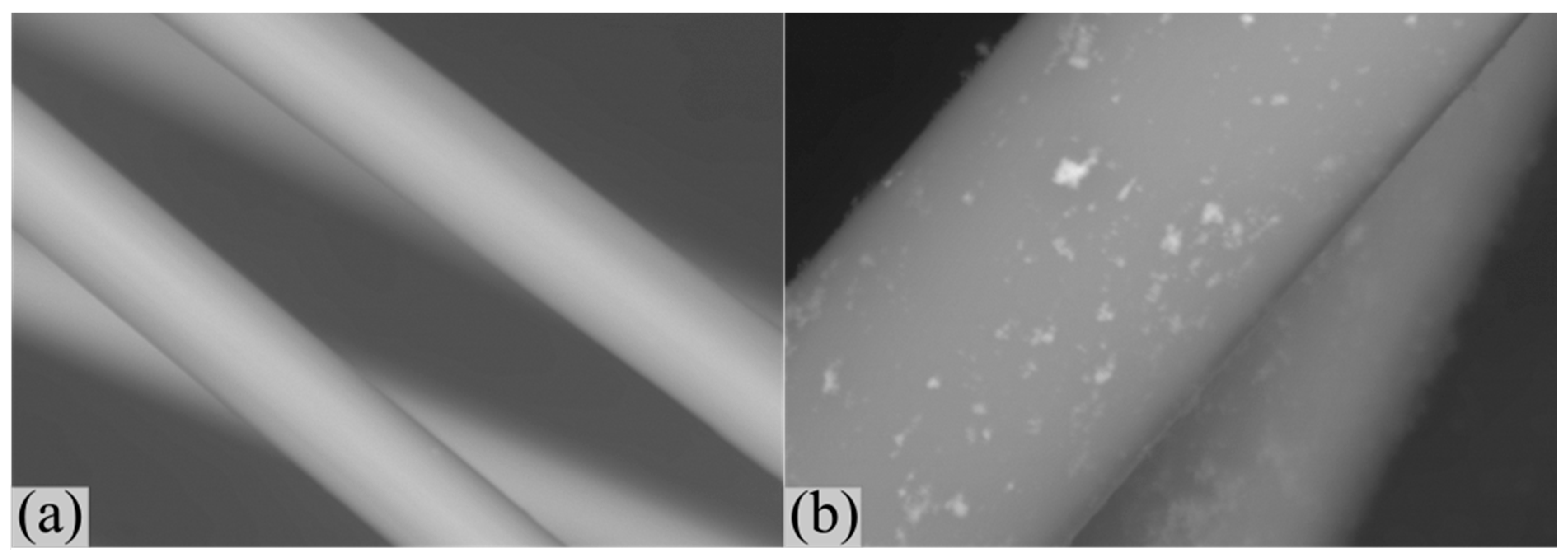
Figure 7 presents the SEM image of the rFs. The rCFs showed no evidence of any presence of residues (
Figure 7a). The epoxy resin tends to leave no residue behind after the thermal process [
11]. In addition, the higher surface purity results in better impregnation with new epoxy resin [
19]. The average measured diameter (
Φf) of the rCFs was 6.5 ± 0.2 µm. Apart from the SEM examination, the fibres visually looked fluffy and difficult to handle (realign).
Unlike rCFs, rGFs had evidence of impurities, including resin residues and minor char deposits on the fibre surface (
Figure 7b). As mentioned previously, 18–16% of the rGFs contained residue from the recycling process. The average measured diameter (
Φf) of the rGFs was 20.5 ± 0.25 µm. The handling of the fibres appeared to be easier compared to rCFs.
3.2. Mechanical Properties
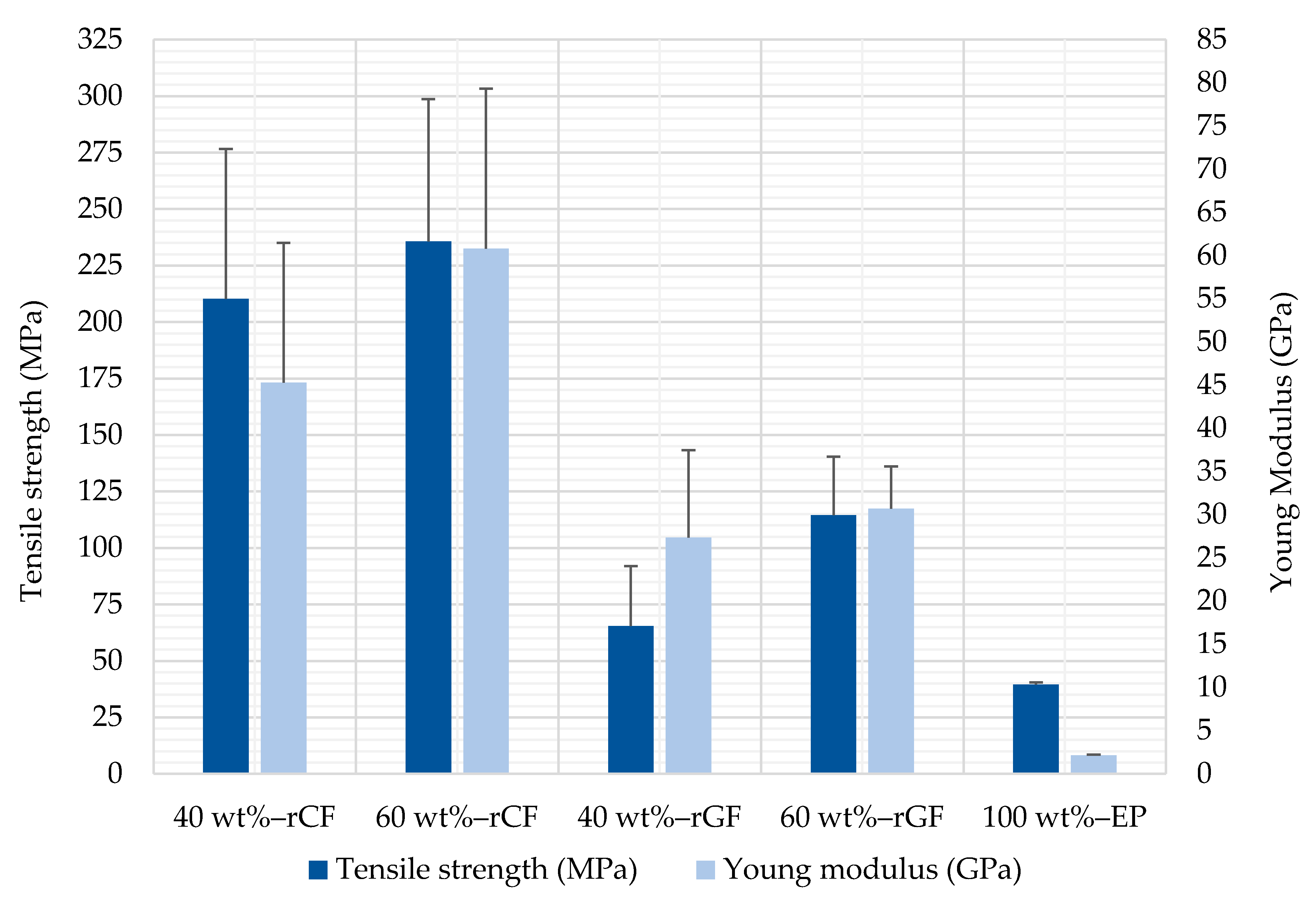
Table 2 presents the results of the mechanical properties of the CMCs. An increase of ≈20 wt% fibre volume positively increased the mechanical properties of both the rCF/EP: TS (12%), YM (34.27%) and IS (7.26%) and the rGF/EP: TS (75.14%), YM (12.23%) and IS (116.16%) composites.
3.2.1. Tensile Properties
Figure 8 presents the measured average values of the TS and YM. The error bars display the calculated standard deviation for each composite type, and the obtained stress–strain curves appeared to be linear. The YM of all the tested FRCs exhibited a higher value range than their associated TS (seen in
Table 2). The reason for this outcome is due to the absence of fibre discontinuity in the composites. The aligned continuous fibres increased their elastic region, resulting in stiffer composites.
In rCF/EP composites, the increase in fibre volume (≈20 wt%) increased the YM, making the composites extra stiff, with a minor increase in the TS. During the tests, most of the rCF/EP composite samples failed in their midsection. However, a couple of cases exhibited cracking parallel to the tensile direction. With further investigation, an absence of a resin system was identified across the fibre bundles, causing the layers to slip with a minimal applied load. Such poorly wet fibres appeared fluffy, and can be related to a low electrostatic attraction between individual fibres. Two samples were excluded for exhibiting low wettability. Both the rCF/EP type composites (40 and 60 wt%) displayed fibre-dominated failure [
20], confirming the failures occurred in the interface between the fibre and epoxy system. Overall, the rCF/EP composites were notably durable compared to the rest of the composites, without much variation in testing behaviour between the composite types.
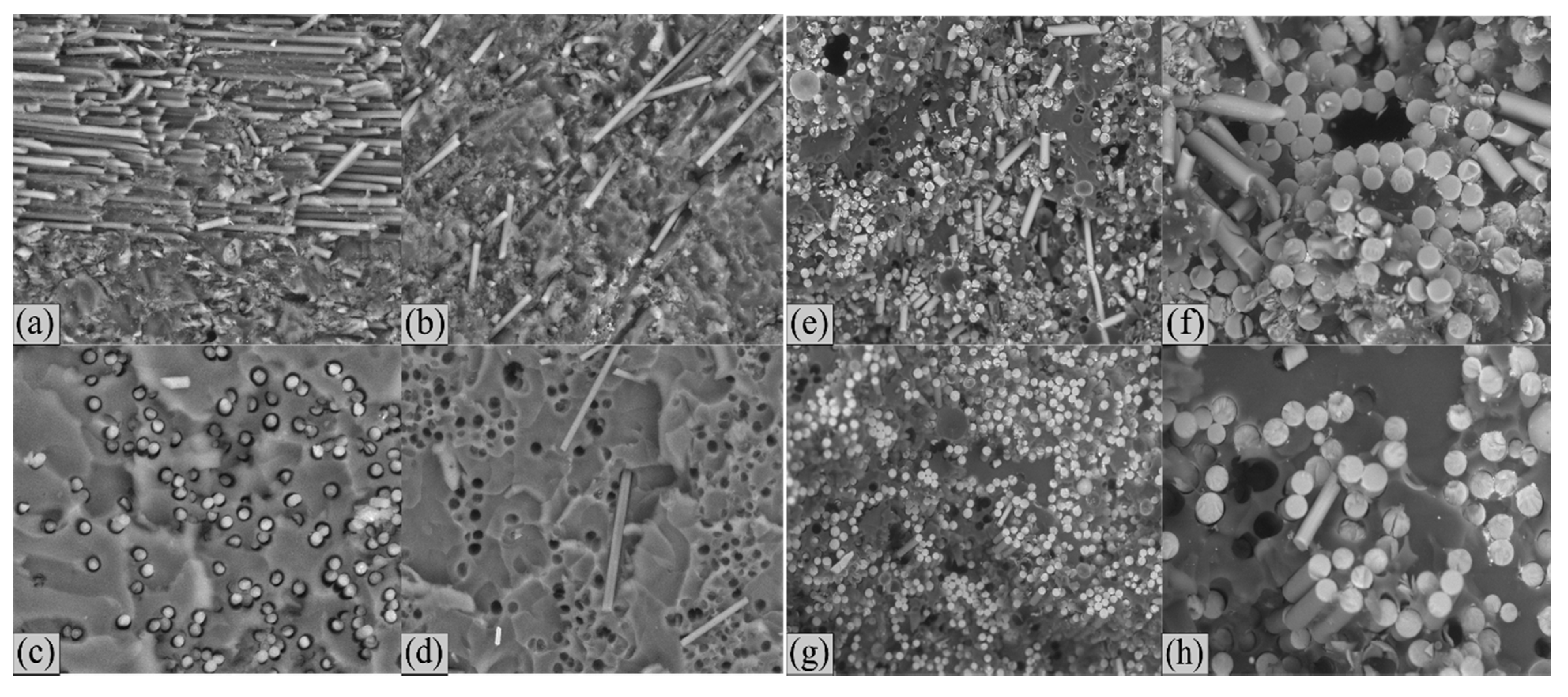
In rGF/EP composites, the increase in fibre volume (≈20 wt%) essentially doubled the TS of the composites, with a negligible change to the YM. During the tests, all the samples failed in their midsection perpendicular to the direction of the tensile force, with no evidence for poorly wetted rGFs. The applied heat increased the rGF density, resulting in a much stiffer fibre and reduced ductility [
21]. Both the rGF/EP type composites (40 and 60 wt%) displayed a highly brittle nature and resulted in brittle failure. Crack propagations were observed in both the fibre and matrix cross-sections. In addition, the tested samples showed multiple microbreaks and individual broken fibres distributed in various spots (
Figure 9h).
Figure 9 presents the SEM images of the tensile tested samples. Both rCF/EP and rGF/EP composites show evidence for defibrillation [
22] and pull-out type failure. The rCF/EP composite sample pull-outs, associated with 60 wt% (
Figure 9c,d) appear evenly distributed, with a dense fibre arrangement compared to the 40 wt% (
Figure 9a,b) samples. Compared to rCF/EP composites, rGF/EP composites appeared to be extra brittle, with a three times higher fibre diameter and stable fibre-matrix interface (
Figure 9e–h).
The P-EP composites appear to have a reasonable tensile strength to modulus proportion. Additionally, their impact strength was slightly lower compared to the 60 wt% rGF/EP composite. The composites appeared to be cured entirely, with no evidence of porosity. The tensile properties of the tested samples possessed a minimal coefficient of variation (CoV).
3.2.2. Impact Properties
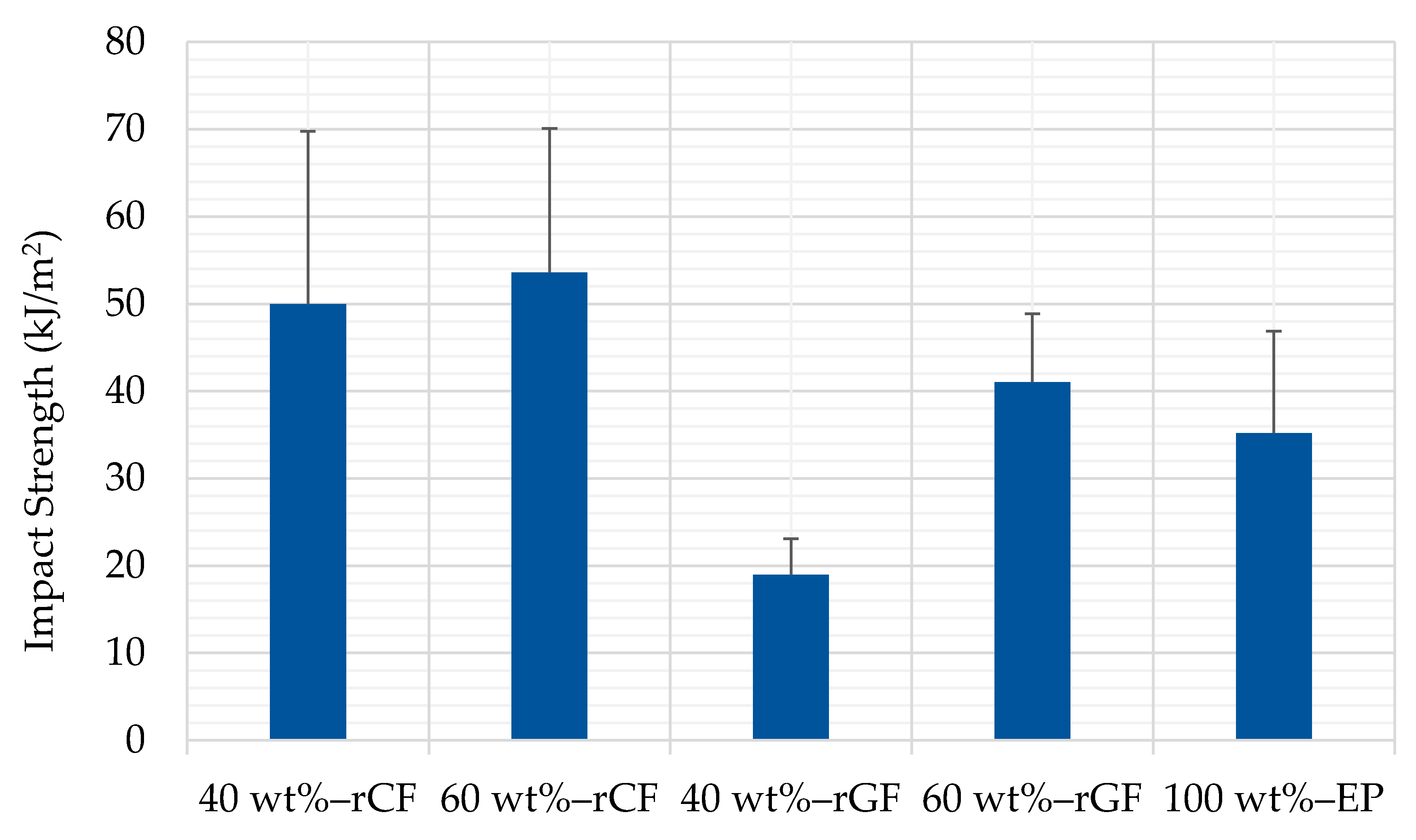
Figure 10 presents the average values from the measured unnotched charpy impact test. The error bars display the calculated standard deviation for each sample type. The increase in ≈20 wt% fibre volume resulted in a 3.63 kJ/m
2 strength increase for the rCF/EP and 22.06 kJ/m
2 for the rGF/EP composites. The increase in the fibre fraction had a significant influence on the rGF/EP composites compared to the rCF/EP composites, in which the strength increase was negotiable. This variation in impact strength could be related to the size effect on the energy dissipation. Typically, a rougher microstructure results in composites with higher impact strength [
23]. Another well-known reason is the interfacial strength between the fibre-matrix interface, in which a lower interfacial strength results in a higher impact strength [
24]. The additional fibres made the rGF/EP composites tougher. However, this was absent in the rCF/EP composites. This could be due to a lack of fibres that were thoroughly wet by the resin system. Even though the thermal recycling of GF results in an overall decrease in mechanical strength, it does not degrade their stiffness properties after recycling [
18].
3.3. Composite Investigation
3.3.1. Tested Composites
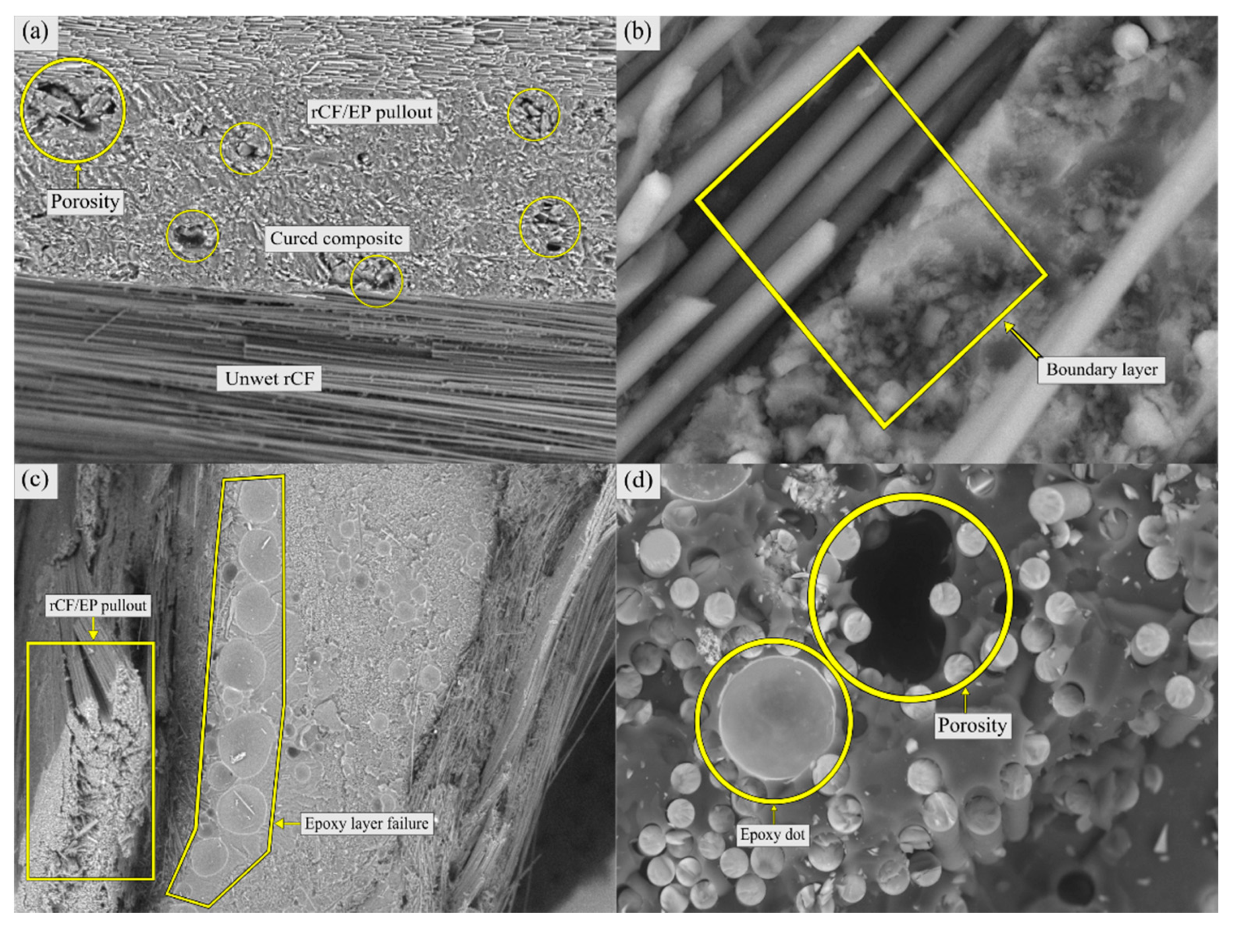
Figure 11 represents the defects observed in the CMCs. The remanufacturability of both the rCF/EP and rGF/EP composites was investigated using SEM after the mechanical tests. In the rCF/EP composites, boundary layers between fully cured fibres and unwet fibres (
Figure 11a,b) and minor voids (
Figure 11a) were observed. The boundary between fully cured and unwet fibres explains the manual LBL bundle-based fibre arrangement during the CM process, in which the resin system failed to spread evenly inside the aligned rCF bundles (
Figure 11b). Such evidence was also present in the fibre pull-out samples, where the failure layers of the resin system are visible (
Figure 11c).
In the rGF/EP composites, the remanufactured composites appeared fully cured, without any signs of non-wet fibres. However, the samples showed evidence of microvoids and resin spots (
Figure 11d). Utilising a higher heating rate will rapidly evaluate the matrix phase (volatile materials), eventually resulting in the formation of porous structures. Additionally, due to rapid volatilisation, void formation increases as a result of higher pressure [
25]. Such evidence for the formation of minor porous structures was present in the SEM images for both the rCF/EP and rGF/EP composites (
Figure 11a,d).
3.3.2. rCF/EP Composite
When comparing the measured properties of the rCF/EP composites from this study to similar studies in the literature, the values fall under the related limits. A study that adopted fluidised bed process (FBP), by Shah and Schubel [
26], used an aligned non-woven mat of rCF recycled composites with a fibre volume of 27–34 wt%, a TS of 133–174 MPa, and a YM 19–32 GPa. The composites were remanufactured using liquid composite moulding. Similar aligned non-woven fibres with 30 wt% rCF composites were studied by Pimenta et al. [
19,
22], and had a TS of 194 MPa and a YM of 28 GPa. The study implemented pyrolysis to recycle the CFs, and resin film infusion to remanufacture them. Apart from the aligned composites, the random fibre alignment and discontinuous fibres also had values under those of the related limits. A study by Wong et al. [
27] using compression moulding produced composites values of TS of 207 MPa and YM of 25 GPa, with 30 wt% rCFs. Another study by Feraboli et al. [
28], with long and random fibre orientation, resulted in a TS of 196.5 MPa and YM of 29 GPa with 33 wt% rCFs.
The SEM images show various noticeable defects in the rCF/EP composites; apart from the visible defects, further investigation was performed to analyse the factors influencing the rCF/EP composite properties. The fibre alignment and length had a significant influence over the mechanical properties of the rCF composites [
13]. These two factors can also be related to both the newly manufactured rCF/EP and rGF/EP composites.
The rCFs were manually realigned to produce both the rCF/EP composite types (40 and 60 wt%). Randomly oriented fibres lead to a non-homogenous outcome [
26]. With a higher fibre content (60 wt% rCF) and continuous UD composites, even a minor fibre misalignment by 10° will result in a strength loss of up to 50%. This strength loss does not have an impact on the YM of the composites [
29,
30,
31,
32]. Even though the fibres appeared to be UD, the varying results between each sample from the population, as represented as error bars in
Figure 8, suggest the possibility of fibre misalignment. To overcome such misalignments, recent studies by HiPerDiF team [
33] of the University of Bristol proposed an automated realignment method, but they are suitable only for discontinuous fibre composites. Additionally, CM also induces a certain level of fibre misalignment due to the compressive forced applied to the composites before curing.
The employed long rCFs in the composites were intended to preserve the fibre integrity, so that it will be easy to recycle again after reusing. Even though longer fibres increase the lamination stiffness of the composite [
13], employing them increases the overall brittleness of the composite [
3,
20]. The ≈20 wt% rCF addition increased the YM of the composites but at the same time made the composites more brittle, leading to an increased likelihood of brittle failure.
Apart from the fibre-based factors, the fibre-matrix interface can also influence the mechanical properties of the rCF/EP composites. The fluffy nature of rCFs makes it hard for the resin system to wet the fibres thoroughly. This can result in unevenly cured composites (
Figure 11a,b). Such unwet fibre spots appear to be the origin for failure, making the composites behave non-linearly. This can be avoided by using shorter fibres [
34], or by increasing the number of active atoms and functional groups on the surface of the inert rCFs [
35] to improve the overall wettability for all fibre lengths.
3.3.3. rGF/EP Composite
When comparing the measured properties of the rGF/EP composites from this study to similar studies in the literature, the values fall under the related limits. A study which adopted thermal burning, by Fraisse et al. [
36], used a UD-aligned non-woven mat rGF composites, recycled with a fibre volume of 46.8 ± 1.1 wt%, with a TS of 120 ± 20 MPa and YM of 45.1 ± 4.7 GPa. The composites were remanufactured using resin transfer moulding. Similar UD-aligned non-woven fibres with 63 wt% rGF composites by Yang et al. [
24] had a TS of 85 MPa and YM of 14.3 GPa.
Recycling GF utilising thermal recycling processes has frequently resulted in a strength loss of the rFs [
37,
38,
39]. Notably, both well-known thermal recycling processes, FBP and the pyrolysis process, result in strength loss in rGFs. The process temperature has a significant role in influencing rGF properties. Clean rGFs with minimal impurities are obtained between 400 and 600 °C. It has been observed that, at a higher temperature range, cleaner rGFs are obtained. However, GFs start to gradually lose their strength above 300 °C [
38,
39,
40]. The strength decrease appears to be an effect of heat penetrating the GF, resulting in etching of the rGF surface. However, it can be reduced using secondary strength recovery treatments, resulting in a reduced rGF diameter and an increase in the overall mechanical properties [
24]. After the commonly used thermal recycling processes, supercritical fluid-based solvolysis also results in a similar decrease in the mechanical properties of the rGFs, due to the influence of heat [
37].
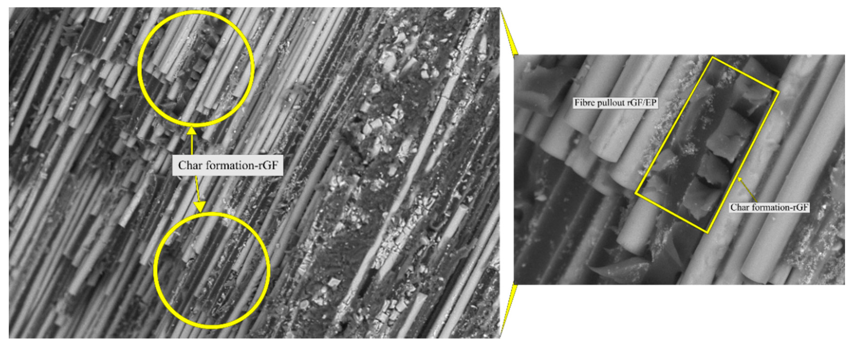
Another noticeable defect of thermal recycling of GF appears to be the formation of char (resin residue). Char can be associated with inappropriate materials burning during the recycling process. In thermal degrading polymer resins, char formation is inevitable. The formed chars possess low thermal conductivity and insulate the heat from completely oxidising the resin phase [
41]. More char indicates a weaker performance of the recycling process. SEM images confirm the presence of minor char formation, with a shear-type failure in the composite (
Figure 12). Such char formations can be removed by utilising supplementary treatments. However, this study does not focus on char removal and secondary strength recovery treatments for rGFs. The evidence of char formation was minimal in rCFs.
Alongside char located on the bottom layer of the rFs, a small quantity of ash appeared on the heat exposed surface. This could be the result of direct heat exposure. Despite some flaws, electrostatic attraction [
36] between individual fibres was absent, making it easy to produce composites with a higher fibre volume fraction (up to 60 wt%). In the CMCs, fibres were uniformly distributed and thoroughly reinforced with the epoxy resin system, with less porosity (
Figure 11d).
In addition to the thermal treatment, mechanical handling and fibre realignment during the remanufacturing of the rGFs also influence the mechanical properties [
40]. As noted in rCF/EP composites, the rGF/EP composites were also influenced by fibre realignment. The error bar displays the variation from the measured sample population, which is not as strong as for rCF/EP composites. The 60 wt% rGF/EP composites had the minimum CoV between samples compared to other composites.
During the remanufacturing stage, rGF-reinforced with new thermosetting resins (e.g., epoxy) had decreased TS. However, the YM of the composites remained the same, compared to their virgin properties [
4]. These behaviours can be seen in the measured mechanical properties (
Table 2). For both cases (40 and 60 wt% rGFs), the YM of the CMCs was higher compared to its TS. The addition of ≈20 wt% rGFs improved the TS and IS, but the YM showed only a minor increase, indicating no change to the CMC’s elastic region.
4. Conclusions
In this study, the composite wastes were recycled, remanufactured and investigated. The study utilised a novel thermal recycling process to recover the CFs and GFs and reuse the rCFs and rGFs into new fibre-reinforced epoxy composites via compression moulding. Finally, investigation on the rCF/EP and rGF/EP composites were conducted using standardised mechanical testing.
Both the CFs and GFs were successfully recycled from manufacturing waste (pre-consumer wastes) by a novel thermal recycling process. The recycled fibres, both rCF and rGF, showed evidence of a cleaner and resin-free fibre surface. The recovery rate of the rCFs was 95–98 wt%, while the rate was 80–82 wt% for rGFs, at an optimum temperature of 550 °C at atmospheric pressure. The processing time in the batch reactor was 20–25 min for rCFs and 25–30 min for rGFs. The recycling process can altogether remove the matrix phase of the composite without causing any damage to the fibres and their structure.
The newly produced composites rCF/EP and rGF/EP can be used in various applications. An increase in fibre content (≈20 wt%) in the rCF/EP composites did not cause a substantial increase in its TS. However, the TS of the rGF/EP composites almost doubled from its initial value. For the YM, the rGF/EP had no noticeable effect, but a significant rise was observed in the rCF/EP composites. The composites have certain factors which negatively influence their mechanical properties, among which poor wettability of resin to the rCF surface was a significant factor for the rCF/EP composites. Similarly, for rGF/EP composites, char formation (matrix residue) and fibre strength loss due to the thermal-based recycling were significant factors. To further utilise the recycled composites and establish continuous closed-loop recycling, these factors should be eradicated by implementing additional treatments.
Future research should investigate the mechanical properties of the remanufactured fibres using finite element methods (FEMs), and compare the values with experimental results. This kind of approach should also incorporate the investigation of the possible applications in which the newly produced composites can be utilised. Furthermore, performing life-cycle analysis (LCA) on the recycling process will provide insights into the sustainable aspects of the process.
Author Contributions
S.K.G. performed the laboratory work, prepared the samples, tested the materials, performed the investigation, analysed the results, and wrote this manuscript. T.K. contributed to the methodology section, provided feedback on the manuscript, and supervised the project. All authors have read and agreed to the published version of the manuscript.
Funding
This research received no external funding.
Conflicts of Interest
The authors declare no conflict of interest.
References
- Gopalraj, S.K.; Kärki, T. A review on the recycling of waste carbon fibre/glass fibre-reinforced composites: Fibre recovery, properties and life-cycle analysis. SN Appl. Sci. 2020, 2, 433. [Google Scholar] [CrossRef] [Green Version]
- Pimenta, S.; Pinho, S.T. Recycling carbon fibre reinforced polymers for structural applications: Technology review and market outlook. Waste Manag. 2011, 31, 378–392. [Google Scholar] [CrossRef] [PubMed] [Green Version]
- Oliveux, G.; Dandy, L.O.; Leeke, G.A. Current status of recycling of fibre reinforced polymers: Review of technologies, reuse and resulting properties. Prog. Mater. Sci. 2015, 72, 61–99. [Google Scholar] [CrossRef] [Green Version]
- Beauson, J.; Lilholt, H.; Brøndsted, P. Recycling solid residues recovered from glass fibre-reinforced composites—A review applied to wind turbine blade materials. J. Reinf. Plast. Compos. 2014, 33, 1542–1556. [Google Scholar] [CrossRef]
- Palmer, J.; Ghita, O.R.; Savage, L.; Evans, K.E. Successful closed-loop recycling of thermoset composites. Compos. Part A Appl. Sci. Manuf. 2009, 40, 490–498. [Google Scholar] [CrossRef]
- Tapper, R.J.; Longana, M.L.; Yu, H.; Hamerton, I.; Potter, K.D. Development of a closed-loop recycling process for discontinuous carbon fibre polypropylene composites. Compos. Part B Eng. 2018, 146, 222–231. [Google Scholar] [CrossRef] [Green Version]
- Hazell, J. Getting it right from the start: Developing a circular economy for novel materials. Green Alliance 2017, 3–36. [Google Scholar]
- Hagnell, M.K.; Åkermo, M. The economic and mechanical potential of closed loop material usage and recycling of fibre-reinforced composite materials. J. Clean. Prod. 2019, 223, 957–968. [Google Scholar] [CrossRef]
- Asmatulu, E.; Twomey, J.; Overcash, M. Recycling of fiber-reinforced composites and direct structural composite recycling concept. J. Compos. Mater. 2014, 48, 593–608. [Google Scholar] [CrossRef]
- Onwudili, J.A.; Insura, N.; Williams, P.T. Autoclave pyrolysis of carbon reinforced composite plastic waste for carbon fibre and chemicals recovery. J. Energy Inst. 2013, 86, 227–232. [Google Scholar] [CrossRef] [Green Version]
- Goodship, V. Management, Recycling and Reuse of Waste Composites, 1st ed.; Woodhead Publishing Limited: Cambridge, UK, 2010; pp. 70, 92, 109, 110. [Google Scholar]
- Rodrigues, G.G.M.; de Paiva, J.M.F.; Carmo, J.B.D.; Botaro, V.R. Recycling of carbon fibers inserted in composite of DGEBA epoxy matrix by thermal degradation. Polym. Degrad. Stab. 2014, 109, 50–58. [Google Scholar] [CrossRef]
- Gillet, A.; Mantaux, O.; Cazaurang, G. Characterisation of composite materials made from discontinuous carbon fibres within the framework of composite recycling. Compos. Part A Appl. Sci. Manuf. 2015, 75, 89–95. [Google Scholar] [CrossRef]
- SFS-EN ISO 527-2. Plastics—Determination of Tensile Properties—Part 2: Test Conditions for Moulding and Extrusion Plastics; ISO: Helsinki, Finland, 2012. [Google Scholar]
- SFS-EN ISO 179-1. Plastics—Determination of Charpy Impact Properties—Part 1: Non-Instrumented Impact Test; ISO: Helsinki, Finland, 2010. [Google Scholar]
- Meyer, L.O.; Schulte, K.; Grove-Nielsen, E. CFRP-recycling following a pyrolysis route: Process optimisation and potentials. J. Compos. Mater. 2009, 43, 1121–1132. [Google Scholar] [CrossRef] [Green Version]
- Ma, C.; Sánchez-Rodríguez, D.; Kamo, T. Influence of thermal treatment on the properties of carbon fiber reinforced plastics under various conditions. Polym. Degrad. Stab. 2020, 178, 109199. [Google Scholar] [CrossRef]
- Feih, S.; Boiocchi, E.; Mathys, G.; Mathys, Z.; Gibson, A.G.; Mouritz, A.P. Mechanical properties of thermally-treated and recycled glass fibres. Compos. Part B Eng. 2011, 42, 350–358. [Google Scholar] [CrossRef] [Green Version]
- Pimenta, S.; Pinho, S.T. The effect of recycling on the mechanical response of carbon fibres and their composites. Compos. Struct. 2012, 94, 3669–3684. [Google Scholar] [CrossRef] [Green Version]
- Greenhalgh, E.S. Failure Analysis and Fractography of Polymer Composites; Woodhead Publishing Limited: Cambridge, UK, 2009; pp. 194, 279–350. [Google Scholar]
- Rahimizadeh, A.; Tahir, M.; Fayazbakhsh, K.; Lessard, L. Tensile properties and interfacial shear strength of recycled fibers from wind turbine waste. Compos. Part A Appl. Sci. Manuf. 2020, 131, 105786. [Google Scholar] [CrossRef]
- Pimenta, S.; Pinho, S.T.; Robinson, P.; Wong, K.H.; Pickering, S.J. Mechanical analysis and toughening mechanisms of a multiphase recycled CFRP. Compos. Sci. Technol. 2020, 70, 1713–1725. [Google Scholar] [CrossRef] [Green Version]
- Pimenta, S.; Pinho, S.T. The influence of micromechanical properties and reinforcement architecture on the mechanical response of recycled composites. Compos. Part A Appl. Sci. Manuf. 2014, 56, 213–225. [Google Scholar] [CrossRef] [Green Version]
- Yang, L.; Sáez, E.R.; Nagel, U.; Thomason, J.L. Can thermally degraded glass fibre be regenerated for closed-loop recycling of thermosetting composites? Compos. Part A Appl. Sci. Manuf. 2015, 72, 167–174. [Google Scholar] [CrossRef] [Green Version]
- Hao, S.; Kuah, A.T.; Rudd, C.D.; Wong, K.H.; Lai, N.Y.; Mao, J.; Liu, X. A circular economy approach to green energy: Wind turbine, waste, and material recovery. Sci. Total Environ. 2020, 702, 135054. [Google Scholar] [CrossRef] [PubMed]
- Shah, D.U.; Schubel, P.J. On recycled carbon fibre composites manufactured through a liquid composite moulding process. J. Reinf. Plast. Compos. 2016, 35, 533–540. [Google Scholar] [CrossRef]
- Wong, K.H.; Pickering, S.J.; Turner, T.A.; Warrior, N.A. Compression moulding of a recycled carbon fibre reinforced epoxy composite. In Proceedings of the International SAMPE Symposium and Exhibition, Baltimore, MD, USA, 18 May 2009; Volume 54. [Google Scholar]
- Feraboli, P.; Kawakami, H.; Wade, B.; Gasco, F.; DeOto, L.; Masini, A. Recyclability and reutilization of carbon fiber fabric/epoxy composites. J. Compos. Mater. 2012, 46, 1459–1473. [Google Scholar] [CrossRef]
- Bednarcyk, B.A.; Aboudi, J.; Arnold, S.M. The effect of general statistical fiber misalignment on predicted damage initiation in composites. Compos. Part B Eng. 2014, 66, 97–108. [Google Scholar] [CrossRef] [Green Version]
- van de Werken, N.; Reese, M.S.; Taha, M.R.; Tehrani, M. Investigating the effects of fiber surface treatment and alignment on mechanical properties of recycled carbon fiber composites. Compos. Part A Appl. Sci. Manuf. 2019, 119, 38–47. [Google Scholar] [CrossRef]
- Rouhi, M.S.; Juntikka, M.; Landberg, J.; Wysocki, M. Assessing models for the prediction of mechanical properties for the recycled short fibre composites. J. Reinf. Plast. Compos. 2019, 38, 454–466. [Google Scholar] [CrossRef]
- Oliveux, G.; Bailleul, J.-L.; Gillet, A.; Mantaux, O.; Leeke, G.A. Recovery and reuse of discontinuous carbon fibres by solvolysis: Realignment and properties of remanufactured materials. Compos. Sci. Technol. 2017, 139, 99–108. [Google Scholar] [CrossRef] [Green Version]
- HiPerDiF. Available online: http://www.bristol.ac.uk/composites/research/hiperdif/ (accessed on 18 March 2020).
- Zabihi, O.; Ahmadi, M.; Liu, C.; Mahmoodi, R.; Li, Q.; Naebe, M. Development of a low cost and green microwave assisted approach towards the circular carbon fibre composites. Compos. Part B Eng. 2020, 184, 107750. [Google Scholar] [CrossRef]
- Liu, F.; Shi, Z.; Dong, Y. Improved wettability and interfacial adhesion in carbon fibre/epoxy composites via an aqueous epoxy sizing agent. Compos. Part A Appl. Sci. Manuf. 2018, 112, 337–345. [Google Scholar] [CrossRef]
- Fraisse, A.; Beauson, J.; Brøndsted, P.; Madsen, B. Thermal recycling and remanufacturing of glass fibre thermosetting composites. Iop Conf. Ser. Mater. Sci. Eng. 2016, 139, 012020. [Google Scholar] [CrossRef] [Green Version]
- Sokoli, H.U.; Beauson, J.; Simonsen, M.E.; Fraisse, A.; Brøndsted, P.; Søgaard, E.G. Optimised process for recovery of glass- and carbon fibers with retained mechanical properties by means of near- and supercritical fluids. J. Supercrit. Fluids 2017, 124, 80–89. [Google Scholar] [CrossRef]
- Åkesson, D.; Foltynowicz, Z.; Christéen, J.; Skrifvars, M. Microwave pyrolysis as a method of recycling glass fibre from used blades of wind turbines. J. Reinf. Plast. Compos. 2012, 31, 1136–1142. [Google Scholar] [CrossRef]
- Zheng, Y.; Shen, Z.; Ma, S.; Cai, C.; Zhao, X.; Xing, Y. A novel approach to recycling of glass fibers from nonmetal materials of waste printed circuit boards. J. Hazard. Mater. 2009, 170, 978–982. [Google Scholar] [CrossRef] [PubMed]
- Jenkins, P.G.; Yang, L.; Liggat, J.J.; Thomason, J.L. Investigation of the strength loss of glass fibre after thermal conditioning. J. Mater. Sci. 2015, 50, 1050–1057. [Google Scholar] [CrossRef] [Green Version]
- Dao, D.Q.; Luche, J.; Richard, F.; Rogaume, T.; Bourhy-Weber, C.; Ruban, S. Determination of characteristic parameters for the thermal decomposition of epoxy resin/carbon fibre composites in cone calorimeter. Int. J. Hydrog. Energy 2013, 38, 8167–8178. [Google Scholar]
© 2020 by the authors. Licensee MDPI, Basel, Switzerland. This article is an open access article distributed under the terms and conditions of the Creative Commons Attribution (CC BY) license (http://creativecommons.org/licenses/by/4.0/).


