Article

A Study of Electrical Aging of the Turn-to-Turn Oil-Paper Insulation in Transformers with a Step-Stress Method

Key Laboratory of Engineering Dielectrics and Its Application, Ministry of Education, Harbin University of Science and Technology, Harbin 150080, China
*
Author to whom correspondence should be addressed.
Energies 2018, 11(12), 3338; https://doi.org/10.3390/en11123338
Submission received: 22 October 2018 / Accepted: 8 November 2018 / Published: 30 November 2018
(This article belongs to the Section F: Electrical Engineering)

Abstract

:
This study investigates the electrical aging characteristics of oil-paper composite insulation. In this paper, a coils model and test system for oil-paper transformer insulation are designed. The electrical aging tests of the model coils at room temperature and operating temperature are performed using the step-stress method. A new method for estimating the unknown parameters in the inverse power exponent model is proposed, and the inverse power model life formula expressed by voltage and electric field strength is obtained. Considering the electrical aging process at the operating temperature, the allowable field strength of the inter-turn insulation of oil-immersed transformers can be improved. The new parameter estimation method proposed in this paper can be used to calculate the unknown parameters of the step-stress solid insulation aging model. This method has a clear physical meaning and can be solved easily. When the stressed voltage is below a certain threshold value, the life of the transformer coil turn-to-turn insulation grease oiled paper model is longer at operating temperatures compared with that at room temperature; when the voltage is higher than the threshold, it presents the opposite tendency.

1. Introduction

As the core component of power systems, failure of a power transformer results in direct or indirect economic losses, which directly affect the security of the power grid [1,2,3]. It has been reported that many transformers in service around the world are close to or beyond the end of their design life expectancy [4], so understanding the aging mechanism of transformer insulation systems is crucial [5]. The insulation properties of the turn-to-turn insulation in oil-immersed transformer insulation systems are very important. The breakdown of turn-to-turn insulation occurs occasionally, and a failed transformer is difficult to repair. The aging of oil-immersed paper insulation is influenced by the electric field, temperature, moisture, oxygen, and other factors [6,7,8,9]. Among these factors, the damage caused by electrical aging cannot be ignored [10,11]. Understanding the electrical aging properties of oil-immersed paper insulation under various temperatures, evaluating the insulation properties of a power transformer late in its life, and then adopting a flexible life cycle greatly improves the economy and reliability of a power grid operation [12,13].
Because the life of a power transformer is very long and the insulation system aging process is very slow under nominal stress, aging tests always adopt accelerated aging methods, and the transformer lifespan under the normal working state is then calculated [14,15,16,17]. According to the loading conditions of stress, accelerated life tests of insulating materials are divided into constant voltage tests, step-stress voltage tests, and sequence voltage tests [18]. The constant voltage method is the most widely used, but the choice of the test voltage is made blindly and valid data cannot be obtained within a short period of time [19]. In recent years, some researchers have tested the electrical aging life of polypropylene and polyimide films, and obtained good results using the step-stress method. However, the estimated parameters of the solid insulation power model are obtained using partial differential equations, which are difficult to solve by the traditional maximum likelihood method [20,21,22,23,24].
Electrical aging of insulating materials caused by partial discharge (PD) has been extensively studied [25,26]. Partial discharges are key events for insulation diagnosis of power transformers, which is an important means of evaluating the insulation status [27]. The correlation between the PD characteristic parameters and the degree of insulation aging has been established [28]. The changing trend of the PD characteristic parameters have been researched during the aging process of the insulating material to characterize insulation aging [29]. PD is a complex physical process, so PD measurement methods have been widely studied [30]. The pulse current method has the advantages of simple operation and high sensitivity, which has been widely recognized by researchers. In this paper, the pulse current method is used to detect the PD of the sample.
In this paper, we design a model and test system for oil-immersed transformer turn-to-turn insulation and use the step-stress method for testing the electrical aging at room temperature (22 °C) and operating temperature (80 °C). A new parameter estimation method is proposed to increase the speed of solving the inverse power equation, which can replace the traditional complicated maximum likelihood method. A constant stress aging test is used to verify the correctness of the parameter estimation method, and the results of the test are analyzed. In addition, to make the results more universal, we calculate the electric field expressed as an inverse power model of the transformer turn-to-turn insulation and explain the difference between using the actual value and the calculated value for the long-term operation field. The results of this paper provide theoretical support for the aging mechanism of oil-immersed power transformers and oil-immersed insulation using multiple factors, as well as the structural design of turn-to-turn insulation.

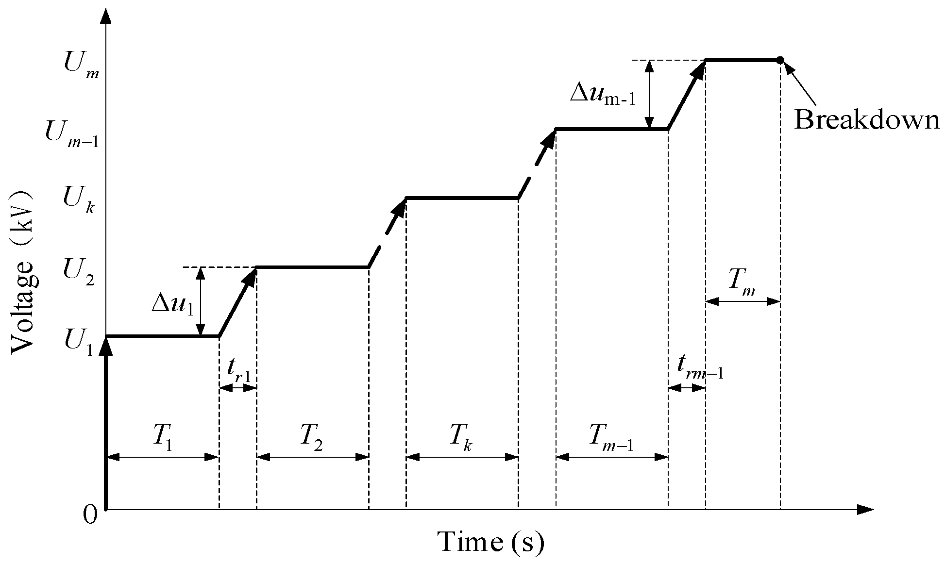
2. Electric Aging Theory of Oil-Immersed Insulation under Step Stress

The turn-to-turn insulation of oil-immersed transformers is mainly oil-immersed paper. The electrical aging life of solid insulation obeys the power law, namely:
L = A U N
where U—applied voltage; L—insulation life; N—a constant, related to the material performance and the electrical aging mechanism; A—a constant, related to the temperature and geometric shape of the test object.
By Equation (1):
U N L = A
where A is the metric of insulation life, subject to all aging processes.
Solid insulation failure has a cumulative effect that meets the Nelson model, that is, in the process of electrical insulation aging, the remaining life of the insulation is determined only by the current state of the insulating material, the voltage applied to the insulating material, and the breakdown probability in the current state, but has nothing associated with its historical process. There are different methods to calculate the insulation aging process from the initial state to the present state, but the residual life is the same [31]. As a result, the step-stress method can be used for the accelerated electrical aging test of the coil turn-to-turn insulation. The testing process of the step-stress method is shown in Figure 1.
Uk (k = 1... m) is the voltage at k level; ΔUk (k = 1... m − 1) is step length of voltage; Trk (k = 1... m − 1) is the rising time for the No. k step voltage; T1 = T2 =... = Tk =... = Tm−1 is the stress time, Tm is holding time of the final stress; M is the number of the stress index.
Since it is typical that Trk < < Tk in the step-stress test, it is thought that the rising process can be ignored. By Equation (2), based on the accumulation of solid insulation electrical aging characteristics and the Nelson model, with different Uk and Tk:
k = 1 m 1 U k N T k + U m N T m = constant
If we do not consider the randomness of breakdown, Equation (3) should be equal to Equation (2). For the step-stress test, Tk in Equation (3) can be classified the same as T0, so Equation (3) becomes:
T 0 k = 1 m 1 U k N + U m N T m = A
The step-stress aging test is usually performed with many samples under different T0, so that we obtain many groups of T0, Tm, Uk, and Um after the test is completed. By means of the appropriate method, the constants N and A are solved; then the power model life-cycle equation is obtained.

3. Electrical Aging Test for Coil Model
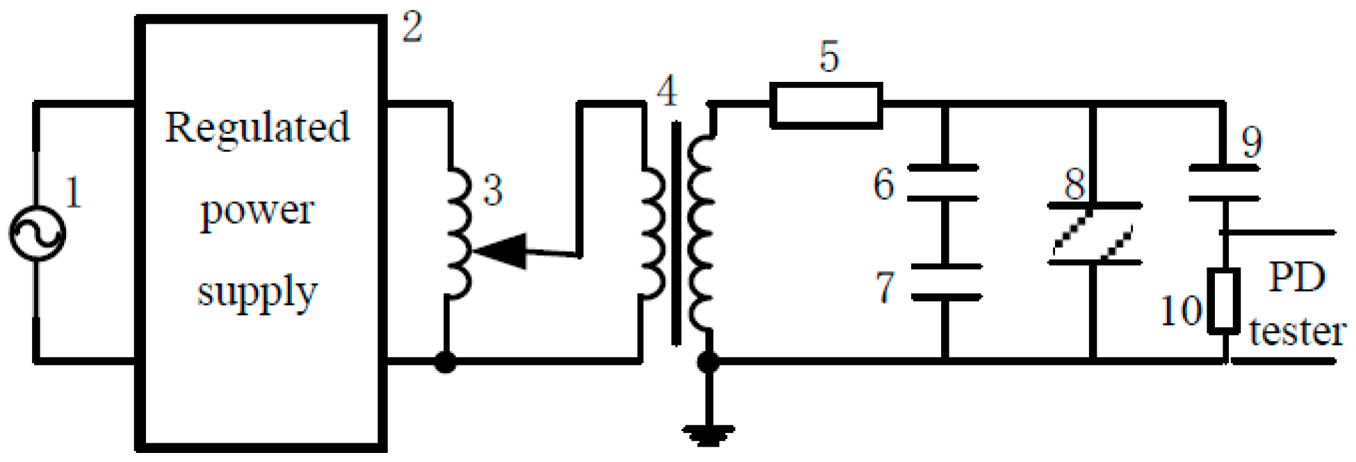
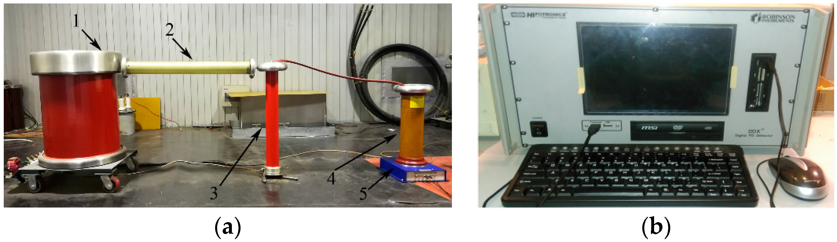
The step-stress method is selected to conduct the accelerated aging test for the oil-immersed paper insulation at room temperature and operating temperature. The sample’s breakdown is defined as the end-of-life, and the holding time to breakdown is called the length-of-life. At the same time, the PD inception voltage is also monitored.

3.1. Test Circuit

Figure 2 shows the electrical aging test circuit for the turn-to-turn oil-paper insulation.
In the Figure 2, 1 is the power grid; 2 is the regulated power supply; 3 is the self-coupling transformer; 4 is no partial discharge transformer; 5 is the protective resistor; 6 is the capacitive voltage divider high-voltage arm; 7 is the capacitive voltage divider low-voltage arm; 8 is the sample; 9 is the coupling capacitor; 10 is the testing impedance.

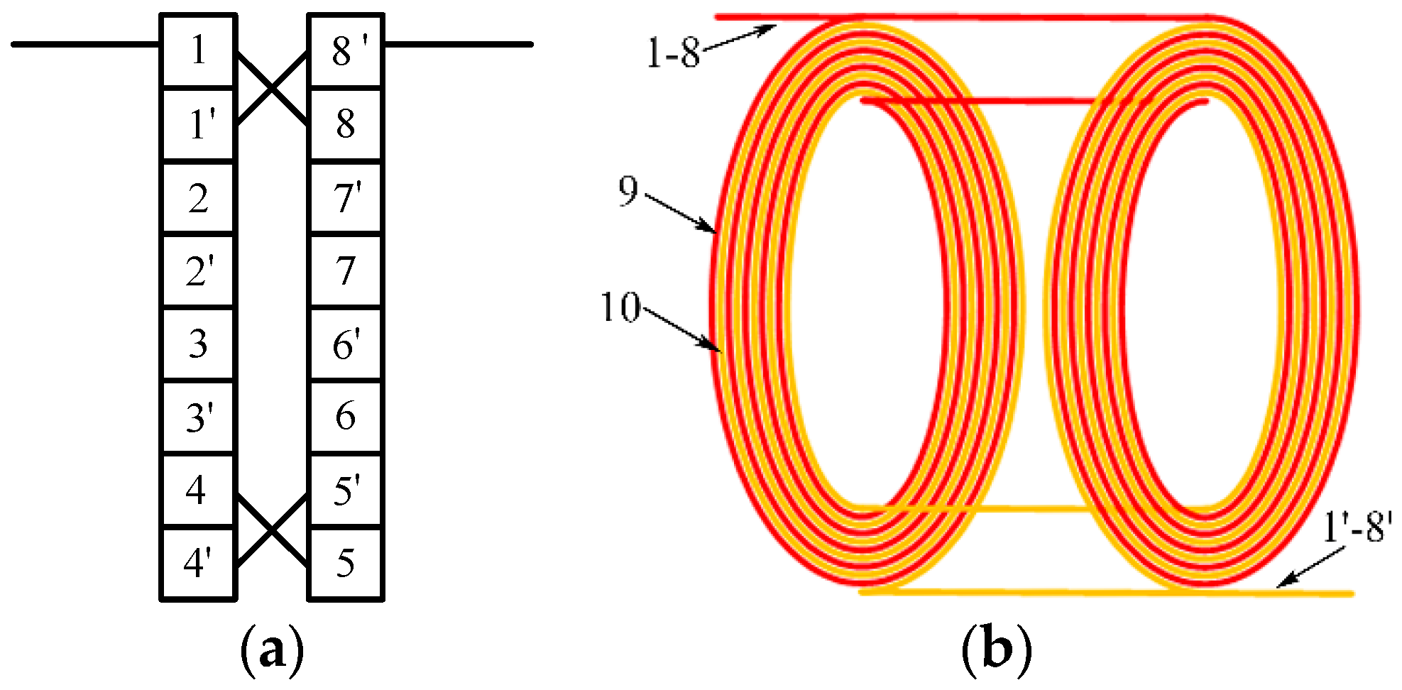
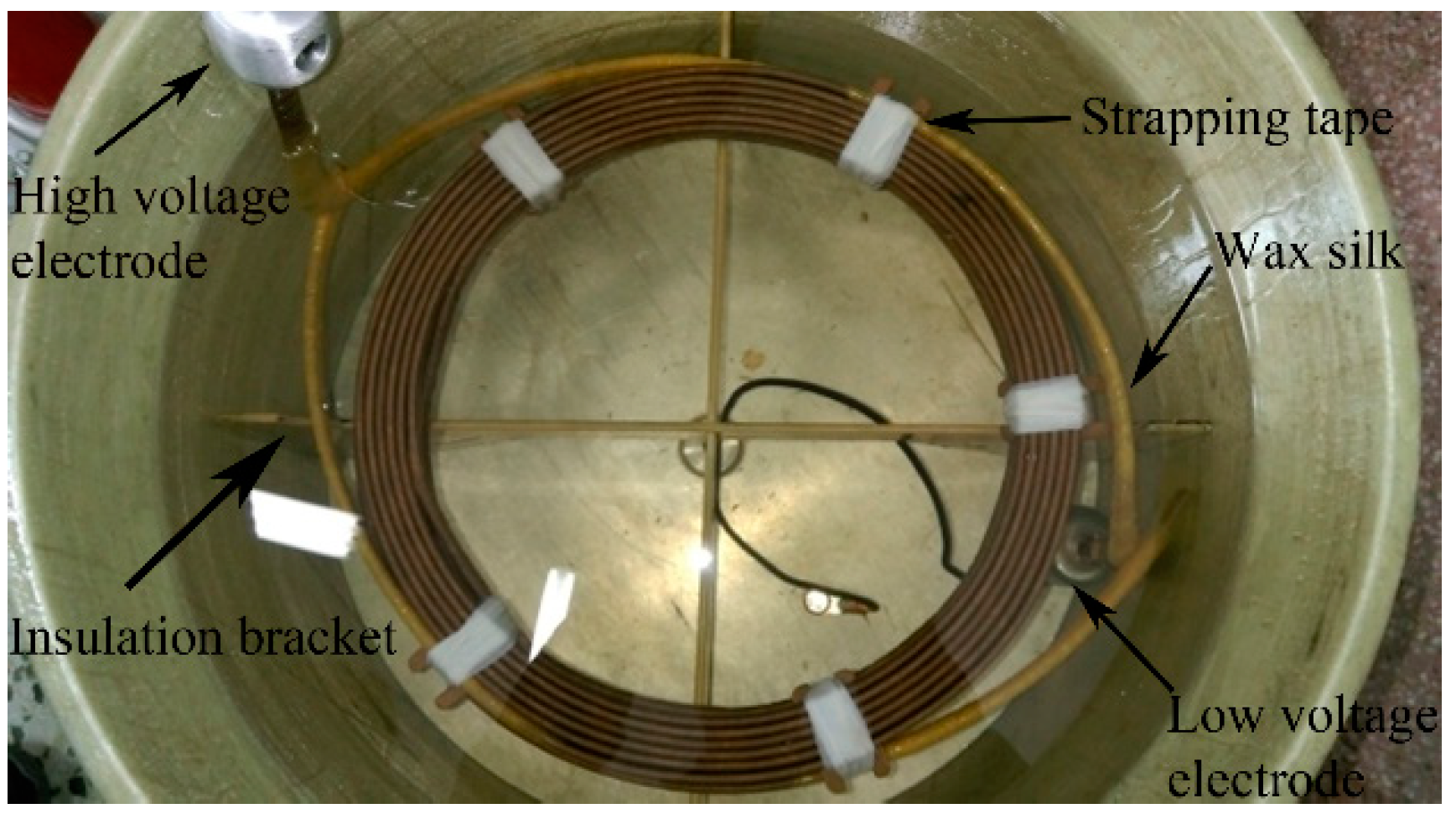
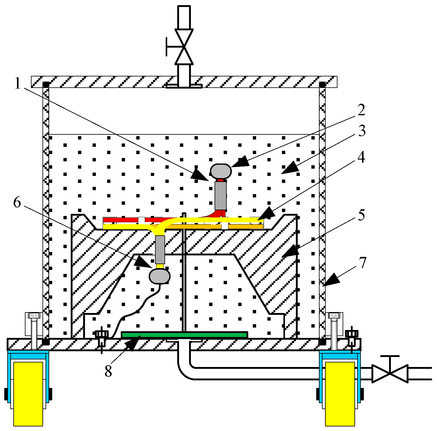
3.2. Coil Model and Test System

A model coil with the same specifications as the 500-kV power transformer winding wire was produced. The parameters are as follows: outer diameter is 350 mm; inner diameter is 274 mm; 10 turns; thickness of turn insulation is 2.35 mm; cross section of conductor is a × b = 2 mm × 10 mm; chamfering radius R is 0.8 mm. Using two pieces of paper-covered wound wire, the double matted wound method is shown in Figure 3a, where 1–8 is the same wire and 1′–8′ is another wire. In Figure 3b, 9 is the high voltage coil and 10 is the low voltage coil.
The structure of the actual coil model is shown in Figure 4, where strapping tape is used to fix the high voltage coil and the low voltage coil, and wax silk is wound around the coil terminal in order to prevent PD at the outlet end of the sample.
As shown in Figure 5, the test tank in this paper can be evacuated and heated to a constant temperature.
In Figure 5, 1 is the high-voltage coil terminal; 2 is the voltage equalizing electrode; 3 is the transformer oil; 4 is the test coil; 5 is the insulation bracket; 6 is the low-voltage coil terminal; 7 is the insulation cylinder; 8 are the heating and temperature measuring devices. The voltage equalizing electrodes are installed at the high-voltage coil terminal and the low-voltage coil terminal, they can avoid the PD activies out of test samples. Switzerland
The test system of electrical aging is built in the shielding room. As shown in Figure 6, 1 is the self-coupling transformer; 2 is the protection resistor; 3 is the capacitive voltage divider; 4 is the coupling capacitor; 5 is the testing impedance. The PD detector is a DDX-7000 (Hipotronics, Basel, Switzerland) with a sampling frequency of 80 MHz and a sensitivity of 0.1 pC. Before the test is formally carried out, the discharge of the test system is less than 3 pC. The measuring system of PD meets the IEC 60270 standard.

3.3. The Pretreatment of the Sample

In order to reduce the dispersion of test results, before every test, coil samples were vacuum dried and impregnated. In this paper, the deposing device is a vacuum jar, and the testing device is a micro water meter. The testing standards are the same as the actual transformer insulation’s drying standards. The moisture content in the insulating paper is less than 4‰. The drying process is as follows: samples are placed in the vacuum drying chamber and heated to 100 °C for 4 h and then stored in a vacuum at less than 100 mPa and maintained for 16 h. The moisture content of the dried samples is tested, and if the moisture content is larger than 4‰, the drying process is repeated. In addition, transformer oil also carried on the dewatering, degassing, and filtration treatment; the parameters meet the requirements of the IEC 60296-2003 standard.

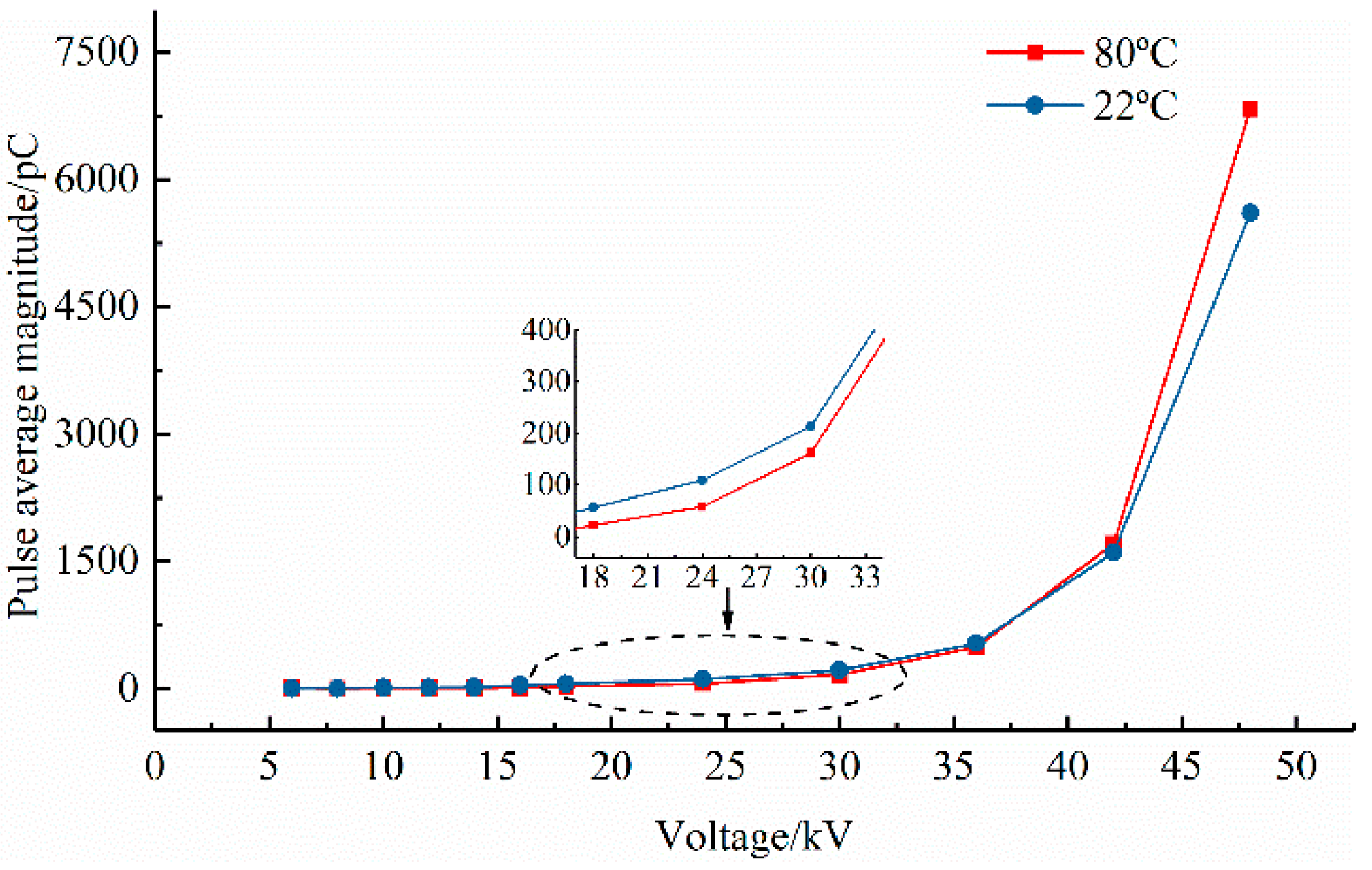
3.4. Preliminary Experiments

In order to obtain the reasonable aging voltage, the preliminary experiment was carried out. The rising speed of the voltage source was 1 kV/s, resulting in the sample breakdown voltage and PD inception voltage, as shown in Table 1.
(1)
The average of PD inception voltage and breakdown voltage is:
U ¯ P D I V = k = 1 14 U P D I V ( k ) = 10.8   ( kV ) U ¯ B = k = 1 14 U B ( k ) = 85.93   ( kV )
(2)
The standard deviation of PD inception voltage and breakdown voltage is:
σ P D I V = 1 13 k = 1 14 ( U ¯ P D I V U P D I V ( k ) ) 2 = 0.913   ( kV ) σ B = 1 13 k = 1 14 ( U ¯ B U B ( k ) ) 2 = 4.171   ( kV )
(3)
The minimum PD inception voltage and breakdown voltage estimate values are:
U P D I V min = U ¯ P D I V 3 σ P D I V = 8 . 061   ( kV ) U B min = U ¯ B 3 σ B = 73.417   ( kV )
The breakdown voltage under the step-stress voltage should be lower than that under continuous stress voltage. To make sure that the aging time is long enough and that the PD inception voltage can be observed, the first level of voltage of the step-stress accelerated life testing voltage method and the estimated value are:
U 1 = 0.75 U P D I V min = 6.04575   ( kV ) Δ u = 0.1 ( U B min U P D I V min ) = 6.5356   ( kV )

3.5. Determination of Test Program

We selected normal (room) temperature and operating temperature as the test temperatures for electrical aging tests. According to the results of the preliminary experiments, 360, 720, 1080, 1440, 1800, 2160, 2520, 2880, 3240 and 3600 s are selected as dwell times, respectively. The first level of step-voltage U1 is 6 kV with a rising speed of 1 kV/s, recording the breakdown voltage, step series, and the holding time of the last level voltage of each sample. In principle, using the method of step-stress for electrical aging tests, the shorter the step voltage is, the longer the aging time needed, but the dispersivity of the test data is smaller and the results are closer to the true aging process. By Equation (8), we can see that when the step length is 6.9 kV, at least ten times of stress levels from UPDIVmin to UBmin are needed. Compared with constant stress tests, considering that step-stress tests reduce the breakdown strength of samples, we selected Δu1 = 2 kV as the first six stress levels and Δu2 = 6 kV as the other numbers of stress levels.

4. Data Processing

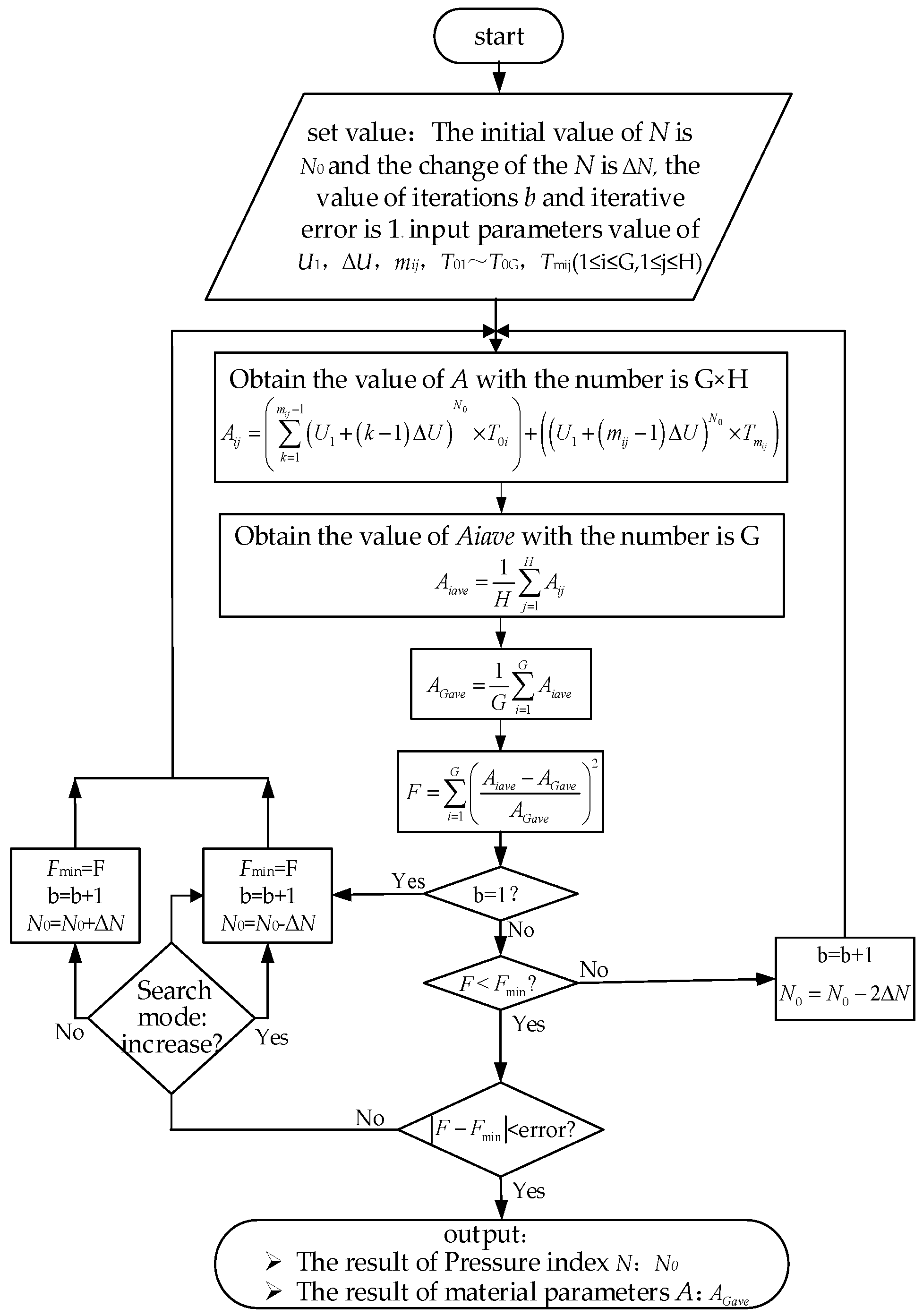
4.1. Explanation of the New Parameter Estimation Method

In the step-stress test method, a number of different holding times T0i are often chosen. Assuming that the number of holding times is G, then T0i = (T01 and T02, ..., ..., T0G). In each holding time T0i, H samples are tested. The voltage resistance index N and the constant A are calculated according to the maximum likelihood method. It is very difficult to obtain the precise solution for the unknown constants N and A represented by Equation (4) using the traditional maximum likelihood method. We propose a new method to solve for the constants N and A. The method is to choose an initial value for N, named N0; then apply Equation (4) to obtain many A values with the number of G × H. For the H samples with holding times T01, T0i, and T0G, we have the following:
{ T 01 k = 1 m 11 1 U k N 0 + U m 11 N 0 T m 11 = A 11 T 01 k = 1 m 12 1 U k N 0 + U m 12 N 0 T m 12 = A 12 T 01 k = 1 m 1 j 1 U k N 0 + U m 1 j N 0 T m 1 j = A 1 j T 01 k = 1 m 1 H 1 U k N 0 + U m 1 H N 0 T m 1 H = A 1 H
{ T 0 i k = 1 m i 1 1 U k N 0 + U m i 1 N 0 T m i 1 = A i 1 T 0 i k = 1 m i 2 1 U k N 0 + U m i 2 N 0 T m i 2 = A i 2 T 0 i k = 1 m i j 1 U k N 0 + U m i j N 0 T m i j = A i j T 0 i k = 1 m i H 1 U k N 0 + U m i H N 0 T m i H = A i H
{ T 0 G k = 1 m G 1 1 U k N 0 + U m G 1 N 0 T m G 1 = A G 1 T 0 G k = 1 m G 2 1 U k N 0 + U m G 2 N 0 T m G 2 = A G 2 T 0 G k = 1 m G j 1 U k N 0 + U m G j N 0 T m G j = A G j T 0 G k = 1 m G H 1 U k N 0 + U m G H N 0 T m G H = A G H
where i and j are integers, 1≦ iG, 1 ≦ jH; Mij is the stress level index of U; mij is the voltage of the last level; and TMij is the holding time of the last level.
Based on the basic physical process of solid insulation aging, assuming a value of N, the following two types of factors affect the dispersion of the A value: the first type is traditional factors such as the solid insulation material process deviation, inherent defects, operating error, system error, and climate change; the second type is caused by the error between the assumed value of N and its true value.
If we take the average of A values obtained from different holding times, the key factor influencing the result in the deviation of A is the error between the assumed value of N and its true value. According to the step-stress voltage method and the discussion above, it is supposed that the assumed value of N approaches the true value when the dispersion of the average of A values decreases.
According to the basic knowledge of probability and mathematical statistics, the size of the variance of a set of data can characterize the dispersion. The data processing procedure is shown in Figure 7.
Calculating average value Aiave (1 ≦ iG) of Aij obtained by H samples under each hold time as:
A i a v e = 1 H j = 1 H A i j
the average value AGave of Aiave obtained by samples under G different holding times is:
A G a v e = 1 G i = 1 G A i a v e
so that the variance of Aiave and AGave is:
F = i = 1 G ( A i a v e A G a v e A G a v e ) 2
If the assumed value of N0 is the true value of N, the dispersion of A will be minimized, which corresponds to the minimum F. Accordingly, it is supposed that the calculated AGave is the voltage index and the true value of life. Thus, we can use the iteration method to find a minimum F; the corresponding N and AGave is the voltage index and the true value of life.

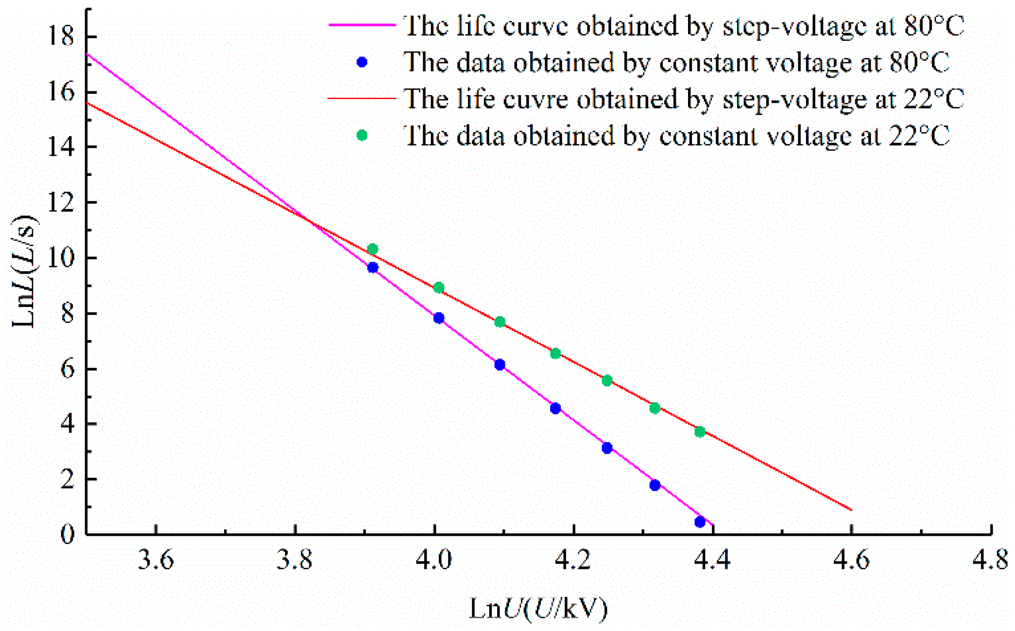
4.2. Solve and Verify the Life Equation

We carried out the step-stress electric aging tests for 100 samples; the experimental results are shown in Table 2. Based on the data in Table 2, we obtained the values for the constant A and voltage life index N; the estimated values at room temperature are 1.39 × 1027 and 13.38, respectively. The estimated value of the constant A and the voltage life index N at the operating temperature are 2.06 × 1036 and 18.92, respectively. Substituting A and N into Equation (1), we obtain the electrical aging reverse power model life formula of oil-paper insulation at room temperature and operating temperature, respectively:
L = 1.39 × 10 27 × U 13.38
L = 2.06 × 10 36 × U 18.92
To verify the correctness of the step-stress accelerated electrical aging life equation, we performed a constant-voltage electrical aging test at normal and operating temperatures. Constant voltages of 40, 45, 50, 55, 60, 65, 70, 75 and 80 kV are selected. We tested six samples for each voltage. As shown in Figure 8, it is seen that the life curve obtained by the step-stress accelerated electrical aging evenly passes through the points of the life data obtained by the constant voltage method, which shows that the step-stress voltage method can be used in oiled paper insulation electrical aging tests and that the calculating life equation is correct.

5. Discussion

5.1. Analysis of Test Results

It is seen from Figure 8 that when the stressed voltage is below a certain threshold value, the life of the transformer coil turn-to-turn insulation grease oiled paper model is longer at operating temperatures (80 °C) compared with that at room temperature (22 °C). When the voltage is higher than the threshold, it presents a contrary tendency. Figure 9 shows the PD average pulse amplitude of samples under room temperature and operating temperature with a holding time of 3600 s.
From Figure 9, when the voltage is below a certain voltage value, the PD intensity at operating temperature is lower than that at room temperature. When the voltage is greater than the threshold value, the PD intensity at operating temperature is greater than that at room temperature. Combined with Figure 9 and the basic structure of a coil, when performing the electrical aging test on the oil-paper by the step-stress voltage, it is assumed that the aging process has experienced different periods. In the first period under the lower voltage where no PD occurred, the aging process is mainly caused by the conduction current and displacement current and the aging speed is very low. In the second period, as the voltage increased, defects such as air-gap, impurities, and water in the oil-paper insulation or near the edge of turns began to breakdown, resulting in PD; the aging speed increased, but because the PD intensity was less, the aging speed was lower. In the third period, as the voltage rose further, the internal oil gap in the oil-paper insulation broke down. Due to the discharge located in the insulating paper and because the discharge intensity was larger, the damaging effects on the molecular structure were stronger, and the aging process accelerated. The speed of the general aging process mainly depends on the last period.
The influences of temperature on the electrical aging process of the turn-to-turn insulation model mainly includes the following two aspects: (1) Compared with room temperature, under the operating temperature the viscosity of oil decreases, the liquidity increases, and the transformer oil can immerge into internal defects in the insulating paper. With the operating temperature, the solubility of water, gas, and other impurities in the oil increases, and the defects in the oil decrease. (2) However, under the operating temperature, cellulose molecules in the insulating paper are more likely to be decomposed, which reduces the electrical strength and mechanical strength of insulating paper. When PD occurs in an oil gap in insulation paper, the damage to the insulation paper increases. The oil under operating temperature has better liquidity, when a PD occurs, it is easier to extrude transformer oil out from the cavity in the paper, resulting in a larger discharge pulse amplitude and more damage to the insulating paper. As discussed above, if the voltage is less than the PDIV of the oil gap in the insulation paper, the electric aging process is slower under the operating temperature, so the aging life is longer than that under room temperature; if the voltage is larger than the PDIV of the oil gap in the insulation paper, there is larger discharge pulse amplitude and more damage under the operating temperature, so the aging speed increases and the aging life is shorter.

5.2. Discussion of Application

Equations (15) and (16) are based on calculation test results of model samples, so there are differences compared with actual transformer coils and the samples studied by other researchers. The life equation cannot be directly used for the actual transformer voltage residual life assessment or to guide the actual transformer design. Furthermore, it cannot be directly compared with the results of other researchers.
In order to use Equations (15) and (16) for assessing actual transformer turn-to-turn insulation residual life and to provide a reference for the actual structure of transformer turn-to-turn insulation, they should convert the voltage life equation to the electric field intensity life equation, considering that the breakdown generally occurs at the position with the largest electrical field. Therefore, we converted the sample’s life equation to the maximum electric field intensity expressed equation. The turn-to-turn electric field is a uniform electric field; when the applied voltage is 30 kV, the electric field is as follows:
E = U d = 30 2.35 = 12.77   ( kV / mm )
To confirm the actual electric field distribution of a coil’s turn-to-turn insulation, we simulated the electric field distribution using simulation software. As shown in Figure 10, the electric field is not a uniform electric field; the maximum field strength is 17.355 kV/mm. The electric field uneven coefficient of the coil model is:
f = E max E a v e = 17.355 12.77 = 1.359
The relationship of voltage and maximum field strength of the coil model is:
U = E max × d f = 2.35 E max 1.359 1.729 E max
Substituting Equations (19) into (16) yields the aging reverse power model of the transformer turn-to-turn insulation grease paper under operating temperature:
L = 6.53 × 10 31 × E max 18.92
This equation can be used to evaluate the residual life of actual transformer coil turn-to-turn insulation, to guide the design of actual transformer turn-to-turn insulation, and for comparison with the accomplishments of other researchers.
If only considering the influence of electrical aging and assuming that the actual transformer design life is 30 years, then according to Equation (20) the long-term average working field strength is 9.32 kV/mm. At present, the allowable field intensity of coil turn-to-turn insulation is only 2.5–4 kV/mm in a 500-kV transformer design [32], which is far lower than the calculation results of (20). This is because: (a) Equation (20) is only influenced by the action of the electric field, while the actual transformer operating life is influenced by thermal, mechanical, and other factors. (b) The “service life” of the transformer design and the concept of “electrical aging life” in this paper is different; the electrical aging life refers to the time insulation failure occurred, but the service life does not mean the insulation material has reached this state. (c) In this paper, the drying degree of sample sand and the purity of the transformer oil is better than the for an actual operating transformer; the size of the sample model is less than the actual transformer coil, so the probability of failure is far less than for the actual transformer. (d) An actual transformer is affected by overvoltage, short-circuit electrodynamic force, and local overheating. However, these factors should not make the allowable field strength of turn-to-turn oil-paper insulation drop by as much as 5.32 kV/mm. Thermal aging is usually considered as the decisive factor in transformer oil-paper insulation; electric aging is far from enough to affect life expectancy but thermal aging is close to the end of insulation life. Therefore, it is considered a modest increase of turn-to-turn oil-paper insulation design field is viable.

6. Conclusions

Some quantitative relationships between turn-to-turn oiled paper insulation and electrical aging were given to provide reference for increasing the allowed electrical field of transformers, evaluating the aging of oil-immersed power transformers in operating conditions, and designing the structure of a transformer’s turn-to-turn insulation. This series of studies provides theoretical support for electrothermal combined stress aging and data analysis in the future. The following conclusions can be drawn:
(1)
It is considered that a modest increase of the turn-to-turn oil-paper insulation design field is viable in the design of turn-to-turn insulation for a large power transformer.
(2)
Step-stress aging can be used for the accelerated electrical aging test of transformer turn-to-turn oiled paper insulation. The proposed method can be used to solve the unknown parameters of solid insulation against the power model under step-stress aging, it has a clear physical meaning, and its operation is simple.
(3)
Compared with that at room temperature, when the stressed voltage is below a certain threshold value, the life of the transformer coil turn-to-turn insulation grease paper model is longer at operating temperatures. When the voltage is higher than the threshold, it presents the opposite tendency.

Author Contributions

H.N. and X.W. conceived and designed the experiments; H.N. performed the experiments; H.N., Y.W. and Q.C. analyzed the data; H.N. wrote the paper.

Funding

This research was funded by the Project Supported by the National Key Research and Development Program of China (No. 2017YFB0902705).

Conflicts of Interest

Authors declare no conflict of interest.

References

  1. Boudraa, S.; Mokhnache, L.; Fofana, I. A comparative study of impact of electrical stress and thermal aging on transformer oil. In Proceedings of the IEEE International Multi-Conference on Systems, Signals & Devices, Barcelona, Spain, 11–14 February 2014; pp. 1–6. [Google Scholar]
  2. Zeng, S.; Zhang, Y.; Wang, Z.; Yin, Y. Condition diagnosis of oil-paper insulation during the accelerated electrical aging test based on polarization and depolarization current. In Proceedings of the 2015 IEEE 11th International Conference on the Properties and Applications of Dielectric Materials (ICPADM), Sydney, Australia, 19–22 July 2015; pp. 448–451. [Google Scholar]
  3. Dong, M.; Ren, M.; Wen, F.X.; Zhang, C.X.; Liu, J.L.; Sumereder, C.; Muhr, M. Explanation and analysis of oil-paper insulation based on frequency-domain dielectric spectroscopy. IEEE Trans. Dielectr. Electr. Insul. 2015, 22, 2684–2693. [Google Scholar] [CrossRef]
  4. Liao, R.J.; Yang, L.J.; Li, J.A.; Grzybowski, S. Aging condition assessment of transformer oil-paper insulation model based on partial discharge analysis. IEEE Trans. Dielectr. Electr. Insul. 2011, 18, 303–311. [Google Scholar] [CrossRef]
  5. Niasar, M.G.; Taylor, N.; Edin, H.; Kiiza, R.C. Impact of thermal and electrical aging on breakdown strength of oil-impregnated paper. In Proceedings of the 2015 IEEE Eindhoven PowerTech Conference, Eindhoven, The Netherlands, 29 June–2 July 2015; pp. 1–5. [Google Scholar]
  6. Kiiza, R.C.; Niasar, M.G.; Nikjoo, R.; Wang, X.; Edin, H. The effect of partial discharge by-products on the dielectric frequency response of oil-paper insulation comprising of a small cavity. IEEE Trans. Dielectr. Electr. Insul. 2015, 22, 2923–2930. [Google Scholar] [CrossRef]
  7. Han, S.; Li, Q.; Li, C.; Yan, J. Electrical and mechanical properties of the oil-paper insulation under stress of the hot spot temperature. IEEE Trans. Dielectr. Electr. Insul. 2014, 21, 179–185. [Google Scholar] [CrossRef]
  8. Abdelmalik, A.A. Analysis of thermally aged insulation paper in a natural ester-based dielectric fluid. IEEE Trans. Dielectr. Electr. Insul. 2015, 22, 2408–2414. [Google Scholar] [CrossRef]
  9. Sikorski, W.; Walczak, K.; Przybylek, P. Moisture migration in an oil-paper insulation system in relation to online partial discharge monitoring of power transformers. Energies 2016, 9, 1082. [Google Scholar] [CrossRef]
  10. Mazzanti, G.; Montanari, G.C. Electrical aging and life models: The role of space charge. IEEE Trans. Dielectr. Electr. Insul. 2005, 12, 876–890. [Google Scholar] [CrossRef]
  11. Wang, S.; Zhang, G.; Mu, H.; Wang, D.; Lei, M.; Suwarno, S.; Tanaka, Y.; Takada, T. Effects of paper-aged state on space charge characteristics in oil-impregnated paper insulation. IEEE Trans. Dielectr. Electr. Insul. 2012, 19, 1871–1878. [Google Scholar] [CrossRef]
  12. Tu, Y.; Chen, J.; Liu, D.; Zhou, Y.; Wang, W. Study on TSC characteristics of aged insulation cardboard in oil-immersed transformer. In Proceedings of the 2013 Annual Report Conference on Electrical Insulation and Dielectric Phenomena, Shenzhen, China, 20–23 October 2013; pp. 194–197. [Google Scholar]
  13. Yang, L.J.; Liao, R.J.; Sun, C.X.; Zhu, M.Z. Influence of vegetable oil on the thermal aging of transformer paper and its mechanism. IEEE Trans. Dielectr. Electr. Insul. 2011, 18, 692–700. [Google Scholar] [CrossRef]
  14. Luo, M.; Jiang, T.M. Step stress accelerated life testing data analysis for repairable system using proportional intensity model. In Proceedings of the 2009 Annual Reliability and Maintainability Symposium, Fort Worth, TX, USA, 26–29 January 2009; pp. 360–364. [Google Scholar]
  15. Nelson, W. Accelerated life testing—Step-stress models and data analyses. IEEE Trans. Reliab. 1980, R-29, 103–108. [Google Scholar] [CrossRef]
  16. Lee, H.M.; Wu, J.W.; Lei, C.L. Assessing the lifetime performance index of exponential products with step-stress accelerated life-testing data. IEEE Trans. Reliab. 2013, 62, 296–304. [Google Scholar] [CrossRef]
  17. Wang, Y.; Gong, S.; Grzybowski, S. Reliability Evaluation Method for Oil–Paper Insulation in Power Transformers. Energies 2011, 4, 1362–1375. [Google Scholar] [CrossRef]
  18. Xiong, C.J.; Milliken, G.A. Step-stress life-testing with random stress-change times for exponential data. IEEE Trans. Reliab. 1999, 48, 141–148. [Google Scholar] [CrossRef]
  19. Tang, L.C.; Sun, Y.S.; Goh, T.N.; Ong, H.L. Analysis of step-stress accelerated-life-test data: A new approach. IEEE Trans. Reliab. 1996, 45, 69–74. [Google Scholar] [CrossRef]
  20. Liu, T.; Lv, Z.P.; Wang, Y.; Wu, K.; Dissado, L.A.; Peng, Z.X.; Li, R.H. A new method of estimating the inverse power law ageing parameter of XLPE based on step-stress tests. In Proceedings of the 2013 Annual Report Conference on Electrical Insulation and Dielectric Phenomena, Shenzhen, China, 20–23 October 2013; pp. 69–72. [Google Scholar]
  21. Laghari, J.R.; Cygan, P.; Khechen, W. A short method of estimating lifetime of polypropylene film using step-stress tests. IEEE Trans. Elect. Insul. 1990, 25, 1180–1182. [Google Scholar] [CrossRef]
  22. McLinn, J.A. Ways to improve the analysis of step-stress testing. In Proceedings of the 1998 International Symposium on Product Quality and Integrity, Anaheim, CA, USA, 19–22 January 1998; pp. 358–364. [Google Scholar]
  23. Teng, S.L.; Yeo, K.P. A least-squares approach to analyzing life-stress relationship in step-stress accelerated life tests. IEEE Trans. Reliab. 2002, 51, 177–182. [Google Scholar] [CrossRef]
  24. Klersztyn, S.E. Formal theoretical foundation of electrical aging of dielectrics. IEEE Trans. Power App. Syst. 1981, PAS-100, 4333–4340. [Google Scholar] [CrossRef]
  25. Cavallini, A.; Montanari, G.C.; Tozzi, M.; Chen, X.L. Diagnostic of hvdc systems using partial discharges. IEEE Trans. Dielectr. Electr. Insul. 2011, 18, 275–284. [Google Scholar] [CrossRef]
  26. Fofana, I.; Hadjadj, Y. Electrical-based diagnostic techniques for assessing insulation condition in aged transformers. Energies 2016, 9, 679. [Google Scholar] [CrossRef]
  27. Albarracin, R.; Robles, G.; Ardila-Rey, J.A.; Cavallini, A.; Passaglia, R. Partial discharges: Keys for condition monitoring and diagnosis of power transformers. In Power Transformer Condition Monitoring and Diagnosis; Abu-Siada, A., Ed.; Institution of Engineering and Technology: Stevenage, UK, 2018; pp. 39–85. [Google Scholar]
  28. Montanari, G.C. Aging and life models for insulation systems based on PD detection. IEEE Trans. Dielectr. Electr. Insul. 1995, 2, 667–675. [Google Scholar] [CrossRef]
  29. Del Casale, M.D.L. On multistress aging of epoxy resins: PD and temperature. IEEE Trans. Dielectr. Electr. Insul. 2001, 8, 299–303. [Google Scholar] [CrossRef]
  30. Wang, L.; Cavallini, A.; Montanari, G.C.; Testa, L. Evolution of PD patterns in polyethylene insulation cavities under ac voltage. IEEE Trans. Dielectr. Electr. Insul. 2012, 19, 533–542. [Google Scholar] [CrossRef]
  31. Xue, T.; Xie, B.; Lu, Y. Study on the insulation life models of power transformer. In Proceedings of the 2008 World Automation Congress, Hawaii, HI, USA, 28 September–2 October 2008; pp. 1–4. [Google Scholar]
  32. Niasar, M.G.; Taylor, N.; Janus, P.; Wang, X.; Edin, H.; Kiiza, R.C. Partial discharges in a cavity embedded in oil-impregnated paper: Effect of electrical and thermal aging. IEEE Trans. Dielectr. Electr. Insul. 2015, 22, 1071–1079. [Google Scholar] [CrossRef]
Figure 1. The voltage protocol for step-stress tests.
Energies 11 03338 g001
Figure 2. The electrical aging test circuit.
Energies 11 03338 g002
Figure 3. The method of coil winding: (a) Method of connecting wire; (b) Winding structure.
Energies 11 03338 g003
Figure 4. The structure of coil model.
Energies 11 03338 g004
Figure 5. The electrical aging test tank.
Energies 11 03338 g005
Figure 6. The test system of electrical aging: (a) Power frequency test system; (b) Partial discharge (PD) detector.
Energies 11 03338 g006
Figure 7. The process of solving for N and A.
Energies 11 03338 g007
Figure 8. The illustration of model performance.
Energies 11 03338 g008
Figure 9. Trend of pulse average magnitude.
Energies 11 03338 g009
Figure 10. Electric field distribution.
Energies 11 03338 g010
Table 1. The data of the explorative experiment.
PD inception voltage (kV)1211.19.212.610.110.510.7
11.210.510.39.610.511.311.6
Breakdown voltage (kV)88.592.582.193.890.188.789.7
88.686.681.387.884.392.186.9
Table 2. Electrical aging test data.
Dwell Time (s)Title of DataRoom Temperature (22 ℃)Operating Temperature (80 ℃)
360Breakdown voltage (kV)6666666666667272727260606060606666666666
Steps1515151515151616161614141414141515151515
Hold time on last step (s)19020923129733126196680991272072092572954156567276
720Breakdown voltage (kV)6060606066666666727254606060606060606066
Steps1414141415151515161613141414141414141415
Hold time on last step (s)58564164268110932784538513725139145191236236270312389100
1080Breakdown voltage (kV)6060606060666666667254606060606060606066
Steps1414141414151515151613141414141414141415
Hold time on last step (s)4874965195849139712130639820964320667814719920521035042
1440Breakdown voltage (kV)5454546060606066667254546060606060606066
Steps1313131414141415151613131414141414141415
Hold time on last step (s)18225513602303155801217145459559172540821481992482532533336
1800Breakdown voltage (kV)5454546060606666666654545460606060606060
Steps1313131414141515151513131314141414141414
Hold time on last step (s)5349431465284306573228496499535281613169457144157159218220308
2160Breakdown voltage (kV)5454606060606666667248545460606060606060
Steps1313141414141515151612131314141414141414
Hold time on last step (s)15422246175443589115515134745412513804441776165167206216316332337
2520Breakdown voltage (kV)5454545460606066666648545454606060606060
Steps1313131314141415151512131313141414141414
Hold time on last step (s)126111742252012024510754015161547242510941714256992261264271295
2880Breakdown voltage (kV)5454545454606060666648545454606060606060
Steps1313131313141414151512131313141414141414
Hold time on last step (s)54571014301668221771612682109436542985108312062533118150165247302536
3240Breakdown voltage (kV)5454545454606060666648485454606060606060
Steps1313131313141414151512121313141414141414
Hold time on last step (s)5348909431465212029730558312002783169232149095382143215267622633
3600Breakdown voltage (kV)4848545454546060606642545454606060606060
Steps1212131313131515151611131313141414141414
Hold time on last step (s)1058350631514283184330059071023369723672793826351481781852012181068

