
Article

Effect of Non-Uniform Nozzle Vane Tip Clearance on the Aerodynamic Performance of a Supersonic Variable Nozzle Turbine

1
School of Transportation and Electrical Engineering, Hunan University of Technology, Zhuzhou 412007, China
2
School of Automotive and Traffic Engineering, Hubei University of Arts and Science, Xiangyang 441053, China
3
Hubei Key Laboratory of Vehicle-Infrastructure Collaboration and Traffic Control, Hubei University of Arts and Science, Xiangyang 441053, China
4
Wuhan Yuqing Technology Co., Ltd., Wuhan 430051, China
5
School of Engineering Physics and Mathematics, Northumbria University, Newcastle upon Tyne NE1 8ST, UK
*
Author to whom correspondence should be addressed.
Int. J. Thermofluid Sci. Technol. 2026, 13(1), 4; https://doi.org/10.3390/ijtst13010004
Submission received: 19 May 2026 / Revised: 14 July 2026 / Accepted: 23 July 2026 / Published: 28 July 2026

Abstract

The clearance of the nozzle vane significantly influences the aerodynamic performance of variable nozzle turbines (VNTs), often leading to increased flow losses and performance degradation. Although nozzle vane clearance often exhibits a non-uniform distribution due to corrosion, wear, machining tolerances, or assembly errors, the aerodynamic effects of such non-uniform clearance have rarely been investigated. This study aims to fill the research gap regarding the influence of non-uniform nozzle guide vane clearance on tip leakage flow and aerodynamic performance in a supersonic VNT. By systematically examining the flow field features under different clearance profiles via three-dimensional numerical simulations, this work seeks to identify a potential clearance configuration that can reduce flow loss and improve turbine efficiency. The flow losses, tip leakage vortex patterns, and the interaction between the leakage vortex and shock waves are analyzed in detail for different clearance profiles. The results indicate that for a rear-loaded vane profile, the shrinking clearance (SC) configuration yields a lower mass flow rate and higher aerodynamic efficiency compared to the expanding clearance (EC) and uniform clearance (UC) configurations. Specifically, the SC configuration effectively reduces leakage mass flow and vortex intensity. Consequently, the interaction between the leakage vortex and the shock wave is suppressed. This suppression significantly mitigates flow losses, which are primarily driven by the shock–vortex interaction rather than the interaction between the leakage flow and the main flow, thereby enhancing aerodynamic performance. These findings suggest that a rational design of non-uniform clearance profiles can substantially improve the aerodynamic performance of supersonic turbines.

1. Introduction

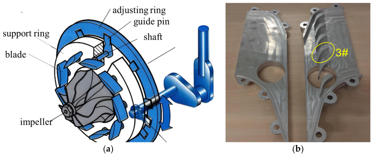
The radial turbine is a critical component for power generation. It is widely utilized in various energy transmission and transformation systems, thereby varying significantly in shape, structure, and size. Nowadays higher-performance radial turbines are in demand due to more stringent regulations on environmental protection [1,2,3], particularly for the variable nozzle turbine (VNT), which is extensively employed in internal combustion engines to enhance the power and fuel economy of vehicles and aircraft. Consequently, a thorough investigation into the mechanisms of performance degradation is essential for further improving VNT performance. It is generally known that the clearance between components in a turbine is an important factor that affects the turbine performance. In a VNT, clearances exist not only at the impeller tip but also at both ends of the variable nozzle vane. This is necessary to allow the vane opening to be adjusted freely, as shown in Figure 1. Typically, the total clearance at both ends of the nozzle vane accounts for approximately 2–4% of the vane height, which produces a strong tip leakage flow.
The literature indicates that leakage flow induces numerous negative effects on turbomachinery. Wang et al. [4] studied the unsteady tip leakage flow in a centrifugal compressor impeller and identified it as a potential reason for rotating instability. Mirzai et al. [5] also investigated the role of tip clearance flow in the instability phenomenon of centrifugal compressors and found that the tip leakage flow does indeed cause instability in the compressor. Furthermore, the tip leakage flow is found to increase flow losses, resulting in significant degradation of turbine efficiency [6,7,8]. Consequently, numerous experimental and numerical investigations have been conducted to elucidate the mechanism of how the tip leakage flow affects efficiency, flow losses, and heat transfer characteristics [9,10,11]. Various geometric configurations have been investigated in these studies, including full turbine models, partial turbine models, and plane cascades. So far, improving turbine performance by controlling tip leakage flow remains a critical research topic in turbomachinery. Pan et al. [12] studied the influence of tip clearance distribution on blade excitation of a vaneless radial turbine using numerical method; the results suggest that the blade vibration responds nonlinearly to meridional tip clearance variations. Ketata et al. [13] investigated the effect of the blade number on performance and loss generation within a radial turbine of a small-scale turbocharger, and the research revealed that the leakage flow through the clearance gap of the turbine was correlated to the number of blades.
For the VNT nozzle vane, the nozzle vane opening can significantly affect the tip leakage flow characteristics [14]. Hideaki et al. [15,16] found that leakage flow is enhanced at small openings due to the increased pressure difference between the pressure and suction sides. Hu et al. [17] showed that turbine efficiency at the minimum opening is 5% lower than that at the maximum opening. Additionally, the inlet flow of a VNT often exhibits pulsating characteristics, leading to fluctuations in the expansion ratio. Numerical studies by Lei and Qi [18,19] have shown that increasing expansion ratio gradually strengthens the tip leakage flow, thereby increasing leakage losses. Compared with the nozzle opening and expansion ratio, clearance size is a more crucial factor to the leakage flow, since it can significantly change the tip leakage flow pattern and the losses through its interaction with the main flow. Hu et al. [20] showed that the turbine efficiency decreases with the increase in the nozzle vane tip clearance within a certain range. When the tip clearance increases to a certain size, the turbine efficiency is no longer increasing at larger tip clearance. Moreover, it is demonstrated that the nozzle vane tip clearance can also affect the flow rate of the turbine.
Meanwhile, VNTs operate in high-temperature environments for extended periods, leading to thermal deformation of the nozzle vane. This deformation results in different clearance size at the two ends of the vane due to the unevenly distributed temperature along the length of the vane [21,22]. On the other hand, long-term operation exposes the turbine to corrosion, wear, machining errors, and assembly tolerances. Consequently, the tip clearance may be unevenly distributed along the chord direction of the vane [23].
Such non-uniformity significantly influences the flow pattern and aerodynamic performance, yet it has been rarely investigated. Therefore, it is essential to specifically investigate the effects of non-uniform clearance distribution on turbine performance.
Notably, non-uniform clearance profiling is a potential method for reducing flow losses and improving aerodynamic performance. Many researchers have used the non-uniform clearance profile to improve the compressor efficiency and achieved remarkable results [24,25,26,27,28]. These efforts provide a valuable reference for the research of turbine in terms of how to reduce the tip leakage-induced flow losses and improve the turbine efficiency. Therefore, some researchers investigated the flow characteristics of axial turbines under the influence of non-uniform clearance. Gao et al. [29] carried out a numerical study to investigate the effect of axially non-uniform tip clearance on the aerodynamic performance of an unshrouded turbine stage. Results showed that the shrinking tip clearance enables the interaction between tip leakage flow and passage secondary flow to reduce the total losses in turbines. The experimental work presented by Chen et al. [30] indicated that the expanding clearance with cavity squealer tip can reduce the flow losses at the outlet and improve the aerodynamic performance of the turbine cascade.
However, current research on the influence of non-uniform clearance on turbines is focused on axial turbines, whilst less attention has been paid to VNTs, particularly for supersonic VNTs, where the flow field is more complex due to shock waves. Shock wave is a critical phenomenon in VNTs [31,32,33], significantly impacting performance [34] and structural integrity [35,36,37]. In this case, the non-uniform clearance not only affects leakage flow patterns but also interacts with shock waves. Previous investigations [20,38,39] have shown that the interaction between tip leakage flow and shock wave has significant impacts on the turbine performance.
In summary, research on the effects of non-uniform clearance on turbine performance remains insufficient. First, most studies have focused on axial turbines and compressors, whereas the tip leakage in VNT guide vanes is more pronounced, yet relevant research is extremely scarce. Second, the flow field in supersonic VNTs involves complex shock structures, and it remains unclear how non-uniform clearance affects the shock wave morphology and the shock–leakage vortex interaction mechanism through alterations in the leakage vortex. In addition, existing studies lack systematic comparisons of the aerodynamic performance between different non-uniform clearance profiles, namely converging and diverging types.
To address these shortcomings, this paper employs a three-dimensional numerical simulation approach, taking the nozzle guide vane of a transonic VNT as the research object. A linear cascade model geometrically consistent with the vane and a full radial turbine model are established to systematically investigate the flow field characteristics under three clearance profiles: uniform clearance (UC), expanding clearance (EC), and shrinking clearance (SC). The study focuses on the flow losses induced by tip leakage, the interaction between tip leakage flow and shock waves, and the effects of non-uniform clearance on supersonic VNT performance. This research will reveal the relationship between non-uniform clearance and supersonic VNT performance, thereby providing a theoretical basis for developing new methods to enhance the aerodynamic performance of VNTs.

2. Methods

2.1. Radial Inflow Turbine System

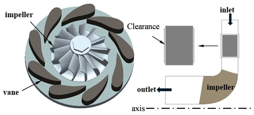
The radial inflow turbine system investigated in the present paper is shown in Figure 2a, including a radial inflow turbine with a variable nozzle and a plane vane cascade. The system specifications are listed in Table 1 and Table 2.
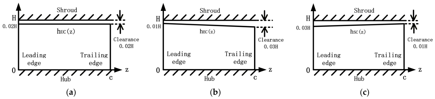
The plane vane cascade (Figure 2b) is derived from the nozzle vane of the turbine system. It should be noted that only one vane (3#) is designed with clearance, and the other vanes have no clearance. To study the tip leakage flow characteristics in tip region with the non-uniform clearance, three different tip clearances are designed in this paper. The tip clearance size for the uniform clearance (UC) case is equal to 2% of the vane span. For the expanding and shrinking clearances, their sizes both increase linearly from 1% to 2% of the vane span from one end to the other end but at opposite directions. The reason for such designs is to maintain the same leakage area for different clearance shapes, as shown in Figure 3.
To avoid ambiguity in definition, the non-uniform clearance profiles in this paper are specified as follows. The coordinate axis z is taken along the vane axial chord direction, with the origin z = 0 set at the leading edge (LE) and z = c at the trailing edge (TE), where c denotes the axial chord length. The clearance height h(z) is expressed as a percentage of the vane span height H. The mathematical expressions for the three clearance profiles h(z) are given as follows:
h U C ( z ) = 0.02 H , 0 z c ,
h E C ( z ) = 0.01 + 0.01 · z / c H ,
h S C ( z ) = 0.02 0.01 · z / c H ,
To ensure that the total leakage areas of the three schemes are strictly equal and to eliminate the influence of differences in total leakage on the results, the three profiles must satisfy the following integral constraint:
0 c h U C ( z ) d z = 0 c h E C ( z ) d z = 0 c h S C ( z ) d z = 0.02 H c ,
This constraint ensures that the EC and SC profiles have exactly the same leakage area as the uniform clearance (UC). Furthermore, the above chordwise gap distribution is applied simultaneously and consistently to both the hub and casing end walls of the vane to ensure flow symmetry.
In this paper, two computational models are employed: a full radial turbine model, which is used to obtain overall performance parameters and to validate against experimental data, and a linear cascade model, which is used for mechanistic investigations of flow details, including leakage vortex structures, shock wave morphology, and loss distributions. The linear cascade is obtained by unwrapping a single nozzle guide vane from the full turbine along the circumferential direction; its vane profile parameters are identical to those of the corresponding vane in the full turbine, and its geometry is relatively simple, facilitating grid refinement and visualization. This allows for a clearer capture of the physical essence of the tip leakage–shock interaction. Consequently, all subsequent results and analyses are based on the linear cascade model. The combined use of the two models enables mutual corroboration between the revealed flow mechanisms and the evaluated overall turbine performance, thereby providing a better understanding of the effects of non-uniform clearance on the VNT [19].
It should be added that comparative studies [40] between plane cascades and annular rotating cascades have shown that, despite quantitative differences (e.g., in leakage mass flow and loss magnitude), the qualitative characteristics of the flow structures are transferable—that is, even when rotational effects are excluded, the flow structures in plane cascades and annular cascades still exhibit similarities. This indicates that the flow physics revealed by plane cascade studies remain relevant for rotating conditions.
In summary, although quantitative differences do exist between the plane cascade and the actual rotating configuration—for instance, in leakage mass flow rate and vortex strength—these differences do not affect the core qualitative conclusions of this study. The plane cascade setup allows us to isolate the rotational effects and thus reveal more clearly the fundamental laws governing the influence of different clearance profiles on flow characteristics—and this precisely defines the methodological positioning of the present work.

2.2. Numerical Method

The ICEM module in ANSYS (Ansys19.0, Canonsburg, PA, USA) is used to generate structured grids in the fluid domain, including the vane channel grid and the clearance grid. An O-type grid is adopted around the vane, and an H-type grid is adopted for the remaining parts. To better analyze the flow in the boundary layer region, the y+ value is kept below 3 to ensure the first grid node is located within the viscous sublayer. Moreover, the grids of the tip clearance region and the shock wave generation region are refined to accurately model the interaction between the tip leakage flow and the shock wave.
The CFX package in ANSYS (Ansys19.0, Canonsburg, PA, USA) is used to solve the 3D steady Reynolds-averaged Navier–Stokes (RANS) equations. The boundary conditions are set as follows: the simulation uses pressure-inlet and pressure-outlet, total pressure and total temperature are specified to 0.2 MPa and 350 K at the inlet respectively, and the average static pressure is imposed at the outlet. All walls are specified as adiabatic and no-slip conditions. The k-ω turbulence model is adopted in this paper because it can accurately predict the boundary layer separation under adverse pressure gradients. Turbulence intensity is set to a medium level (5%). The solution method is set to a high-resolution scheme. The convergence control uses an automatic time scale, and RMS residual is less than 1 × 10⁻⁵.
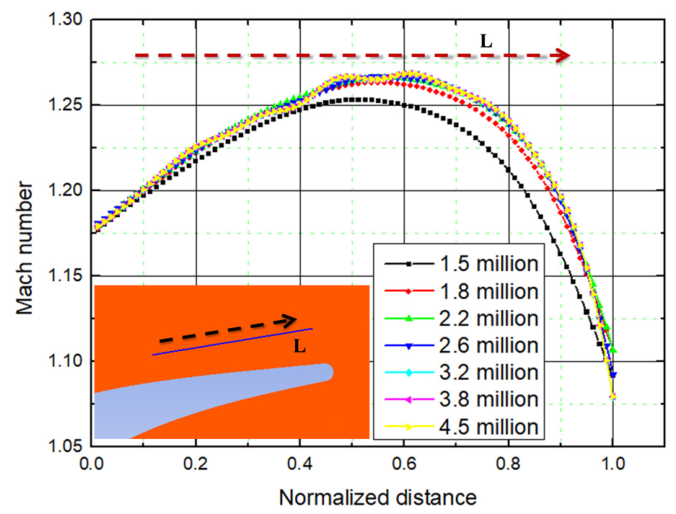
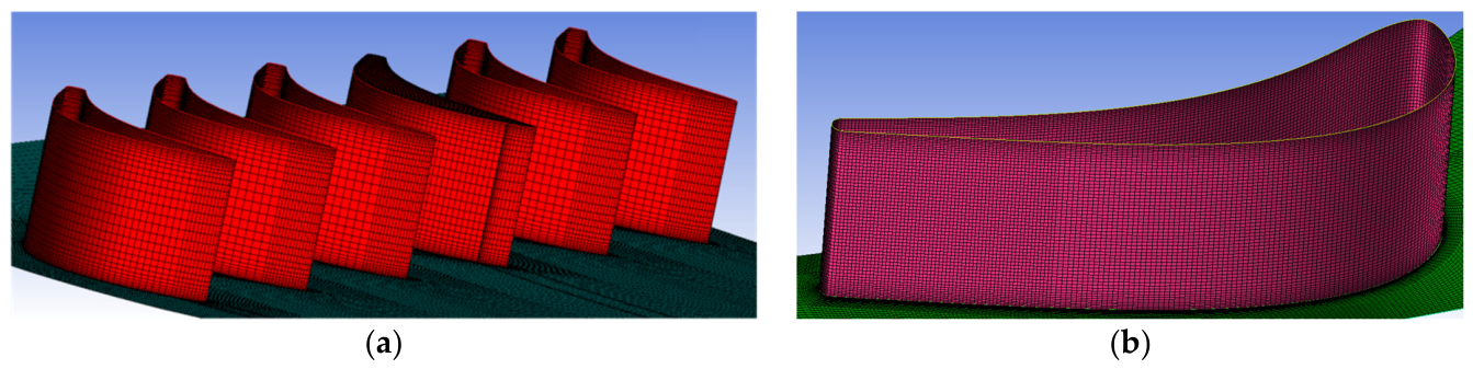
The grid number has a significant influence on precision of the modeling results, especially for the tip leakage flow and shock waves. Therefore, a grid independence study is carried out on the uniform clearance using the grid number of 1.5, 1.8, 2.2, 2.6, 3.2, 3.8 and 4.5 million. The mesh topology and distribution laws for each grid are similar, with the main difference in the refinement level of the grid. During the grid independence study, the boundary conditions at the inlet and outlet were kept consistent. Figure 4 shows the Mach number distribution on the line L with different grid numbers. The L line in the figure acts as the reference benchmark for Mach number, which is utilized to verify the convergence of numerical simulation results under varying mesh densities. When the number of grid reaches 3.2 million or more, the Mach number remains unchanged, indicating that grid independence has been achieved. Consequently, the mesh configuration with 3.2 million grids is used for in this paper. The computational domain and a zoom-in view of the inner mesh are shown in Figure 5.

2.3. Validation of Numerical Method

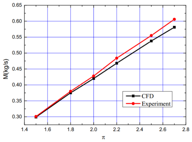
When the static pressure at the nozzle vane outlet is constant, the mass flow rate of the nozzle vane at different expansion ratio π (defined as the ratio of inlet total pressure to outlet static pressure) can be obtained by changing the total pressure at the nozzle vane inlet. By comparing the experimental and numerical mass flow rates, the validity and accuracy of the numerical method can be verified. All the mass flow rate data at different expansion ratios are shown in Figure 6. At all expansion ratios, the mass flow rates obtained by experiments and modeling exhibit a minimal difference, with a maximum error of less than 4.1%. The reason for the error has been explained in detail by Lei [33]. Therefore, it demonstrates that the numerical method used in this paper can precisely predict the flow field in turbine nozzle. To further validate the numerical simulation method, we cite relevant contents from previously published articles as corroborating evidence.
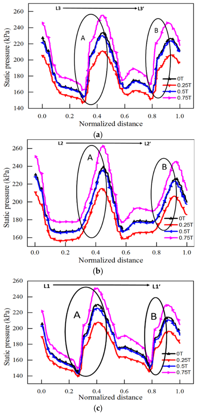
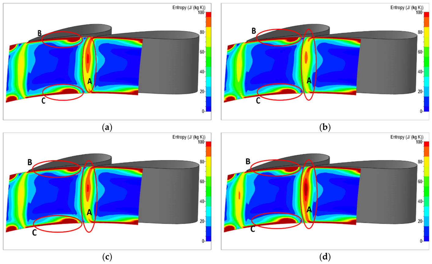
The internal flow in turbomachinery is inherently periodic and unsteady, and this unsteady behavior becomes particularly pronounced under transonic conditions. Reference [18] presents an analysis of the flow field characteristics within a turbine under pulsating inlet conditions. As shown in Figure 7 and Figure 8, the unsteadiness does have a non-negligible impact on the flow structures. Under the specific operating conditions and geometric parameters considered in this study, although the instantaneous flow field exhibits significant unsteady features—such as leakage vortex wandering and shock oscillation—these unsteady fluctuations have a relatively limited effect on the time-averaged performance metrics, including the total pressure loss coefficient and efficiency. Steady numerical simulations can capture, to a certain extent, the principal features of the time-averaged flow field and the overall trend of aerodynamic performance. Therefore, the use of a plane cascade configuration together with a steady analysis approach to investigate the mechanisms and trends of the influence of different clearance profiles on the time-averaged aerodynamic performance within the vane passage remains of considerable reference value, within the applicable scope of the methodology.

3. Results and Discussion

3.1. The Flow Losses in Nozzle Vane

For the VNT, clearances exist not only at both ends of the nozzle vane but also at the tip region of the rotor blade. Driven by lateral pressure gradient, the VNT produces strong and complex tip leakage flows, which can result in significant flow losses and turbine performance degradation. Early research by Lei [41] has indicated that the nozzle vane clearance plays a significant role in the performance degradation of the turbine compared to the rotor clearance. These facts indicate that mitigating the tip leakage flow of the nozzle vane is an effective way to improve the aerodynamic performance of the VNT. Therefore, this paper mainly focuses on the influence of non-uniform clearance on the nozzle vane tip flow of the plane cascade in order to find a potential way to improve VNT aerodynamic performance.
In this section, the tip leakage-induced flow losses in the plane cascade under the effect of non-uniform clearance are investigated in detail. Since the clearance size has a great influence on the leakage mass flow rate and consequently impacts the leakage flow losses, the leakage mass flow rate with different tip clearance profiles is studied firstly to analyze the influence of non-uniform clearance on the flow losses.
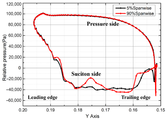
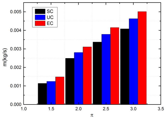
To quantitatively analyze the influence of non-uniform clearance, the leakage mass flow rates for three tip clearance profiles are compared as shown in Figure 9. The leakage mass flow rate increases gradually with the increase in expansion ratio for all three clearance profiles. However, at the same expansion ratio, the leakage mass flow rate varies significantly for the different tip clearance profiles. It is shown that the leakage mass flow rate of the UC profile is larger than that of the SC profile but smaller than that of the EC profile, which can be attributed to the variable pressure difference between the two sides of the vane. Figure 10 shows the static pressure distribution curves at two span locations near the end of the vane to explore the variation in leakage mass flow rate with different clearance profiles. The vanes studied in this paper are rear-loaded, and the magnitude of the lateral pressure gradient on both sides of the vane is larger near the trailing edge of the vane compared with that near the leading edge. Therefore, the leakage mass flow rate is larger when the clearance size near the trailing edge of the vane is larger. For the case of SC, it features a larger tip clearance size near the leading edge and a smaller tip clearance near the trailing edge. Therefore, the leakage mass flow rate of the SC profile is the smallest among all the tip profiles.
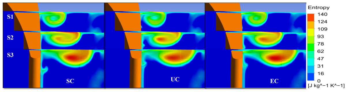
Since the tip leakage-induced flow losses will result in an increased entropy, the entropy distribution can be used as a measurement of the leakage flow losses. The entropy contours at three sections for all the tip clearance profiles are shown in Figure 11. The sections are on planes perpendicular to the chord of the vanes and labeled as “S1”, “S2” and “S3”. From the leading edge to the trailing edge, the peak value and the area of high-entropy region on the section planes increase gradually due to the gradual development and expansion of the tip leakage vortex. The influence of non-uniform clearance on leakage vortex is quite different with different clearance profiles. At the beginning of the tip leakage vortex (section S1), the area of high-entropy region of the SC case is slightly larger than that in other clearance cases due to the larger tip clearance size near the leading edge. With the development of tip leakage vortex, the entropy peak value in the EC case is the highest among the three tip clearance profiles at section S2, whilst the entropy peak value of the SC case is lowest. Near the trailing edge, the area of high-entropy region in the SC case is smaller than that of other cases at section S3. It can be roughly inferred that the case of SC can reduce the leakage flow losses compared with the UC case and the EC case.
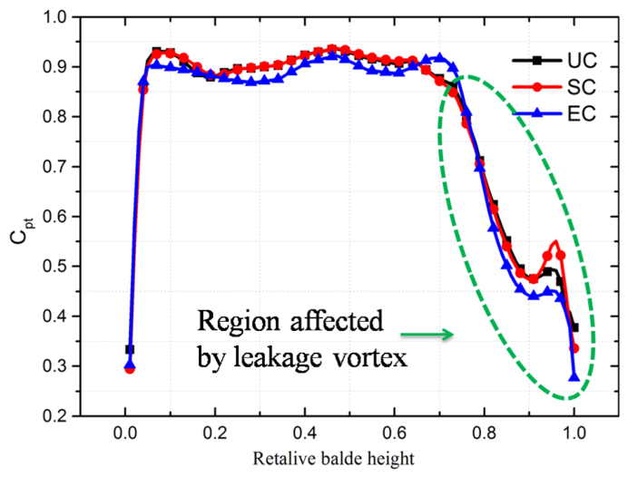
To further explore the influence of non-uniform clearance on the flow losses in nozzle vane, the pitch-averaged total pressure coefficient Cpt along the vane span at vane outlet for the three tip profiles are compared and presented in Figure 12. The Cpt is defined as follows:
C p t = P t , e x i t P s , e x i t P t , i n l e t P s , e x i t ,
where P t , e x i t is the total pressure at outlet; P s , e x i t is the static pressure at outlet; P t , i n l e t is the total pressure at inlet.
It can be seen that the pitch-averaged Cpt reaches a high level from 0.05 to 0.7 vane spans, and then drops rapidly from 0.7 to 1 vane span. According to the definition of total pressure coefficient, the low Cpt means high flow losses. For the three tip profiles, the low Cpt is mainly located at the tip region of the vane cascade. Combined with the entropy contours in Figure 11, it indicates that the tip leakage flow is the main secondary flow in vane cascade which dominates the entire flow field. Therefore, the flow losses in the vane passage are mainly caused by the tip leakage flow. Comparing the three clearance profiles, the pitch-averaged Cpt of the SC case is basically the same as that of the UC case from about 0 to 0.9 vane span. At the region from about 0.9 to 1.0 vane span which is also the core region of the tip leakage vortex, the pitch-averaged Cpt of the SC case is larger than that of other cases. Meanwhile, the pitch-averaged Cpt of the EC case is the smallest among all the cases except at 0.7 vane span. It means that the SC profile has smaller flow losses than other clearance profiles. Combined with the result of Figure 9, we can find that the leakage mass flow rate of the SC case is the smallest among the three tip profiles, which weakens the negative effect of the tip leakage vortex and thus reduces the flow losses, as explained in [29]. Therefore, it can be further concluded that the case of SC can improve the tip flow behavior and the aerodynamic performance in the turbine vane cascade.

3.2. The Effect of Non-Uniform Clearance on Tip Leakage Flow Pattern

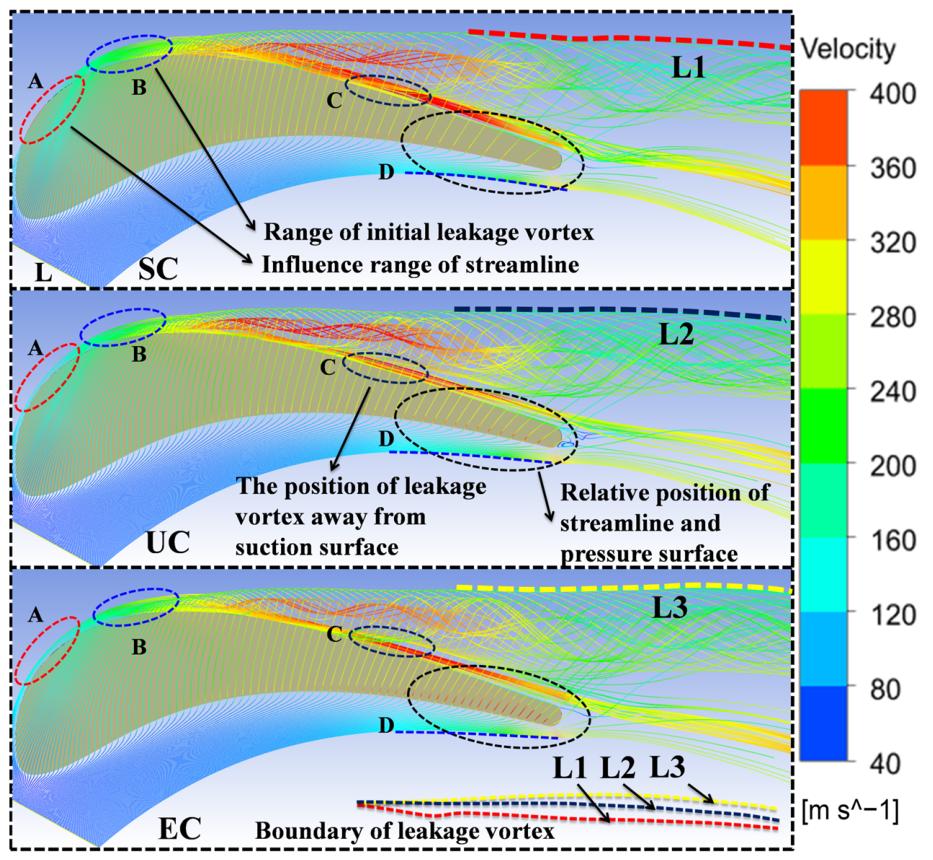
The two factors for the generation of the tip leakage flow are the lateral pressure gradient and the tip clearance geometry. When the pressures at the inlet and outlet remain constant, the lateral pressure gradient remains unchanged. Therefore, the clearance size is the predominate factor that affects the tip leakage flow pattern given fixed vane opening. Figure 13 shows the 3D streamline starting from line L with different clearance profiles. The 3D streamline shows an obvious tip leakage vortex formed by the interaction between the tip leakage flow and the main flow. The tip leakage vortex initiates at the location of about 20% chord length from the leading edge, and it deviates from the suction surface at about the middle of the chord. In addition, the main flow near the suction surface is squeezed by the tip leakage vortex at the bottom of the leakage vortex, which flows downstream along the suction surface.
Comparing the 3D streamlines of the three clearance profiles, it can be found that the tip leakage vortices have similar patterns for all the clearance profiles but different characteristics at specific locations. In the front part of the vane tip, with increasing tip clearance size, the streamline is gradually moved to the suction surface, as shown in region A. The size of initial leakage vortex of the SC case is larger than that of the other cases, as shown in region B. Meanwhile, the initial positions of the leakage vortex for all the clearance cases are nearly the same. In the middle part of the vane tip, the streamline velocity of the leakage vortex core has changed significantly. The case of SC has the largest streamline velocity among the three tip profiles, while the streamline velocity of the EC case is significantly reduced compared with the SC case, and the position of the leakage vortex streamline of EC case is moved further away from the suction surface. Comparing with the results of all the tip schemes, the leakage vortex streamline of the EC case separates from the suction surface firstly, whilst the leakage vortex streamline of the SC case is the last one to separate from the suction surface, as shown in region C. In the rear part of the vane tip, when the clearance size at the trailing edge is increased, the flow velocity in the tip clearance is notably increased, and the streamline in the main flow passage moves towards the pressure surface, as shown in region D. Particularly, the separation lines of the leakage vortex gradually deviate from the suction surface, which means that the area influenced by the leakage vortex gradually increases with the increasing clearance size at the trailing edge. In other words, the influence range of the leakage vortex of the EC case is the largest at the trailing edge region of the vane (as shown by L3), while the case of SC has the opposite behaviors (L1).
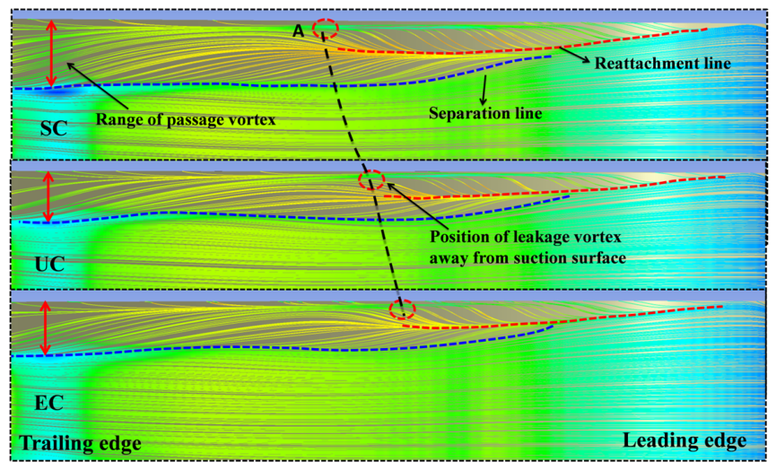
To further study the influence of non-uniform clearance on tip flow field of the nozzle vane, the limiting streamlines on the suction surface with different clearance profiles are presented in Figure 14. The limiting streamline at the top of the vane suction surface changes dramatically due to the interaction between the tip leakage flow and the boundary layer. The change and development of the limiting streamline can reflect the vortex structure at the top of the vane. An obvious reattachment line and separation line are observed on the suction surface due to the influence of the leakage vortex, as shown by red dotted lines and blue dotted lines in the figure, respectively. The reattachment line is correlated to the tip leakage vortex, while the separation line is correlated to the passage vortex. The vane performance is deteriorated due to the interaction of complex vortex system, resulting in increased flow losses in vane tip region. Meanwhile, the vortexes also have a significant impact on the downstream flow field. The reattachment line of the SC case is further away from the vane tip and it is longer than those of the other cases, compared with the other two cases. It means that the tip leakage vortex caused by the SC case is larger in the front part of the vane, and the development distance of the leakage vortex along the suction surface is longer than that in the other cases. Combined with the 3D streamline, we give the location where the leakage vortex deviates from the suction surface, as shown in the red circle in Figure 14. For the case of SC, the location of the leakage vortex separating from the suction surface is closer to the trailing edge of the vane than that in the other clearance cases. In contrast, the leakage vortex of the EC case is the smallest in the front part of the vane and it is separated from the suction surface earliest among all the clearance cases. In addition, the separation line of the SC case is further away from the vane tip compared with the other two cases, probably because the passage vortex of the SC case is the biggest in the span direction among the three tip profiles.
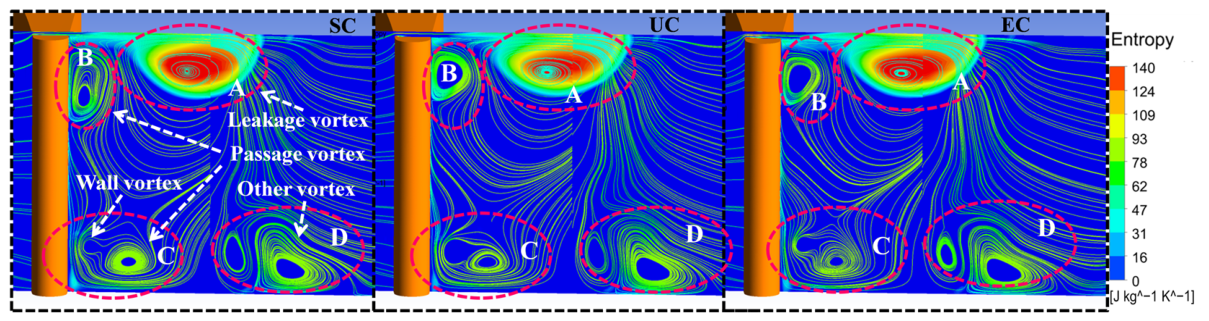
Figure 15 shows the vortex structure on the sectional plane near the exit of trailing edge vane for all the tip profiles, which provides a basis for further research of flow pattern within the vane cascade. It can be seen that a very complex vortex system is produced at the exit of the vane. The vortex system includes tip leakage vortex, passage vortex, and wall vortex etc. The tip leakage vortex is in the middle of the vane top, which is the biggest among all the vortices, as shown in region A. Due to the extrusion of the leakage vortex, the passage vortex is located between the leakage vortex and the suction surface, as shown in region B. Meanwhile, there is also a passage vortex at the bottom of the suction surface of the vane. It is worth noting that there is a small wall vortex beside the passage vortex in region C. The wall vortex is located above the passage vortex, which forms a new vortex pair with the passage vortex. In addition, another pair of vortices is generated in region D, which is mainly caused by the interaction between the end-wall boundary layer, wake and shock wave. Although many vortices are generated in the flow field, it can be seen from the entropy contour at the exit section that the tip leakage vortex is dominant in the vortex system, which leads to larger flow losses than the other vortexes. Comparing the three clearance profiles, the leakage vortex of the SC case is the smallest among them, and the region of high entropy is lowest. Therefore, it indicates that the flow losses of the SC case are the smallest among the three cases.
Based on the above analysis, we can conclude that when the clearance size in front part of the vane is increased, the initial tip leakage vortex becomes larger. However, in the initial stage of the leakage vortex development, the vortex strength is small and thus the flow losses caused by leakage vortex is small. With the development of tip leakage vortex, the range and intensity of the leakage vortex increase gradually, which leads to increased flow losses. Especially at the rear part of the vane tip, with the increase in the clearance size, the clearance jet flow is significantly augmented due to the large lateral pressure gradient of the rear-loaded vane. The clearance jet flows wrap around the leakage vortex, which further increase the range and strength of the leakage vortex. As a result, the negative effect of the leakage vortex is augmented, resulting in large flow losses.

3.3. The Interaction Between Tip Leakage Flow and Shock Wave

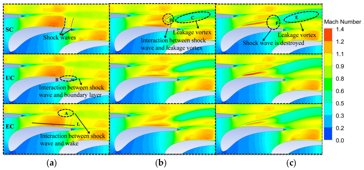
For the transonic or supersonic nozzle vane, a strong shock wave is easily generated at the suction surface near the trailing edge. Previous studies have shown that the interaction between the shock wave and the leakage vortex can significantly change the flow field. As described above, the flow pattern of tip leakage flow is changed significantly with non-uniform clearance profiles. Therefore, when the tip leakage flow changes, the interaction between shock wave and tip leakage flow becomes more complicated. To compare and analyze the interaction between the leakage flow and the shock wave with non-uniform clearance profiles, the Mach number contours at different vane span sections are shown in Figure 16. At 50% vane span (Figure 16a), a strong (first) shock wave and a weak (second) shock wave are produced near the trailing edge on the suction side. The strong shock wave interferes with the wake of the adjacent vane, resulting in the increase in the wake range, as shown in region A. At the same time, the interaction between strong shock wave and boundary layer increases the thickness of boundary layer after shock wave, as shown in region B. At the 80% vane span section (Figure 16b), an obvious tip leakage vortex can be observed in region C. The tip leakage vortex interferes with the shock wave in region D. Comparing the section at 50% span with that at 80% span, the shock wave pattern is significantly different due to the influence of the tip leakage vortex. The structure of the first strong shock wave is substantially changed and bent toward the reverse direction of the leakage flow, and the second weak shock wave has almost disappeared. With the increase in the vane span, for example, at 90%of the span section (Figure 16c), the range of the leakage vortex is further increased in region E, and the shock wave is significantly affected by the tip leakage vortex, which leads to more significant change in shock wave structure, as shown in region F. This kind of disordered shock wave structure is likely to induce significant flow losses.
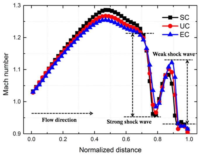
For all the tip profiles, the patterns of shock wave are overall similar except for some differences in specific regions. Figure 17 illustrates the Mach number distribution on the line L (shown as in Figure 16) at 50% vane span for all clearance cases. It is seen that the Mach number gradually increases from subsonic to supersonic along the flow direction until shock wave is encountered, when the Mach number begins to drop rapidly. We can clearly see that there are two shock waves in the flow field, a strong shock wave and a weak one. Comparing the three tip clearance profiles, the reduction in Mach number in the SC case is the largest for them at the location of the strong shock wave, while that in the EC case is the smallest, because the first shock wave in the SC case is the strongest. However, the reduction in Mach number of the SC case is the smallest for all the clearance cases at the location of weak shock wave, while the that in the EC case is the largest. This is because the second shock wave is the strongest in the EC case. In addition, the location of the shock wave of the SC case moves slightly towards the leading edge compared to other cases, which is caused by the different degree of the leakage vortex squeezing the main flow.
At 80% vane span (Figure 16b), it can be found from the Mach number contours that the influence of tip leakage vortex on shock wave pattern of the SC case is weaker than that on other clearance cases due to the higher intensity of shock wave. At 90% vane span (Figure 16c), the structure of shock wave is distorted significantly, so the difference in the contours is negligible between all three clearance profiles. However, the location of the interaction between the shock wave and the leakage vortex moves towards the leading edge with the increased clearance size at the trailing edge region. In addition, the high Mach number can be seen in the middle of the leakage vortex in front of the shock wave, which also proves the analysis for Figure 13.
According to the above analyses, we obtain a conclusion that the shock wave is significantly affected by the interaction between the tip leakage vortex and the shock wave. Comparing with the velocity streamline of the leakage flow before and after the shock wave, as shown in Figure 13, it can be found that the velocity of the tip leakage vortex decreases greatly due to the influence of shock wave, which means that the shock wave has a great influence on the tip leakage vortex.
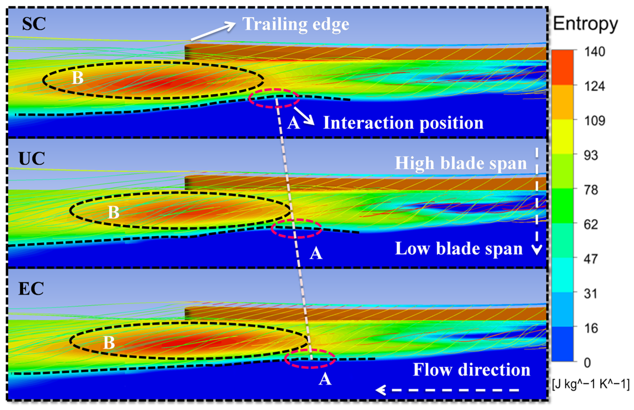
To further investigate the effect of the shock wave on the tip leakage vortex, Figure 18 shows the streamlines of the leakage vortex and the entropy contours. At the location where the shock wave interferes the tip leakage vortex, the tip leakage vortex core diameter is reduced dramatically, as shown in region A. In addition, the entropy at the leakage vortex core behind the shock wave increases significantly, as shown in region B. The reason is that when the shock wave interferes the leakage vortex, the leakage vortex expands and breaks down, which leads to a notable increase in flow losses. This expansion of the vortex core is caused by the reverse pressure gradient produced by the shock wave. In addition, the losses caused by the interaction between the shock wave and the leakage vortex are much greater than those caused by the leakage vortex alone. Comparing the result of all clearance profiles, from the high-entropy location, it suggests that the location of the interaction between shock wave and leakage vortex in the SC case is closer to the trailing edge than that in the other clearance cases, while the case of EC is far away from the trailing edge.
In summary, the interaction between shock wave and tip leakage vortex is the main reason for the large flow losses in nozzle vane, which has a much greater effect than the interaction between tip leakage flow and main flow. The interaction between shock wave and tip leakage vortex is affected by many factors, such as the influence range and intensity of the tip leakage vortex, the location and intensity of the shock wave and so on. In the case of non-uniform clearance, it is more complicated due to the changes in the patterns of the leakage vortex and the shock wave. For the SC case, the mass flow rate of the clearance jet flow and the strength of the leakage vortex are small, which leads to the minimum flow losses caused by the interaction between the shock wave and the leakage vortex. Therefore, the flow losses of SC case are smaller than that of the other cases.

3.4. The Effect of Non-Uniform Clearance on Aerodynamic Performance of VNT

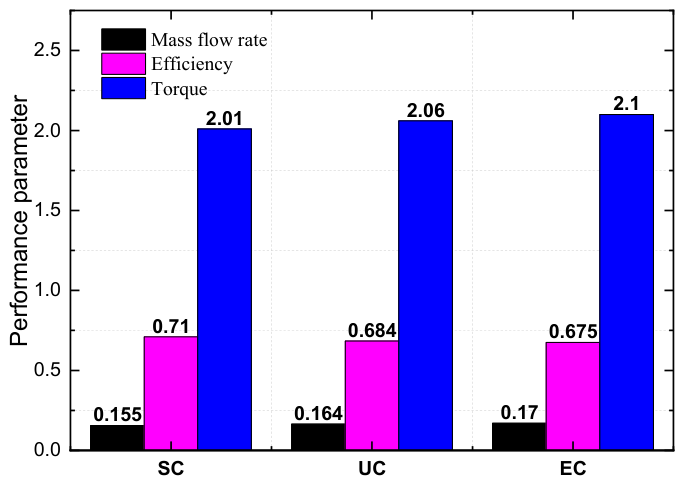
According to aforementioned context, we can conclude that the SC case can mitigate the tip leakage flow and the associated flow losses in flow field of the nozzle vane. To further investigate the influence of non-uniform clearance on the aerodynamic performance of the VNT, three main performance parameters are shown in Figure 19. It can be seen that the different clearance profiles can significantly affect the flow capacity of the turbine.
According to the analysis in Section 3.1, for the post-loaded vane configuration, the transverse pressure gradient near the vane trailing edge is much greater than that at the leading edge. Therefore, the size of the trailing edge gap plays a dominant role in the leakage flow. Since the EC scheme has the largest trailing edge gap, it results in the maximum leakage mass flow rate. The resulting tip leakage vortices are the strongest and most extensive, interacting most intensely with the shock wave’s destructive power. Thus, the flow loss is the greatest and the efficiency is the lowest. On the contrary, the SC scheme has the smallest trailing edge gap, fundamentally limiting the scale of the leakage flow and weakening the intensity of the leakage vortices and their interaction with the shock wave. As a result, while slightly sacrificing the flow capacity, it significantly reduces the flow loss and achieves the highest aerodynamic efficiency.
In addition, the torque is also different with different clearances. The torque of EC case is approximately 4.5% higher than that of SC case.
The difference in torque is the result of the combined effect of efficiency and mass flow rate: although the EC scheme has the lowest efficiency, its larger mass flow rate provides a higher total momentum input to the turbine rotor, which partially offsets the efficiency loss and leads to its torque ultimately being slightly higher than that of the SC scheme.
From the above analysis, it can be concluded that the non-uniform clearance has a significant impact on the aerodynamic performance of the VNT, and the SC profile can significantly improve the thermal efficiency of the VNT. It should be noted that there are pulse fluctuations in the inlet pressure of the turbine, which leads to variable turbine expansion ratios. When the expansion ratio changes, the leakage vortex and the shock wave fluctuate periodically. The intensity and locations of the tip leakage vortex and the shock wave with non-uniform clearance also change significantly. Therefore, the effect of expansion ratio on the interaction between the shock wave and the leakage vortex with non-uniform clearance should be further investigated in the future, so as to understand the flow characteristics in the tip region of the nozzle vane under pulsating inlet conditions.

4. Conclusions

In this paper, the influence of non-uniform clearance on the flow field pattern in a vane cascade and aerodynamic performance of a supersonic turbine has been thoroughly investigated by numerical simulation. Three tip clearance profiles, including two non-uniform clearances and one uniform clearance, were used in the vane cascade. The effect of non-uniform clearance on mass flow rate, flow losses, leakage flow pattern, the interaction between the shock wave and the leakage vortex, as well as the aerodynamic performance of the VNT, were studied in detail. The main conclusions can be summarized as follows:
  • For the rear-loaded vane profile, due to the large lateral pressure gradient on both vane sides, the SC case has the smallest leakage mass flow rate, the largest pitch-averaged Cpt at the vane outlet and the smallest flow losses among the three tip clearance cases. Meanwhile, the initial size of leakage vortex for the SC profile is the largest in leading edge region of the vane. However, the area influenced by the leakage vortex for the SC case is the smallest at the trailing edge region of the vane. The location of the leakage vortex separation in the SC case is the closest to the trailing edge of the vane. This indicates that for rear-loaded turbine vanes, designing the clearance to converge toward the trailing edge can effectively reduce the leakage flow driven by the high-pressure region at the trailing edge, thereby reducing tip clearance losses at the source. This design strategy does not require altering the vane profile or increasing manufacturing complexity, and thus offers a simple and feasible direction for clearance optimization in engineering practice.
  • The shock wave pattern is significantly altered due to the influence of the tip leakage vortex. For the first (strong) shock wave, the SC case exhibits the strongest shock wave, and the influence of the tip leakage vortex on the shock wave pattern is the weakest. The location of the interaction between the shock wave and the leakage vortex in the SC case is the closest to the trailing edge. The location of the shock–vortex interaction near the trailing edge indicates that the leakage vortex maintains a relatively well-organized structure over a longer chordwise distance, thereby avoiding premature vortex breakdown and extensive mixing losses. This suggests that in engineering design, the tip leakage should be controlled as close to the leading edge as possible, so as to mitigate the interference of the leakage vortex with the downstream shock structure.
  • The interaction between the shock wave and the tip leakage vortex is the primary source of the large flow losses in the nozzle vane, which dominates the losses caused by the interaction between the tip leakage flow and the main flow. This finding revises the conventional understanding that “mixing between leakage flow and mainstream dominates the losses.” For supersonic VNTs, designers should prioritize suppressing shock–vortex interaction as the core objective of performance optimization, rather than merely focusing on reducing the leakage mass flow rate. This provides a clear theoretical direction for the future development of active/passive flow control techniques.
  • The non-uniform clearance can significantly affect the aerodynamic performance of the VNT. Compared with the EC case, the mass flow rate and torque in the SC case are decreased by 8.8% and 4.3%, respectively. However, the efficiency of the SC profile is 5.2% higher than the EC profile. The performance of the VNT with uniform clearance is intermediate between that of the SC and the EC profiles. The above quantitative results provide a clear performance trade-off basis for clearance selection in turbine design. The SC scheme achieves significant efficiency gains at the cost of a slight reduction in mass flow and torque, making it suitable for applications that prioritize high fuel economy or emission performance, such as automotive turbochargers. Depending on the specific operating conditions, designers can make an optimal trade-off between mass flow and efficiency.

Author Contributions

Resources, X.L.; Writing—original draft, Q.L.; Writing—review & editing, Q.L., C.X., X.L., Z.L. and Z.Z. All authors have read and agreed to the published version of the manuscript.

Funding

This research was funded by [General Scientific Research Project of Hunan Provincial Department of Education] grant number [No. 24C0259].

Data Availability Statement

No new data were created or analyzed in this study. Data sharing is not applicable to this article.

Acknowledgments

The authors sincerely appreciate the financial support from the General Scientific Research Project of Hunan Provincial Department of Education (No. 24C0259). The authors also thank the editors and anonymous reviewers for their constructive comments, which have helped improve the quality of this manuscript.

Conflicts of Interest

Author Xinguo Lei was employed by Wuhan Yuqing Technology Co., Ltd. The remaining authors declare no conflicts of interest.

Abbreviations

The following abbreviations are used in this manuscript:
VNTVariable Nozzle Turbine
UCUniform clearance
ECExpanding clearance
SCShrinking clearance
RANSReynolds-averaged Navier–Stokes

References

  1. Sim, J.-B.; Chang, O.S.; Yook, S.-J.; Kim, Y.W. Partial similarity modeling for the performance of an axial turbine. J. Mech. Sci. Technol. 2024, 38, 5675–5683. [Google Scholar] [CrossRef]
  2. Lim, H.; Choi, B.; Park, M.; Hwang, S.; Park, J.; Seo, J.; Bang, J.; Kim, S.; Lim, Y.; Park, S.; et al. 100-kWe-class supercritical organic Rankine cycle turbine with magnetic bearing for waste heat power generation system. J. Mech. Sci. Technol. 2024, 38, 6621–6633. [Google Scholar] [CrossRef]
  3. Kim, M.; Kim, S.; Kim, D.; Lee, C. Optimization of a nozzle vane of gas turbine pre-swirl system. J. Mech. Sci. Technol. 2024, 38, 2997–3008. [Google Scholar] [CrossRef]
  4. Wang, W.; Yang, C.; Hu, C.; Zhang, H. Investigation of tip leakage flow unsteadiness and rotating instability in a centrifugal compressor impeller. Proc. Inst. Mech. Eng. Part D J. Automob. Eng. 2022, 236, 621–638. [Google Scholar] [CrossRef]
  5. Mirzaee, S.; Zheng, X.; Lin, Y. Improvement in the stability of a turbocharger centrifugal compressor by tip leakage control. Proc. Inst. Mech. Eng. Part D J. Automob. Eng. 2017, 231, 700–714. [Google Scholar] [CrossRef]
  6. Bunker, R.S. Axial turbine blade tips: Function, design, and durability. J. Propuls. Power 2006, 22, 271–285. [Google Scholar] [CrossRef]
  7. Hayami, H.; Senoo, Y.; Hyun, Y.I.; Yamaguchi, M. Effects of Tip Clearance of Nozzle Vanes on Performance of Radial Turbine Rotor. J. Turbomach. 1990, 112, 33–51. [Google Scholar] [CrossRef]
  8. Lattime, S.B.; Steinetz, B.M. High-Pressure-Turbine Clearance Control Systems: Current Practices and Future Directions. J. Propuls. Power 2012, 20, 302–311. [Google Scholar] [CrossRef]
  9. Wheeler, A.P.S.; Korakianitis, T.; Banneheke, S. Tip-leakage losses in subsonic and transonic blade rows. In Proceedings of the ASME 2011 Turbo Expo: Turbine Technical Conference and Exposition, Vancouver, BC, Canada, 6–10 June 2011. GT2011-45798. [Google Scholar] [CrossRef]
  10. Zhang, Q.; O’Dowd, D.O.; He, L.; Oldfield, M.L.G.; Ligrani, P.M. Transonic Turbine Blade Tip Aerothermal Performance with Different Tip Gaps—Part I: Tip Heat Transfer. In Proceedings of the ASME Turbo Expo 2010: Power for Land, Sea, and Air, Glasgow, UK, 14–18 June 2010. GT2010-22779. [Google Scholar] [CrossRef]
  11. Zhang, Q.; O’dowd, D.O.; He, L.; Oldfield, M.L.G.; Ligrani, P.M. Transonic Turbine Blade Tip Aero-Thermal Performance with Different Tip Gaps: Part II—Tip Aerodynamic Loss. In Proceedings of the ASME Turbo Expo 2010: Power for Land, Sea, and Air, Glasgow, UK, 14–18 June 2010. GT2010-22780. [Google Scholar] [CrossRef]
  12. Pan, L.; Yang, M.; Murae, S.; Sato, W.; Shimohara, N.; Yamagata, A. Influence of tip clearance distribution on blade vibration of vaneless radial turbine. Proc. Inst. Mech. Eng. Part D J. Automob. Eng. 2022, 236, 1007–1018. [Google Scholar] [CrossRef]
  13. Ketata, A.; Driss, Z. A numerical study for correlating performance versus number of blades and investigating flow characteristics and loss generation of an automotive radial flow turbine. Proc. Inst. Mech. Eng. Part D J. Automob. Eng. 2022, 236, 1742–1760. [Google Scholar] [CrossRef]
  14. Spence, S.W.T.; O’Neill, J.W.; Cunningham, G. An Investigation of the Flow Field through a Variable Geometry Turbine Stator with Vane Endwall Clearance. Proc. Inst. Mech. Eng. Part A J. Power Energy 2006, 220, 899–910. [Google Scholar] [CrossRef]
  15. Tamaki, H.; Goto, S.; Unno, M.; Iwakami, A. The Effect of Clearance Flow of Variable Area Nozzles on Radial Turbine Performance. In Proceedings of the ASME Turbo Expo 2008: Power for Land, Sea, and Air, Berlin, Germany, 9–13 June 2008. GT2008-50461. [Google Scholar] [CrossRef]
  16. Tamaki, H.; Unno, M. Study on Flow Fields in Variable Area Nozzles for Radial Turbines. Int. J. Fluid Mach. Syst. 2008, 1, 47–56. [Google Scholar] [CrossRef]
  17. Hu, L.; Sun, H.; Yi, J.; Curtis, E.W.; Morelli, A.; Zhang, J.; Zhao, B.; Yang, C.; Shi, X.; Liu, S. Investigation of Nozzle Clearance Effects on a Radial Turbine: Aerodynamic Performance and Forced Response. In Proceedings of the SAE 2013 World Congress and Exhibition, Detroit, MI, USA, 16–18 April 2013. [Google Scholar] [CrossRef]
  18. Qi, M.; Lei, X.; Wang, Z.; Ma, C. Investigation on the flow characteristics of a VNT turbine under pulsating flow conditions. Proc. Inst. Mech. Eng. Part D J. Automob. Eng. 2019, 233, 396–412. [Google Scholar] [CrossRef]
  19. Lei, X.; Qi, M.; Sun, H.; Shi, X.; Hu, L. Study on the interaction of clearance flow and shock wave in a turbine nozzle. In Proceedings of the WCX™ 17 SAE World Congress Experience, Detroit, MI, USA, 4 April 2017. [Google Scholar] [CrossRef]
  20. Hu, L.; Yang, C.; Sun, H.; Zhang, J.; Lai, M. Numerical analysis of nozzle clearance effect on turbine performance. Chin. J. Mech. Eng. 2011, 24, 618–625. [Google Scholar] [CrossRef]
  21. Zhao, B.; Ma, C.; Hu, L.; Yang, C.; Lao, D. Numerical Investigation on Effects of Uncertain Nozzle Vane Clearance on Variable Geometry Radial Turbine Performance. J. Propuls. Technol. 2014, 35, 492–498. [Google Scholar]
  22. Zhao, B.; Ma, C.C.; Hu, L.J.; Yang, C.; Lao, D.Z. Effect of Different Matching States of Both Nozzle Vane’s Clearance on the Performance in a Variable Geometry Turbine. Trans. Beijing Inst. Technol. 2014, 34, 929–933. [Google Scholar]
  23. Teng, X.; Chu, W.L.; Zhang, H.G.; Liu, K.; Li, J.G. The influence of geometry deformation on a multistage compressor. In Proceedings of the ASME Turbo Expo 2018: Turbomachinery Technical Conference and Exposition, Oslo, Norway, 11–15 June 2018; Volume 2A. [Google Scholar]
  24. Xu, J.; Wang, M.; Li, Z.; Song, T.; Wang, Z. Effect of circumferential non-uniform tip clearance on the flow in a transonic compressor. Phys. Fluids 2025, 37, 016125. [Google Scholar] [CrossRef]
  25. Yang, F.; Wu, Y.; Spence, S.; Li, B.; Chen, Z. The investigation on vortex breakdown prior to stall in a compressor rotor with non-uniform tip clearance. Phys. Fluids 2024, 36, 084120. [Google Scholar] [CrossRef]
  26. Kan, X.; Lei, H.; Gao, L.; Wu, W.; Zhong, J. A parametric approach to flow loss with incidence and tip clearance variables for a compressor linear cascade. Phys. Fluids 2024, 36, 076130. [Google Scholar] [CrossRef]
  27. Batabyal, P.; Alone, D.B.; Maharana, S.K. Numerical studies on effect of stepped tip clearance height on the performance of single stage transonic axial flow compressor. In Proceedings of the ASME 2013 Gas Turbine India Conference, Bangalore, India, 5–6 December 2013. GTINDIA2013-3722. [Google Scholar] [CrossRef]
  28. Lu, H.; Li, Q. Cantilevered stator hub leakage flow control and loss reduction using non-uniform clearances. Aerosp. Sci. Technol. 2016, 51, 1–10. [Google Scholar] [CrossRef]
  29. Gao, J.; Zheng, Q.; Li, Y.; Yue, G. Effect of axially non-uniform rotor tip clearance on aerodynamic performance of an unshrouded axial turbine. Proc. Inst. Mech. Eng. Part A J. Power Energy 2012, 226, 231–244. [Google Scholar] [CrossRef]
  30. Chen, S.; Meng, Q.; Li, W.; Zhou, Z.; Wang, S. Experimental study on axially non-uniform clearances in a linear turbine cascade with a cavity squealer tip. Proc. Inst. Mech. Eng. Part G J. Aerosp. Eng. 2019, 233, 1645–1655. [Google Scholar] [CrossRef]
  31. Chen, H. Turbine wheel design for Garrett advanced variable geometry turbines for commercial vehicle applications. In 8th International Conference of Turbochargers and Turbocharging; Woodhead Publishing: London, UK, 2006; pp. 317–327. [Google Scholar] [CrossRef]
  32. Saavedra, J.; Paniagua, G.; Saracoglu, B.H. Experimental characterization of the vane heat flux under pulsating trailing-edge blowing. J. Turbomach. 2017, 139, 061004. [Google Scholar] [CrossRef]
  33. Lei, X.; Mingxu, Q.I.; Sun, H.; Hu, L. Investigation on the Shock Control Using Grooved Surface in a Linear Turbine Nozzle. J. Turbomach. 2017, 139, 121008. [Google Scholar] [CrossRef]
  34. Denton, J.D.; Xu, L. The trailing edge loss of transonic turbine blades. J. Turbomach. 1990, 112, 277–285. [Google Scholar] [CrossRef]
  35. Paniagua, G.; Yasa, T.; de la Loma, A.; Castillon, L.; Coton, T. Unsteady strong shock interactions in a transonic turbine: Experimental and numerical analysis. J. Propuls. Power 2008, 24, 722–731. [Google Scholar] [CrossRef]
  36. Yang, Y.; Ma, H.; Xiao, A.; Shi, L. Shock wave structures and vortex unsteadiness in the tip region of a transonic turbine cascade under different conditions. Phys. Fluids 2024, 36, 106117. [Google Scholar] [CrossRef]
  37. Liu, Y.; Yang, C.; Ma, C.; Lao, D. Forced Responses on a Radial Turbine with Nozzle Guide Vanes. J. Therm. Sci. 2014, 23, 138–144. [Google Scholar] [CrossRef]
  38. Liu, Y.; Yang, C.; Qi, M.; Zhang, H.; Zhao, B. Shock, Leakage Flow and Wake Interactions in a Radial Turbine with Variable Nozzle vanes. In Proceedings of the ASME Turbo Expo 2014: Turbine Technical Conference and Exposition, Düsseldorf, Germany, 16–20 June 2014. GT2014-25888. [Google Scholar] [CrossRef]
  39. Zhao, B.; Yang, C.; Hu, L.; Engeda, A. Understanding of the Interaction between Clearance Leakage Flow and Main Passage Flow in a VGT Turbine. Adv. Mech. Eng. 2015, 7, 652769. [Google Scholar] [CrossRef]
  40. Ventosa-Molina, J.; Kreuseler, M.; Fröhlich, J. From linear to rotating compressor cascade: Assessment of data transferability. Phys. Fluids 2025, 37, 055107. [Google Scholar] [CrossRef]
  41. Lei, X.; Li, R.; Zhao, X.; Yang, C. Effect of Nozzle Vane and Rotor Clearance on Performance of Variable Nozzle Turbine. J. Therm. Sci. 2022, 31, 1745–1758. [Google Scholar] [CrossRef]
Figure 1. Schematic diagram of the VNT.
Ijtst 13 00004 g001
Figure 2. The turbine and plane cascade geometry. (a) The radial inflow turbine. (b) The plane cascade of nozzle vane.
Ijtst 13 00004 g002
Figure 3. The sketch of the tip clearance size. (a) Uniform clearance (UC). (b) Expanding clearance (EC). (c) Shrinking clearance (SC).
Ijtst 13 00004 g003
Figure 4. Influences of mesh size on the Mach number.
Ijtst 13 00004 g004
Figure 5. Computational mesh. (a) Computational domain. (b) Inner mesh.
Ijtst 13 00004 g005
Figure 6. Validation results on nozzle mass flow rate.
Ijtst 13 00004 g006
Figure 7. Static pressure distribution at different spans. (a) 5% span; (b) 50% span; (c) 95% span.
Ijtst 13 00004 g007
Figure 8. Entropy contours at nozzle exit plane. (a) 0T; (b) 0.25T; (c) 0.5T; (d) 0.75T.
Ijtst 13 00004 g008
Figure 9. Expansion ratio-leakage mass flow rate for the three tip clearance profiles.
Ijtst 13 00004 g009
Figure 10. Static pressure distribution at the ends of the vane under UC profile.
Ijtst 13 00004 g010
Figure 11. The entropy distribution contours with different clearance profiles.
Ijtst 13 00004 g011
Figure 12. The pitch-averaged total pressure coefficient with different clearance profiles.
Ijtst 13 00004 g012
Figure 13. The streamline of tip leakage flow with different clearance cases.
Ijtst 13 00004 g013
Figure 14. The limiting streamline on the suction surface with different clearance cases.
Ijtst 13 00004 g014
Figure 15. The vortex system structure at exit plane with different clearance profiles.
Ijtst 13 00004 g015
Figure 16. The Mach number contours at different vane span with different clearance profiles. (a) 50% vane span; (b) 80% vane span; (c) 90% vane span.
Ijtst 13 00004 g016
Figure 17. The Mach number distribution curves for three clearance profiles.
Ijtst 13 00004 g017
Figure 18. The velocity streamlines and entropy distribution contours for three tip clearance profiles.
Ijtst 13 00004 g018
Figure 19. The aerodynamic performance of the VNT for three tip clearance profiles.
Ijtst 13 00004 g019
Table 1. Turbine specifications.
ParametersValue
Impeller blade number 10
Nozzle vane number 13
Nozzle vane inlet diameter (mm)83.5
Nozzle vane outlet diameter (mm)73.5
Nozzle opening degree (°)13
Table 2. The plane cascade parameters.
ParametersValue
Cascade solidity 1.25
Cascade aspect ratio 0.3
Axial chord (mm)50
Throat opening (mm)9.6
Inlet vane angle (°)0
Outlet vane angle (°)77
Designed attack angle (°)0
Setup angle (°)34.6
Disclaimer/Publisher’s Note: The statements, opinions and data contained in all publications are solely those of the individual author(s) and contributor(s) and not of MDPI and/or the editor(s). MDPI and/or the editor(s) disclaim responsibility for any injury to people or property resulting from any ideas, methods, instructions or products referred to in the content.